Lathe, Shaping, Slotting, Planning machines
•Download as PPTX, PDF•
0 likes•144 views

lathe machine , shaping, slotting, and planning machines

Recommended
More Related Content
What's hot
What's hot (20)
Similar to Lathe, Shaping, Slotting, Planning machines
Similar to Lathe, Shaping, Slotting, Planning machines (20)
More from Jaya Teja
More from Jaya Teja (15)
Recently uploaded
Recently uploaded (20)
Lathe, Shaping, Slotting, Planning machines
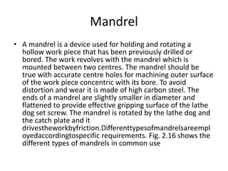
- 1. Mandrel • A mandrel is a device used for holding and rotating a hollow work piece that has been previously drilled or bored. The work revolves with the mandrel which is mounted between two centres. The mandrel should be true with accurate centre holes for machining outer surface of the work piece concentric with its bore. To avoid distortion and wear it is made of high carbon steel. The ends of a mandrel are slightly smaller in diameter and flattened to provide effective gripping surface of the lathe dog set screw. The mandrel is rotated by the lathe dog and the catch plate and it drivestheworkbyfriction.Differenttypesofmandrelsareempl oyedaccordingtospecific requirements. Fig. 2.16 shows the different types of mandrels in common use
- 3. centres • Depending upon the situation or requirement, different types of centres are used at the tailstock • A revolving centre is preferably used when desired to avoid sliding friction between the job and the centre which also rotates along with the job Ordinary centre: It is used for general works. Insert type centre: In this the steel “insert” can be replaced instead of replacing the whole centre. Half centre: It is similar to ordinary centre and used for facing bar ends without removal of the centre. Pipe centre: It is used for supporting pipes and hollow end jobs. Ball centre: It has ball shaped end to minimize the wear and strain. It is suitable for taper turning. Tipped centre: Hard alloy tip is brazed into steel shank. The hard tip has high wear resistant. Revolving centre: The ball and roller bearings are fitted into the housing to reduce friction and to take up end thrust. This is used in tail stock for supporting heavy work revolving at a high speed
- 4. Mounting of tools in centre lathe • Different types of tools, used in centre lathes, are usually mounted in the following ways: 1. HSS tools (shank type) in tool post. • HSS single point tools in rotatable (only one tool) and index able (up to four tools) tool posts 2. HSS form tools and threading tools in tool post. Carbide and ceramic inserts in tool holders. Drills and reamers, if required, in tailstock. Boring tools in tool post typically shows how a circular form or thread chasing HSS tool is fitted in the tool holder which is mounted in the tool post
- 5. Taper turning by a form tool • A broad nose tool having straight cutting edge is set on to the work at half taper angle, and is fed straight into the work to generate a tapered surface. In this method the tool angle should be properly checked before use. This method is limited to turn short length of taper only. This is due to the reason that the metal is removed by the entire cutting edge will require excessive cutting pressure, which may distort the work due to vibration and spoil the work surface.
- 6. Taper turning by swiveling the compound rest • This method is used to produce short and steep taper. In this method, work is held in a chuck and is rotated about the lathe axis. The compound rest is swiveled to the required angle and clamped in position. The angle is determined by using the formula, • tanα = 𝐷−𝑑/ 2𝑙 • Then the tool is fed by the compound rest hand wheel. This method is used for producing both internal and external taper. This method is limited to turn a short taper owing to the limited movement of the compound rest.
- 7. Taper turning by offsetting the tailstock • The principle of turning taper by this method is to shift the axis of rotation of the work piece, at an angle to the lathe axis, which is equal to half angle of the taper, and feeding the tool parallel to the lathe axis. • This is done when the body of the tailstock is made to slide on its base towards or away from the operator by a set over screw. The amount of set over being limited, this method is suitable for turning small taper on long jobs. The main disadvantage of this method is that live and dead centres are not equally stressed and the wear is not uniform. Moreover, the lathe carrier being set at an angle, the angular velocity of the work is not constant
- 9. Taper turning by using taper turning attachment • It consists of a bracket or frame which is attached to the rear end of the lathe bed and supports a guide bar pivoted at the centre. The guide bar having graduations in degrees may be swivelled on either side of the zero graduation and is set at the desired angle with the lathe axis. When this attachment is used the cross slide is delinked from the saddle by removing the binder screw. The rear end of the cross slide is then tightened with the guide block by means of a bolt. When the longitudinal feed is engaged, the tool mounted on the cross slide 18 will follow the angular path, as the guide block will slide on the guide bar set at an angle to the lathe axis.
- 10. Taper turning by combining longitudinal feed and cross feed • This is a more specialized method of turning taper. In certain lathes both longitudinal and cross feeds may be engaged simultaneously causing the tool to follow a diagonal path which is the resultant of the magnitude of the two feeds. The direction of the resultant may be changed by varying the rate of feeds by changing gears provided inside the apron
- 11. The advantages of using a taper turning attachment are • The alignment of live and dead centres being not disturbed; both straight and taper turning may be performed on a work piece in one setting without much loss of time. • Once the taper is set, any length of work piece may be turned taper within its limit. • Very steep taper on a long work piece may be turned, which cannot be done by any other method. • Accurate taper on a large number of work pieces may be turned. • Internal tapers can be turned with ease.
- 12. Thread Cutting Methods • Thread cutting is one of the most important operations performed in a centre lathe. It is possible to cut both external and internal threads with the help of threading tools. • There are a large number of thread forms that can be machined in a centre lathe such as Whitworth, ACME, ISO metric, etc. • The principle of thread cutting is to produce a helical groove on a cylindrical or conical surface by feeding the tool longitudinally when the job is revolved between centres or by a chuck (for external threads) and by a chuck (for internal threads). The longitudinal feed should be equal to the pitch of the thread to be cut per revolution of the workpiece. • The lead screw of the lathe has a definite pitch. The saddle receives its traversing motion through the lead screw. Therefore a definite ratio between the longitudinal feed and rotation of the headstock spindle should be found out so that the relative speeds of rotation of the work and the lead screw will result in the cutting of a thread of the desired pitch. This is effect by change gears arranged between the spindle and the lead screw or by the change gear mechanism or feed gear box used in a modern lathe. Thread cutting on a centre lathe is a slow process, but it is the only process of producing square threads, as other methods develop interference on the helix
- 13. Calculation for change gear ratio Metric thread on Metric lead screw
- 16. Thread cutting procedure • 1. The work piece should be rotated in anticlockwise direction when viewed from the tail stock end. • 2. The excess material is removed from the workpiece to make its diameter equal to the major diameter of the screw thread to be generated. • 3. Change gears of correct size are fitted to the end of the bed between the spindle and the lead screw. • 4. The thread cutting tool is selected such that the shape or form of the cutting edge is of the same form as the thread to be generated. In a metric thread, the included angle of the cutting edge should be ground exactly 600 . • 5. A thread tool gauge or a centre gauge is used against the turned surface of the workpiece to check the form of the cutting edge so that each face may be equally inclined to the centre line of the workpiece
- 17. • 6. Then the tool is mounted in the tool post such that the top of the tool nose is horizontal and is in line with the axis of rotation of the workpiece. • 7. The speed of the spindle is reduced by ½ to ¼ of the speed required for turning according to the type of material being machined. • 8. The tool is fed inward until it first scratches the surface of the workpiece. The graduated dial on the cross slide is noted or set to zero. Then the split nut or half nut is engaged and the tool moves along helical path over the desired length. • 9. At the end of tool travel, it is quickly withdrawn by means of cross slide. The split nut is disengaged and the carriage is returned to the starting position, for the next cut. These successive cuts are continued until the thread reaches its desired depth (checked on the dial of cross slide). • 10. For cutting left hand threads the carriage is moved from left to right (i.e. towards tail stock) and for cutting right hand threads it is moved from right to left (i.e. towards headstock).
- 18. Depth of cut in thread cutting • The depth of first cut is usually 0.2 to 0.4 mm. This is gradually decreased for the successive cuts until for the final finishing cut; it is usually 0.025 to 0.075 mm. The depth of cut is applied by advancing the tool either radially (called as plunge cutting) or at an angle equal to half angle of the thread (called as compound cutting) (300 in case of metric threads) by swiveling the compound rest
- 19. • Plunge cutting: In this the absence of side and back rake will not produce proper cutting except on brass and cast iron. Cutting takes place along a longer length of the tool. This gives rise to difficulties in machining in terms of higher cutting forces and consequently chattering. This result in poor surface finish and lower tool life, thus this method is not generally preferred. This method is used for taking very light finishing cuts and for cutting square, acme and worm threads. • Compound cutting: Compound cutting is superior to the plunge cutting as it: Permits the tool to have a top rake. Permits cutting to take place on one edge of the tool only. 23 Allows the chips to slide easily across the face of the tool without crowding. Reduces cutting strain that acts on the tool. Reduces the tendency to cause the tool to ‘dig-in’. So compound cutting is more preferred compared with plunge cutting
- 20. • Picking up the thread Several cuts are necessary before the full depth of thread is reached. It is essential that the tool tip should always follow the same thread profile generated in the first cut; otherwise the workpiece will be spoiled. This is termed as picking up the thread. The different methods of picking up the thread are: • Reversing the machine: After the end of one cut the machine is reversed while keeping the half nut permanently engaged and retaining the engagement between the tool and the workpiece. The spindle reversal would bring the cutting tool to the starting point of the thread following the same path in reverse. After giving a further depth of cut the spindle is again reversed and the thread cutting is continued in the normal way. This is easy to work and is somewhat more time consuming due to the idle time involved in stopping and reversing of the spindle at the end of each stroke. Marking the lathe parts: The procedure is to mark the lead screw and its bracket, the large gear and the head stock casting, and the starting position of the carriage on the lathe bed. The aim is to bring each of the markings on the lead screw and gear opposite the markings on the stationary portions of the lathe, and have the carriage at the starting position before attempting to engage the split nut. • Using a chasing dial:. This is also called as thread indicator. This is a special attachment used in modern lathes for accurate “picking up” of the thread. This dial indicates when to close the split or half nuts. This is mounted on the right end of the apron. It consists of a vertical shaft with a worm gear engaged with the lead screw. The top of the vertical shaft has a revolving dial marked with lines and numbers to indicate equal divisions of the circumference. The dial turns with the lead screw so long the half nut is not engaged. If the half nut is closed and the carriage moves along, the dial stands still.
- 21. As the dial turns, the graduations pass a fixed reference line. The half-nut is closed for all even threads when any line on the dial coincides with the reference line. For all odd threads, the half-nut is closed at any numbered line on the dial coincides with the reference line. The corresponding number is determined from the charts. If the pitch of the thread to be cut is an exact multiple of the pitch of the lead screw, the thread is called even thread; otherwise the thread is called odd thread.
- 22. • Thread chaser: A chaser is a multipoint threading tool having the same form and pitch of the thread to be chased. An external thread chaser is shown in Fig. 2.42 (a). A chaser is used to finish a partly cut thread to the size and shape required Thread chasing is done at about ½ of the speed of turning
- 23. • (a)Solid die: It is used for making threads of usually small pitch and diameter in one pass. • (b) Spring die: The die ring is provided with a slit, the width of the slit is adjustable by a screw to enable elastically slight reduction in the bore and thus cut the thread in number of passes with lesser force on hands. • (c) Split die: The die is made in two pieces, one fixed and one movable (adjustable) within the cavity of the handle or wrench to enable cut relatively larger threads or fine threads on harder blanks easily in number of passes, the die pieces can be replaced by another pair for cutting different threads within small range of variation in size and pitch. • (d) Pipe die: Pipe threads of large diameter but smaller pitch are cut by manually rotating the large wrench (stock) in which the die is fitted through a guide bush. However the quality of the threads will depend upon the perfection of the dies and skill of the operator External thread cutting by dies
- 24. External thread cutting by milling cutters • This process gives quite fast production by using suitable thread milling cutters in centre lathes. The milling attachment is mounted on the saddle of the lathe. Thread milling is of two types: • Long thread milling: Long and large diameter screws like machine lead screws are reasonably accurately made by using a large disc type form milling cutter). • Short thread milling: Threads of shorter length and fine pitch are machined at high production rate by using a HSS milling cutter having a number of annular threads with axial grooves cut on it for generating cutting edges. Each job requires only around 1.25 revolution of the blank and very short axial (1.25 pitch) and radial (1.5 pitch) travel of the rotating tool
- 25. Constructional features of speed gear box and feed gear box There are two types of headstock driving mechanisms as follows: • 1. Back geared headstock. • 2. All geared headstock. • Back geared headstock Back gear arrangement is used for reducing the spindle speed, which is necessary for thread cutting and knurling.
- 26. • There is one stepped cone pulley in the lathe spindle. This pulley can freely rotate on the spindle. A pinion gear P1 is connected to small end of the cone pulley. P1 will rotate when cone pulley rotates. Bull gear G1 is keyed to lathe spindle such that the spindle will rotate when Gear G1 rotates. Speed changes can be obtained by changing the flat belt on the steps. A bull gear G1 may be locked or unlocked with this cone pulley by a lock pin. • There are two back gears B1 and B2 on a back shaft. It is operated by means of hand lever L; back gears B1 and B2 can be engaged or disengaged with G1 and P1. For getting direct speed, back gear is not engaged. The step cone pulley is locked with the main spindle by using the lock pin. The flat belt is changed for different steps. Thus three or four ranges of speed can be obtained directly • For getting slow or indirect speeds, back gear is engaged by lever L and lock pin is disengaged. Now, power will flow from P1 to B1. B1 to B2 (same shaft), B2 to G1 to spindle. As gear B1 is larger than P1, the speed will further be reduced at B1. B1 and B2 will have the same speeds. The speed will further be reduced at G1 because gear G1 is larger than B2. So, the speed of spindle is reduced by engaging the back gear.
- 27. All geared headstock All geared headstock is commonly used in modern lathes because of the following advantages: • It gives wider range of spindle speeds. • It is more efficient and compact than cone pulley mechanism. • Power available at the tool is almost constant for all spindle speeds. Belt shifting is eliminated. • The vibration of the spindle is reduced. More power can be transmitted
- 28. Feed mechanisms • The feed mechanism is used to transmit power from the spindle to the carriage. Therefore, it converts rotary motion of the spindle into linear motion of the carriage. The feed can be given either by hand or automatically. For automatic feeding, the following feed mechanisms are used: Tumbler gear reversing mechanism. Quick-change gearbox. Tumbler gear quick-change gearbox. Apron mechanism. Bevel gear feed reversing mechanism. 1. Tumbler gear reversing mechanism is used to change the direction of lead screw and feed rod. By engaging tumbler gear, the carriage can be moved along the lathe axis in either direction during thread 29 cutting or automatic machining.
- 29. Quick-change gear box • Quick-change gearbox is used to get various power feeds in the lathe
- 30. Tumbler gear quick-change gear box • The different speed of the driving shaft is obtained by a tumbler gear and cone gear arrangement
- 31. Apron mechanism • Lead screw and feed rod is getting power from spindle gear through tumbler gears. Power is transmitted from feed rod to the worm wheel through gears A, B, C, D and worm. A splined shaft is attached with worm wheel. The splined shaft is always engaged with the gears F and G which are keyed to the feed check shaft. A knob ‘E’ is fitted with feed check shaft. Feed check knob ‘E’ can be placed in three positions such as neutral, push-in and pull-out
- 32. Bevel gear feed reversing mechanism • The tumbler gear mechanism being a non-rigid construction cannot be used in a modern heavy duty lathe. The clutch operated bevel gear feed reversing mechanism incorporated below the head 32 stock or in apron provides sufficient rigidity in construction
- 33. CAPSTAN AND TURRET LATHES • Capstan and turret lathes are production lathes used to manufacture any number of identical pieces in the minimum time. These lathes are development of centre lathes. The capstan lathe was first developed in the year 1860 by Pratt and Whitney of USA In contrast to centre lathes, capstan and turret lathes: o Are relatively costlier. o Are requires less skilled operator. o Possess an axially movable indexable turret (mostly hexagonal) in place of tailstock. o Holds large number of cutting tools; up to four in indexable tool post on the front slide, one in the rear slide and up to six in the turret (if hexagonal) as indicated in the schematic diagrams. 33 o Are more productive for quick engagement and overlapped functioning of the tools in addition to faster mounting and feeding of the job and rapid speed change. o Enable repetitive production of same job requiring less involvement, effort and attention of the operator for pre-setting of work-speed and feed rate and length of travel of the cutting tools. o Are suitable and economically viable for batch production or small lot production. o Capable of taking multiple cuts and combined cuts at the same time.
- 35. • Capstan and turret lathes are very similar in construction, working, application and specification • Bed: The bed is a long box like casting provided with accurate guide ways upon which the carriage and turret saddle are mounted. The bed is designed to ensure strength, rigidity and permanency of alignment under heavy duty services. • Headstock: The head stock is a large casting located at the left hand end of the bed. The headstock of capstan and turret lathes may be of the following types: Step cone pulley driven headstock. Direct electric motor driven headstock. All geared headstock. Pre-optive or pre-selective headstock.
- 36. • Bar feeding mechanisms: The capstan and turret lathes while working on bar work require some mechanism for bar feeding. The long bars which protrude out of the headstock spindle require to be fed through the spindle up to the bar stop after the first piece is completed and the collet chuck is opened. In simple cases, the bar may be pushed by hand. But this process unnecessarily increases the total production time by stopping, setting, and starting the machine. Therefore, various types of bar feeding mechanisms have been designed which push the bar forward immediately after the collet releases the work without stopping the machine, enabling the setting time to be reduced to the minimum
- 37. • The bar is passed through the bar chuck, spindle of the machine and then through the collet chuck. The bar chuck rotates in the sliding bracket body which is mounted on a long sliding bar. The bar chucks grips the bar centrally by two set screws and rotates with the bar in the sliding bracket body. One end of the chain is connected to the pin fitted on the sliding bracket and the other end supports a weight. The chain running over two fixed pulleys mounted on the sliding bar. The weight constantly exerts end thrust on the bar chuck while it revolves on the sliding bracket and forces the bar through the spindle at the moment the collet chuck is released. Thus bar feeding may be accomplished without stopping the machine.
- 38. Capstan lathe Turret lathe Turret head is mounted on a ram which slides over the saddle Turret head is directly mounted on saddle. But it slides on the bed The turret movement is limited. The turret moves on the entire length of the bed without any restriction
- 39. AUTOMATIC LATHES • Highly automated machine tools especially of the lathe family are ordinarily classified as semi automatics and automatics. Automatics as their name implies are machine tools with a fully automatic work cycle. Semi automatics are machine tools in which the actual machining operations are performed automatically in the same manner as on automatics. In this case however, the operator loads the blank into the machine, starts the machine, checks the work size and removes the completed piece by hand
- 40. • Classification of Automats • According to the type of work materials used: Bar stock machine. Chucking machine. • According to the number of spindles: Single spindle machine. Multi spindle machine. • According to the position of spindles: Horizontal spindle type. Vertical spindle type. • According to the use: General purpose machine. Single purpose machine. • According to the feed control: Single cam shaft rotating at constant speed. Single cam shaft with two speeds. Two cam shafts.
- 41. Comparison of automats and semiautomatics
- 42. • The shaper is a machine tool having a reciprocating cutting tool of the lathe type, which takes a straight line cut. It is primarily intended to produce flat surfaces. These surfaces may be horizontal, vertical or inclined. The main significance of this machine lies in its greater flexibility on account of ease in work holding, quick adjustment and use of tools of relatively simple design. In the light of above fact it is almost an indispensable machine in tool rooms die making shops and general repair shops for the production of a few identical shapes of jobs. It can also be adopted for producing curved and irregular surfaces. On a shaper the job is usually fixed in a vice on the machine table. The tool is held in the tool post, mounted on the ram of the machine. As the ram reciprocates to and for the cutting tool cuts the material in forward stroke only except in case of draw cuts shaper, in which the tool cuts in backward stroke of the ram. The other stroke in both the cases remains idle, as there is no cutting action in this stroke and hence termed as idle strokes.
- 43. Types of Shapers • Shapers are classified in a number of ways depending upon the general features of design or the purpose for which they are intended. Shapers are classified under the following headings. 1) According to the type of mechanism used for giving reciprocating motion to the ram • (a) Crank type (b) Geared type (c) Hydraulic type 2) According to the position and travel of ram • (a) Horizontal type (b) Vertical type (c) Traveling head type 3) According to the type of design of the table: • (a) Standard shaper (b) universal shaper 4) According to the type of cutting stroke • (a) Push type (b) Draw type
- 44. • Crank Shaper This is the most common type of shaper in which a single point cutting tool is given' a reciprocating motion equal to the length of the stroke desired while the work is clamped in position on an adjustable table. In construction, the crank shaper employs a crank mechanism to change circular motion of a large gear called "bull gear" incorporated in the machine for reciprocating motion of the ram. The bull gear receives power either from an individual motor or from an overhead line shaft if it is a belt driven shaper. • Geared type The reciprocating motion of the ram in some type of shaper is affected by means of a rack and pinion. The rack teeth, which are cut directly below the ram, mesh with a spur gear. The pinion meshing with the rack is driven by a gear train. The speed and the direction in which the machine will traverse depend on the number of gears in the gear train. This type of shaper is not very widely used.
- 45. • Hydraulic Shaper In a hydraulic shaper reciprocating movement of the ram is obtained by hydraulic power. Oil under high pressure is pumped in to the operating cylinder fitted with a piston. The end of the piston rod is connected to the ram. The high- pressure oil first acts on one side of the piston and then on the other causing the piston to reciprocate and the motion is transmitted to the ram. The piston speed is changed by varying the amount of liquid delivered by the pump. One of the most important advantages of this type of shaper is that the cutting speed and force of the ram drive are constant from the very beginning to the end of the cut. It also offers great flexibility up of motion when the cutting tool is overloaded. Protecting the parts or the tools from breakage. Another advantages is that the machine does not make any noise and operates very quietly. • Horizontal Shaper In a horizontal shaper, the ram holding the tool reciprocates in a horizontal axis. Horizontal shapers are mainly used to produce flat surfaces.
- 46. • Vertical Shaper In a vertical shaper, the ram holding the tool reciprocates in a vertical axis. In some of the vertical machines provision is made to allow adjustment of the ram to an angle of about 10 degrees from the vertical position. Vertical shapers may be crank driven, rack driven, screw driver or hydraulic power driven. The work table of a vertical shaper can be given cross, longitudinal, and rotary movement. The tool used on a vertical shaper is entirely different from that used on a horizontal shaper. Vertical shapers are very convenient for machining internal surfaces, keyways, slots or grooves; large internal and external gears may also be machined by indexing arrangement of the rotary table. There are vertical shapers, which are specially designed for machining internal keyways. They are then called keys eaters. • Travelling Head Shaper In a travelling head shaper, the ram carrying the tool while it reciprocates moves crosswise to give the required feed. Heavy and un widely jobs, which are very difficult to hold on the table of standard shaper and fed past the tool are, held static on the basement of the machine while the ram reciprocates and supplies the feeding movements.
- 47. • Standard or Plain Shaper A shaper is termed as standard or plain when the table has only two movements, vertical and horizontal, to give the feed. The table may or may not be supported at the outer end. • Universal Shaper In a universal shaper in addition to the two movements provided on the table of a standard shaper, the table can be swivelled about an axis parallel to the ram ways, and the upper portion of the table can be tilted about a second horizontal axis perpendicular to the first axis. As the work mounted on the table can be adjusted in different planes, the machine is most suitable for different 3 types of work and is given the name "universal". A universal shaper is mostly used in tool room work. • Push Type Shaper This is the most general type of shaper used in common practice. The metal is removed when the ram moves away from the column, i.e., pushes the work. • Draw Type Shaper In a draw shaper, the metal is removed when the ram moves towards the column of the machine, i.e., draws the work towards the machine. The tool is set in a reversed direction to that of a standard shaper. The ram is generally supported by an overhead arm which ensures rigidity and eliminates deflection of the tool. In this shaper the cutting pressure acts towards the column which relieves the cross rail and other bearings from excessive loading and allows to take deep cuts. Vibration in these machines is practically eliminated.
- 48. Specifications of a shaper • Maximum ram stroke 700mm • Maximum tool overhang 840 mm • Distance between table surface and ram Maximum 400mm Minimum 80 mm • Dimensions of table working surface 700 mm x 450 mm • Maximum travel of table Horizontal 700 mm Vertical 320 mm • Horizontal feed per double stroke 0.25-5 mm • Principal movement motor power 7 kW • Overall dimensions 2785 x 1750 x 1780 mm
- 49. Operations performed on Shaper • A shaper is a versatile machine tool primarily designed to generate a flat surface by a single point cutting tool. But it may also be used to perform many other operations. The different operations, which a shaper can perform are as follows: • 1) Machining horizontal surface • 2) Machining vertical surface • 3) Machining angular surface • 4) Cutting slots, grooves, and key ways • 5) Machining irregular surface • 6) Machining splines or cutting gears.
- 50. • Shaper Driving Mechanism In a shaper, rotary movement of the drive is converted into reciprocating movement by the mechanism contained within the column of the machine. The ram holding the tool gets the reciprocating movement. In a standard shaper the metal is removed in the forward stroke and the return stroke is idle. The time taken by idle stroke is merely waste and should be minimised as far as possible. This can achieve by making the shaper to complete its return stroke quicker than the forward one. Thus the shaper mechanism should be so designed to perform the cutting stroke at a comparatively shower speed than the return stroke and this mechanism is known as quick return mechanism. The reciprocating movement of the ram and the quick return mechanism of the machine are usually obtained by any one of the following. • 1) Crank and slotted lever mechanism • 2) Whit-worth quick return mechanism • 3) Hydraulic shaper mechanism
- 51. • Cutting slots and keyways With suitable tools a shaper can very conveniently machine slots or grooves on a work or cut external keyways on shafts and internal keyways on pulleys or gears. For cutting slots or keyways a square nose tool similar to a parting tool is selected. Fig.9.22 illustrates cutting of external keyways and Fig. shows cutting of internal keyways in a shaper. External keyways are cut on a shaft by first drilling a hole at the blind end of the keyway. The diameter of the holes should be 0.5 to 0.8mm over size than the width of the keyways and the depth should be about 1.55mm larger than the depth of keyway. This is necessary to leave a clearance on the tool at the end of the stroke. The length and position of stroke is carefully adjusted so that the stroke will terminate exactly at the clearance hole. The speed is reduced while cutting a keyway. Internal keyways are cut by holding the tool on a special tool holder so that the tool post will not hit against the work at the end of the stroke. The clapper block is locked in the clapper box to prevent the tool from lifting during return stroke. Lubrication is necessary on the work to prevent the cutting edge of the tool from wear due to dragging.
- 52. • Crank and Slotted Lever Mechanism: It consists of slotted link called rocker arm. The rocker arm is pivoted at its bottom end which forms the fulcrum. At its upper it carries another short link which is attached to the ram block • Principle of Quick Return Mechanism: When the link is in the position OQ2, the ram will be at the extreme backward position of the stroke and when it is at OQ2, it has reached the extreme forward position. Therefore the forward cutting stroke takes place when the crank rotates through the angle Pa, K P2, and the return stroke takes place when the crank rotates through the angle P2, L Pr • Hydraulic Mechanism: In a hydraulic shaper the ram is moved forward and backward by a piston moving in a cylinder placed under the ram. The machine mainly consists of a constant discharged oil pump, a valve chamber, a cylinder and a piston
- 53. • The hydraulic mechanisms are becoming popular because of the following advantages. • 1) Ability to slip in case of over load • 2) Smoother operation • 3) Ability to withstand shock without damage to the tool or the machine • 4) Infinite number of cutting speeds can be obtained from zero to the maximum value and the control easier. • 5) Possibility of changing speed and feed during operation
- 55. slotting machine • The slotting machine falls under the category of reciprocating type of machine tool similar to a shaper or a planer. It operates almost on the same principle as that of a shaper. The major difference between a slotter and shaper is that in a slotter the ram holding the tool reciprocates in a vertical axis, whereas in a shaper the ram holding the tool reciprocates in a horizontal axis. A vertical shaper and a sllotter are almost similar to each other as regards to their construction, operation, and use. The only difference being, in the case of a vertical shaper, the ram holding the tool may also reciprocate at an angle to the horizontal table in addition to the vertical stroke. The ram can be swivelled not more than 5° to the vertical. The slotter is used for cutting grooves, key ways and slots of various shapes, for making regular and irregular surfaces both internal and external, for handling large and awkward work pieces, for cutting internal or external gears and many other operations which cannot be conveniently machine in any other machined tool described before. The slotting machine was developed by Brunei in the year 1800 much earlier than a shaper was invented Base 2) Column 3) Saddle 4) Cross- slide 5) Rotating table 6) Ram and tool head assembly 7) Ram drive mechanism 8) Feed mechanism
- 56. • Base or Bed The base is rigidly built to take up all the cutting forces and entire load of the machine. The top of the bed is accurately finished to provide guide ways on which the saddle is mounted. The guide ways are perpendicular to the column face. Column The column is the vertical member, which is cast integral with the base and houses driving mechanism of the ram and feeding mechanism. The front vertical face of the column is accurately finished for providing ways on which the ram reciprocates. • Saddle The saddle is mounted upon the guideways and may be moved toward or away from the column either by power or manual control to supply longitudinal feed to the work. The top face of the saddle is accurately finished to provide guide ways for the cross-slide. These guide ways are perpendicular to the guide ways on the base • Cross-Slide The cross-slide is mounted upon the guide ways of the saddle and may be moved parallel to the face of the column. The movement of the slide may be controlled either by hand or power to supply cross-feed. • Rotary Table The rotary table is a circular table which is mounted on the top of the cross-slide. The table may be rotated by rotating a worm which meshes with a worm gear connected to the underside of the table. The rotation of the table may be effected either by hand or power. In some machines the table is graduated in degrees that enable the table to be rotated for indexing or dividing the periphery of a job in equal number of parts. T-slots are cut on the top face of the table for holding the work by different clamping devices. The rotary table enables a circular or contoured surface to be - generated on the work piece
- 57. PLANNING MACHINES &Principles of working • A planer is a machine having reciprocating work and fixed tool. The work traverses the tool and feeds over at the end of each stroke the tool is clamped in the tool holder and the work on the table • The type of work is very similar to that done on a shaper except that a plane is adapted to much large work. The cuts are all plain surfaces, but they may be horizontal, vertical or at any angle. Both the planer and shaper employ single- point cutting tools for machining. The planer is very heavy in construction and had long table travel. It can take multi-cuts at various places in a single stroke, because it can accommodate more than one tool holding stations. It is also possible to machine large number of smaller parts by setting them properly on the table usually, two tool heads are mounted on the overhead cross rail and one each on either of the column. Like all reciprocating machine tools, the planer is quipped with a clapper box to raise the tool on the return stroke.
- 58. Although both the planer and shaper employ single-point cutting tools for machining flat surfaces, they are not similar in their field of usefulness: they differ widely in construction and in method of operation when the two machines are compared in construction, operation and use, the following difference may be seen. • 1) The planer is very heavy and robust machine in construction the shaper is smaller one. • 2) On planer the work is moved against the stationary tool, on shaper the tool is moved against the stationary work. • 3) On planner the feed is given to the tool, on shaper the feed is given to the work. • 4) In planer the work table is drive either by gears or by hydraulic means. The shaper ram can also be driven in this manner, but in most cases the quick return mechanism is used. • 5) Most planers differ from shapers in that they approach constant velocity cuts. • 6) The planer is specially adopted to large work; the shaper can do only small work. • 7) In a planer the tool is rigidly supported when the work moves on precision ways and maximum accuracy on the machined surface is assured. In a shaper, due to overhanging of the ram during the cutting stroke, and the machine being not very robust the accuracy cannot be expected up to the mark. • 8) High rate of power consumption and overall rigidity in a planer enables it to take deep cuts and apply heavy feeds to rough finish a job quickly. A planer can consume up to 150 h.p. Whereas a shaper can consume 15 to 20 h.p. • 9) A planer is not suitable for machining relatively small, and medium size work or few at a time that a shaper can do, but a planer is more economical and faster when large quantities are machined. A large number of jobs of identical shapers can be machined in one setting on a planer table. • 10) Multiple tooling with double or four tool heads in a planer makes it possible to machine more than one surface together, thus reducing cutting time. • 11) In a planning machine, work setting requires much of skill and takes along time, whereas in a shaper the work may be clamped easily and quickly. • 12) Tools used in a planer are much more robust than that used in a shaper. • 13) In modern planes wide range of cutting and return speeds are available and they may be changed independently. • 14) Planers are larger and costlier machines compared to shapers.
- 59. Classification of Planer According to the general construction the planers are of five types: • 1) Double housing planer • 2) Open-side planer • 3) Universal planer • 4) Pit type planer • 5) Edge or plate planer. Each of the above types may vary according to the method of drive as follows: • 1) Gear drive • 2) Hydraulic drive • 3) Screw drive • 4) Belt drive • 5) Variable-speed motor drive • 6) Crank drive.