Power Quality Improvement Fuzzy Logical Controlled Based on Cascaded Shunt Active Power Filter
•
0 likes•49 views

Improve its quality and reliability catches growing interest. In this paper, based on the analysis and modeling of the shunt APF with close-loop control, a feed forward compensation path of load current and also fuzzy logic control is applied to improve the dynamic performance of the APF.. The two H-bridge cascaded inverter is used for the aeronautical APF (AAPF). Justifications for topology choosing and corresponding system control method are given. Furthermore, the global framework and operation principle of the proposed AAPF are presented in detail. Simulated waveforms in different load conditions indicate the good performance of the AAPF.
![31 International Journal for Modern Trends in Science and Technology
Power Quality Improvement Fuzzy Logical Controlled Based on Cascaded Shunt Active Power Filter
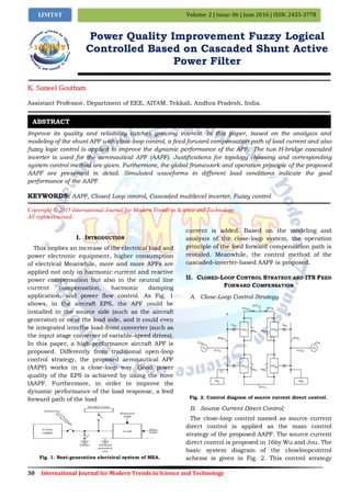
operates as follows: The dc-link voltage is sent to
the voltage regulator, and the output of the
regulator is sent to the multipliers well as a
synchronous sine wave which is detected from the
phase voltage. The output of the multiplier is sent
to the current regulator, being the source current
reference. The output of the current regulator will
be sent to the modulator to generate the pulse
width modulation waveforms. Fig. 3 gives the
equivalent control model of this compensation
strategy. As shown in Fig. 3, the source current
reference of the source current direct control
comes from the variation of the dc-link voltage.
Here, Gv(s) corresponds to the transfer function of
the voltage controller; Kf is the dc-link voltage
detection coefficient
This control strategy operates as follows: The
dc-link voltage is sent to the voltage regulator, and
the output of the regulator is sent to the multiplier
as well as a synchronous sine wave which is
detected from the phase voltage. In the close-loop
control, detection and control target is the source
current. In the aircraft EPS, the fundamental
frequency is much higher than 50-Hz power
system. Furthermore, measure errors, analog to
digital conversion time, digital delay, and
othernonideal factors will deteriorate the open-loop
compensation effect to a worse degree. As we
known, feedback control has the following merits:
It could reduce the transfer function from
disturbances to the output, and it causes the
transfer function from the reference input to the
output to be insensitive to variations in the gains in
the forward path. Therefore, compared with
open-loop control, close-loop control is more
suitable for the aeronautical application.
Fig. 3. Model for active power analysis.
III. CONTROL METHOD OF THE CASCADED INVERTER
BASED AAPF
A. Discussion and Demonstration on the Power
Stage of AAPF
A shunt APF acts as a controlled harmonic
current source, injecting current which is inverse
equivalent to the load harmonic.In the 400-Hz
aircraft EPS, frequencies of the 11th and 13th
harmonics reach as high as 4.4 and 5.2 kHz. The
cascaded multilevel inverter (CMLI) shown in Fig 3.
is one of the most important topology in the family
of multilevel inverters. It requires least number of
components when compared to diode-clamped and
flying capacitors type multilevel inverters [9]. In
addition it has several advantages that have made
it attractive in power systems and drive
applications [10].
Fig 4:Four possible solutions of AAPF. (a)
Three-leg-inverter-based APF. (b) H-bridge-based APF. (c)
Two H-bridge cascaded APF. (d) Four H-bridge cascaded APF
Nowadays, the increase in the usage of
non-linear loads especially the power electronic
equipments leads to deterioration of the quality of
voltage waveforms at the point of common
coupling (PCC) of various consumers. Active power
Filter (APF) has been used to mitigate the
harmonic pollution in electrical networks. APF
acts as an ideal current source and inject the
compensating current into the ac lines by selective
harmonic compensation in order to cancel the line
current harmonics. The deteriorating quality of
electric power is mainly because of current and
voltage harmonics due to wide spread application
of static power converters, zero and negative
sequence components originated by the use of
single phase and unbalanced loads, reactive
power, voltage sag, voltage swell, flicker, voltage
interruption etc. 1. To improve the power quality
traditional compensation methods such as passive
filters used have many disadvantages such as
fixed compensation, bulkiness, electromagnetic
interference and possible resonance etc.,
Fig. 5 Block diagram of shunt active power filter](data:image/gif;base64,R0lGODlhAQABAIAAAAAAAP///yH5BAEAAAAALAAAAAABAAEAAAIBRAA7)
Recommended
Recommended
More Related Content
What's hot
What's hot (20)
Viewers also liked
Viewers also liked (17)
Similar to Power Quality Improvement Fuzzy Logical Controlled Based on Cascaded Shunt Active Power Filter
Similar to Power Quality Improvement Fuzzy Logical Controlled Based on Cascaded Shunt Active Power Filter (20)
Recently uploaded
Recently uploaded (20)
Power Quality Improvement Fuzzy Logical Controlled Based on Cascaded Shunt Active Power Filter
- 1. 30 International Journal for Modern Trends in Science and Technology Volume: 2 | Issue: 06 | June 2016 | ISSN: 2455-3778IJMTST Power Quality Improvement Fuzzy Logical Controlled Based on Cascaded Shunt Active Power Filter K. Suneel Goutham Assistant Professor, Department of EEE, AITAM, Tekkali, Andhra Pradesh, India. Improve its quality and reliability catches growing interest. In this paper, based on the analysis and modeling of the shunt APF with close-loop control, a feed forward compensation path of load current and also fuzzy logic control is applied to improve the dynamic performance of the APF.. The two H-bridge cascaded inverter is used for the aeronautical APF (AAPF). Justifications for topology choosing and corresponding system control method are given. Furthermore, the global framework and operation principle of the proposed AAPF are presented in detail. Simulated waveforms in different load conditions indicate the good performance of the AAPF. KEYWORDS: AAPF, Closed Loop control, Cascaded multilevel inverter, Fuzzy control Copyright © 2015 International Journal for Modern Trends in Science and Technology All rights reserved. I. INTRODUCTION This implies an increase of the electrical load and power electronic equipment, higher consumption of electrical Meanwhile, more and more APFs are applied not only in harmonic current and reactive power compensation but also in the neutral line current compensation, harmonic damping application, and power flow control. As Fig. 1 shows, in the aircraft EPS, the APF could be installed in the source side (such as the aircraft generator) or near the load side, and it could even be integrated into the load-front converter (such as the input stage converter of variable-speed drives). In this paper, a high-performance aircraft APF is proposed. Differently from traditional open-loop control strategy, the proposed aeronautical APF (AAPF) works in a close-loop way. Good power quality of the EPS is achieved by using the nove lAAPF. Furthermore, in order to improve the dynamic performance of the load response, a feed forward path of the load Fig. 1. Next-generation electrical system of MEA. current is added. Based on the modeling and analysis of the close-loop system, the operation principle of the feed forward compensation path is revealed. Meanwhile, the control method of the cascaded-inverter-based AAPF is proposed. II. CLOSED-LOOP CONTROL STRATEGY AND ITS FEED FORWARD COMPENSATION A. Close-Loop Control Strategy Fig. 2. Control diagram of source current direct control. B. Source Current Direct Control: The close-loop control named as source current direct control is applied as the main control strategy of the proposed AAPF. The source current direct control is proposed in 16by Wu and Jou. The basic system diagram of the closeloopcontrol scheme is given in Fig. 2. This control strategy ABSTRACT
- 2. 31 International Journal for Modern Trends in Science and Technology Power Quality Improvement Fuzzy Logical Controlled Based on Cascaded Shunt Active Power Filter operates as follows: The dc-link voltage is sent to the voltage regulator, and the output of the regulator is sent to the multipliers well as a synchronous sine wave which is detected from the phase voltage. The output of the multiplier is sent to the current regulator, being the source current reference. The output of the current regulator will be sent to the modulator to generate the pulse width modulation waveforms. Fig. 3 gives the equivalent control model of this compensation strategy. As shown in Fig. 3, the source current reference of the source current direct control comes from the variation of the dc-link voltage. Here, Gv(s) corresponds to the transfer function of the voltage controller; Kf is the dc-link voltage detection coefficient This control strategy operates as follows: The dc-link voltage is sent to the voltage regulator, and the output of the regulator is sent to the multiplier as well as a synchronous sine wave which is detected from the phase voltage. In the close-loop control, detection and control target is the source current. In the aircraft EPS, the fundamental frequency is much higher than 50-Hz power system. Furthermore, measure errors, analog to digital conversion time, digital delay, and othernonideal factors will deteriorate the open-loop compensation effect to a worse degree. As we known, feedback control has the following merits: It could reduce the transfer function from disturbances to the output, and it causes the transfer function from the reference input to the output to be insensitive to variations in the gains in the forward path. Therefore, compared with open-loop control, close-loop control is more suitable for the aeronautical application. Fig. 3. Model for active power analysis. III. CONTROL METHOD OF THE CASCADED INVERTER BASED AAPF A. Discussion and Demonstration on the Power Stage of AAPF A shunt APF acts as a controlled harmonic current source, injecting current which is inverse equivalent to the load harmonic.In the 400-Hz aircraft EPS, frequencies of the 11th and 13th harmonics reach as high as 4.4 and 5.2 kHz. The cascaded multilevel inverter (CMLI) shown in Fig 3. is one of the most important topology in the family of multilevel inverters. It requires least number of components when compared to diode-clamped and flying capacitors type multilevel inverters [9]. In addition it has several advantages that have made it attractive in power systems and drive applications [10]. Fig 4:Four possible solutions of AAPF. (a) Three-leg-inverter-based APF. (b) H-bridge-based APF. (c) Two H-bridge cascaded APF. (d) Four H-bridge cascaded APF Nowadays, the increase in the usage of non-linear loads especially the power electronic equipments leads to deterioration of the quality of voltage waveforms at the point of common coupling (PCC) of various consumers. Active power Filter (APF) has been used to mitigate the harmonic pollution in electrical networks. APF acts as an ideal current source and inject the compensating current into the ac lines by selective harmonic compensation in order to cancel the line current harmonics. The deteriorating quality of electric power is mainly because of current and voltage harmonics due to wide spread application of static power converters, zero and negative sequence components originated by the use of single phase and unbalanced loads, reactive power, voltage sag, voltage swell, flicker, voltage interruption etc. 1. To improve the power quality traditional compensation methods such as passive filters used have many disadvantages such as fixed compensation, bulkiness, electromagnetic interference and possible resonance etc., Fig. 5 Block diagram of shunt active power filter
- 3. 32 International Journal for Modern Trends in Science and Technology Volume: 2 | Issue: 06 | June 2016 | ISSN: 2455-3778IJMTST At low voltage levels, conventional two level inverters are used. At medium voltage levels, the conventional two level inverters either require interface transformers between the inverter terminals and the supply terminals or need active devices to be connected in series to achieve the required voltage levels. The multilevel inverters 4 are able to achieve the required voltage levels using devices of low voltage rating. Hence in this proposed work, the APF is realized using the cascaded H-bridge multi-level inverter. Besides, steps are taken to operate the inverter in the over modulation region. B. Active Power Filter: The increased severity of harmonic pollution in power networks has attracted the attention of power electronics and power system engineers to develop dynamic and adjustable solutions to the power quality problems. Such equipments, generally known as active filters 7, are also called active power line conditioners. To effectively compensate the line current harmonics, the active filter controller should be designed to meet the following three goals: C. Discussion and Demonstration on the Power Stage of AAPF Compared with the last two solutions, switching power loss plays important roles for the first two solutions. Un negligible switching power losses make the first two solutions less competitive when the switching frequency Increases Negligible switching power losses in the last two solutions make the total power losses smaller in a wide range of switching frequency. Meanwhile, power losses of the last two solutions are nearly in the same level. IV. MATLAB/SIMULATION RESULTS A. Cascaded Shunt Active Power Filter: Fig 6Cascaded Shunt Active Power Filter Fig 7: Simulation waveforms of AAPF under variable-frequency EPS. Fig 8: Simulation waveforms of AAPF under variable-frequency voltage and current B. Fuzzy Logic Controller for Cascaded Shunt Active Power Filter: Fig9.Fuzzy Logic Controller for Cascaded Shunt Active Power Filter Fig10.mamdani controlled using Cascaded Shunt Active Power Filter
- 4. 33 International Journal for Modern Trends in Science and Technology Power Quality Improvement Fuzzy Logical Controlled Based on Cascaded Shunt Active Power Filter Fig11.mamdani controlled by using Fuzzy Logic Controller Cascaded Shunt Active Power Filte Fig12.Simulation waveforms of AAPF under variable-frequency EPS. Fig 13.Simulation waveforms of AAPF under variable-frequency voltage and current V. CONCLUSION In this paper, a load current feed forward compensation method for the source current direct control and fuzzy controller based AAPF has been proposed. The corresponding system control strategy of the cascaded-inverter based active filter system is shown. The cascaded H-bridge inverter has been used for active power filter. Then the role of APF in compensating the line current harmonics has been demonstrated by considering certain non-linear loads. Simulation results show that the dominant harmonics in the line current and total harmonic distortion have been reduced significantly. Hence there is an improvement in the power quality. REFERENCES [1] J. A. Rosero, J. A. Ortega, E. Aldabas, and L. Romeral, “Moving towardsa more electric aircraft,” IEEE Aerosp. Electron. Syst. Mag., vol. 22, no. 3,pp. 3–9, Mar. 2007. [2] A. Hamadi, S. Rahmani, and K. Al-Haddad, “A hybrid passive filterconfiguration for VAR control and harmonic compensation,” IEEE Trans.Ind. Electron., vol. 57, no. 7, pp. 2419–2434, Jul. 2010. [3] A. Varschavsky, J. Dixon, M. Rotella, and L.Moran, “Cascaded nine-levelinverter for hybrid-series active power filter, using industrial controller,”IEEE Trans. Ind. Electron., vol. 57, no. 8, pp. 2761–2767, Aug. 2010 [4] B. Singh and J. Solanki, “An implementation of an adaptive control algorithmfor a three-phase shunt active filter,” IEEE Trans. Ind. Electron.,vol. 56, no. 8, pp. 2811–2820, Aug. 2009. [5] A. Bhattacharya and C. Chakraborty, “A shunt active power filter withenhanced performance using ANN-based predictive and adaptive controllers,”IEEE Trans. Ind. Electron., vol. 58, no. 2, pp. 421–428,Feb. 2011. [6] .A. Luo, X. Xu, L. Fang, H. Fang, J. Wu, and C. Wu, “Feedback–feedforward PI-type iterative learning control strategy for hybrid activepower filter with injection circuit,” IEEE Trans. Ind. Electron., vol. 57,no. 11, pp. 3767–3779, Nov. 2010. [7] S. Rahmani, N. Mendalek, and K. Al-Haddad, “Experimental design ofa nonlinear control technique for three-phase shunt active power filter,”IEEE Trans. Ind. Electron., vol. 57, no. 10, pp. 3364–3375, Oct. 2010. [8] D. Ganthony and C. M. Bingham, “Integrated series active filter foraerospace flight control surface actuation,” in Proc. EPE, 2007, pp. 1–9. [9] E. Lavopa, E. Summer, P. Zanchetta, C. Ladisa, and F. Cupertimo, “Realtimeestimation of fundamental frequency and harmonics for active powerfilters applications in aircraft electrical systems,” in Proc. EPE, 2007,pp. 4220–4229. [10] E. Lavopa, M. Summer, P. Zanchetta, C. Ladisa, and F. Cupertimo,“Real-time estimation of fundamental frequency and harmonics for activepower filters applications in aircraft electrical systems,” IEEE Trans. Ind.Electron., vol. 56, no. 8, pp. 2875–2884, Aug. 2009. [11]M. Odavic, P. Zanchetta, and M. Summer, “A low switching frequencyhigh bandwidth current control for active shunt power filter in aircraftspower networks,” in Proc. IEEE IECON, 2007, pp. 1863–1868.