1) The document describes a hardware-in-the-loop (HIL) simulation system used to test a marine diesel engine monitoring system.
2) The HIL system connects a simulation ECU to the monitoring system instead of an actual engine. The simulation ECU generates sensor signals to simulate engine conditions.
3) Testing showed the monitoring system functions properly during fault diagnosis and monitoring when used with the HIL simulation system. The HIL approach allows effective development and testing of marine engine monitoring systems.
Research of Hardware-In-The-Loop System of Monitor System of Marine Diesel Engines
1. International Journal of Research in Engineering and Science (IJRES)
ISSN (Online): 2320-9364, ISSN (Print): 2320-9356
www.ijres.org Volume 5 Issue 5 ǁ May. 2017 ǁ PP. 51-54
www.ijres.org 51 | Page
Research of Hardware-In-The-Loop System of Monitor System of
Marine Diesel Engines
Wenjing Li1
, Hao Chen2
, Ningning Liu3
(College Of Automotive Engineering,Shanghai University Of Engineering Science,Shanghai 201620,China)
ABSTRACT: In order to improve the remote fault diagnosis and monitoring items of marine diesel engine,
improve the development efficiency of monitor system of marine diesel engines. Hardware-in-the-loop
simulation test has already been validated in developing monitor system of marine diesel engines. Build
database of CAN application layer protocol .The information packet sends simulation process of diesel fuel
injection. Infineon XC2765 is used to develop the simulation ECU. Sensor signals generated by the simulation
ECU simulate the work of marine diesel engine in order to test the monitor system of marine diesel engines.
Keywords: the monitoring system of diesel engine, Hardware in the loop simulation technology, CAN-bus,
simulation ECU
I. TNTRODUCTION
Hardware in the loop simulation(HILS) is a complex simulation system which mix physical model,
mathematical model and entity. It's a real - time and dynamic simulation technology. Specifically, using the
model on the computer instead of the controlled object of the closed - loop test system. Connect the physical
with the simulation system in order to test the function of the object. HILS can make full use of the power of the
computer, reducing the cost of research and improve the efficiency of development greatly. There is no need to
build any model. Simulation of a single module can save a lot of time.
II. WORKING PRINCIPLE OF SYSTEM
The monitoring system of diesel engine of ship is mainly composed of engine ECU, monitoring and
security system, remote monitoring system and abutment control system. It's used to control and monitor the
marine diesel engines. Reasonable and reliable test environment is very important for the development of the
monitoring system of diesel engine of ship. Each system of the monitoring system of diesel engine of ship
works independent. CAN is used to communicate which can ensure the accuracy ,reliability and efficiency of
transmission of data. The advantage of CAN bus is high speed, high reliability and convenient connection.
That makes high flexibility and reliability. Through the fault diagnosis system of CAN bus, fault diagnosis and
acquisition of fault code information is quick and reliable. COMPUTER and emulation ECU instead of the
actual working diesel engine connect with the monitoring ECU in the simulation system that save the cost of
experiment. Through HILS the monitoring system of diesel engine can be tested.
III. OVERALL SYSTEM DESIGN
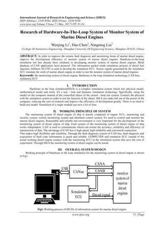
Working principle of Hardware in the loop simulation for the monitoring system of diesel engine is shown
in Fig1.
CANoe
Simulation
ECU
monitor
system of
marine
diesel
engines
USB
CANA
CANB
Diesel signal
Fig1. Working process of HILSS of information system for marine diesel engine
2. Research Of Hardware-In-The-Loop System Of Monitor System Of Marine Diesel Engines
www.ijres.org 52 | Page
3.1 Design of CAN bus network control system
In Hardware-in-the-loop simulation system, the internal communication between the subsystems based
on the CAN bus.
Reasonable CAN bus can improve the reliability and stability of Hardware-in-the-loop simulation
system for monitoring system of diesel engine. The main structure is shown in Fig2.
Remote
monitoring ECU
Abutment
Monitoring ECU
Lateral
monitoring ECUECU by CANoe
CAN
BUS
A&B
Fig2. Network topology of the CAN bus
The system consists of remote monitoring ECU, lateral monitoring ECU and abutment monitoring
ECU.PC simulates the work process of diesel Engine ECU through CANoe and output the state parameters of
marine electronic diesel engine which are sent to the monitoring ECU .CAN is used to exchange state
parameters between different nodes.
3.2 Hardware design of Hardware in the loop simulation(HILS)
The function of simulation ECU is to simulate the condition parameters of engine which provides a
virtual test environment for the marine diesel engine monitoring system. Working principle is shown in Fig3.
CANoe
PWM
SPI
Infineon
XC2765
Speed signal
Temperature signal
Pressure signal
Fig3. Working principle of simulation ECU
Computer sends a digital signal to the simulation ECU. CANoe is used to connect them so that data can
communicate with each other. Simulation ECU sent signal of sensor through D/A to the monitoring system of
diesel engine in order to test the function of the system developed.
3.3 Software design of Hardware in the loop simulation(HILS)
The simulation ECU is developed based on Infineon XC2000 family XC2765. During the development
of simulation ECU DAVE(Digital Application Virtual Engineer) and TASKING VX-toolset is used. The control
program of simulation ECU includes initialization module, analog signal generation module, pulse signal
generation module and communication module. Each module is designed, programmed and debugged separately
and connected finally. Control process is shown in Fig4.
3. Research Of Hardware-In-The-Loop System Of Monitor System Of Marine Diesel Engines
www.ijres.org 53 | Page
initialize
CAN accepts
interrupt
ExtractCAN
messages
nothing
changed
endOutputthe
signalNo
Yes
Yes
No
Fig4. Flow of ECU overall control simulation
Firstly we initialize the microcontroller driver. If there is an interrupt of CAN the simulation ECU
extract message of CAN and compare with the data received last time to decide whether to update the data of
sensor. If the data is different of the last time it'll output the new data.
IV. VERIFICATION AND CONCLUSION
We choose the simulation ECU as test object. The test window is developed by DAVE(Digital Application
Virtual Engineer). After the Hardware in the loop simulation(HILS) system is established, we can test the
function intuitionally . The data is shown in Fig5.
Fig5. Simulation test results of CANoe
The Trace window displays the ID, transmission direction, length, and content of the communication
data on the bus. The message is sent cyclically. The curve changes from minimum to maximum constantly so
that we can catch the test results visually. Through the window of CAN Statistics, we find that each message is
sent in accordance with the regular scheduling time and there is no delay or error frame. The CAN message data
simulated by CANoe is shown in Fig6.
Fig6. CANoe simulation of ECU sending CAN message data
4. Research Of Hardware-In-The-Loop System Of Monitor System Of Marine Diesel Engines
www.ijres.org 54 | Page
Through the analysis above we can see the CAN bus running in good condition. After testing, each
function of the monitor system of marine diesel engines such as fault diagnosis and monitoring is good. In
addition, the Hardware in the loop simulation technology can be used in development of system.
REFERENCE
[1]. MortezaMontazeri-Gh.Real-time multi-rate HIL simulation platform for evaluation of a jetengine fuel
controller [J].Simulation Modelling Practice and Theory 19 (2011): 996–1006.
[2]. A.Palladino.A portable hardware-in-the-loop (HIL) device for automotive diagnosticcontrol systems[J].
ISA Transactions 51 (2012):229–236.
[3]. P.J. Gawthrop.Emulator-based control for actuator-based hardware-in-the-loop testing[J].Control
Engineering Practice 16 (2008):897–908.