SlideShare a Scribd company logo
1 of 5
Download to read offline
International Journal of Research in Advent Technology, Vol.2, No.9, September 2014 
E-ISSN: 2321-9637 
6 
Design Optimisation of an Industrial Structure from 
Steel Frame to Pre-Engineered Building 
Kavya.Rao.M.N1, K.N.Vishwanath2 
M.Tech student,Department of Civil Engineering, DSCE , Bangalore, Karnataka, India1 
Associate Professor ,Department of Civil Engineering, Bangalore , Karnataka, India2 
E-mail: raokavya11@gmail.com1, vishuknv@yahoo.com2 
Abstract-Over the years, the technological improvements have contributed in enhancing the quality of our daily 
life to a large extent. Pre-engineered buildings are one such example in this revolution. Though it is known to 
have its origin in 1960’s it has been in practice widely only during the recent years. The Pre-Engineered 
Building (PEB) is a new concept of single storey industrial building construction. It includes the technique of 
providing the best possible section according to the optimum requirement. This papergives a comparative study 
of Pre-Engineered Building (PEB) concept and Conventional Steel Building (CSB) concept. The study is 
achieved by designing an industrial building using both the concepts and analyzing them using the structural 
analysis and design software Staad pro. To achieve this, PEB andCSB are designed for dynamic forces, which 
include wind forces. The results obtained from the study shows that Pre- engineered buildings are advantageous 
over conventional steel buildings. 
Index terms- Pre-Engineered Building, Conventional Steel Building, Staad pro. 
1. INTRODUCTION 
Steel is a material having high strength per unit 
mass. Hence it is used in the construction of 
column-free space structures. Steel structures are 
built in a very short time as time is an important 
consideration, which are widely used in the 
construction of industrial buildings.An industrial 
building is usually a single storey steel structure 
with or without mezzanine floors. Brick masonry, 
concrete walls or GI sheet coverings may be the 
enclosures of these structures. Generally the walls 
are non-bearing but sufficiently strong enough to 
withstand the lateral forces caused by wind or 
earthquake. These buildings can be categorized as 
Pre-Engineered Buildings (PEB) and Conventional 
Steel Buildings (CSB) according to the design 
concepts. PEB’s are nothing but steel buildings in 
which excess steel is avoided by tapering the 
sections as per the bendingmoment’s 
requirement.If we go for regular steel structures, 
time required and cost will be 
morewhichtogethermakes it uneconomical. Thus 
these buildings are fabricated fully in the factory 
after designing and then brought to the site. All the 
components are erected at the site with nut and 
bolts system which in total reduces the time needed 
for the completion of the structure. 
This paper starts with the introduction to PEB and 
CSB systems. Load and load combinations 
considered in the analysis of the structure can be 
seen in the further portions. Final portion explains 
the results obtained from the software analysis of 
the structure and the inferences made from the 
same along with the inferences from the literature 
studies. The paper aims at stating the advantages of 
PEB over CSB. 
2. METHODOLOGY 
The present paper includes the design of an 
Industrial buildingconsidered to be located at 
Bangalore. The structure is proposed as a Pre- 
Engineered Building with 66 meter span and 34.2 
meter width with an eave height of 7.5 meter. The 
design is carried out by considering wind load as 
the critical load for the structure. CSB frame is also 
designed for the same span. Both the designs are 
then compared to find out the economic output. 
The designs are carried out in accordance with the 
Indian Standards and by the help of the structural 
analysis and design software Staad.pro. 
2.1. Pre-Engineered Buildings 
Pre-Engineered Buildingsare the steel buildings 
which are predesigned and prefabricated. The basis 
of the PEB concept lies in providing the section at 
a location according to the requirement at that spot. 
These sections can be varying throughout the 
length according to the bending moment diagram. 
To achieve this criteria, tapered I sections made 
with built-up thin plates are adopted. The use of 
optimum least section leads to effective savings in 
steel and cost reduction. 
2.2. Conventional Steel Buildings 
Standard hot rolled I or C sections are used which 
may be in many segments much heavier than what 
is actually required as per design in CSB. These 
sections have standard dimensions which cannot be 
altered as per the requirement. The dimensions and 
loading details are same as in PEB. The CSB is
International Journal of Research in Advent Technology, Vol.2, No.9, September 2014 
E-ISSN: 2321-9637 
7 
then analyzed and designed using the software in 
the same manner as in PEB. 
2.3.Design software Staad pro 
Staad pro is a powerful tool for computerized 
structural engineering for 3D model generation, 
analysis and multi-material design. It has been the 
choice of design professionals around the world for 
the static or dynamic analysis of the steel 
structure.It gives theBending Moment, Axial 
Forces, Shear Forces, Torsion and Beam Stresses 
of bothPEB and CSB so that the design canbe done 
using tapered and standard sections and checked 
for safety. 
3. ANALYSIS AND DESIGN 
The analysis and design of the proposed PEB and 
CSB are done using Staad pro 2007 and IS codes. 
Structural components of the study considered for 
the analysis and design are: 
(1) Main frame 
(2) Gable end frame 
(3) Secondary structural components: Roof 
purlins, Wall girts and Bracing system 
(4) Connections 
· Main frame connections 
· End frame connections 
3.1. Building details: 
The plan of the building is shown in figure 1. 
Building type : Clear span PEB and 
CSB 
Length of the building : 66 m 
Width of the building : 34.2 m 
No. of bays along length : 11 no.s of each 6 m 
No. of bays along width : 4 Nos. of each length 
5.53 m and 2 Nos. of each length 6.04 m 
Slope of roof : 1 in 6 
Eave height of the building: 7.5 m 
Roof purlins : Span 6 m. Continuous 
and spaced at 1.4 m c/c 
Wall girts : Span 6 m. Continuous 
and spaced at 1.4 m c/c 
Fig.1. Building plan 
3.2. Loads and Load combinations: 
A building must be designed to support its own 
dead load, a specified live load and a specified 
wind load as a minimum requirement. Other loads 
such as seismic loads, crane loads, collateral loads, 
mezzanine loads or thermal loads are considered 
only when specified by the customer. For the PEB 
structure wind load is critical and hence the load 
calculation for the structure can be carried out in 
accordance with IS:875(Part 3)-1987. Therefore the 
load combinations of dead load, live load and wind 
load are incorporated in the design. 
3.2.1. Dead load: 
Sheet load = 0.11 kN/ m2
International Journal of Research in Advent Technology, Vol.2, No.9, September 2014 
E-ISSN: 2321-9637 
8 
Total Dead load per meter = 0.11*1.4 
= 0.154 kN/m2 
Truss angle = 9.35 deg. 
Horizontal load = 0.024kN/m2 
Vertical load = 0.152 kN/m2 
3.2.2. Live load: 
On roof sheet = 0.75 kN/m2 
Total live load per meter = 0.75*1.4 
= 1.050 kN/m2 
Truss angle = 9.35 deg. 
Horizontal load = 0.167kN/m2 
Vertical load = 1.037kN/m2 
3.2.3. Wind load: 
Wind load is calculated as per IS:875 (Part 3)- 
1987. The wind load over the roof can be provided 
as uniformly distributed load acting outward over 
the rafter. For side walls, the wind load is applied 
as uniformly distributed loads acting inward or 
outward to the walls according to the wind case. 
Design wind speed as per Clause 5.3, IS:875 (Part 
3) – 1987 is given by, 
Vz = Vb * k1 * k2 * k3For Bangalore, Vb = 
33 m/s, from appendix A as per IS: 875 (Part 3) – 
1987 
k1 = 1.00, from table 1 as per IS: 875 (Part 3) – 
1987 
k2 = 0.98, from table 2 for terrain category 2- Class 
B buildings 
k3 = 1, for upwind slope (θ) less than 30 
Therefore Design wind speed (Vz) = Vb * k1 * k2 * 
k3 
= 33 * 1.0 * 0.98 * 1.0 
= 32.34 m/s 
Design wind pressure is given by, pz = 0.6 Vz 
2 
= 0.6 * 32.342 
= 627.52 N/m2 
= 0.628 KN/m2 
3.2.4. Design wind loads: 
Depending on the internal and external pressure co-efficients, 
four different wind load cases are 
considered in this study. 
For Internal pressure co-efficient, two design 
conditions shall be examined in the case of the 
buildings where the claddings permit the flow of 
air with openings not more than about 5 percent of 
the wall area but where there are no large openings. 
Therefore internal pressure co-efficient of +0.2 and 
-0.2 are taken. 
External pressure co-efficients are taken from table 
5 of IS: 875 (part 3) – 1987 for roof and table 4 of 
IS: 875 (part 3) – 1987 for sides and gable end. 
Final wind loads (kN/m) are as below in table 1: 
Wind load case 1: 
Wind angle=0, windward side+exhaust 
Wind angle=0, leeward side+exhaust 
Wind load case 2: 
Wind angle=0, windward side+suction 
Wind angle=0, leeward side+suction 
Wind load case 3: 
Wind angle=90, windward side+exhaust 
Wind angle=90, leeward side+exhaust 
Wind load case 4: 
Wind angle=90, windward side+suction 
Wind angle=90, leeward side+suction 
Table 1. Final wind loads (kN/m) 
Applied area of the building WL1 WL2 WL3 WL4 
Roof Vertical windward 1.214 0.867 0.867 0.52 
Horizontal windward -0.195 -0.139 -0.139 -0.084 
Vertical leeward 0.52 0.173 0.694 0.347 
Horizontal leeward 0.084 0.028 0.112 0.056 
Side Windward 0.439 0.791 -0.615 -0.264
International Journal of Research in Advent Technology, Vol.2, No.9, September 2014 
E-ISSN: 2321-9637 
9 
Leeward -0.395 -0.044 -0.615 -0.264 
Table 1(Continued) 
Gable end Windward -0.703 -0.351 0.439 0.791 
Leeward -0.703 -0.351 -0.264 0.088 
Frictional drag Windward and leeward 0.044 0.044 0.044 0.044 
3.2.5. Load combinations: 
For the present study, various primary loads are 
considered as given below. 
(1) DEAD LOAD 
(2) LIVE LOAD 
(3) WIND LOAD 1 
(4) WIND LOAD 2 
(5) WIND LOAD 3 
(6) WIND LOAD 4 
For these primary loads, following are the 
combinations adopted for the analysis in both the 
concepts according to IS 800: 2007 
(1) DL+LL 
(2) DL+WL1 
(3) DL+WL2 
(4) DL+WL3 
(5) DL+WL4 
(6) 1.5DL+1.5WL1 
(7) 1.5DL+1.5WL2 
(8) 1.5DL+1.5WL3 
(9) 1.5DL+1.5WL4 
3.3. Analysis by Staad pro: 
TheBending Moment Diagrams of the main frames of PEB and CSB by Staad pro are as shown in figure 2 and 
3. 
Fig.2. Bending Moment Diagram of Main frame for PEB
International Journal of Research in Advent Technology, Vol.2, No.9, September 2014 
E-ISSN: 2321-9637 
10 
Fig.3. Bending Moment Diagram of Main frame for CSB 
4. RESULTS AND DISCUSSION: 
Using the software Staad pro, the structure 
considered was analyzed and designed using both 
the PEB and CSB concept and obtained results are 
summarized as below in table 2 with reference to 
figure 2 and 3. 
Table 2.Summary of the results 
Sl.no. Parameter PEB CSB 
1 Steel take off (kN) 1525 2410 
2 Maximum moment (kNm) 670 705 
3 Maximum shear force 
(kN) 
326 414 
4 Support reaction (kN) 155 197 
5. SUMMARY AND CONCLUDING 
REMARKS: 
The paper contains the analysis and design 
concepts of PEB and also makes a comparison of 
the PEB and CSB. The results obtained from the 
study together with the literature studies show that 
the Pre- engineered buildings are advantageous 
over conventional steel buildings. The various 
inferences made from the study are as follows. 
(1) Steel take off : 
It can be seen that PEB’s reduce the steel used by 
36% than that required for the CSB. This is the 
main factor for the cost reduction of the structure. 
Thus the material and cost savings can be done 
using PEB’s. 
(2) Moment and force: 
The bending and shear force of PEB are lesser than 
the CSB which in turn reduces the material 
required for the structure. The steel is provided as 
per the bending moment obtained at a particular 
section. 
(3) Support reaction: 
Support reaction for PEB is lesser compared to 
CSB. Hence heavier foundations can be avoided 
and thus the cost is reduced due to lighter 
foundations in the case of PEB. 
(4) Earthquake resistance: 
The lighter tapered sections offer better resistance 
to earthquake forces than the heavy frames of CSB 
in the earthquake zones. 
(5) Delivery of the material: 
Delivery of PEB components is done in around 6 to 
8 weeks where as in the case of CSB it is more than 
20 weeks. 
(6) Erection of the components: 
The PEB components are manufactured before 
bringing it to the site and therefore easily erected 
using nut and bolts at the site. No field work is 
required which makes the process of erection 
simpler. 
(7) Savings in cost: 
Savings in cost for PEB can be done in many ways 
such as savings in material, providing lighter 
foundation etc. Also the PEB’s are aesthetically 
pleasing at a lesser cost. Upto 30% cost reduction 
can be achieved using PEB. 
REFERENCES 
[1] IS: 875 (Part 1) – 1987: Code of Practice for 
Design Loads (Other Than Earthquake) for 
Buildings and Structures- Dead Loads 
[2]IS: 875 (Part 2) - 1987: Code of Practice for 
Design Loads (Other Than Earthquake) for 
Buildings And Structures- Live Loads 
[3]IS: 875 (Part 3) - 1987: Code of Practice for 
Design Loads (Other Than Earthquake) for 
Buildings and Structures- Wind Loads. 
[4] Dr. N. Subramanian, “Design of Steel 
Structures” 
[5] IS: 800 - 2007 :- General Construction In Steel 
- Code of Practice. 
[6]JatinD.Thakar,Prof.P.G.Patel,“Comparative 
Study of Pre-Engineered Steel Structure By 
Varying Width of Structure”, Applied 
Mechanics Department, L. D. College of 
Engineering, Ahmedabad. 
[7] C.M.Meera, “Pre-Engineered Building Design 
of an Industrial Warehouse",M.E. Structural 
Engineering, Regional Centre of Anna 
University, Coimbatore, India 
[8]Gurusharan Singh, “Introduction to Pre 
Engineered Buildings” 
[9] Aijaz Ahmad Zende, Prof. A. V. Kulkarni , 
AslamHutagia, "Comparative Study of Analysis 
and Design of Pre-Engineered Buildings and 
Conventional Frames" ,Civil EnggDept, 
B.L.D.E.A’s College of Engineering and 
Technology, India 
[10] Ms. Darshana P. Zoad (2012), “Evaluation of 
Pre-Engineering Structure Design by IS-800 as 
against Pre-Engineering Structure Design by 
AISC”, International Journal of Engineering 
Research & Technology (IJERT), Vol. 1, Issue 
5. 
[11] Dr. N. Subramanian (2008), “Pre-engineered 
Buildings Selection of Framing System, 
Roofing and Wall Materials”, 
TheMasterbuilder, pp. 48-6. 
[12] SapnaKulshrestha (2012), ‘Designing of Pre-engineered 
Structures’, TheBuildotech India

More Related Content

What's hot

Wind Analysis and Design of G+11 Storied Building using STAAD-Pro
Wind Analysis and Design of G+11 Storied Building using STAAD-ProWind Analysis and Design of G+11 Storied Building using STAAD-Pro
Wind Analysis and Design of G+11 Storied Building using STAAD-ProIRJET Journal
 
Dynamic Analysis of Multistorey framed structure with roof tower
Dynamic Analysis of Multistorey framed structure with roof towerDynamic Analysis of Multistorey framed structure with roof tower
Dynamic Analysis of Multistorey framed structure with roof toweramitranjan145
 
“Static &dynamic analysis of multistory building using
“Static &dynamic analysis of multistory building using“Static &dynamic analysis of multistory building using
“Static &dynamic analysis of multistory building usingeSAT Publishing House
 
Parametric Study of RCC, Steel and Composite Structures Under Blast Loading
Parametric Study of RCC, Steel and Composite Structures Under Blast LoadingParametric Study of RCC, Steel and Composite Structures Under Blast Loading
Parametric Study of RCC, Steel and Composite Structures Under Blast LoadingIRJET Journal
 
IRJET - Sesismic Analysis of Multistorey Building using ETABS
IRJET -  	  Sesismic Analysis of Multistorey Building using ETABSIRJET -  	  Sesismic Analysis of Multistorey Building using ETABS
IRJET - Sesismic Analysis of Multistorey Building using ETABSIRJET Journal
 
IRJET- Dynamic Analysis of Tall Tubular Steel Structures for Different Geomet...
IRJET- Dynamic Analysis of Tall Tubular Steel Structures for Different Geomet...IRJET- Dynamic Analysis of Tall Tubular Steel Structures for Different Geomet...
IRJET- Dynamic Analysis of Tall Tubular Steel Structures for Different Geomet...IRJET Journal
 
Criticality of Gust Pressures on the Members of Self Standing Towers
Criticality of Gust Pressures on the Members of Self Standing TowersCriticality of Gust Pressures on the Members of Self Standing Towers
Criticality of Gust Pressures on the Members of Self Standing TowersIDES Editor
 
DESIGN OF G+20 MULTISTOREY BUILDING
DESIGN OF G+20 MULTISTOREY BUILDINGDESIGN OF G+20 MULTISTOREY BUILDING
DESIGN OF G+20 MULTISTOREY BUILDINGAnjneya Srivastava
 
Cost Optimization of a Tubular Steel Truss Using Limit State Method of Design
Cost Optimization of a Tubular Steel Truss Using Limit State Method of DesignCost Optimization of a Tubular Steel Truss Using Limit State Method of Design
Cost Optimization of a Tubular Steel Truss Using Limit State Method of DesignIJERA Editor
 
IRJET- Study on Effect of Column Shape on Fire Resistance of CFST Column wi...
IRJET- 	 Study on Effect of Column Shape on Fire Resistance of CFST Column wi...IRJET- 	 Study on Effect of Column Shape on Fire Resistance of CFST Column wi...
IRJET- Study on Effect of Column Shape on Fire Resistance of CFST Column wi...IRJET Journal
 
Analysis and connection designs of precast load bearing wall
Analysis and connection designs of precast load bearing wallAnalysis and connection designs of precast load bearing wall
Analysis and connection designs of precast load bearing walleSAT Publishing House
 
Analysis and Optimum Design for Steel Moment Resisting Frames to Seismic Exci...
Analysis and Optimum Design for Steel Moment Resisting Frames to Seismic Exci...Analysis and Optimum Design for Steel Moment Resisting Frames to Seismic Exci...
Analysis and Optimum Design for Steel Moment Resisting Frames to Seismic Exci...IJCMESJOURNAL
 
Door opening analysis of wind turbine steel tubular tower
Door opening analysis of wind turbine steel tubular towerDoor opening analysis of wind turbine steel tubular tower
Door opening analysis of wind turbine steel tubular towereSAT Publishing House
 
IRJET- Dynamic Analysis of Tall Tubular Steel Structures of Hexagon Configura...
IRJET- Dynamic Analysis of Tall Tubular Steel Structures of Hexagon Configura...IRJET- Dynamic Analysis of Tall Tubular Steel Structures of Hexagon Configura...
IRJET- Dynamic Analysis of Tall Tubular Steel Structures of Hexagon Configura...IRJET Journal
 
Mechanical Design and Analysis of Steel Stack by Varying its Height with Cons...
Mechanical Design and Analysis of Steel Stack by Varying its Height with Cons...Mechanical Design and Analysis of Steel Stack by Varying its Height with Cons...
Mechanical Design and Analysis of Steel Stack by Varying its Height with Cons...IRJET Journal
 
Rcc design and detailing based on revised seismic codes
Rcc design and detailing based on revised seismic codesRcc design and detailing based on revised seismic codes
Rcc design and detailing based on revised seismic codesWij Sangeeta
 

What's hot (19)

Concrete technology
Concrete technology Concrete technology
Concrete technology
 
Wind Analysis and Design of G+11 Storied Building using STAAD-Pro
Wind Analysis and Design of G+11 Storied Building using STAAD-ProWind Analysis and Design of G+11 Storied Building using STAAD-Pro
Wind Analysis and Design of G+11 Storied Building using STAAD-Pro
 
Dynamic Analysis of Multistorey framed structure with roof tower
Dynamic Analysis of Multistorey framed structure with roof towerDynamic Analysis of Multistorey framed structure with roof tower
Dynamic Analysis of Multistorey framed structure with roof tower
 
Rcc design handbook
Rcc design  handbookRcc design  handbook
Rcc design handbook
 
“Static &dynamic analysis of multistory building using
“Static &dynamic analysis of multistory building using“Static &dynamic analysis of multistory building using
“Static &dynamic analysis of multistory building using
 
Parametric Study of RCC, Steel and Composite Structures Under Blast Loading
Parametric Study of RCC, Steel and Composite Structures Under Blast LoadingParametric Study of RCC, Steel and Composite Structures Under Blast Loading
Parametric Study of RCC, Steel and Composite Structures Under Blast Loading
 
IRJET - Sesismic Analysis of Multistorey Building using ETABS
IRJET -  	  Sesismic Analysis of Multistorey Building using ETABSIRJET -  	  Sesismic Analysis of Multistorey Building using ETABS
IRJET - Sesismic Analysis of Multistorey Building using ETABS
 
IRJET- Dynamic Analysis of Tall Tubular Steel Structures for Different Geomet...
IRJET- Dynamic Analysis of Tall Tubular Steel Structures for Different Geomet...IRJET- Dynamic Analysis of Tall Tubular Steel Structures for Different Geomet...
IRJET- Dynamic Analysis of Tall Tubular Steel Structures for Different Geomet...
 
Criticality of Gust Pressures on the Members of Self Standing Towers
Criticality of Gust Pressures on the Members of Self Standing TowersCriticality of Gust Pressures on the Members of Self Standing Towers
Criticality of Gust Pressures on the Members of Self Standing Towers
 
DESIGN OF G+20 MULTISTOREY BUILDING
DESIGN OF G+20 MULTISTOREY BUILDINGDESIGN OF G+20 MULTISTOREY BUILDING
DESIGN OF G+20 MULTISTOREY BUILDING
 
Cost Optimization of a Tubular Steel Truss Using Limit State Method of Design
Cost Optimization of a Tubular Steel Truss Using Limit State Method of DesignCost Optimization of a Tubular Steel Truss Using Limit State Method of Design
Cost Optimization of a Tubular Steel Truss Using Limit State Method of Design
 
IRJET- Study on Effect of Column Shape on Fire Resistance of CFST Column wi...
IRJET- 	 Study on Effect of Column Shape on Fire Resistance of CFST Column wi...IRJET- 	 Study on Effect of Column Shape on Fire Resistance of CFST Column wi...
IRJET- Study on Effect of Column Shape on Fire Resistance of CFST Column wi...
 
Analysis and connection designs of precast load bearing wall
Analysis and connection designs of precast load bearing wallAnalysis and connection designs of precast load bearing wall
Analysis and connection designs of precast load bearing wall
 
Analysis and Optimum Design for Steel Moment Resisting Frames to Seismic Exci...
Analysis and Optimum Design for Steel Moment Resisting Frames to Seismic Exci...Analysis and Optimum Design for Steel Moment Resisting Frames to Seismic Exci...
Analysis and Optimum Design for Steel Moment Resisting Frames to Seismic Exci...
 
Door opening analysis of wind turbine steel tubular tower
Door opening analysis of wind turbine steel tubular towerDoor opening analysis of wind turbine steel tubular tower
Door opening analysis of wind turbine steel tubular tower
 
IRJET- Dynamic Analysis of Tall Tubular Steel Structures of Hexagon Configura...
IRJET- Dynamic Analysis of Tall Tubular Steel Structures of Hexagon Configura...IRJET- Dynamic Analysis of Tall Tubular Steel Structures of Hexagon Configura...
IRJET- Dynamic Analysis of Tall Tubular Steel Structures of Hexagon Configura...
 
Mechanical Design and Analysis of Steel Stack by Varying its Height with Cons...
Mechanical Design and Analysis of Steel Stack by Varying its Height with Cons...Mechanical Design and Analysis of Steel Stack by Varying its Height with Cons...
Mechanical Design and Analysis of Steel Stack by Varying its Height with Cons...
 
Rcc design and detailing based on revised seismic codes
Rcc design and detailing based on revised seismic codesRcc design and detailing based on revised seismic codes
Rcc design and detailing based on revised seismic codes
 
IS:6533 2
IS:6533 2IS:6533 2
IS:6533 2
 

Viewers also liked

Paper id 23201429
Paper id 23201429Paper id 23201429
Paper id 23201429IJRAT
 
Paper id 212014150
Paper id 212014150Paper id 212014150
Paper id 212014150IJRAT
 
Paper id 2320143
Paper id 2320143Paper id 2320143
Paper id 2320143IJRAT
 
Paper id 24201484
Paper id 24201484Paper id 24201484
Paper id 24201484IJRAT
 
Benjamin medina Slideshow
Benjamin medina SlideshowBenjamin medina Slideshow
Benjamin medina SlideshowBenjiMedina
 
Paper id 212014104
Paper id 212014104Paper id 212014104
Paper id 212014104IJRAT
 
Paper id 252014107
Paper id 252014107Paper id 252014107
Paper id 252014107IJRAT
 
Paper id 27201446
Paper id 27201446Paper id 27201446
Paper id 27201446IJRAT
 
Paper id 28201446
Paper id 28201446Paper id 28201446
Paper id 28201446IJRAT
 
Paper id 24201422
Paper id 24201422Paper id 24201422
Paper id 24201422IJRAT
 
Paper id 21201449
Paper id 21201449Paper id 21201449
Paper id 21201449IJRAT
 
Paper id 212014112
Paper id 212014112Paper id 212014112
Paper id 212014112IJRAT
 
Paper id 212014106
Paper id 212014106Paper id 212014106
Paper id 212014106IJRAT
 
Paper id 21201458
Paper id 21201458Paper id 21201458
Paper id 21201458IJRAT
 
Daniela ruiz guzmán
Daniela ruiz guzmánDaniela ruiz guzmán
Daniela ruiz guzmáncristolfa
 
Paper id 212014126
Paper id 212014126Paper id 212014126
Paper id 212014126IJRAT
 
Paper id 27201419
Paper id 27201419Paper id 27201419
Paper id 27201419IJRAT
 
Paper id 252014119
Paper id 252014119Paper id 252014119
Paper id 252014119IJRAT
 
Paper id 25201441
Paper id 25201441Paper id 25201441
Paper id 25201441IJRAT
 
Paper id 2320144
Paper id 2320144Paper id 2320144
Paper id 2320144IJRAT
 

Viewers also liked (20)

Paper id 23201429
Paper id 23201429Paper id 23201429
Paper id 23201429
 
Paper id 212014150
Paper id 212014150Paper id 212014150
Paper id 212014150
 
Paper id 2320143
Paper id 2320143Paper id 2320143
Paper id 2320143
 
Paper id 24201484
Paper id 24201484Paper id 24201484
Paper id 24201484
 
Benjamin medina Slideshow
Benjamin medina SlideshowBenjamin medina Slideshow
Benjamin medina Slideshow
 
Paper id 212014104
Paper id 212014104Paper id 212014104
Paper id 212014104
 
Paper id 252014107
Paper id 252014107Paper id 252014107
Paper id 252014107
 
Paper id 27201446
Paper id 27201446Paper id 27201446
Paper id 27201446
 
Paper id 28201446
Paper id 28201446Paper id 28201446
Paper id 28201446
 
Paper id 24201422
Paper id 24201422Paper id 24201422
Paper id 24201422
 
Paper id 21201449
Paper id 21201449Paper id 21201449
Paper id 21201449
 
Paper id 212014112
Paper id 212014112Paper id 212014112
Paper id 212014112
 
Paper id 212014106
Paper id 212014106Paper id 212014106
Paper id 212014106
 
Paper id 21201458
Paper id 21201458Paper id 21201458
Paper id 21201458
 
Daniela ruiz guzmán
Daniela ruiz guzmánDaniela ruiz guzmán
Daniela ruiz guzmán
 
Paper id 212014126
Paper id 212014126Paper id 212014126
Paper id 212014126
 
Paper id 27201419
Paper id 27201419Paper id 27201419
Paper id 27201419
 
Paper id 252014119
Paper id 252014119Paper id 252014119
Paper id 252014119
 
Paper id 25201441
Paper id 25201441Paper id 25201441
Paper id 25201441
 
Paper id 2320144
Paper id 2320144Paper id 2320144
Paper id 2320144
 

Similar to Paper id 2920142

Study of Wind Loads on Steel Building with and Without Different Braced Syste...
Study of Wind Loads on Steel Building with and Without Different Braced Syste...Study of Wind Loads on Steel Building with and Without Different Braced Syste...
Study of Wind Loads on Steel Building with and Without Different Braced Syste...IRJET Journal
 
Irjet v5 i6276
Irjet v5 i6276Irjet v5 i6276
Irjet v5 i6276KumaGTola
 
IRJET-Pre-Engineered Building Design of an Industrial Warehouse
IRJET-Pre-Engineered Building Design of an Industrial WarehouseIRJET-Pre-Engineered Building Design of an Industrial Warehouse
IRJET-Pre-Engineered Building Design of an Industrial WarehouseIRJET Journal
 
International Journal of Engineering Research and Development
International Journal of Engineering Research and DevelopmentInternational Journal of Engineering Research and Development
International Journal of Engineering Research and DevelopmentIJERD Editor
 
Optimisation of earth quake response of tall building by using different fram...
Optimisation of earth quake response of tall building by using different fram...Optimisation of earth quake response of tall building by using different fram...
Optimisation of earth quake response of tall building by using different fram...eSAT Journals
 
Design of industrial roof truss
Design of industrial roof truss Design of industrial roof truss
Design of industrial roof truss Sudhir Gayake
 
IRJET- Comparative Study on CFST and Steel Diagrid Structural System for High...
IRJET- Comparative Study on CFST and Steel Diagrid Structural System for High...IRJET- Comparative Study on CFST and Steel Diagrid Structural System for High...
IRJET- Comparative Study on CFST and Steel Diagrid Structural System for High...IRJET Journal
 
Design and Analysis of Steel Tower Attachments for Domestic Wind Tower
Design and Analysis of Steel Tower Attachments for Domestic Wind TowerDesign and Analysis of Steel Tower Attachments for Domestic Wind Tower
Design and Analysis of Steel Tower Attachments for Domestic Wind TowerIRJET Journal
 
EFFECT OF SEISMIC LOAD ON REINFORCED CONCRETE MULTISTORY BUILDING FROM ECONOM...
EFFECT OF SEISMIC LOAD ON REINFORCED CONCRETE MULTISTORY BUILDING FROM ECONOM...EFFECT OF SEISMIC LOAD ON REINFORCED CONCRETE MULTISTORY BUILDING FROM ECONOM...
EFFECT OF SEISMIC LOAD ON REINFORCED CONCRETE MULTISTORY BUILDING FROM ECONOM...IAEME Publication
 
Seismic Retrofitting of a RC Building by Adding Steel Plate Shear Walls
Seismic Retrofitting of a RC Building by Adding Steel Plate Shear WallsSeismic Retrofitting of a RC Building by Adding Steel Plate Shear Walls
Seismic Retrofitting of a RC Building by Adding Steel Plate Shear WallsIOSR Journals
 
IRJET- Analysis of Diagrid Structure
IRJET-  	  Analysis of Diagrid StructureIRJET-  	  Analysis of Diagrid Structure
IRJET- Analysis of Diagrid StructureIRJET Journal
 
Paper id 212014131
Paper id 212014131Paper id 212014131
Paper id 212014131IJRAT
 
Seismic Analysis of Multistory Building with and without Floating Column
Seismic Analysis of Multistory Building with and without Floating ColumnSeismic Analysis of Multistory Building with and without Floating Column
Seismic Analysis of Multistory Building with and without Floating ColumnIRJET Journal
 
“Analysis and design of multi storeyed load bearing reinforced masonry struct...
“Analysis and design of multi storeyed load bearing reinforced masonry struct...“Analysis and design of multi storeyed load bearing reinforced masonry struct...
“Analysis and design of multi storeyed load bearing reinforced masonry struct...eSAT Publishing House
 
Comparative Study of Conventional Steel Structure and Tubular Steel Structure
Comparative Study of Conventional Steel Structure and Tubular Steel StructureComparative Study of Conventional Steel Structure and Tubular Steel Structure
Comparative Study of Conventional Steel Structure and Tubular Steel StructureIRJET Journal
 
Comparative Study on CFST and RC Column in the RC Frame Structure
Comparative Study on CFST and RC Column in the RC Frame StructureComparative Study on CFST and RC Column in the RC Frame Structure
Comparative Study on CFST and RC Column in the RC Frame StructureIRJET Journal
 
STUDY OF HARPS PERIPHERAL AND PERIMETRAL BRACINGS PATTERN SHAPE IN PRE ENGINE...
STUDY OF HARPS PERIPHERAL AND PERIMETRAL BRACINGS PATTERN SHAPE IN PRE ENGINE...STUDY OF HARPS PERIPHERAL AND PERIMETRAL BRACINGS PATTERN SHAPE IN PRE ENGINE...
STUDY OF HARPS PERIPHERAL AND PERIMETRAL BRACINGS PATTERN SHAPE IN PRE ENGINE...IRJET Journal
 
Effect of configuration on lateral displacement and cost of the structure for...
Effect of configuration on lateral displacement and cost of the structure for...Effect of configuration on lateral displacement and cost of the structure for...
Effect of configuration on lateral displacement and cost of the structure for...eSAT Journals
 

Similar to Paper id 2920142 (20)

Study of Wind Loads on Steel Building with and Without Different Braced Syste...
Study of Wind Loads on Steel Building with and Without Different Braced Syste...Study of Wind Loads on Steel Building with and Without Different Braced Syste...
Study of Wind Loads on Steel Building with and Without Different Braced Syste...
 
Irjet v5 i6276
Irjet v5 i6276Irjet v5 i6276
Irjet v5 i6276
 
IRJET-Pre-Engineered Building Design of an Industrial Warehouse
IRJET-Pre-Engineered Building Design of an Industrial WarehouseIRJET-Pre-Engineered Building Design of an Industrial Warehouse
IRJET-Pre-Engineered Building Design of an Industrial Warehouse
 
International Journal of Engineering Research and Development
International Journal of Engineering Research and DevelopmentInternational Journal of Engineering Research and Development
International Journal of Engineering Research and Development
 
Optimisation of earth quake response of tall building by using different fram...
Optimisation of earth quake response of tall building by using different fram...Optimisation of earth quake response of tall building by using different fram...
Optimisation of earth quake response of tall building by using different fram...
 
Design of industrial roof truss
Design of industrial roof truss Design of industrial roof truss
Design of industrial roof truss
 
IRJET- Comparative Study on CFST and Steel Diagrid Structural System for High...
IRJET- Comparative Study on CFST and Steel Diagrid Structural System for High...IRJET- Comparative Study on CFST and Steel Diagrid Structural System for High...
IRJET- Comparative Study on CFST and Steel Diagrid Structural System for High...
 
Design and Analysis of Steel Tower Attachments for Domestic Wind Tower
Design and Analysis of Steel Tower Attachments for Domestic Wind TowerDesign and Analysis of Steel Tower Attachments for Domestic Wind Tower
Design and Analysis of Steel Tower Attachments for Domestic Wind Tower
 
EFFECT OF SEISMIC LOAD ON REINFORCED CONCRETE MULTISTORY BUILDING FROM ECONOM...
EFFECT OF SEISMIC LOAD ON REINFORCED CONCRETE MULTISTORY BUILDING FROM ECONOM...EFFECT OF SEISMIC LOAD ON REINFORCED CONCRETE MULTISTORY BUILDING FROM ECONOM...
EFFECT OF SEISMIC LOAD ON REINFORCED CONCRETE MULTISTORY BUILDING FROM ECONOM...
 
Seismic Retrofitting of a RC Building by Adding Steel Plate Shear Walls
Seismic Retrofitting of a RC Building by Adding Steel Plate Shear WallsSeismic Retrofitting of a RC Building by Adding Steel Plate Shear Walls
Seismic Retrofitting of a RC Building by Adding Steel Plate Shear Walls
 
IRJET- Analysis of Diagrid Structure
IRJET-  	  Analysis of Diagrid StructureIRJET-  	  Analysis of Diagrid Structure
IRJET- Analysis of Diagrid Structure
 
Paper id 212014131
Paper id 212014131Paper id 212014131
Paper id 212014131
 
Seismic Analysis of Multistory Building with and without Floating Column
Seismic Analysis of Multistory Building with and without Floating ColumnSeismic Analysis of Multistory Building with and without Floating Column
Seismic Analysis of Multistory Building with and without Floating Column
 
“Analysis and design of multi storeyed load bearing reinforced masonry struct...
“Analysis and design of multi storeyed load bearing reinforced masonry struct...“Analysis and design of multi storeyed load bearing reinforced masonry struct...
“Analysis and design of multi storeyed load bearing reinforced masonry struct...
 
Tallbuildings_2013.pdf
Tallbuildings_2013.pdfTallbuildings_2013.pdf
Tallbuildings_2013.pdf
 
Comparative Study of Conventional Steel Structure and Tubular Steel Structure
Comparative Study of Conventional Steel Structure and Tubular Steel StructureComparative Study of Conventional Steel Structure and Tubular Steel Structure
Comparative Study of Conventional Steel Structure and Tubular Steel Structure
 
Comparative Study on CFST and RC Column in the RC Frame Structure
Comparative Study on CFST and RC Column in the RC Frame StructureComparative Study on CFST and RC Column in the RC Frame Structure
Comparative Study on CFST and RC Column in the RC Frame Structure
 
Dbr kashmiri gate
Dbr kashmiri gateDbr kashmiri gate
Dbr kashmiri gate
 
STUDY OF HARPS PERIPHERAL AND PERIMETRAL BRACINGS PATTERN SHAPE IN PRE ENGINE...
STUDY OF HARPS PERIPHERAL AND PERIMETRAL BRACINGS PATTERN SHAPE IN PRE ENGINE...STUDY OF HARPS PERIPHERAL AND PERIMETRAL BRACINGS PATTERN SHAPE IN PRE ENGINE...
STUDY OF HARPS PERIPHERAL AND PERIMETRAL BRACINGS PATTERN SHAPE IN PRE ENGINE...
 
Effect of configuration on lateral displacement and cost of the structure for...
Effect of configuration on lateral displacement and cost of the structure for...Effect of configuration on lateral displacement and cost of the structure for...
Effect of configuration on lateral displacement and cost of the structure for...
 

More from IJRAT

96202108
9620210896202108
96202108IJRAT
 
97202107
9720210797202107
97202107IJRAT
 
93202101
9320210193202101
93202101IJRAT
 
92202102
9220210292202102
92202102IJRAT
 
91202104
9120210491202104
91202104IJRAT
 
87202003
8720200387202003
87202003IJRAT
 
87202001
8720200187202001
87202001IJRAT
 
86202013
8620201386202013
86202013IJRAT
 
86202008
8620200886202008
86202008IJRAT
 
86202005
8620200586202005
86202005IJRAT
 
86202004
8620200486202004
86202004IJRAT
 
85202026
8520202685202026
85202026IJRAT
 
711201940
711201940711201940
711201940IJRAT
 
711201939
711201939711201939
711201939IJRAT
 
711201935
711201935711201935
711201935IJRAT
 
711201927
711201927711201927
711201927IJRAT
 
711201905
711201905711201905
711201905IJRAT
 
710201947
710201947710201947
710201947IJRAT
 
712201907
712201907712201907
712201907IJRAT
 
712201903
712201903712201903
712201903IJRAT
 

More from IJRAT (20)

96202108
9620210896202108
96202108
 
97202107
9720210797202107
97202107
 
93202101
9320210193202101
93202101
 
92202102
9220210292202102
92202102
 
91202104
9120210491202104
91202104
 
87202003
8720200387202003
87202003
 
87202001
8720200187202001
87202001
 
86202013
8620201386202013
86202013
 
86202008
8620200886202008
86202008
 
86202005
8620200586202005
86202005
 
86202004
8620200486202004
86202004
 
85202026
8520202685202026
85202026
 
711201940
711201940711201940
711201940
 
711201939
711201939711201939
711201939
 
711201935
711201935711201935
711201935
 
711201927
711201927711201927
711201927
 
711201905
711201905711201905
711201905
 
710201947
710201947710201947
710201947
 
712201907
712201907712201907
712201907
 
712201903
712201903712201903
712201903
 

Recently uploaded

Processing & Properties of Floor and Wall Tiles.pptx
Processing & Properties of Floor and Wall Tiles.pptxProcessing & Properties of Floor and Wall Tiles.pptx
Processing & Properties of Floor and Wall Tiles.pptxpranjaldaimarysona
 
College Call Girls Nashik Nehal 7001305949 Independent Escort Service Nashik
College Call Girls Nashik Nehal 7001305949 Independent Escort Service NashikCollege Call Girls Nashik Nehal 7001305949 Independent Escort Service Nashik
College Call Girls Nashik Nehal 7001305949 Independent Escort Service NashikCall Girls in Nagpur High Profile
 
High Profile Call Girls Nashik Megha 7001305949 Independent Escort Service Na...
High Profile Call Girls Nashik Megha 7001305949 Independent Escort Service Na...High Profile Call Girls Nashik Megha 7001305949 Independent Escort Service Na...
High Profile Call Girls Nashik Megha 7001305949 Independent Escort Service Na...Call Girls in Nagpur High Profile
 
Current Transformer Drawing and GTP for MSETCL
Current Transformer Drawing and GTP for MSETCLCurrent Transformer Drawing and GTP for MSETCL
Current Transformer Drawing and GTP for MSETCLDeelipZope
 
Analog to Digital and Digital to Analog Converter
Analog to Digital and Digital to Analog ConverterAnalog to Digital and Digital to Analog Converter
Analog to Digital and Digital to Analog ConverterAbhinavSharma374939
 
Internship report on mechanical engineering
Internship report on mechanical engineeringInternship report on mechanical engineering
Internship report on mechanical engineeringmalavadedarshan25
 
High Profile Call Girls Nagpur Meera Call 7001035870 Meet With Nagpur Escorts
High Profile Call Girls Nagpur Meera Call 7001035870 Meet With Nagpur EscortsHigh Profile Call Girls Nagpur Meera Call 7001035870 Meet With Nagpur Escorts
High Profile Call Girls Nagpur Meera Call 7001035870 Meet With Nagpur EscortsCall Girls in Nagpur High Profile
 
(RIA) Call Girls Bhosari ( 7001035870 ) HI-Fi Pune Escorts Service
(RIA) Call Girls Bhosari ( 7001035870 ) HI-Fi Pune Escorts Service(RIA) Call Girls Bhosari ( 7001035870 ) HI-Fi Pune Escorts Service
(RIA) Call Girls Bhosari ( 7001035870 ) HI-Fi Pune Escorts Serviceranjana rawat
 
Porous Ceramics seminar and technical writing
Porous Ceramics seminar and technical writingPorous Ceramics seminar and technical writing
Porous Ceramics seminar and technical writingrakeshbaidya232001
 
Introduction to Multiple Access Protocol.pptx
Introduction to Multiple Access Protocol.pptxIntroduction to Multiple Access Protocol.pptx
Introduction to Multiple Access Protocol.pptxupamatechverse
 
APPLICATIONS-AC/DC DRIVES-OPERATING CHARACTERISTICS
APPLICATIONS-AC/DC DRIVES-OPERATING CHARACTERISTICSAPPLICATIONS-AC/DC DRIVES-OPERATING CHARACTERISTICS
APPLICATIONS-AC/DC DRIVES-OPERATING CHARACTERISTICSKurinjimalarL3
 
Coefficient of Thermal Expansion and their Importance.pptx
Coefficient of Thermal Expansion and their Importance.pptxCoefficient of Thermal Expansion and their Importance.pptx
Coefficient of Thermal Expansion and their Importance.pptxAsutosh Ranjan
 
Call Girls Delhi {Jodhpur} 9711199012 high profile service
Call Girls Delhi {Jodhpur} 9711199012 high profile serviceCall Girls Delhi {Jodhpur} 9711199012 high profile service
Call Girls Delhi {Jodhpur} 9711199012 high profile servicerehmti665
 
(PRIYA) Rajgurunagar Call Girls Just Call 7001035870 [ Cash on Delivery ] Pun...
(PRIYA) Rajgurunagar Call Girls Just Call 7001035870 [ Cash on Delivery ] Pun...(PRIYA) Rajgurunagar Call Girls Just Call 7001035870 [ Cash on Delivery ] Pun...
(PRIYA) Rajgurunagar Call Girls Just Call 7001035870 [ Cash on Delivery ] Pun...ranjana rawat
 
SPICE PARK APR2024 ( 6,793 SPICE Models )
SPICE PARK APR2024 ( 6,793 SPICE Models )SPICE PARK APR2024 ( 6,793 SPICE Models )
SPICE PARK APR2024 ( 6,793 SPICE Models )Tsuyoshi Horigome
 
MANUFACTURING PROCESS-II UNIT-5 NC MACHINE TOOLS
MANUFACTURING PROCESS-II UNIT-5 NC MACHINE TOOLSMANUFACTURING PROCESS-II UNIT-5 NC MACHINE TOOLS
MANUFACTURING PROCESS-II UNIT-5 NC MACHINE TOOLSSIVASHANKAR N
 
Model Call Girl in Narela Delhi reach out to us at 🔝8264348440🔝
Model Call Girl in Narela Delhi reach out to us at 🔝8264348440🔝Model Call Girl in Narela Delhi reach out to us at 🔝8264348440🔝
Model Call Girl in Narela Delhi reach out to us at 🔝8264348440🔝soniya singh
 
Microscopic Analysis of Ceramic Materials.pptx
Microscopic Analysis of Ceramic Materials.pptxMicroscopic Analysis of Ceramic Materials.pptx
Microscopic Analysis of Ceramic Materials.pptxpurnimasatapathy1234
 
VIP Call Girls Service Kondapur Hyderabad Call +91-8250192130
VIP Call Girls Service Kondapur Hyderabad Call +91-8250192130VIP Call Girls Service Kondapur Hyderabad Call +91-8250192130
VIP Call Girls Service Kondapur Hyderabad Call +91-8250192130Suhani Kapoor
 

Recently uploaded (20)

Processing & Properties of Floor and Wall Tiles.pptx
Processing & Properties of Floor and Wall Tiles.pptxProcessing & Properties of Floor and Wall Tiles.pptx
Processing & Properties of Floor and Wall Tiles.pptx
 
College Call Girls Nashik Nehal 7001305949 Independent Escort Service Nashik
College Call Girls Nashik Nehal 7001305949 Independent Escort Service NashikCollege Call Girls Nashik Nehal 7001305949 Independent Escort Service Nashik
College Call Girls Nashik Nehal 7001305949 Independent Escort Service Nashik
 
DJARUM4D - SLOT GACOR ONLINE | SLOT DEMO ONLINE
DJARUM4D - SLOT GACOR ONLINE | SLOT DEMO ONLINEDJARUM4D - SLOT GACOR ONLINE | SLOT DEMO ONLINE
DJARUM4D - SLOT GACOR ONLINE | SLOT DEMO ONLINE
 
High Profile Call Girls Nashik Megha 7001305949 Independent Escort Service Na...
High Profile Call Girls Nashik Megha 7001305949 Independent Escort Service Na...High Profile Call Girls Nashik Megha 7001305949 Independent Escort Service Na...
High Profile Call Girls Nashik Megha 7001305949 Independent Escort Service Na...
 
Current Transformer Drawing and GTP for MSETCL
Current Transformer Drawing and GTP for MSETCLCurrent Transformer Drawing and GTP for MSETCL
Current Transformer Drawing and GTP for MSETCL
 
Analog to Digital and Digital to Analog Converter
Analog to Digital and Digital to Analog ConverterAnalog to Digital and Digital to Analog Converter
Analog to Digital and Digital to Analog Converter
 
Internship report on mechanical engineering
Internship report on mechanical engineeringInternship report on mechanical engineering
Internship report on mechanical engineering
 
High Profile Call Girls Nagpur Meera Call 7001035870 Meet With Nagpur Escorts
High Profile Call Girls Nagpur Meera Call 7001035870 Meet With Nagpur EscortsHigh Profile Call Girls Nagpur Meera Call 7001035870 Meet With Nagpur Escorts
High Profile Call Girls Nagpur Meera Call 7001035870 Meet With Nagpur Escorts
 
(RIA) Call Girls Bhosari ( 7001035870 ) HI-Fi Pune Escorts Service
(RIA) Call Girls Bhosari ( 7001035870 ) HI-Fi Pune Escorts Service(RIA) Call Girls Bhosari ( 7001035870 ) HI-Fi Pune Escorts Service
(RIA) Call Girls Bhosari ( 7001035870 ) HI-Fi Pune Escorts Service
 
Porous Ceramics seminar and technical writing
Porous Ceramics seminar and technical writingPorous Ceramics seminar and technical writing
Porous Ceramics seminar and technical writing
 
Introduction to Multiple Access Protocol.pptx
Introduction to Multiple Access Protocol.pptxIntroduction to Multiple Access Protocol.pptx
Introduction to Multiple Access Protocol.pptx
 
APPLICATIONS-AC/DC DRIVES-OPERATING CHARACTERISTICS
APPLICATIONS-AC/DC DRIVES-OPERATING CHARACTERISTICSAPPLICATIONS-AC/DC DRIVES-OPERATING CHARACTERISTICS
APPLICATIONS-AC/DC DRIVES-OPERATING CHARACTERISTICS
 
Coefficient of Thermal Expansion and their Importance.pptx
Coefficient of Thermal Expansion and their Importance.pptxCoefficient of Thermal Expansion and their Importance.pptx
Coefficient of Thermal Expansion and their Importance.pptx
 
Call Girls Delhi {Jodhpur} 9711199012 high profile service
Call Girls Delhi {Jodhpur} 9711199012 high profile serviceCall Girls Delhi {Jodhpur} 9711199012 high profile service
Call Girls Delhi {Jodhpur} 9711199012 high profile service
 
(PRIYA) Rajgurunagar Call Girls Just Call 7001035870 [ Cash on Delivery ] Pun...
(PRIYA) Rajgurunagar Call Girls Just Call 7001035870 [ Cash on Delivery ] Pun...(PRIYA) Rajgurunagar Call Girls Just Call 7001035870 [ Cash on Delivery ] Pun...
(PRIYA) Rajgurunagar Call Girls Just Call 7001035870 [ Cash on Delivery ] Pun...
 
SPICE PARK APR2024 ( 6,793 SPICE Models )
SPICE PARK APR2024 ( 6,793 SPICE Models )SPICE PARK APR2024 ( 6,793 SPICE Models )
SPICE PARK APR2024 ( 6,793 SPICE Models )
 
MANUFACTURING PROCESS-II UNIT-5 NC MACHINE TOOLS
MANUFACTURING PROCESS-II UNIT-5 NC MACHINE TOOLSMANUFACTURING PROCESS-II UNIT-5 NC MACHINE TOOLS
MANUFACTURING PROCESS-II UNIT-5 NC MACHINE TOOLS
 
Model Call Girl in Narela Delhi reach out to us at 🔝8264348440🔝
Model Call Girl in Narela Delhi reach out to us at 🔝8264348440🔝Model Call Girl in Narela Delhi reach out to us at 🔝8264348440🔝
Model Call Girl in Narela Delhi reach out to us at 🔝8264348440🔝
 
Microscopic Analysis of Ceramic Materials.pptx
Microscopic Analysis of Ceramic Materials.pptxMicroscopic Analysis of Ceramic Materials.pptx
Microscopic Analysis of Ceramic Materials.pptx
 
VIP Call Girls Service Kondapur Hyderabad Call +91-8250192130
VIP Call Girls Service Kondapur Hyderabad Call +91-8250192130VIP Call Girls Service Kondapur Hyderabad Call +91-8250192130
VIP Call Girls Service Kondapur Hyderabad Call +91-8250192130
 

Paper id 2920142

  • 1. International Journal of Research in Advent Technology, Vol.2, No.9, September 2014 E-ISSN: 2321-9637 6 Design Optimisation of an Industrial Structure from Steel Frame to Pre-Engineered Building Kavya.Rao.M.N1, K.N.Vishwanath2 M.Tech student,Department of Civil Engineering, DSCE , Bangalore, Karnataka, India1 Associate Professor ,Department of Civil Engineering, Bangalore , Karnataka, India2 E-mail: raokavya11@gmail.com1, vishuknv@yahoo.com2 Abstract-Over the years, the technological improvements have contributed in enhancing the quality of our daily life to a large extent. Pre-engineered buildings are one such example in this revolution. Though it is known to have its origin in 1960’s it has been in practice widely only during the recent years. The Pre-Engineered Building (PEB) is a new concept of single storey industrial building construction. It includes the technique of providing the best possible section according to the optimum requirement. This papergives a comparative study of Pre-Engineered Building (PEB) concept and Conventional Steel Building (CSB) concept. The study is achieved by designing an industrial building using both the concepts and analyzing them using the structural analysis and design software Staad pro. To achieve this, PEB andCSB are designed for dynamic forces, which include wind forces. The results obtained from the study shows that Pre- engineered buildings are advantageous over conventional steel buildings. Index terms- Pre-Engineered Building, Conventional Steel Building, Staad pro. 1. INTRODUCTION Steel is a material having high strength per unit mass. Hence it is used in the construction of column-free space structures. Steel structures are built in a very short time as time is an important consideration, which are widely used in the construction of industrial buildings.An industrial building is usually a single storey steel structure with or without mezzanine floors. Brick masonry, concrete walls or GI sheet coverings may be the enclosures of these structures. Generally the walls are non-bearing but sufficiently strong enough to withstand the lateral forces caused by wind or earthquake. These buildings can be categorized as Pre-Engineered Buildings (PEB) and Conventional Steel Buildings (CSB) according to the design concepts. PEB’s are nothing but steel buildings in which excess steel is avoided by tapering the sections as per the bendingmoment’s requirement.If we go for regular steel structures, time required and cost will be morewhichtogethermakes it uneconomical. Thus these buildings are fabricated fully in the factory after designing and then brought to the site. All the components are erected at the site with nut and bolts system which in total reduces the time needed for the completion of the structure. This paper starts with the introduction to PEB and CSB systems. Load and load combinations considered in the analysis of the structure can be seen in the further portions. Final portion explains the results obtained from the software analysis of the structure and the inferences made from the same along with the inferences from the literature studies. The paper aims at stating the advantages of PEB over CSB. 2. METHODOLOGY The present paper includes the design of an Industrial buildingconsidered to be located at Bangalore. The structure is proposed as a Pre- Engineered Building with 66 meter span and 34.2 meter width with an eave height of 7.5 meter. The design is carried out by considering wind load as the critical load for the structure. CSB frame is also designed for the same span. Both the designs are then compared to find out the economic output. The designs are carried out in accordance with the Indian Standards and by the help of the structural analysis and design software Staad.pro. 2.1. Pre-Engineered Buildings Pre-Engineered Buildingsare the steel buildings which are predesigned and prefabricated. The basis of the PEB concept lies in providing the section at a location according to the requirement at that spot. These sections can be varying throughout the length according to the bending moment diagram. To achieve this criteria, tapered I sections made with built-up thin plates are adopted. The use of optimum least section leads to effective savings in steel and cost reduction. 2.2. Conventional Steel Buildings Standard hot rolled I or C sections are used which may be in many segments much heavier than what is actually required as per design in CSB. These sections have standard dimensions which cannot be altered as per the requirement. The dimensions and loading details are same as in PEB. The CSB is
  • 2. International Journal of Research in Advent Technology, Vol.2, No.9, September 2014 E-ISSN: 2321-9637 7 then analyzed and designed using the software in the same manner as in PEB. 2.3.Design software Staad pro Staad pro is a powerful tool for computerized structural engineering for 3D model generation, analysis and multi-material design. It has been the choice of design professionals around the world for the static or dynamic analysis of the steel structure.It gives theBending Moment, Axial Forces, Shear Forces, Torsion and Beam Stresses of bothPEB and CSB so that the design canbe done using tapered and standard sections and checked for safety. 3. ANALYSIS AND DESIGN The analysis and design of the proposed PEB and CSB are done using Staad pro 2007 and IS codes. Structural components of the study considered for the analysis and design are: (1) Main frame (2) Gable end frame (3) Secondary structural components: Roof purlins, Wall girts and Bracing system (4) Connections · Main frame connections · End frame connections 3.1. Building details: The plan of the building is shown in figure 1. Building type : Clear span PEB and CSB Length of the building : 66 m Width of the building : 34.2 m No. of bays along length : 11 no.s of each 6 m No. of bays along width : 4 Nos. of each length 5.53 m and 2 Nos. of each length 6.04 m Slope of roof : 1 in 6 Eave height of the building: 7.5 m Roof purlins : Span 6 m. Continuous and spaced at 1.4 m c/c Wall girts : Span 6 m. Continuous and spaced at 1.4 m c/c Fig.1. Building plan 3.2. Loads and Load combinations: A building must be designed to support its own dead load, a specified live load and a specified wind load as a minimum requirement. Other loads such as seismic loads, crane loads, collateral loads, mezzanine loads or thermal loads are considered only when specified by the customer. For the PEB structure wind load is critical and hence the load calculation for the structure can be carried out in accordance with IS:875(Part 3)-1987. Therefore the load combinations of dead load, live load and wind load are incorporated in the design. 3.2.1. Dead load: Sheet load = 0.11 kN/ m2
  • 3. International Journal of Research in Advent Technology, Vol.2, No.9, September 2014 E-ISSN: 2321-9637 8 Total Dead load per meter = 0.11*1.4 = 0.154 kN/m2 Truss angle = 9.35 deg. Horizontal load = 0.024kN/m2 Vertical load = 0.152 kN/m2 3.2.2. Live load: On roof sheet = 0.75 kN/m2 Total live load per meter = 0.75*1.4 = 1.050 kN/m2 Truss angle = 9.35 deg. Horizontal load = 0.167kN/m2 Vertical load = 1.037kN/m2 3.2.3. Wind load: Wind load is calculated as per IS:875 (Part 3)- 1987. The wind load over the roof can be provided as uniformly distributed load acting outward over the rafter. For side walls, the wind load is applied as uniformly distributed loads acting inward or outward to the walls according to the wind case. Design wind speed as per Clause 5.3, IS:875 (Part 3) – 1987 is given by, Vz = Vb * k1 * k2 * k3For Bangalore, Vb = 33 m/s, from appendix A as per IS: 875 (Part 3) – 1987 k1 = 1.00, from table 1 as per IS: 875 (Part 3) – 1987 k2 = 0.98, from table 2 for terrain category 2- Class B buildings k3 = 1, for upwind slope (θ) less than 30 Therefore Design wind speed (Vz) = Vb * k1 * k2 * k3 = 33 * 1.0 * 0.98 * 1.0 = 32.34 m/s Design wind pressure is given by, pz = 0.6 Vz 2 = 0.6 * 32.342 = 627.52 N/m2 = 0.628 KN/m2 3.2.4. Design wind loads: Depending on the internal and external pressure co-efficients, four different wind load cases are considered in this study. For Internal pressure co-efficient, two design conditions shall be examined in the case of the buildings where the claddings permit the flow of air with openings not more than about 5 percent of the wall area but where there are no large openings. Therefore internal pressure co-efficient of +0.2 and -0.2 are taken. External pressure co-efficients are taken from table 5 of IS: 875 (part 3) – 1987 for roof and table 4 of IS: 875 (part 3) – 1987 for sides and gable end. Final wind loads (kN/m) are as below in table 1: Wind load case 1: Wind angle=0, windward side+exhaust Wind angle=0, leeward side+exhaust Wind load case 2: Wind angle=0, windward side+suction Wind angle=0, leeward side+suction Wind load case 3: Wind angle=90, windward side+exhaust Wind angle=90, leeward side+exhaust Wind load case 4: Wind angle=90, windward side+suction Wind angle=90, leeward side+suction Table 1. Final wind loads (kN/m) Applied area of the building WL1 WL2 WL3 WL4 Roof Vertical windward 1.214 0.867 0.867 0.52 Horizontal windward -0.195 -0.139 -0.139 -0.084 Vertical leeward 0.52 0.173 0.694 0.347 Horizontal leeward 0.084 0.028 0.112 0.056 Side Windward 0.439 0.791 -0.615 -0.264
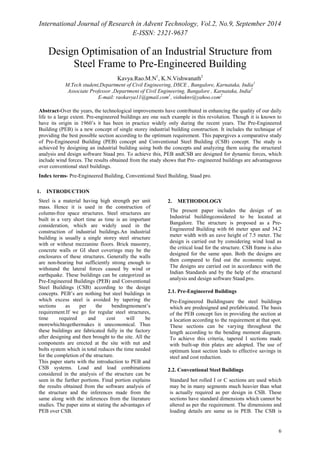
  • 4. International Journal of Research in Advent Technology, Vol.2, No.9, September 2014 E-ISSN: 2321-9637 9 Leeward -0.395 -0.044 -0.615 -0.264 Table 1(Continued) Gable end Windward -0.703 -0.351 0.439 0.791 Leeward -0.703 -0.351 -0.264 0.088 Frictional drag Windward and leeward 0.044 0.044 0.044 0.044 3.2.5. Load combinations: For the present study, various primary loads are considered as given below. (1) DEAD LOAD (2) LIVE LOAD (3) WIND LOAD 1 (4) WIND LOAD 2 (5) WIND LOAD 3 (6) WIND LOAD 4 For these primary loads, following are the combinations adopted for the analysis in both the concepts according to IS 800: 2007 (1) DL+LL (2) DL+WL1 (3) DL+WL2 (4) DL+WL3 (5) DL+WL4 (6) 1.5DL+1.5WL1 (7) 1.5DL+1.5WL2 (8) 1.5DL+1.5WL3 (9) 1.5DL+1.5WL4 3.3. Analysis by Staad pro: TheBending Moment Diagrams of the main frames of PEB and CSB by Staad pro are as shown in figure 2 and 3. Fig.2. Bending Moment Diagram of Main frame for PEB
  • 5. International Journal of Research in Advent Technology, Vol.2, No.9, September 2014 E-ISSN: 2321-9637 10 Fig.3. Bending Moment Diagram of Main frame for CSB 4. RESULTS AND DISCUSSION: Using the software Staad pro, the structure considered was analyzed and designed using both the PEB and CSB concept and obtained results are summarized as below in table 2 with reference to figure 2 and 3. Table 2.Summary of the results Sl.no. Parameter PEB CSB 1 Steel take off (kN) 1525 2410 2 Maximum moment (kNm) 670 705 3 Maximum shear force (kN) 326 414 4 Support reaction (kN) 155 197 5. SUMMARY AND CONCLUDING REMARKS: The paper contains the analysis and design concepts of PEB and also makes a comparison of the PEB and CSB. The results obtained from the study together with the literature studies show that the Pre- engineered buildings are advantageous over conventional steel buildings. The various inferences made from the study are as follows. (1) Steel take off : It can be seen that PEB’s reduce the steel used by 36% than that required for the CSB. This is the main factor for the cost reduction of the structure. Thus the material and cost savings can be done using PEB’s. (2) Moment and force: The bending and shear force of PEB are lesser than the CSB which in turn reduces the material required for the structure. The steel is provided as per the bending moment obtained at a particular section. (3) Support reaction: Support reaction for PEB is lesser compared to CSB. Hence heavier foundations can be avoided and thus the cost is reduced due to lighter foundations in the case of PEB. (4) Earthquake resistance: The lighter tapered sections offer better resistance to earthquake forces than the heavy frames of CSB in the earthquake zones. (5) Delivery of the material: Delivery of PEB components is done in around 6 to 8 weeks where as in the case of CSB it is more than 20 weeks. (6) Erection of the components: The PEB components are manufactured before bringing it to the site and therefore easily erected using nut and bolts at the site. No field work is required which makes the process of erection simpler. (7) Savings in cost: Savings in cost for PEB can be done in many ways such as savings in material, providing lighter foundation etc. Also the PEB’s are aesthetically pleasing at a lesser cost. Upto 30% cost reduction can be achieved using PEB. REFERENCES [1] IS: 875 (Part 1) – 1987: Code of Practice for Design Loads (Other Than Earthquake) for Buildings and Structures- Dead Loads [2]IS: 875 (Part 2) - 1987: Code of Practice for Design Loads (Other Than Earthquake) for Buildings And Structures- Live Loads [3]IS: 875 (Part 3) - 1987: Code of Practice for Design Loads (Other Than Earthquake) for Buildings and Structures- Wind Loads. [4] Dr. N. Subramanian, “Design of Steel Structures” [5] IS: 800 - 2007 :- General Construction In Steel - Code of Practice. [6]JatinD.Thakar,Prof.P.G.Patel,“Comparative Study of Pre-Engineered Steel Structure By Varying Width of Structure”, Applied Mechanics Department, L. D. College of Engineering, Ahmedabad. [7] C.M.Meera, “Pre-Engineered Building Design of an Industrial Warehouse",M.E. Structural Engineering, Regional Centre of Anna University, Coimbatore, India [8]Gurusharan Singh, “Introduction to Pre Engineered Buildings” [9] Aijaz Ahmad Zende, Prof. A. V. Kulkarni , AslamHutagia, "Comparative Study of Analysis and Design of Pre-Engineered Buildings and Conventional Frames" ,Civil EnggDept, B.L.D.E.A’s College of Engineering and Technology, India [10] Ms. Darshana P. Zoad (2012), “Evaluation of Pre-Engineering Structure Design by IS-800 as against Pre-Engineering Structure Design by AISC”, International Journal of Engineering Research & Technology (IJERT), Vol. 1, Issue 5. [11] Dr. N. Subramanian (2008), “Pre-engineered Buildings Selection of Framing System, Roofing and Wall Materials”, TheMasterbuilder, pp. 48-6. [12] SapnaKulshrestha (2012), ‘Designing of Pre-engineered Structures’, TheBuildotech India