1. International Journal of Research in Advent Technology, Vol.2, No.4, April 2014
E-ISSN: 2321-9637
16
Development and Fabrication of Alphanumeric Fuel
Level Indicator for Two Wheelers
Mr. Shakib Javed S. Sheikh1, Mr. Sumit D. Chambhare2, Prof.V.R.Gandhewar3, Prof. Mahesh S.
Gorde4
1Student, Final Year, Mech. Department, J.D.I.E.T., Yavatmal, Maharashtra, India, shakibjaved786@gmail.com
2 Student, Final Year, Mech. Department, J.D.I.E.T., Yavatmal, Maharashtra, India,
chambharesumit@gmail.com
3 Professor, Mech. Department, J.D.I.E.T., Yavatmal, Maharashtra, India, vivek.gandhewar@rediffmail.com
4Assistance Professor, Mech. Department, J.D.I.E.T., Yavatmal, Maharashtra, India,
gordemahesh7@rediffmail.com
Abstract- Digital fuel indicator is the fuel gauge in modern trends. As in the existing fuel indicator system
although they are digital but the value of amount of fuel available in tank of vehicle cannot be shows
correctly(exact value of the fuel amount).The digital(numeric) indicator will be used for the indication of the
amount of fuel in terms of numeric value i.e. in terms of digits or number. In this project we are going to study
the existing setup of the fuel indication system and fuel tanks that used and by redesigning the fuel tank we are
keen to establish the modern fuel indicator system that give us the exact suitable value of the fuel amount
present in the tank. The design software like CATIA, Solid edge, PRO-E for the redesigning of fuel tank and
electronics kit consisting microcontroller, ADC, LCD display for calibration of fuel amount in terms of numeric
value we are going to be used.
Index Terms- Digital fuel indicator, microcontroller, ADC, fuel tank.
1. INTRODUCTION
Nowadays the fuel indicator system for the two
wheelers are digital but they do not shows the exact
fuel amount which is present in the tank i.e. they
shows the amount of fuel in terms of bars and not in
numbers or digits like liter or milliliter. So this
problem is taken into consideration for our project
work of developing the digital (numeric) fuel
indicator system for two wheelers which shows exact
amount of fuel in terms of liter or milliliter. In this
project at firstly we surveyed the existing fuel
indicator system and fuel tanks of different bikes and
scooters. But during this survey we examined that the
design (shape and size) fuel tanks are in irregular
fashion. But due to irregular shape of the tanks there
were much complexities arises for the installation of
the electronics kit and level sensor which are used for
the calibration of fuel level/amount. So we redesign a
tank as a conceptual model in a regular shape like
rectangular by using design software like PRO-E.
Hence due to this regular design the installation of
electronics kit would became easier also this whole
system will gives us the fuel amount in terms of liter
or milliliter, for example 1L, 2L, 1.2L,500mL,
800mL.
2. HYPOTHESIS
While the vehicle is moving the fuel in the tank
fluctuates continuously, as this is our first attempt to
solve such a problem we made the assumption that the
vehicle is in a stable position for the indication of the
exact fuel amount in tank.
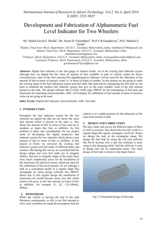
3. DESIGN AND FABRICATION
We have study and survey the different tanks of bikes
as well as scooters. Our electronics kit only work in a
regular shape like square, rectangles, circle etc. Hence
we design the tank in the rectangular shape. We
design the fuel tank by using the cad cam software
like Pro-E because now a day this software is more
using in the designing field. And the software is easy
to design and can be understand easily. Our main
design of fuel tank is shown in the figure below.
Fig 1: Conceptual design of fuel tank
2. International Journal of Research in Advent Technology, Vol.2, No.4, April 2014
E-ISSN: 2321-9637
17
Fig 2: Vertical cut sectional view of tank
4. ELECTRONICS COMPONENTS
POWER supply: -For our all IC we require 5 v d.c.
Supply, which can be generated by step down
transformer, full wave bridge rectifier, and filter
condenser and voltage regulator IC 7805.
TRANSFORMER:-We have used Step down
transformer as we have to generate 5 volts and 12
volts DC supply from the 230 volts input AC supply
so we have used 15 volts / 500 mA transformers
which mean its output will be 15 volts AC with
current rating of 500 mA.
RECTIFIER:-Rectifiers used to rectify the negative
half cycles of the output signal of the secondary of the
transformer. So at the input of the rectifier We have
AC signal with both positive and negative cycles and
at the output of the rectifier.
FILTER CAPACITOR:-Filter capacitor to remove
the AC signal from the output of rectifier. Filter
capacitor is used in order to remove ripples from the
pulsating DC and convert it to unregulated DC.
VOLTAGE REGULATOR:-Two separate voltage
regulators are used after the filter capacitor so as to
generate constant DC voltage supply of 5 volts and 12
volts. We have used 7805 and 7812 as a voltage
regulator.
MICROCONTROLLER:-
Design specification of Microcontroller 89S51
Features
• Compatible with MCS-51 (8051 series
microcontroller) products.
• 4k bytes of I system reprogrammable flash
memory.
• Endurance: 1000 write/erase cycles.
• Fully static operation: 0Hz to 24 MHz.
• Three level program memory lock.
• 128*8 bit internal ram.
• 32 programmable I/O lines.
• Two 16 bit timers/counters.
• Six interrupt sources.
• Programmable serial channel.
• Low power idle and power down modes.
Description:-
The AT89s52 is a low power, high performance
CMOS 8 bit microcomputer with 4k bytes of flash
programmable and erasable read only memory
(EEPROM). The device is manufactured using
Atmel’s high density non volatile memory technology
and is compatible with the industry standard MCS-51
instruction set and pin out. The on chip flash allows
program memory to be reprogrammed in system or by
a conventional non volatile memory programmer.
By combining a versatile 8 bit CPU with flash on a
monolithic chip, the Atmel AT89S51 is a powerful
microcomputer which provides a highly flexible and
cost effective solution to many embedded control
applications.
The AT89S52 provides the following standard
feature: 4k bytes of flash, 128 bytes of ram, 32 I/O
lines, two 16 bit timers/counters, five vector two-level
interrupt architecture, a full duplex serial port, and on-chip
oscillator and clock circuitry. In addition the
AT89S52 is designed with a static logic for operation
down to zero frequency and supports two selectable
power saving modes. The IDLE mode stops the CPU
while allowing the ram, timer/counter, serial port and
interrupts system to continue functioning. The power
down mode saves the ram contents but freezes the
oscillator disabling all other chip functions until the
next hardware reset.
Fig 3: PIN CONFIGURATION 40-lead PDIP
Pin description
1) VCC : Supply voltage : Pin no 40
2) GND : Ground : Pin no 20
3) XTAL1: Crystal terminal 1 : Pin no 18
4) XTAL2: Crystal terminal 2 : Pin no 19
5) RST : Reset Pin : Pin no 9
LCD interface to microcontroller:-
Liquid Crystal Display which is commonly known as
LCD is an Alphanumeric Display it means that it can
display Alphabets, Numbers as well as special
symbols thus LCD is a user friendly Display device
which can be used for displaying various messages
unlike seven segment display which can display only
numbers and some of the alphabets. The only
disadvantage of LCD over seven segment is that
3. International Journal of Research in Advent Technology, Vol.2, No.4, April 2014
E-ISSN: 2321-9637
18
seven segment is robust display and be visualized
from a longer distance as compared to LCD. Here we
have used 16 x 2 Alphanumeric Display which means
on this display we can display two lines with
maximum of 16 characters in one line.
This interface diagram shows us the connection of an
LCD to microcontroller.LCD consists of 8 data lines
which can be either a command or a data. An entire
port is used for sending data to the LCD by
microcontroller. 3 other pins are also used for
handshaking purposes.
Fig 4: LCD Interfacing
KEIL Microcontroller Programming Software:-
Keil has compiler designed specifically for
the 8051 microcontroller. Keil provides a broad range
of development tools like IDE (Integrated
Development environment), Project Manager,
Simulator, Debugger, C Cross Compiler.
Compilers are programs used to convert a
High Level Language source code (written in
assembly language or C language) into its object
code. Then a linker is used to create an absolute
object module suitable for your circuit.
8051 project development cycle: - these are the steps
to develop 8051 project using keil
· Create source files in C or assembly.
· Compile or assemble source files.
· Correct errors in source files.
· Link object files from compiler and
assembler.
· Test linked application.
5. MICROCONTROLLER PROGRAMMER
This Microcontroller Programmer we are using for
our project. This simple Microcontroller Programmer
will allow you to painlessly transfer hex programs to
most ATMEL Microcontroller microcontrollers
without sacrificing your budget and time. It is more
reliable than most other simple Microcontroller
programmers available out there and can be built in
very short amount of time.
Microcontroller programmer consists of in-circuit
serial programmer (dongle) and small PCB with a DIP
socket where you can fit your microcontroller and
have it quickly programmed.
You may also use this programmer as a
standalone in-circuit serial programmer that can be
used to conveniently program Microcontroller
microcontrollers without removing them from the
target circuit.
Entire Microcontroller programmer has been
build with using common parts and fits in the case of
the serial connector. The socket PCB has been created
to fit a 40-DIP Microcontroller 89s51 microcontroller,
but you can build a socket PCB for any other
Microcontroller out there. This Microcontroller
programmer is compatible with popular PonyProg
software that shows you a status bar of the
programming progress.
Fig 5: Serial connector
6. CONSTRUCTIO AND WORKING
Fuel indicator system consist of float with variable
resistance, ADC, uC, LCD display and buzzer.All this
components performe together to indicate the amount
of fuel in tank. A float with variable resistance is
installed in the tank at the base. Initially with no fuel
in tank the float is at its lowest position. 5V supply
from transformer is given to float rheostat.
When float is at its lowest position , rheostat
offers maximum resistance and no current passes. As
we start filling fuel in tank float starts rising up. Float
is attached to a vertical column with fulcrum and
supports rheostat. One end of the float is attached to
the rheostat, as float rises up results in varying
resistance, as resistance decreases flow of current
increases. The output current from the rheostat is
anolog signal which is feed to the anolog to digital
converter i.e. ADC.
ADC processes these anolog signal into
digital pulses. Output from ADC send to the
microcontroller, uC further processes digital signals
and send to the LCD display in the form of voltage .
This output voltage is calibrated in terms of volume of
petrol filled in tank in terms of liter or millileter.
Buzzer is also provided with system, this
buzzer is activated when fuel in the tank reaches
reserve level i.e. 0.5 L or 500 mL.After every 100 mL
reduction in fuel quantity periodic buzzer activates up
to zero position.
7. CONCLUSION:-
Hence we can conclude that the required goals and
objectives of our project have been achieved.
This project has built in us confidence that any
problem can be solved with sheer determination, hard
work and optimism. We feel that our product serves
something good to this world and we like to present it
4. International Journal of Research in Advent Technology, Vol.2, No.4, April 2014
E-ISSN: 2321-9637
19
before this prosperous world. By doing this project,
we were better able to understand the various facets of
doing an embedded system project which is emerging
as one of the most 'in demand' technologies right now.
REFERENCES
[1] Madhav Murthy, ICDMM 2014, ICDMM 39,
International Conference on Design,
Manufacturing and Mechatronics Design and
Fabrication of Digital fuel level indicator for two
wheeler.
[2] www.howstuffworks.com
[3] www.elecronicsforyou.com
[4] www.atmel.com
[5] www.datasheetlocator.com