SlideShare a Scribd company logo
1 of 10
Download to read offline
ArresterFacts 010 The Lightning Surge and Arresters
Copyright ArresterWorks 2008 Jonathan J. Woodworth Page1
ArresterFacts 017a
How to Select a
Transmission Line
Arrester
Rev 0 Feb 14, 2012
Prepared by
Jonathan Woodworth
Consulting Engineer
ArresterWorks
February 2012
ArresterWorks
ArresterFacts 017a How to Select a Transmission Line Arrester
© ArresterWorks 2012 Visit ArresterWorks ArresterFacts Library for other Resources Page2
How to Select a Transmission Line Arrester
Introduction
Selecting any arrester for an application can
be as easy as copying the catalog number
from the last inquiry your company
submitted or as difficult as running a full
blown system lightning/switching surge
study. The objective of this ArresterFacts is
to help the novice as well as the
experienced specifier of transmission line
arresters (TLA) by taking you through the
necessary steps in TLA selection. Along
with outlining the selection steps, it offers
rationale and guidance in each step. This is
the second ArresterFacts in a series on
transmission line arresters. The first in the
series is titled “What is a Transmission Line
Arrester” and can be found in my
ArresterFacts Library on
ArresterWorks.com. The third in the series
will focus on how to determine where to
install transmission line arresters.
What is a Line Arrester
Before we can define a line arrester, allow
me to clarify the name. This power system
component has been given several names
over the years. Recently in the IEC
community the term has been divided into
two more distinct terms, NGLA (non-gapped
line arrester) and EGLA (externally gapped
line arrester). In Cigre and other circles, it is
referred to as an LSA (line surge arrester).
In the IEEE regions, it is often called a TLA
(transmission line arrester) and LA (line
arrester or lightning arrester). This process
will focus on the NGLA and I will refer to this
Figure 1 Transmission Line Arrester Selection Process
ArresterFacts 017a How to Select a Transmission Line Arrester
© ArresterWorks 2012 Visit ArresterWorks ArresterFacts Library for other Resources Page3
arrester using this acronym. A future
ArresterFacts covering the EGLA selection
will be published later this year.
Even though the NGLA has been in
existence for many years, it is still a product
that is difficult to obtain information on.
If you check the IEC standards you will not
find any definition or reference to a NGLA or
transmission line arrester. In the IEEE
standards the term line arrester is defined
as follows: “A line arrester is a type of
arrester that is commonly applied to power
systems to reduce the risk of insulator
flashover during a lightning transient.” I
would like to add it may or may not be used
to protect the insulator from other types of
transients such as switching surges. A line
arrester is not generally used to protect any
equipment other than line insulators.
The NGLA Selection Process
The process of selecting an NGLA can be
very daunting for the novice and even for
the expert in power systems since it is done
so seldom. Both IEEE and IEC application
guides give versions of how to select a
standard arrester however neither one
covers the selection of a NGLA arrester.
The fundamental process of selecting an
arrester for a particular application is to
determine the characteristics of the system
and location where the arrester will be
installed, and then select the arrester
characteristics that will meet the
requirements of the application. To facilitate
the selection of an NGLA, I have configured
a clear straightforward 6-step process that
considers all issues. Using the process as
shown in Figure 1 you can see that for each
step in the selection process, the system
parameters are determined first and then
the corresponding arrester parameters are
selected.
Step 1
Selecting the Arrester Type
The selection process begins with choosing
the arrester type that appears to best meet
the needs of the application. Even though
this is fundamentally one of the most
important steps it is routinely left out of
procedures in the standards. For example
when the objective is to select an arrester
for a 33kV sub-transmission line, there is no
need to think about Class 5 arresters that
would ordinarily be installed on a 400-800kV
lines. This initial choice can easily be
modified if an issue arises in upcoming
steps.
The important actions of this step are:
1. Identify the approximate location of the
arrester in the system.
2. Review available arresters and their
characteristics data.
3. Make the Initial Selection of the Target
Arrester Family
Another important consideration when
selecting an arrester to be installed on a
transmission line or sub-transmission line is
to consider the housing type. Whenever
possible, first priority should be given to the
polymer housed type arresters as shown in
Figure 7, since they often are lighter and
more easily mounted on a transmission line
than porcelain housed arresters.
Step 2
Selecting the AC Rating
Since most arresters are energized with an
AC voltage throughout their life, this step is
critical and cannot be skipped. An incorrect
AC rating could result in premature arrester
failure and a system outage. The MCOV or
Uc of a TLA is the AC rating of concern.
This is the maximum AC voltage that can be
applied continuously across the terminals of
the arrester. For NGLAs this AC rating
must be checked for temporary overvoltage
(TOV) withstand capability and may be
adjusted higher to meet the TOV
requirements. The initially selected AC
rating of an NGLA is generally a minimum
ArresterFacts 017a How to Select a Transmission Line Arrester
© ArresterWorks 2012 Visit ArresterWorks ArresterFacts Library for other Resources Page4
value and in subsequent steps, it may be
increased to meet other constraints.
Significant considerations in this step are:
2.1 Determine maximum steady state
system line-ground voltage.
This is defined as the nominal phase to
phase voltage divided by 1.73 times the
regulation error. For example, on a 760kV
transmission system, the nominal system
phase to phase voltage is 760kV therefore
the line to earth voltage would be 440kV.
Since all systems have some regulation
error, this too must be taken into
consideration. If the regulation error is 10%,
then for example, on the above system, the
line to ground voltage could be 440x 1.10 =
485kV. The MCOV/Uc of an arrester for
this system, at a minimum, should be 485kV
before TOV is taken into account.
2.2 Select an arrester MCOV/Uc that is
equal or greater than the voltage
determined in 2.1:
A general IEC practice is to select a Uc that
is 1.05 times the highest continuous line to
earth voltage. The IEEE practice is that
MCOV should be ≥ than the level in step
2.1. Since this arrester is only eliminating
insulator flashover, another 10% can be
added to this level to reduce the energy the
arrester adsorbs during a switching surge if
desired.
2.3 Determine the maximum amplitude
and duration of potential overvoltages
on the system:
This is one of the most difficult steps in
selecting any arrester. The difficulty arises
from the fact that determining the amplitude
and duration of temporary overvoltage
events is not an easy task. For arrester
selection, the overvoltages of interest are
ones that occur during an earth fault on the
system. During an earth fault on a 3 phase
power system, the voltage on the unfaulted
phase will rise to levels that can easily
damage an arrester if not promptly removed
by a breaker operation. The neutral
earthing configuration is the determining
factor in calculating the amplitude of the
overvoltage during this type of fault on the
system.
Figure 2 Neutral configurations of Importance
Figure 2 shows examples of system
configurations of importance.
For distribution systems, the worst case
amplitude can be determined by the
earthing configuration but seldom is the
duration clearly understood. Due to the lack
of data for these applications, the durations
are estimated based on the system type.
Figure 3 gives an overview of the typical
worst case scenarios.
Figure 3 Typical TOV Amplitudes and Duration
For transmission lines and substations, the
amplitude and duration are much better
ArresterFacts 017a How to Select a Transmission Line Arrester
© ArresterWorks 2012 Visit ArresterWorks ArresterFacts Library for other Resources Page5
understood and the worst case scenario is
seldom used. The systems are most often
modeled and the potential TOV levels and
durations are available from these fault
current studies. Use these amplitudes and
durations to compare to the arrester TOV
withstand curves in the next step as shown
in Figure 4.
2.4 Check that the arrester selected in
2.2 can withstand the overvoltages
determined in 2.3 using the arrester TOV
curve.
Once the arrester MCOV/Uc rating is
selected, the characteristics of that arrester
will then be tested against other constraints
in the selection process. If the other
constraints require an increase in the Uc or
Ur to meet their requirements, then the AC
rating in this step will be overridden.
Figure 4 Arrester TOV Curve
ArresterFacts 017a How to Select a Transmission Line Arrester
© ArresterWorks 2012 Visit ArresterWorks ArresterFacts Library for other Resources Page6
Step 3
Check the Margin of Protection
The fundamental purpose of a transmission
line arrester is to reduce the risk of insulator
flashover due to either switching surges
and/or lightning surges. The margin of
protection is a standard means of evaluating
the level of risk of this flashover. If the
arrester clamps the voltage at a fraction of
the Critical Flashover Voltage (CFO) of an
insulator, then the risk of insulator flashover
is quite low. Neither the IEC or IEEE
standards make a recommendation as to
what is adequate margin of protection for
line insulators. They do recommend that the
arrester residual voltage not be more than
80-85% of insulator BIL in stations. A
graphic representation of margin of
protection calculations is shown in Figure 5.
The fundamental parts to the step in the
Margin of Protection selection process are:
3.1 Determine the Insulation Withstand
Characteristics
3.1.1 LI CFO (LIWV)
3.1.2 SI CFO (SIWV)
3.2 Determine Arrester Protective
Characteristics
3.2.1 Lightning Protective Level (LIPL)
3.2.2 Switching Protective Level (SIPL)
3.3 Determine if there is any Lead Length
Effect
3.4 Calculate Margin of Protection
3.4.1 Lightning Protection Margin
3.4.2 Switching Protective Margin
Figure 5 Arrester Insulation Coordination Formula
ArresterFacts 017a How to Select a Transmission Line Arrester
© ArresterWorks 2012 Visit ArresterWorks ArresterFacts Library for other Resources Page7
Step 4 Check Energy
Handling Capabilities
This is another very important part of the
selection procedure of an NGLA. During
this consideration, the purpose of the
arrester installation must be well
understood.
Considerations that need to be taken into
account in this part of the selection are:
System with OHGW
If the arrester is to be used on a system that
is equipped with an overhead ground wire
(OHGW), the energy requirements of the
arrester are much lower than if it is not
equipped with the OHGW. This is due to
the fact that most of the lightning current
during a stroke is shunted to ground via the
down conductor and only 10-20% of the
lightning current flows through the arrester
on to the phase. If the footing resistance of
the tower is quite high, more current will be
diverted through the arrester and into the
phase but in the worst case, most will still
flow to earth instead of on to the conductor.
For configurations less than 300kV system
voltage, a distribution class arrester is all
that is needed for ample reliability and
protection. Using a distribution class
arrester for lightning protection where little
switching surge energy is available is
standard practice in the US and Japan. If a
more conservative rating is desired for this
configuration, a lower station class arrester
can be used, but is not necessary. For
systems above 300kV, the class of arrester
will likely be higher than a distribution class
arrester due to switching surge energy
demands.
Systems without OHGW
If the NGLA application is on a system
without an OHGW, the full lightning stroke is
likely to pass through the arrester. Since a
very low system outage rate is desired, then
it is suggested that an Intermediate or
Station Class arrester be used to protect
this type of system. Distribution arresters
are an option of course, but to ensure that
the arrester has an extremely low risk of
failure due to a high current stroke, it is
better to use an Intermediate or Station
Arrester.
Switching Surge Energy Considerations
If the NGLA application is to control surges
generated during switching events, the
potential switching surge energy of the
system needs to be calculated and
compared to the energy handling
capabilities of the arrester. For distribution
systems and transmission systems below
230kV, the potential switching surge energy
of the system does not exceed that of a
Distribution class arrester. Therefore,
when considering switching surge control on
these systems, there is no need to consider
higher energy ratings.
For systems above 230kV, a precise energy
dissipation requirement can be determined
using transient analysis software or an
estimate can be made using simple
formulas found in either IEC 60099-5 or
IEEE C62.22. IEC 60071-2 offers an
excellent estimation of what magnitude of
switching surges to expect on power
systems from normal energization
operations. According to this standard,
switching surges can range from 1.2pu to
3.5pu depending on the system and action
during the event. This translates into
energies between 4-10kJ/kV MCOV/Uc
which is well within the range of most
station arrester designs.
IEC Lightning Impulse Discharge
Capability Test
For arresters applied to systems up to 52kV,
the High Current Impulse capability is the
only means of classifying the lightning
impulse capability. For all distribution-10kA
arresters, the designs must be capable of
withstanding 100kA 2x10uS impulse at least
2 times. For 5kA arresters, this high
current capability is reduced to 65kA.
For arresters applied to systems 52kV and
above, a special test requirement and
withstand capability is available to the
specifier of arresters. Since 2006, all line
surge arresters applied to systems above
52kV are required to be tested per the
ArresterFacts 017a How to Select a Transmission Line Arrester
© ArresterWorks 2012 Visit ArresterWorks ArresterFacts Library for other Resources Page8
Lightning Impulse Discharge Capability test
outlined in IEC 60099-4 Annex N. This new
lightning impulse capability test uniquely
tests the arrester with an impulse that crests
in 200uS and is sinusoidal in shape. This
test is unique because the arrester does not
pass or fail, they just fall into one of many
available categories of withstand. A further
unique feature of this test is that the arrester
withstand can be measured in either energy
(joules) or in Charge (A-Seconds). A
Distribution type arrester can have ratings
as high as .5 coulombs and a Station Class
arrester approximately equal to 3.6
coulombs of charge transfer. When
selecting an arrester for line protection
above 52kV, this characteristic should be
considered.
Step 5
Check Failure Modes
This is another important arrester selection
steps for an NGLA if the arrester is located
near highways or occupied buildings. If
the arrester is overloaded, it often becomes
a short circuit to the system to which it is
applied. If this happens, the power system
will supply all potential fault current to the
circuit including the arrester. If a shorted
arrester experiences more power-frequency
fault current than it was designed to handle,
it could eject very hot components at
significant distance and velocity. A
fragmenting overload is a highly undesirable
event. To insure that this type of overload
event does not occur, the short circuit
current withstand capability of the NGLA
needs to be higher than the available fault
current of the system. The short circuit
rating of all arresters is found on the
nameplate of the arrester and in the
manufacturing literature.
Typically distribution systems can supply
only 10kA fault current, occasionally higher.
Therefore the NGLA for distribution systems
needs to be 10-15kA maximum. For
transmission lines above 50kV, the
available fault current can be as high as
65kA with grounded systems, and low as a
Figure 6 Acceptable Failure Mode
Figure 7 Undesirable Failure Mode
ArresterFacts 017a How to Select a Transmission Line Arrester
© ArresterWorks 2012 Visit ArresterWorks ArresterFacts Library for other Resources Page9
few hundred amps for impedance grounded
or floating delta systems. When an
arrester has been subjected to an overload,
it should look similar to Figure 6 when the
event is over. However if the system
ground fault current exceeds the rating of
the arrester what is seen in Figure 7 may
occur which is highly undesirable.
The user needs to know the available fault
current on the system to which the arrester
is to be mounted. This data is readily
available from the relay or system analysis
personnel.
Step 6
Mounting Considerations
Line surge arresters are stressed physically
more than any other arrester. This is
because they are mounted on or near
towers that are very exposed to the
elements. Vibration, wind, torque, impact
stress and animal abuse are the main
reasons for the high stresses. For these
afore mentioned reasons the selection of
mounting components is very important and
often times the most difficult part of NGLA
selection. Also since there are so many
tower configurations the mounting
requirement for each installation is unique.
The following are specific and important
mounting features to consider.
Vibration: Presently there are no standard
tests to determine if an NGLA can withstand
vibrations found at tower tops and on
conductors. It is advised that the user
discuss this with suppliers.
Disconnector Strength: If the NGLA is
equipped with a disconnector it is imperative
that the mounting does not stress this
component beyond its capability. If the
arrester is to be mounted with the
disconnector in any way other than the
weight of the ground lead, then this should
be discussed with the supplier. Some
disconnectors are designed for this type of
stress, but not all of them.
Lead Swing: This is one of the biggest
reasons for NGLA issues since a swinging
lead not only can break itself, but it can also
transfer the mechanical stresses to the
other components. Again there is no
standard for this issue so it must be
discussed with the supplier. One solution
that is often used is to string the lead
through a chain that reduces the frequency
and amplitude of the swing as well as
reduces the direct strain on the lead. Figure
7 shows this arrangement.
Bird Droppings: Just like an insulator, if
the NGLA is to be mounted where it is
subject to bird droppings, use the same
precautions you would if it was an insulator.
BIL Restoration: If the NGLA had been
overloaded and failed, it should be mounted
so that it will disconnect allowing full system
BIL to be restored. This is accomplished by
mounting the arrester so that it or its lead
will swing out of the way if it becomes a
short circuit.
Figure 7 Lead Reinforcement with a chain
PhotoComplimentsofHubbellPowerSystems
ArresterFacts 017a How to Select a Transmission Line Arrester
© ArresterWorks 2012 Visit ArresterWorks ArresterFacts Library for other Resources Page10
Summary
Once you have completed all 6 steps of the
NGLA selection process, you will likely have
the optimum arrester chosen for the
application. There may be times that this
process will need to be completed several
times before the final arrester is chosen.
When the arresters are installed, you will be
pleased with the results. NGLAs are major
reliability enhancers for power systems.
**************
____________________________________________________________________________________
ArresterFacts Usage
ArresterFacts are Copyrighted documents intended for the
education of arrester users and stakeholders. If you choose to
copy any part of this document for teaching purposes you have
my permission, however please give ArresterWorks proper
credit.
Thank you for using www.ArresterWorks.com as a source of
information on high voltage surge arresters.
Jonathan Woodworth
Principal Consultant
ArresterWorks

More Related Content

What's hot

Pd Maintenance
Pd MaintenancePd Maintenance
Pd Maintenancedwessin
 
Protection schemes and zones
Protection schemes and zonesProtection schemes and zones
Protection schemes and zonesSlides Hub
 
distribution system fault mangement
distribution system fault mangementdistribution system fault mangement
distribution system fault mangementManjunath Ds
 
Power System Protection course - Part I
Power System Protection course - Part IPower System Protection course - Part I
Power System Protection course - Part ISlides Hub
 
RELAY CO-ORDINATION WITH FAULT CALCULATION
RELAY CO-ORDINATION WITH FAULT CALCULATIONRELAY CO-ORDINATION WITH FAULT CALCULATION
RELAY CO-ORDINATION WITH FAULT CALCULATIONMd Sarowar Alam
 
Electrical Power Protection & Relay Coordination Engineering
Electrical Power Protection & Relay Coordination EngineeringElectrical Power Protection & Relay Coordination Engineering
Electrical Power Protection & Relay Coordination EngineeringDEVELOP
 
Fundamentals of Microprocessor Based Relays
Fundamentals of Microprocessor Based RelaysFundamentals of Microprocessor Based Relays
Fundamentals of Microprocessor Based Relaysmichaeljmack
 
Distance protection scheme for transmission line using back propagation neura...
Distance protection scheme for transmission line using back propagation neura...Distance protection scheme for transmission line using back propagation neura...
Distance protection scheme for transmission line using back propagation neura...eSAT Publishing House
 
PROTECTION COORDINATION OF DISTRIBUTION SYSTEMS EQUIPPED WITH DISTRIBUTED GEN...
PROTECTION COORDINATION OF DISTRIBUTION SYSTEMS EQUIPPED WITH DISTRIBUTED GEN...PROTECTION COORDINATION OF DISTRIBUTION SYSTEMS EQUIPPED WITH DISTRIBUTED GEN...
PROTECTION COORDINATION OF DISTRIBUTION SYSTEMS EQUIPPED WITH DISTRIBUTED GEN...ELELIJ
 
Protection primer
Protection primerProtection primer
Protection primerluonglt
 
protection and relay scheme
protection and relay schemeprotection and relay scheme
protection and relay schemeinfosaneeshss
 
Power System Protection basics
Power System Protection basicsPower System Protection basics
Power System Protection basicsRajan Singh Tanwar
 
Protective relaying and power quality
Protective relaying and power qualityProtective relaying and power quality
Protective relaying and power qualityfariamunim
 

What's hot (20)

auto-reclosure
auto-reclosureauto-reclosure
auto-reclosure
 
Auto reclosers
Auto reclosersAuto reclosers
Auto reclosers
 
Pd Maintenance
Pd MaintenancePd Maintenance
Pd Maintenance
 
Protection schemes and zones
Protection schemes and zonesProtection schemes and zones
Protection schemes and zones
 
Protective Relay by Shamim Reza
Protective Relay  by Shamim RezaProtective Relay  by Shamim Reza
Protective Relay by Shamim Reza
 
HV Circuit Breaker Testing
HV Circuit Breaker TestingHV Circuit Breaker Testing
HV Circuit Breaker Testing
 
distribution system fault mangement
distribution system fault mangementdistribution system fault mangement
distribution system fault mangement
 
Power System Protection course - Part I
Power System Protection course - Part IPower System Protection course - Part I
Power System Protection course - Part I
 
RELAY CO-ORDINATION WITH FAULT CALCULATION
RELAY CO-ORDINATION WITH FAULT CALCULATIONRELAY CO-ORDINATION WITH FAULT CALCULATION
RELAY CO-ORDINATION WITH FAULT CALCULATION
 
Electrical Power Protection & Relay Coordination Engineering
Electrical Power Protection & Relay Coordination EngineeringElectrical Power Protection & Relay Coordination Engineering
Electrical Power Protection & Relay Coordination Engineering
 
Time current curves
Time current curvesTime current curves
Time current curves
 
Fundamentals of Microprocessor Based Relays
Fundamentals of Microprocessor Based RelaysFundamentals of Microprocessor Based Relays
Fundamentals of Microprocessor Based Relays
 
Distance protection scheme for transmission line using back propagation neura...
Distance protection scheme for transmission line using back propagation neura...Distance protection scheme for transmission line using back propagation neura...
Distance protection scheme for transmission line using back propagation neura...
 
Overcurrent Protection
Overcurrent ProtectionOvercurrent Protection
Overcurrent Protection
 
PROTECTION COORDINATION OF DISTRIBUTION SYSTEMS EQUIPPED WITH DISTRIBUTED GEN...
PROTECTION COORDINATION OF DISTRIBUTION SYSTEMS EQUIPPED WITH DISTRIBUTED GEN...PROTECTION COORDINATION OF DISTRIBUTION SYSTEMS EQUIPPED WITH DISTRIBUTED GEN...
PROTECTION COORDINATION OF DISTRIBUTION SYSTEMS EQUIPPED WITH DISTRIBUTED GEN...
 
Protection primer
Protection primerProtection primer
Protection primer
 
Protection primer
Protection primerProtection primer
Protection primer
 
protection and relay scheme
protection and relay schemeprotection and relay scheme
protection and relay scheme
 
Power System Protection basics
Power System Protection basicsPower System Protection basics
Power System Protection basics
 
Protective relaying and power quality
Protective relaying and power qualityProtective relaying and power quality
Protective relaying and power quality
 

Similar to How to select a transmission line arrester

Short circuit current calculations
Short circuit current calculationsShort circuit current calculations
Short circuit current calculationsRonald Santos
 
IRJET- Overhead Line Protection with Automatic Switch by using PLC Automation
IRJET- Overhead Line Protection with Automatic Switch by using PLC AutomationIRJET- Overhead Line Protection with Automatic Switch by using PLC Automation
IRJET- Overhead Line Protection with Automatic Switch by using PLC AutomationIRJET Journal
 
a26e8dedece825e530c50c1240886cf0.pptx
a26e8dedece825e530c50c1240886cf0.pptxa26e8dedece825e530c50c1240886cf0.pptx
a26e8dedece825e530c50c1240886cf0.pptxTesloachKongGilo
 
Transfguide transformer protection application guide
Transfguide transformer protection application guideTransfguide transformer protection application guide
Transfguide transformer protection application guidePrasad RVS
 
Review on Different Techniques for Differential Protection of Power Transformer
Review on Different Techniques for Differential Protection of Power TransformerReview on Different Techniques for Differential Protection of Power Transformer
Review on Different Techniques for Differential Protection of Power TransformerIRJET Journal
 
Pq unit ii
Pq unit iiPq unit ii
Pq unit iivenki249
 
project presentation on "THMC"
project presentation on "THMC"project presentation on "THMC"
project presentation on "THMC"Teja venkat
 
RCBU-2-Arc-Flash-Protection_Key_Considerations_for_Selection
RCBU-2-Arc-Flash-Protection_Key_Considerations_for_SelectionRCBU-2-Arc-Flash-Protection_Key_Considerations_for_Selection
RCBU-2-Arc-Flash-Protection_Key_Considerations_for_SelectionKieron King
 
Power transformer maintenance
Power transformer maintenancePower transformer maintenance
Power transformer maintenanceLucian Lazar
 
Compensation of Balanced and Unbalanced Voltage Disturbance using SRF Control...
Compensation of Balanced and Unbalanced Voltage Disturbance using SRF Control...Compensation of Balanced and Unbalanced Voltage Disturbance using SRF Control...
Compensation of Balanced and Unbalanced Voltage Disturbance using SRF Control...IRJET Journal
 
Power_System_Protection Lecture-1.pdf
Power_System_Protection Lecture-1.pdfPower_System_Protection Lecture-1.pdf
Power_System_Protection Lecture-1.pdfYogeshGairola2
 
Electric protection
Electric protectionElectric protection
Electric protectionVinay Gupta
 
Remediation of Old Substations for Arc Flash hazard
Remediation of Old Substations for Arc Flash hazardRemediation of Old Substations for Arc Flash hazard
Remediation of Old Substations for Arc Flash hazardIJAPEJOURNAL
 
Auto Reset on Temporary Fault Otherwise Permanent Trip in Three Phase Transmi...
Auto Reset on Temporary Fault Otherwise Permanent Trip in Three Phase Transmi...Auto Reset on Temporary Fault Otherwise Permanent Trip in Three Phase Transmi...
Auto Reset on Temporary Fault Otherwise Permanent Trip in Three Phase Transmi...IRJET Journal
 
Monitoring of Distribution Transformer Parameters Using Plc
Monitoring of Distribution Transformer Parameters Using PlcMonitoring of Distribution Transformer Parameters Using Plc
Monitoring of Distribution Transformer Parameters Using PlcIRJET Journal
 
IRJET - Automated Monitoring Test Rig for Circuit Breaker Operation
IRJET -  	  Automated Monitoring Test Rig for Circuit Breaker OperationIRJET -  	  Automated Monitoring Test Rig for Circuit Breaker Operation
IRJET - Automated Monitoring Test Rig for Circuit Breaker OperationIRJET Journal
 

Similar to How to select a transmission line arrester (20)

Short circuit current calculations
Short circuit current calculationsShort circuit current calculations
Short circuit current calculations
 
IRJET- Overhead Line Protection with Automatic Switch by using PLC Automation
IRJET- Overhead Line Protection with Automatic Switch by using PLC AutomationIRJET- Overhead Line Protection with Automatic Switch by using PLC Automation
IRJET- Overhead Line Protection with Automatic Switch by using PLC Automation
 
a26e8dedece825e530c50c1240886cf0.pptx
a26e8dedece825e530c50c1240886cf0.pptxa26e8dedece825e530c50c1240886cf0.pptx
a26e8dedece825e530c50c1240886cf0.pptx
 
Transformer guide
Transformer guideTransformer guide
Transformer guide
 
Transfguide transformer protection application guide
Transfguide transformer protection application guideTransfguide transformer protection application guide
Transfguide transformer protection application guide
 
Review on Different Techniques for Differential Protection of Power Transformer
Review on Different Techniques for Differential Protection of Power TransformerReview on Different Techniques for Differential Protection of Power Transformer
Review on Different Techniques for Differential Protection of Power Transformer
 
Pq unit ii
Pq unit iiPq unit ii
Pq unit ii
 
project presentation on "THMC"
project presentation on "THMC"project presentation on "THMC"
project presentation on "THMC"
 
RCBU-2-Arc-Flash-Protection_Key_Considerations_for_Selection
RCBU-2-Arc-Flash-Protection_Key_Considerations_for_SelectionRCBU-2-Arc-Flash-Protection_Key_Considerations_for_Selection
RCBU-2-Arc-Flash-Protection_Key_Considerations_for_Selection
 
Power transformer maintenance
Power transformer maintenancePower transformer maintenance
Power transformer maintenance
 
Power transformer maintenance
Power transformer maintenancePower transformer maintenance
Power transformer maintenance
 
Compensation of Balanced and Unbalanced Voltage Disturbance using SRF Control...
Compensation of Balanced and Unbalanced Voltage Disturbance using SRF Control...Compensation of Balanced and Unbalanced Voltage Disturbance using SRF Control...
Compensation of Balanced and Unbalanced Voltage Disturbance using SRF Control...
 
Pe3426652670
Pe3426652670Pe3426652670
Pe3426652670
 
Power_System_Protection Lecture-1.pdf
Power_System_Protection Lecture-1.pdfPower_System_Protection Lecture-1.pdf
Power_System_Protection Lecture-1.pdf
 
Electric protection
Electric protectionElectric protection
Electric protection
 
Remediation of Old Substations for Arc Flash hazard
Remediation of Old Substations for Arc Flash hazardRemediation of Old Substations for Arc Flash hazard
Remediation of Old Substations for Arc Flash hazard
 
Auto Reset on Temporary Fault Otherwise Permanent Trip in Three Phase Transmi...
Auto Reset on Temporary Fault Otherwise Permanent Trip in Three Phase Transmi...Auto Reset on Temporary Fault Otherwise Permanent Trip in Three Phase Transmi...
Auto Reset on Temporary Fault Otherwise Permanent Trip in Three Phase Transmi...
 
Monitoring of Distribution Transformer Parameters Using Plc
Monitoring of Distribution Transformer Parameters Using PlcMonitoring of Distribution Transformer Parameters Using Plc
Monitoring of Distribution Transformer Parameters Using Plc
 
D04522631
D04522631D04522631
D04522631
 
IRJET - Automated Monitoring Test Rig for Circuit Breaker Operation
IRJET -  	  Automated Monitoring Test Rig for Circuit Breaker OperationIRJET -  	  Automated Monitoring Test Rig for Circuit Breaker Operation
IRJET - Automated Monitoring Test Rig for Circuit Breaker Operation
 

Recently uploaded

Top Rated Pune Call Girls Budhwar Peth ⟟ 6297143586 ⟟ Call Me For Genuine Se...
Top Rated  Pune Call Girls Budhwar Peth ⟟ 6297143586 ⟟ Call Me For Genuine Se...Top Rated  Pune Call Girls Budhwar Peth ⟟ 6297143586 ⟟ Call Me For Genuine Se...
Top Rated Pune Call Girls Budhwar Peth ⟟ 6297143586 ⟟ Call Me For Genuine Se...Call Girls in Nagpur High Profile
 
(ANJALI) Dange Chowk Call Girls Just Call 7001035870 [ Cash on Delivery ] Pun...
(ANJALI) Dange Chowk Call Girls Just Call 7001035870 [ Cash on Delivery ] Pun...(ANJALI) Dange Chowk Call Girls Just Call 7001035870 [ Cash on Delivery ] Pun...
(ANJALI) Dange Chowk Call Girls Just Call 7001035870 [ Cash on Delivery ] Pun...ranjana rawat
 
APPLICATIONS-AC/DC DRIVES-OPERATING CHARACTERISTICS
APPLICATIONS-AC/DC DRIVES-OPERATING CHARACTERISTICSAPPLICATIONS-AC/DC DRIVES-OPERATING CHARACTERISTICS
APPLICATIONS-AC/DC DRIVES-OPERATING CHARACTERISTICSKurinjimalarL3
 
High Profile Call Girls Nagpur Meera Call 7001035870 Meet With Nagpur Escorts
High Profile Call Girls Nagpur Meera Call 7001035870 Meet With Nagpur EscortsHigh Profile Call Girls Nagpur Meera Call 7001035870 Meet With Nagpur Escorts
High Profile Call Girls Nagpur Meera Call 7001035870 Meet With Nagpur EscortsCall Girls in Nagpur High Profile
 
(RIA) Call Girls Bhosari ( 7001035870 ) HI-Fi Pune Escorts Service
(RIA) Call Girls Bhosari ( 7001035870 ) HI-Fi Pune Escorts Service(RIA) Call Girls Bhosari ( 7001035870 ) HI-Fi Pune Escorts Service
(RIA) Call Girls Bhosari ( 7001035870 ) HI-Fi Pune Escorts Serviceranjana rawat
 
Processing & Properties of Floor and Wall Tiles.pptx
Processing & Properties of Floor and Wall Tiles.pptxProcessing & Properties of Floor and Wall Tiles.pptx
Processing & Properties of Floor and Wall Tiles.pptxpranjaldaimarysona
 
UNIT-V FMM.HYDRAULIC TURBINE - Construction and working
UNIT-V FMM.HYDRAULIC TURBINE - Construction and workingUNIT-V FMM.HYDRAULIC TURBINE - Construction and working
UNIT-V FMM.HYDRAULIC TURBINE - Construction and workingrknatarajan
 
HARMONY IN THE NATURE AND EXISTENCE - Unit-IV
HARMONY IN THE NATURE AND EXISTENCE - Unit-IVHARMONY IN THE NATURE AND EXISTENCE - Unit-IV
HARMONY IN THE NATURE AND EXISTENCE - Unit-IVRajaP95
 
Call for Papers - African Journal of Biological Sciences, E-ISSN: 2663-2187, ...
Call for Papers - African Journal of Biological Sciences, E-ISSN: 2663-2187, ...Call for Papers - African Journal of Biological Sciences, E-ISSN: 2663-2187, ...
Call for Papers - African Journal of Biological Sciences, E-ISSN: 2663-2187, ...Christo Ananth
 
UNIT-II FMM-Flow Through Circular Conduits
UNIT-II FMM-Flow Through Circular ConduitsUNIT-II FMM-Flow Through Circular Conduits
UNIT-II FMM-Flow Through Circular Conduitsrknatarajan
 
Introduction and different types of Ethernet.pptx
Introduction and different types of Ethernet.pptxIntroduction and different types of Ethernet.pptx
Introduction and different types of Ethernet.pptxupamatechverse
 
(SHREYA) Chakan Call Girls Just Call 7001035870 [ Cash on Delivery ] Pune Esc...
(SHREYA) Chakan Call Girls Just Call 7001035870 [ Cash on Delivery ] Pune Esc...(SHREYA) Chakan Call Girls Just Call 7001035870 [ Cash on Delivery ] Pune Esc...
(SHREYA) Chakan Call Girls Just Call 7001035870 [ Cash on Delivery ] Pune Esc...ranjana rawat
 
OSVC_Meta-Data based Simulation Automation to overcome Verification Challenge...
OSVC_Meta-Data based Simulation Automation to overcome Verification Challenge...OSVC_Meta-Data based Simulation Automation to overcome Verification Challenge...
OSVC_Meta-Data based Simulation Automation to overcome Verification Challenge...Soham Mondal
 
SPICE PARK APR2024 ( 6,793 SPICE Models )
SPICE PARK APR2024 ( 6,793 SPICE Models )SPICE PARK APR2024 ( 6,793 SPICE Models )
SPICE PARK APR2024 ( 6,793 SPICE Models )Tsuyoshi Horigome
 
Software Development Life Cycle By Team Orange (Dept. of Pharmacy)
Software Development Life Cycle By  Team Orange (Dept. of Pharmacy)Software Development Life Cycle By  Team Orange (Dept. of Pharmacy)
Software Development Life Cycle By Team Orange (Dept. of Pharmacy)Suman Mia
 
IMPLICATIONS OF THE ABOVE HOLISTIC UNDERSTANDING OF HARMONY ON PROFESSIONAL E...
IMPLICATIONS OF THE ABOVE HOLISTIC UNDERSTANDING OF HARMONY ON PROFESSIONAL E...IMPLICATIONS OF THE ABOVE HOLISTIC UNDERSTANDING OF HARMONY ON PROFESSIONAL E...
IMPLICATIONS OF THE ABOVE HOLISTIC UNDERSTANDING OF HARMONY ON PROFESSIONAL E...RajaP95
 
UNIT-III FMM. DIMENSIONAL ANALYSIS
UNIT-III FMM.        DIMENSIONAL ANALYSISUNIT-III FMM.        DIMENSIONAL ANALYSIS
UNIT-III FMM. DIMENSIONAL ANALYSISrknatarajan
 
Call Girls in Nagpur Suman Call 7001035870 Meet With Nagpur Escorts
Call Girls in Nagpur Suman Call 7001035870 Meet With Nagpur EscortsCall Girls in Nagpur Suman Call 7001035870 Meet With Nagpur Escorts
Call Girls in Nagpur Suman Call 7001035870 Meet With Nagpur EscortsCall Girls in Nagpur High Profile
 
Introduction to Multiple Access Protocol.pptx
Introduction to Multiple Access Protocol.pptxIntroduction to Multiple Access Protocol.pptx
Introduction to Multiple Access Protocol.pptxupamatechverse
 

Recently uploaded (20)

Top Rated Pune Call Girls Budhwar Peth ⟟ 6297143586 ⟟ Call Me For Genuine Se...
Top Rated  Pune Call Girls Budhwar Peth ⟟ 6297143586 ⟟ Call Me For Genuine Se...Top Rated  Pune Call Girls Budhwar Peth ⟟ 6297143586 ⟟ Call Me For Genuine Se...
Top Rated Pune Call Girls Budhwar Peth ⟟ 6297143586 ⟟ Call Me For Genuine Se...
 
(ANJALI) Dange Chowk Call Girls Just Call 7001035870 [ Cash on Delivery ] Pun...
(ANJALI) Dange Chowk Call Girls Just Call 7001035870 [ Cash on Delivery ] Pun...(ANJALI) Dange Chowk Call Girls Just Call 7001035870 [ Cash on Delivery ] Pun...
(ANJALI) Dange Chowk Call Girls Just Call 7001035870 [ Cash on Delivery ] Pun...
 
APPLICATIONS-AC/DC DRIVES-OPERATING CHARACTERISTICS
APPLICATIONS-AC/DC DRIVES-OPERATING CHARACTERISTICSAPPLICATIONS-AC/DC DRIVES-OPERATING CHARACTERISTICS
APPLICATIONS-AC/DC DRIVES-OPERATING CHARACTERISTICS
 
High Profile Call Girls Nagpur Meera Call 7001035870 Meet With Nagpur Escorts
High Profile Call Girls Nagpur Meera Call 7001035870 Meet With Nagpur EscortsHigh Profile Call Girls Nagpur Meera Call 7001035870 Meet With Nagpur Escorts
High Profile Call Girls Nagpur Meera Call 7001035870 Meet With Nagpur Escorts
 
(RIA) Call Girls Bhosari ( 7001035870 ) HI-Fi Pune Escorts Service
(RIA) Call Girls Bhosari ( 7001035870 ) HI-Fi Pune Escorts Service(RIA) Call Girls Bhosari ( 7001035870 ) HI-Fi Pune Escorts Service
(RIA) Call Girls Bhosari ( 7001035870 ) HI-Fi Pune Escorts Service
 
Processing & Properties of Floor and Wall Tiles.pptx
Processing & Properties of Floor and Wall Tiles.pptxProcessing & Properties of Floor and Wall Tiles.pptx
Processing & Properties of Floor and Wall Tiles.pptx
 
UNIT-V FMM.HYDRAULIC TURBINE - Construction and working
UNIT-V FMM.HYDRAULIC TURBINE - Construction and workingUNIT-V FMM.HYDRAULIC TURBINE - Construction and working
UNIT-V FMM.HYDRAULIC TURBINE - Construction and working
 
HARMONY IN THE NATURE AND EXISTENCE - Unit-IV
HARMONY IN THE NATURE AND EXISTENCE - Unit-IVHARMONY IN THE NATURE AND EXISTENCE - Unit-IV
HARMONY IN THE NATURE AND EXISTENCE - Unit-IV
 
Call for Papers - African Journal of Biological Sciences, E-ISSN: 2663-2187, ...
Call for Papers - African Journal of Biological Sciences, E-ISSN: 2663-2187, ...Call for Papers - African Journal of Biological Sciences, E-ISSN: 2663-2187, ...
Call for Papers - African Journal of Biological Sciences, E-ISSN: 2663-2187, ...
 
UNIT-II FMM-Flow Through Circular Conduits
UNIT-II FMM-Flow Through Circular ConduitsUNIT-II FMM-Flow Through Circular Conduits
UNIT-II FMM-Flow Through Circular Conduits
 
Introduction and different types of Ethernet.pptx
Introduction and different types of Ethernet.pptxIntroduction and different types of Ethernet.pptx
Introduction and different types of Ethernet.pptx
 
(SHREYA) Chakan Call Girls Just Call 7001035870 [ Cash on Delivery ] Pune Esc...
(SHREYA) Chakan Call Girls Just Call 7001035870 [ Cash on Delivery ] Pune Esc...(SHREYA) Chakan Call Girls Just Call 7001035870 [ Cash on Delivery ] Pune Esc...
(SHREYA) Chakan Call Girls Just Call 7001035870 [ Cash on Delivery ] Pune Esc...
 
OSVC_Meta-Data based Simulation Automation to overcome Verification Challenge...
OSVC_Meta-Data based Simulation Automation to overcome Verification Challenge...OSVC_Meta-Data based Simulation Automation to overcome Verification Challenge...
OSVC_Meta-Data based Simulation Automation to overcome Verification Challenge...
 
DJARUM4D - SLOT GACOR ONLINE | SLOT DEMO ONLINE
DJARUM4D - SLOT GACOR ONLINE | SLOT DEMO ONLINEDJARUM4D - SLOT GACOR ONLINE | SLOT DEMO ONLINE
DJARUM4D - SLOT GACOR ONLINE | SLOT DEMO ONLINE
 
SPICE PARK APR2024 ( 6,793 SPICE Models )
SPICE PARK APR2024 ( 6,793 SPICE Models )SPICE PARK APR2024 ( 6,793 SPICE Models )
SPICE PARK APR2024 ( 6,793 SPICE Models )
 
Software Development Life Cycle By Team Orange (Dept. of Pharmacy)
Software Development Life Cycle By  Team Orange (Dept. of Pharmacy)Software Development Life Cycle By  Team Orange (Dept. of Pharmacy)
Software Development Life Cycle By Team Orange (Dept. of Pharmacy)
 
IMPLICATIONS OF THE ABOVE HOLISTIC UNDERSTANDING OF HARMONY ON PROFESSIONAL E...
IMPLICATIONS OF THE ABOVE HOLISTIC UNDERSTANDING OF HARMONY ON PROFESSIONAL E...IMPLICATIONS OF THE ABOVE HOLISTIC UNDERSTANDING OF HARMONY ON PROFESSIONAL E...
IMPLICATIONS OF THE ABOVE HOLISTIC UNDERSTANDING OF HARMONY ON PROFESSIONAL E...
 
UNIT-III FMM. DIMENSIONAL ANALYSIS
UNIT-III FMM.        DIMENSIONAL ANALYSISUNIT-III FMM.        DIMENSIONAL ANALYSIS
UNIT-III FMM. DIMENSIONAL ANALYSIS
 
Call Girls in Nagpur Suman Call 7001035870 Meet With Nagpur Escorts
Call Girls in Nagpur Suman Call 7001035870 Meet With Nagpur EscortsCall Girls in Nagpur Suman Call 7001035870 Meet With Nagpur Escorts
Call Girls in Nagpur Suman Call 7001035870 Meet With Nagpur Escorts
 
Introduction to Multiple Access Protocol.pptx
Introduction to Multiple Access Protocol.pptxIntroduction to Multiple Access Protocol.pptx
Introduction to Multiple Access Protocol.pptx
 

How to select a transmission line arrester

  • 1. ArresterFacts 010 The Lightning Surge and Arresters Copyright ArresterWorks 2008 Jonathan J. Woodworth Page1 ArresterFacts 017a How to Select a Transmission Line Arrester Rev 0 Feb 14, 2012 Prepared by Jonathan Woodworth Consulting Engineer ArresterWorks February 2012 ArresterWorks
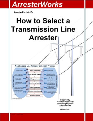
  • 2. ArresterFacts 017a How to Select a Transmission Line Arrester © ArresterWorks 2012 Visit ArresterWorks ArresterFacts Library for other Resources Page2 How to Select a Transmission Line Arrester Introduction Selecting any arrester for an application can be as easy as copying the catalog number from the last inquiry your company submitted or as difficult as running a full blown system lightning/switching surge study. The objective of this ArresterFacts is to help the novice as well as the experienced specifier of transmission line arresters (TLA) by taking you through the necessary steps in TLA selection. Along with outlining the selection steps, it offers rationale and guidance in each step. This is the second ArresterFacts in a series on transmission line arresters. The first in the series is titled “What is a Transmission Line Arrester” and can be found in my ArresterFacts Library on ArresterWorks.com. The third in the series will focus on how to determine where to install transmission line arresters. What is a Line Arrester Before we can define a line arrester, allow me to clarify the name. This power system component has been given several names over the years. Recently in the IEC community the term has been divided into two more distinct terms, NGLA (non-gapped line arrester) and EGLA (externally gapped line arrester). In Cigre and other circles, it is referred to as an LSA (line surge arrester). In the IEEE regions, it is often called a TLA (transmission line arrester) and LA (line arrester or lightning arrester). This process will focus on the NGLA and I will refer to this Figure 1 Transmission Line Arrester Selection Process
  • 3. ArresterFacts 017a How to Select a Transmission Line Arrester © ArresterWorks 2012 Visit ArresterWorks ArresterFacts Library for other Resources Page3 arrester using this acronym. A future ArresterFacts covering the EGLA selection will be published later this year. Even though the NGLA has been in existence for many years, it is still a product that is difficult to obtain information on. If you check the IEC standards you will not find any definition or reference to a NGLA or transmission line arrester. In the IEEE standards the term line arrester is defined as follows: “A line arrester is a type of arrester that is commonly applied to power systems to reduce the risk of insulator flashover during a lightning transient.” I would like to add it may or may not be used to protect the insulator from other types of transients such as switching surges. A line arrester is not generally used to protect any equipment other than line insulators. The NGLA Selection Process The process of selecting an NGLA can be very daunting for the novice and even for the expert in power systems since it is done so seldom. Both IEEE and IEC application guides give versions of how to select a standard arrester however neither one covers the selection of a NGLA arrester. The fundamental process of selecting an arrester for a particular application is to determine the characteristics of the system and location where the arrester will be installed, and then select the arrester characteristics that will meet the requirements of the application. To facilitate the selection of an NGLA, I have configured a clear straightforward 6-step process that considers all issues. Using the process as shown in Figure 1 you can see that for each step in the selection process, the system parameters are determined first and then the corresponding arrester parameters are selected. Step 1 Selecting the Arrester Type The selection process begins with choosing the arrester type that appears to best meet the needs of the application. Even though this is fundamentally one of the most important steps it is routinely left out of procedures in the standards. For example when the objective is to select an arrester for a 33kV sub-transmission line, there is no need to think about Class 5 arresters that would ordinarily be installed on a 400-800kV lines. This initial choice can easily be modified if an issue arises in upcoming steps. The important actions of this step are: 1. Identify the approximate location of the arrester in the system. 2. Review available arresters and their characteristics data. 3. Make the Initial Selection of the Target Arrester Family Another important consideration when selecting an arrester to be installed on a transmission line or sub-transmission line is to consider the housing type. Whenever possible, first priority should be given to the polymer housed type arresters as shown in Figure 7, since they often are lighter and more easily mounted on a transmission line than porcelain housed arresters. Step 2 Selecting the AC Rating Since most arresters are energized with an AC voltage throughout their life, this step is critical and cannot be skipped. An incorrect AC rating could result in premature arrester failure and a system outage. The MCOV or Uc of a TLA is the AC rating of concern. This is the maximum AC voltage that can be applied continuously across the terminals of the arrester. For NGLAs this AC rating must be checked for temporary overvoltage (TOV) withstand capability and may be adjusted higher to meet the TOV requirements. The initially selected AC rating of an NGLA is generally a minimum
  • 4. ArresterFacts 017a How to Select a Transmission Line Arrester © ArresterWorks 2012 Visit ArresterWorks ArresterFacts Library for other Resources Page4 value and in subsequent steps, it may be increased to meet other constraints. Significant considerations in this step are: 2.1 Determine maximum steady state system line-ground voltage. This is defined as the nominal phase to phase voltage divided by 1.73 times the regulation error. For example, on a 760kV transmission system, the nominal system phase to phase voltage is 760kV therefore the line to earth voltage would be 440kV. Since all systems have some regulation error, this too must be taken into consideration. If the regulation error is 10%, then for example, on the above system, the line to ground voltage could be 440x 1.10 = 485kV. The MCOV/Uc of an arrester for this system, at a minimum, should be 485kV before TOV is taken into account. 2.2 Select an arrester MCOV/Uc that is equal or greater than the voltage determined in 2.1: A general IEC practice is to select a Uc that is 1.05 times the highest continuous line to earth voltage. The IEEE practice is that MCOV should be ≥ than the level in step 2.1. Since this arrester is only eliminating insulator flashover, another 10% can be added to this level to reduce the energy the arrester adsorbs during a switching surge if desired. 2.3 Determine the maximum amplitude and duration of potential overvoltages on the system: This is one of the most difficult steps in selecting any arrester. The difficulty arises from the fact that determining the amplitude and duration of temporary overvoltage events is not an easy task. For arrester selection, the overvoltages of interest are ones that occur during an earth fault on the system. During an earth fault on a 3 phase power system, the voltage on the unfaulted phase will rise to levels that can easily damage an arrester if not promptly removed by a breaker operation. The neutral earthing configuration is the determining factor in calculating the amplitude of the overvoltage during this type of fault on the system. Figure 2 Neutral configurations of Importance Figure 2 shows examples of system configurations of importance. For distribution systems, the worst case amplitude can be determined by the earthing configuration but seldom is the duration clearly understood. Due to the lack of data for these applications, the durations are estimated based on the system type. Figure 3 gives an overview of the typical worst case scenarios. Figure 3 Typical TOV Amplitudes and Duration For transmission lines and substations, the amplitude and duration are much better
  • 5. ArresterFacts 017a How to Select a Transmission Line Arrester © ArresterWorks 2012 Visit ArresterWorks ArresterFacts Library for other Resources Page5 understood and the worst case scenario is seldom used. The systems are most often modeled and the potential TOV levels and durations are available from these fault current studies. Use these amplitudes and durations to compare to the arrester TOV withstand curves in the next step as shown in Figure 4. 2.4 Check that the arrester selected in 2.2 can withstand the overvoltages determined in 2.3 using the arrester TOV curve. Once the arrester MCOV/Uc rating is selected, the characteristics of that arrester will then be tested against other constraints in the selection process. If the other constraints require an increase in the Uc or Ur to meet their requirements, then the AC rating in this step will be overridden. Figure 4 Arrester TOV Curve
  • 6. ArresterFacts 017a How to Select a Transmission Line Arrester © ArresterWorks 2012 Visit ArresterWorks ArresterFacts Library for other Resources Page6 Step 3 Check the Margin of Protection The fundamental purpose of a transmission line arrester is to reduce the risk of insulator flashover due to either switching surges and/or lightning surges. The margin of protection is a standard means of evaluating the level of risk of this flashover. If the arrester clamps the voltage at a fraction of the Critical Flashover Voltage (CFO) of an insulator, then the risk of insulator flashover is quite low. Neither the IEC or IEEE standards make a recommendation as to what is adequate margin of protection for line insulators. They do recommend that the arrester residual voltage not be more than 80-85% of insulator BIL in stations. A graphic representation of margin of protection calculations is shown in Figure 5. The fundamental parts to the step in the Margin of Protection selection process are: 3.1 Determine the Insulation Withstand Characteristics 3.1.1 LI CFO (LIWV) 3.1.2 SI CFO (SIWV) 3.2 Determine Arrester Protective Characteristics 3.2.1 Lightning Protective Level (LIPL) 3.2.2 Switching Protective Level (SIPL) 3.3 Determine if there is any Lead Length Effect 3.4 Calculate Margin of Protection 3.4.1 Lightning Protection Margin 3.4.2 Switching Protective Margin Figure 5 Arrester Insulation Coordination Formula
  • 7. ArresterFacts 017a How to Select a Transmission Line Arrester © ArresterWorks 2012 Visit ArresterWorks ArresterFacts Library for other Resources Page7 Step 4 Check Energy Handling Capabilities This is another very important part of the selection procedure of an NGLA. During this consideration, the purpose of the arrester installation must be well understood. Considerations that need to be taken into account in this part of the selection are: System with OHGW If the arrester is to be used on a system that is equipped with an overhead ground wire (OHGW), the energy requirements of the arrester are much lower than if it is not equipped with the OHGW. This is due to the fact that most of the lightning current during a stroke is shunted to ground via the down conductor and only 10-20% of the lightning current flows through the arrester on to the phase. If the footing resistance of the tower is quite high, more current will be diverted through the arrester and into the phase but in the worst case, most will still flow to earth instead of on to the conductor. For configurations less than 300kV system voltage, a distribution class arrester is all that is needed for ample reliability and protection. Using a distribution class arrester for lightning protection where little switching surge energy is available is standard practice in the US and Japan. If a more conservative rating is desired for this configuration, a lower station class arrester can be used, but is not necessary. For systems above 300kV, the class of arrester will likely be higher than a distribution class arrester due to switching surge energy demands. Systems without OHGW If the NGLA application is on a system without an OHGW, the full lightning stroke is likely to pass through the arrester. Since a very low system outage rate is desired, then it is suggested that an Intermediate or Station Class arrester be used to protect this type of system. Distribution arresters are an option of course, but to ensure that the arrester has an extremely low risk of failure due to a high current stroke, it is better to use an Intermediate or Station Arrester. Switching Surge Energy Considerations If the NGLA application is to control surges generated during switching events, the potential switching surge energy of the system needs to be calculated and compared to the energy handling capabilities of the arrester. For distribution systems and transmission systems below 230kV, the potential switching surge energy of the system does not exceed that of a Distribution class arrester. Therefore, when considering switching surge control on these systems, there is no need to consider higher energy ratings. For systems above 230kV, a precise energy dissipation requirement can be determined using transient analysis software or an estimate can be made using simple formulas found in either IEC 60099-5 or IEEE C62.22. IEC 60071-2 offers an excellent estimation of what magnitude of switching surges to expect on power systems from normal energization operations. According to this standard, switching surges can range from 1.2pu to 3.5pu depending on the system and action during the event. This translates into energies between 4-10kJ/kV MCOV/Uc which is well within the range of most station arrester designs. IEC Lightning Impulse Discharge Capability Test For arresters applied to systems up to 52kV, the High Current Impulse capability is the only means of classifying the lightning impulse capability. For all distribution-10kA arresters, the designs must be capable of withstanding 100kA 2x10uS impulse at least 2 times. For 5kA arresters, this high current capability is reduced to 65kA. For arresters applied to systems 52kV and above, a special test requirement and withstand capability is available to the specifier of arresters. Since 2006, all line surge arresters applied to systems above 52kV are required to be tested per the
  • 8. ArresterFacts 017a How to Select a Transmission Line Arrester © ArresterWorks 2012 Visit ArresterWorks ArresterFacts Library for other Resources Page8 Lightning Impulse Discharge Capability test outlined in IEC 60099-4 Annex N. This new lightning impulse capability test uniquely tests the arrester with an impulse that crests in 200uS and is sinusoidal in shape. This test is unique because the arrester does not pass or fail, they just fall into one of many available categories of withstand. A further unique feature of this test is that the arrester withstand can be measured in either energy (joules) or in Charge (A-Seconds). A Distribution type arrester can have ratings as high as .5 coulombs and a Station Class arrester approximately equal to 3.6 coulombs of charge transfer. When selecting an arrester for line protection above 52kV, this characteristic should be considered. Step 5 Check Failure Modes This is another important arrester selection steps for an NGLA if the arrester is located near highways or occupied buildings. If the arrester is overloaded, it often becomes a short circuit to the system to which it is applied. If this happens, the power system will supply all potential fault current to the circuit including the arrester. If a shorted arrester experiences more power-frequency fault current than it was designed to handle, it could eject very hot components at significant distance and velocity. A fragmenting overload is a highly undesirable event. To insure that this type of overload event does not occur, the short circuit current withstand capability of the NGLA needs to be higher than the available fault current of the system. The short circuit rating of all arresters is found on the nameplate of the arrester and in the manufacturing literature. Typically distribution systems can supply only 10kA fault current, occasionally higher. Therefore the NGLA for distribution systems needs to be 10-15kA maximum. For transmission lines above 50kV, the available fault current can be as high as 65kA with grounded systems, and low as a Figure 6 Acceptable Failure Mode Figure 7 Undesirable Failure Mode
  • 9. ArresterFacts 017a How to Select a Transmission Line Arrester © ArresterWorks 2012 Visit ArresterWorks ArresterFacts Library for other Resources Page9 few hundred amps for impedance grounded or floating delta systems. When an arrester has been subjected to an overload, it should look similar to Figure 6 when the event is over. However if the system ground fault current exceeds the rating of the arrester what is seen in Figure 7 may occur which is highly undesirable. The user needs to know the available fault current on the system to which the arrester is to be mounted. This data is readily available from the relay or system analysis personnel. Step 6 Mounting Considerations Line surge arresters are stressed physically more than any other arrester. This is because they are mounted on or near towers that are very exposed to the elements. Vibration, wind, torque, impact stress and animal abuse are the main reasons for the high stresses. For these afore mentioned reasons the selection of mounting components is very important and often times the most difficult part of NGLA selection. Also since there are so many tower configurations the mounting requirement for each installation is unique. The following are specific and important mounting features to consider. Vibration: Presently there are no standard tests to determine if an NGLA can withstand vibrations found at tower tops and on conductors. It is advised that the user discuss this with suppliers. Disconnector Strength: If the NGLA is equipped with a disconnector it is imperative that the mounting does not stress this component beyond its capability. If the arrester is to be mounted with the disconnector in any way other than the weight of the ground lead, then this should be discussed with the supplier. Some disconnectors are designed for this type of stress, but not all of them. Lead Swing: This is one of the biggest reasons for NGLA issues since a swinging lead not only can break itself, but it can also transfer the mechanical stresses to the other components. Again there is no standard for this issue so it must be discussed with the supplier. One solution that is often used is to string the lead through a chain that reduces the frequency and amplitude of the swing as well as reduces the direct strain on the lead. Figure 7 shows this arrangement. Bird Droppings: Just like an insulator, if the NGLA is to be mounted where it is subject to bird droppings, use the same precautions you would if it was an insulator. BIL Restoration: If the NGLA had been overloaded and failed, it should be mounted so that it will disconnect allowing full system BIL to be restored. This is accomplished by mounting the arrester so that it or its lead will swing out of the way if it becomes a short circuit. Figure 7 Lead Reinforcement with a chain PhotoComplimentsofHubbellPowerSystems
  • 10. ArresterFacts 017a How to Select a Transmission Line Arrester © ArresterWorks 2012 Visit ArresterWorks ArresterFacts Library for other Resources Page10 Summary Once you have completed all 6 steps of the NGLA selection process, you will likely have the optimum arrester chosen for the application. There may be times that this process will need to be completed several times before the final arrester is chosen. When the arresters are installed, you will be pleased with the results. NGLAs are major reliability enhancers for power systems. ************** ____________________________________________________________________________________ ArresterFacts Usage ArresterFacts are Copyrighted documents intended for the education of arrester users and stakeholders. If you choose to copy any part of this document for teaching purposes you have my permission, however please give ArresterWorks proper credit. Thank you for using www.ArresterWorks.com as a source of information on high voltage surge arresters. Jonathan Woodworth Principal Consultant ArresterWorks