지브라스캐너 Zebra CS3000 1D 포켓타입 모바일스캐너 매뉴얼

사용자의 편안함과 사용 편이성을 보장해 주는 지브라의 인체공학적 캡처 기능 사용이 간편한 모바일스캐너 CS3000 시리즈는 매우 직관적이고 단수한 2개의 버튼이 별도의 교육이 없어도 손쉽게 사용할 수 있습니다. 그 외에도, 손과 손가락이 가장 편안한 스캔 위치로 인도되도록 홈이 파여 있고 트리거 버튼이 연질 고무 재질로 만들어져 있어 대부분의 스캔 집약적 작업을 편안하게 처리할 수 있습니다. 동급 최고의 고성능 스캔 이 제품은 세계적으로 유명한 스캔 품질 및 신뢰성을 제공하는 지브라의 SE955 스캔 엔진을 내장하고 있습니다. 또한 광범위한 작동 범위가 지원되므로 어떠한 조명 조건 하에서든 접촉 지점에서부터 114.3cm/45in. 까지의 거리에서 바코드를 캡처할 수 있을 만큼 탁월한 애플리케이션 유연성이 보장됩니다. 아울러 손상되었거나 품질이 불량한 바코드까지도 캡처할 수 있을 정도로 성능이 뛰어날뿐 아니라 각 일괄 처리 스캔 작업마다 시간 스탬프를 자동적으로 첨부할 수 있는 비즈니스 인텔리전스 기능이 추가로 제공됩니다. 두 가지의 유연한 작동 모드 (일괄처리 및 실시간)를 이용해 작업순서를 자동화 일괄 처리 모드에서 이 포켓형 장치는 보안 요원과 경비 직원이 출입문 및 기타 장소의 바코드를 스캔하고 교대 시간 종료 시 시간 및 날짜 스탬프 데이터를 업로드하여 정확한 활동 종료 사실을 문서화할 수 있는 기능을 제공합니다. 또한 지브라 CS3000 시리즈는 제조업체 및 대리점이 고객에게 CS3000을 지급하고 사용 시점에 재고를 스캔하도록 함으로써 소비 현장과 연동하여 주문 프로세스를 효과적으로 자동화하는 등 기업 외부에서도 널리 활용됩니다. 유연한 모바일 1D 레이저 스캐너 두 가지 작동 모드를 지원하는 모바일 바코드 스캐너: 데이터를 호스트에 일괄 처리 방식으로 업로드하거나 스마트폰, PDA 및 랩탑에 대한 무선 블루투스 연결을 통해 호스트 애플리케이션으로 실시간 캡처 및 전송 긴 배터리 사용 시간 아울러 24시간 일괄 처리/12 시간 블루투스 모드 배터리 수명이 지원되므로 한 번 충전으로 일과 시간 내내 충분히 스캔 작업을 수행할 수 있습니다. 심플한 투 버튼 디자인 편안하고 손쉬운 사용: 거의 교육 없이 작동 가능 작고 가벼운 중량 포켓 또는 목 거치대에 딱 들어 맞는 작은 크기와 70g에 불과한 무게 호스트 장치와 손쉽게 통합 일괄 처리 USB 연결 또는 무선 블루투스 기능을 통해 거의 모든 호스트 장치와의 호환성을 지원 512MB 비휘발성 메모리 백만 건이 넘는 스캔 데이터를 저장할 수 있는 용량 및 확실한 데이터 보존성: 거의 모든 일괄 처리 작업에 매우 적합 탁월한 스캐닝 성능 손쉽고 직관적인 사용 가리키고 클릭하는 것만으로 스캔이 완료되며, 더럽거나 손상되었거나 품질이 불량한 바코드까지 손쉽게 캡처 기업용 수준의 내구성 1.2m/4ft. 낙하 사양, 0.5m/1.64ft 높이에서 250회 낙하(500회의 충격), IP40 봉합 떨어뜨리거나 부딪힐 수밖에 없는 실제 사용 환경에서 안정적인 작동을 보장 PHYSICAL SPECIFICATIONS Dimensions : 3.41 in. L x 1.95 in. W x 0.87 in H 8.65 cm L x 4.95 cm W x 2.2 cm H Weight (With batteries) : 2.45 ozs./70 gms PERFORMANCE CHARACTERISTICS Decode capability : 1-D Interfaces supported : USB, USB 2.0 Host Scan pattern : Single line Memory : 512 MB Flash USER ENVIRONMENT Ambient lighting tolerance : Tolerant to typical artificial indoor and natural outdoor (direct sunlight) lighting conditions. Fluorescent, Incandescent, Mercury Vapor, Sodium Vapor, LED : 450 Ft Candles (4, 844 Lux) Sunlight: 8000 Ft Candles (86, 111 Lux) Operating temperature : 32° to 104° F /0° to 40° C Drop specifications : 4 ft./1.21 m drop to tiled linoleum over concrete, 6 drops per 6 sides, across the operating temperature range Storage temperature : -40° to 158° F /-40° to 70°C REGULATOR Laser/LED safety : EN 60825-1, IEC 60825-1, 21CFR1040.10 Radio : EN 300 328 Environmental : RoHS Directive 2002/95/EEC EMI/RFI : EN 301 489-1, EN 301 489-17, EN 55022, FCC Part 15 Class B, ICES 003 Class B, EN 55024 Electrical safety : UL 60950-1, C22.2 No. 60950-1, EN 60950-1, IEC 60950-1 >하이온아이티 주소 : 서울 금천구 가산디지털2로 165, 1304호 (백상스타타워2차) 대표번호 : 02-2038-0018 / 이메일 : hion@hionit.com 홈페이지 : http://hionsmart.com/

Recommended
Recommended
More Related Content
What's hot
What's hot (12)
Similar to 지브라스캐너 Zebra CS3000 1D 포켓타입 모바일스캐너 매뉴얼
Similar to 지브라스캐너 Zebra CS3000 1D 포켓타입 모바일스캐너 매뉴얼 (20)
More from HION IT
More from HION IT (20)
Recently uploaded
Recently uploaded (20)
지브라스캐너 Zebra CS3000 1D 포켓타입 모바일스캐너 매뉴얼
- 3. CS3000 SERIES SCANNER PRODUCT REFERENCE GUIDE 72E-136088-05 Revision A March 2015
- 4. ii CS3000 Series Scanner Product Reference Guide © 2015 Symbol Technologies, Inc. No part of this publication may be reproduced or used in any form, or by any electrical or mechanical means, without permission in writing from Zebra. This includes electronic or mechanical means, such as photocopying, recording, or information storage and retrieval systems. The material in this manual is subject to change without notice. The software is provided strictly on an “as is” basis. All software, including firmware, furnished to the user is on a licensed basis. Zebra grants to the user a non-transferable and non-exclusive license to use each software or firmware program delivered hereunder (licensed program). Except as noted below, such license may not be assigned, sublicensed, or otherwise transferred by the user without prior written consent of Zebra. No right to copy a licensed program in whole or in part is granted, except as permitted under copyright law. The user shall not modify, merge, or incorporate any form or portion of a licensed program with other program material, create a derivative work from a licensed program, or use a licensed program in a network without written permission from Zebra. The user agrees to maintain Zebra’s copyright notice on the licensed programs delivered hereunder, and to include the same on any authorized copies it makes, in whole or in part. The user agrees not to decompile, disassemble, decode, or reverse engineer any licensed program delivered to the user or any portion thereof. Zebra reserves the right to make changes to any software or product to improve reliability, function, or design. Zebra does not assume any product liability arising out of, or in connection with, the application or use of any product, circuit, or application described herein. No license is granted, either expressly or by implication, estoppel, or otherwise under any Zebra Technologies Corporation, intellectual property rights. An implied license only exists for equipment, circuits, and subsystems contained in Zebra products. Zebra and the Zebra head graphic are registered trademarks of ZIH Corp. The Symbol logo is a registered trademark of Symbol Technologies, Inc., a Zebra Technologies company. Zebra Technologies Corporation Lincolnshire, IL U.S.A. http://www.zebra.com Warranty For the complete Zebra hardware product warranty statement, go to: http://www.zebra.com/warranty.
- 5. iii Revision History Changes to the original manual are listed below: Change Date Description -01 Rev A 07/2010 Initial release -02 Rev A 10/2010 Added Motorola Droid Bluetooth connection example. -03 Rev A 2/2012 Replaced specifications with link to specification/data sheet, added battery replacement note, add information for connecting to an iPad. -04 Rev A 2/2013 Updated out of range behavior description. -05 Rev A 12/2014 Zebra Rebranding
- 6. iv CS3000 Series Scanner Product Reference Guide
- 7. TABLE OF CONTENTS About This Guide Introduction ..................................................................................................................................... xi Product Reference Guide – Start Here ..................................................................................... xi Chapter Descriptions ...................................................................................................................... xi Notational Conventions................................................................................................................... xii Related Documents ........................................................................................................................ xiii Service Information......................................................................................................................... xiii Chapter 1: Getting Started Introduction .................................................................................................................................... 1-1 Unpacking the Scanner .................................................................................................................. 1-2 The Cradle ..................................................................................................................................... 1-2 Connecting the Cradle ............................................................................................................. 1-2 Charging the Scanner Battery ........................................................................................................ 1-3 Charging via USB Host Cable .................................................................................................. 1-3 Charging via Charging Cradle .................................................................................................. 1-4 Scanner Charging LED ............................................................................................................ 1-5 Connecting to the Host Computer .................................................................................................. 1-5 Batch Connection ..................................................................................................................... 1-5 Bluetooth Connection: Development Options .......................................................................... 1-5 Bluetooth Connection Examples .............................................................................................. 1-6 Numeric Bar Codes for PIN Entry .................................................................................................. 1-24 Configuring the Scanner ................................................................................................................ 1-25 Staging Multiple Scanners ....................................................................................................... 1-25 Editing the Configuration File ................................................................................................... 1-26
- 8. vi CS3000 Series Scanner Product Reference Guide Chapter 2: Scanning Introduction .................................................................................................................................... 2-1 Scanning ........................................................................................................................................ 2-1 Deleting Bar Codes .................................................................................................................. 2-2 Transmitting Bar Code Data to Host .............................................................................................. 2-2 Transferring Data from a Batch Scanner ................................................................................. 2-2 Transferring Data from an RF Scanner .................................................................................... 2-2 User Interface Definitions .............................................................................................................. 2-3 LED Indications ........................................................................................................................ 2-3 Beeper Indications ................................................................................................................... 2-5 Chapter 3: User Preferences Introduction .................................................................................................................................... 3-1 Scanning Sequence Examples ...................................................................................................... 3-1 Errors While Scanning ................................................................................................................... 3-1 User Preferences Default Parameters ........................................................................................... 3-2 Reset ............................................................................................................................................. 3-4 Reset Factory Defaults .................................................................................................................. 3-4 Set Date and Time ......................................................................................................................... 3-5 Set Date ................................................................................................................................... 3-5 Set Time ................................................................................................................................... 3-5 Cancel Date and Time Setting ................................................................................................. 3-5 Numeric Bar Codes for Date and Time Settings ...................................................................... 3-6 Clear Data ...................................................................................................................................... 3-7 Beeper Settings ............................................................................................................................. 3-8 Beeper Volume ........................................................................................................................ 3-8 Beeper Tone ............................................................................................................................ 3-9 Mute Beeper ............................................................................................................................ 3-10 Scanner Options ............................................................................................................................ 3-11 Scan Angle ............................................................................................................................... 3-11 Transmit “No Read” Message .................................................................................................. 3-12 Bluetooth Options .......................................................................................................................... 3-13 Bluetooth Unpair ...................................................................................................................... 3-13 Bluetooth HID Profile ............................................................................................................... 3-13 Bluetooth Serial Port Profile (SPP) .......................................................................................... 3-13 Disable All Symbologies ................................................................................................................ 3-14 Linear Code Type Security Level ................................................................................................... 3-15 Bi-directional Redundancy ............................................................................................................. 3-16 Data Options .................................................................................................................................. 3-17 Transmit Code ID Character .................................................................................................... 3-17 Prefix/Suffix Values .................................................................................................................. 3-18 Scan Data Transmission Format ............................................................................................. 3-19 Send Versions ............................................................................................................................... 3-21 Firmware Version ..................................................................................................................... 3-21 Bluetooth Version ..................................................................................................................... 3-21 Scan Engine Version ............................................................................................................... 3-21 Save Configuration ........................................................................................................................ 3-22
- 9. Table of Contents vii Chapter 4: Symbologies Introduction .................................................................................................................................... 4-1 Scanning Sequence Examples ...................................................................................................... 4-1 Errors While Scanning ................................................................................................................... 4-1 Symbology Default Parameters ..................................................................................................... 4-2 UPC/EAN ....................................................................................................................................... 4-5 Enable/Disable UPC-A ............................................................................................................. 4-5 Enable/Disable UPC-E ............................................................................................................. 4-5 Enable/Disable UPC-E1 ........................................................................................................... 4-6 Enable/Disable EAN-8 ............................................................................................................. 4-6 Enable/Disable EAN-13 ........................................................................................................... 4-7 Enable/Disable Bookland EAN ................................................................................................ 4-7 Decode UPC/EAN Supplementals ........................................................................................... 4-8 User-Programmable Supplementals ........................................................................................ 4-12 Decode UPC/EAN Supplemental Redundancy ....................................................................... 4-12 Transmit UPC-A Check Digit ................................................................................................... 4-13 Transmit UPC-E Check Digit ................................................................................................... 4-13 Transmit UPC-E1 Check Digit ................................................................................................. 4-14 UPC-A Preamble ..................................................................................................................... 4-14 UPC-E Preamble ..................................................................................................................... 4-15 UPC-E1 Preamble ................................................................................................................... 4-16 Convert UPC-E to UPC-A ........................................................................................................ 4-17 Convert UPC-E1 to UPC-A ...................................................................................................... 4-17 EAN Zero Extend ..................................................................................................................... 4-18 Bookland ISBN Format ............................................................................................................ 4-19 UPC/EAN Security Level ......................................................................................................... 4-20 UCC Coupon Extended Code .................................................................................................. 4-21 Code 128 ....................................................................................................................................... 4-21 Enable/Disable Code 128 ........................................................................................................ 4-21 Enable/Disable GS1-128 (formerly UCC/EAN-128) ................................................................. 4-22 Enable/Disable ISBT 128 ......................................................................................................... 4-22 Lengths for Code 128 .............................................................................................................. 4-22 Code 39 ......................................................................................................................................... 4-23 Enable/Disable Code 39 .......................................................................................................... 4-23 Enable/Disable Trioptic Code 39 ............................................................................................. 4-23 Convert Code 39 to Code 32 (Italian Pharma Code) ............................................................... 4-24 Code 32 Prefix ......................................................................................................................... 4-24 Set Lengths for Code 39 .......................................................................................................... 4-25 Code 39 Check Digit Verification ............................................................................................. 4-26 Transmit Code 39 Check Digit ................................................................................................. 4-26 Enable/Disable Code 39 Full ASCII ......................................................................................... 4-27 Code 93 ......................................................................................................................................... 4-28 Enable/Disable Code 93 .......................................................................................................... 4-28 Set Lengths for Code 93 .......................................................................................................... 4-28 Code 11 ......................................................................................................................................... 4-30 Enable/Disable Code 11 .......................................................................................................... 4-30 Set Lengths for Code 11 .......................................................................................................... 4-30 Code 11 Check Digit Verification ............................................................................................. 4-32 Transmit Code 11 Check Digits ............................................................................................... 4-33 Interleaved 2 of 5 ........................................................................................................................... 4-33 Enable/Disable Interleaved 2 of 5 ............................................................................................ 4-33
- 10. viii CS3000 Series Scanner Product Reference Guide Set Lengths for Interleaved 2 of 5 ............................................................................................ 4-34 I 2 of 5 Check Digit Verification ................................................................................................ 4-36 Transmit I 2 of 5 Check Digit .................................................................................................... 4-36 Convert I 2 of 5 to EAN-13 ....................................................................................................... 4-37 Discrete 2 of 5 ................................................................................................................................ 4-37 Enable/Disable Discrete 2 of 5 ................................................................................................. 4-37 Set Lengths for Discrete 2 of 5 ................................................................................................ 4-38 Chinese 2 of 5 ................................................................................................................................ 4-39 Enable/Disable Chinese 2 of 5 ................................................................................................. 4-39 Codabar ......................................................................................................................................... 4-39 Enable/Disable Codabar .......................................................................................................... 4-39 Set Lengths for Codabar .......................................................................................................... 4-40 CLSI Editing ............................................................................................................................. 4-41 NOTIS Editing .......................................................................................................................... 4-41 MSI ................................................................................................................................................ 4-42 Enable/Disable MSI ................................................................................................................. 4-42 Set Lengths for MSI ................................................................................................................. 4-43 MSI Check Digits ..................................................................................................................... 4-44 Transmit MSI Check Digit ........................................................................................................ 4-44 MSI Check Digit Algorithm ....................................................................................................... 4-45 GS1 DataBar ................................................................................................................................. 4-45 Enable/Disable GS1 DataBar-14 ............................................................................................. 4-45 Enable/Disable GS1 DataBar Limited ...................................................................................... 4-46 Enable/Disable GS1 DataBar Expanded ................................................................................. 4-46 Convert GS1 DataBar to UPC/EAN ......................................................................................... 4-47 Numeric Bar Codes ....................................................................................................................... 4-48 Cancel ............................................................................................................................................ 4-50 Chapter 5: Maintenance and Technical Specifications Introduction .................................................................................................................................... 5-1 Maintenance .................................................................................................................................. 5-1 Troubleshooting ............................................................................................................................. 5-2 Technical Specifications ................................................................................................................ 5-3 Decode Zone ................................................................................................................................. 5-3 Appendix A: Standard Default Parameters Appendix B: Programming Reference Code Type IDs ............................................................................................................................... B-1 Symbol Code Identifiers ................................................................................................................. B-2 AIM Code Identifiers ...................................................................................................................... B-3 GS1-128 (formerly UCC/EAN-128) ................................................................................................ B-6 Setting Prefixes and Suffixes ......................................................................................................... B-7
- 11. Table of Contents ix Appendix C: Sample Bar Codes UPC-A ............................................................................................................................................ C-1 UPC-E ............................................................................................................................................ C-1 UPC-E1 .......................................................................................................................................... C-2 EAN-13 .......................................................................................................................................... C-2 EAN-8 ............................................................................................................................................ C-2 Code 39 ......................................................................................................................................... C-2 Trioptic Code 39 ............................................................................................................................. C-3 Code 93 ......................................................................................................................................... C-3 Code 11 ......................................................................................................................................... C-3 Codabar ......................................................................................................................................... C-4 MSI ................................................................................................................................................. C-4 Interleaved 2 of 5 ........................................................................................................................... C-4 Index
- 12. x CS3000 Series Scanner Product Reference Guide
- 13. ABOUT THIS GUIDE Introduction The CS3000 Series Scanner Product Reference Guide provides general instructions for setting up, operating, maintaining, and troubleshooting the scanner. The CS3000 series scanner is available in the following configurations: • CS3000 - USB (batch), 0.5 GB Flash • CS3070 - USB (batch) and Bluetooth, 0.5 GB Flash Each scanner includes a USB host cable. A charging cradle is also available for mounting, charging, and host connection. Product Reference Guide – Start Here Go to the last page of this electronic manual and print it out. This is the Quick Start Instructions. This single page provides links within the document to technical support for 99% of all customer questions. Chapter Descriptions Topics covered in this guide are as follows: • Chapter 1, Getting Started provides a product overview and describes how to charge, connect, and configure the scanner. • Chapter 2, Scanning provides instructions for how to scan bar codes and send the data to a host, as well as beeper and LED definitions. • Chapter 3, User Preferences describes each user preference feature and provides the programming bar codes for selecting these features for the scanner. It also includes wireless communication parameters and commonly used bar codes to customize how data is transmitted to the host device. • Chapter 4, Symbologies describes all symbology features and provides the programming bar codes for selecting these features. • Chapter 5, Maintenance and Technical Specifications provides information on how to care for the scanner, troubleshooting, and technical specifications.
- 14. xii CS3000 Series Scanner Product Reference Guide • Appendix A, Standard Default Parameters provides a table of all host devices and miscellaneous scanner defaults. • Appendix B, Programming Reference provides a table of AIM code identifiers, ASCII character conversions, and keyboard maps. • Appendix C, Sample Bar Codes includes sample bar codes. Notational Conventions The following conventions are used in this document: • Italics are used to highlight the following: • Chapters and sections in this and related documents • Bold text is used to highlight the following: • Key names on a keypad • Button names on a screen or window. • bullets (•) indicate: • Action items • Lists of alternatives • Lists of required steps that are not necessarily sequential • Sequential lists (e.g., those that describe step-by-step procedures) appear as numbered lists. • Throughout the programming bar code menus, asterisks (*) are used to denote default parameter settings. *Baud Rate 9600 Feature/Option* Indicates Default NOTE This symbol indicates something of special interest or importance to the reader. Failure to read the note will not result in physical harm to the reader, equipment or data. CAUTION This symbol indicates that if this information is ignored, the possiblity of data or material damage may occur. WARNING! This symbol indicates that if this information is ignored the possibility that serious personal injury may occur.
- 15. About This Guide xiii Related Documents • CS3000 Series Scanner Quick Reference Guide (p/n 72-136598-xx) provides general information to help the user get started with the scanner, including basic setup and operation instructions. For the latest version of this guide and all guides, go to: http://www.zebra.com/support. Service Information If you have a problem using the equipment, contact your facility's technical or systems support. If there is a problem with the equipment, they will contact the Zebra Global Customer Support Center at: http://www.zebra.com/support. When contacting Zebra support, please have the following information available: • Serial number of the unit • Model number or product name • Software type and version number Zebra responds to calls by e-mail, telephone or fax within the time limits set forth in service agreements. If your problem cannot be solved by Zebra support, you may need to return your equipment for servicing and will be given specific directions. Zebra is not responsible for any damages incurred during shipment if the approved shipping container is not used. Shipping the units improperly can possibly void the warranty. If you purchased your business product from a Zebra business partner, please contact that business partner for support.
- 16. xiv CS3000 Series Scanner Product Reference Guide
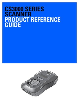
- 17. CHAPTER 1 GETTING STARTED Introduction The CS3000 Series Scanner captures and stores bar codes for a variety of uses, and transmits bar code data to a host via USB connection or Bluetooth. Figure 1-1 CS3000 Series Scanner This scanner supports the following host interfaces: • USB - The scanner connects to a USB host as a removable storage device, via a cradle or USB cable. • Bluetooth - The scanner supports Bluetooth HID connection to a host (the default) where the scanner emulates a keyboard, as well as Serial Port Profile (SPP) connection where the scanner behaves as if there is a serial connection. Mini-USB Port Scan Button LED Bluetooth Button/LED Delete Button Protective Cover Reset Button
- 18. 1 - 2 CS3000 Series Scanner Product Reference Guide Unpacking the Scanner Remove the scanner from its packing and inspect it for damage. If the scanner was damaged in transit, contact Zebra support. See page xiii for contact information. KEEP THE PACKING. It is the approved shipping container and should be used if the equipment ever needs to be returned for servicing. The Cradle The cradle sits on a desktop and serves as a stand, charger, and USB communication device for the CS3000 series scanner. The cradle does not require a separate power supply to charge the scanner. Figure 1-2 Cradle Connecting the Cradle Insert the cradle’s interface cable into a USB port on the host. Figure 1-3 Connecting the Cables to the Cradle
- 19. Getting Started 1 - 3 Charging the Scanner Battery To charge the CS3000 series scanner, connect it to a host PC via the USB host cable or charging cradle. No power supply is necessary. Charge time is approximately three hours for a fully discharged battery. Charging via USB Host Cable 1. Insert the mini-USB connector on the host cable in the interface port on the scanner. 2. Connect the other end of the host cable to a USB port on the host PC. Figure 1-4 Connecting Scanner to Host PC The scanner begins charging. A complete charge of a fully discharged battery takes approximately three hours. Charge within the recommended temperature of 32° to 104° F (0° to 40° C). NOTE To check the battery charge status, hold the scan (+) button for 15 seconds. See Battery charge status in Table 2-1 on page 2-3. NOTE An authorized Zebra repair facility can replace the CS3000 battery. Changing the battery does not affect bar code data which is stored in non-volatile memory, however the date and time is lost upon changing the battery or if the battery completely loses charge.
- 20. 1 - 4 CS3000 Series Scanner Product Reference Guide Charging via Charging Cradle 1. Insert the cradle’s USB connector into a USB port on the host PC. Figure 1-5 Connecting Cradle to Host PC 2. Remove the protective cover from the scanner. 3. Place the scanner in the cradle, ensuring the mini-USB connector in the cradle inserts into the interface port on the scanner. Figure 1-6 Inserting Scanner in Cradle The scanner begins charging. A complete charge of a fully discharged battery takes approximately three hours. Charge within the recommended temperature of 32° to 104° F (0° to 40° C).
- 21. Getting Started 1 - 5 Scanner Charging LED The scanner’s LED indicates charging activity (see Table 2-1 on page 2-3). The amber LED blinks slowly during charging. The scanner’s LED turns solid green when the battery is fully charged. Connecting to the Host Computer Batch Connection See Charging the Scanner Battery on page 1-3 for instructions on connecting the scanner to a host PC via USB. Bluetooth Connection: Development Options Serial Port Profile This Bluetooth profile emulates a serial cable to provide a simply implemented wireless replacement for existing RS-232 based serial communications applications, including familiar control signals. It is the preferred communication profile implementation because accidental key strokes from the keyboard or touch screen on the host are not entered into the bar code data stream. Human Interface Device Emulation This Bluetooth profile is a lightweight wrapper of the Human Interface Device protocol defined for USB. Data transmitted from the Bluetooth scanner appears as keyboard entries to the Bluetooth host (Smartphone, PC, etc). NOTE To enter batch scanning mode, the scanner cannot be paired to a Bluetooth host (applies to CS3070 model only). NOTE Wedge data appears within whichever application has input focus.
- 22. 1 - 6 CS3000 Series Scanner Product Reference Guide Bluetooth Connection Examples This section provides the following connection examples: • Droid X HID pairing Example • PC HID Pairing Example on page 1-7 • PC SPP Pairing Example on page 1-10 • Windows Mobile Device (ES400) HID Pairing Example on page 1-13 • Windows Mobile Device (ES400) SPP Pairing Example on page 1-17 • iPad Pairing Example on page 1-21 Overview Pairing the CS3070 with a host device typically requires entering a pairing PIN on both the CS3070 and the host device. To enter the PIN on the CS3070, use the Numeric Bar Codes for PIN Entry on page 1-24. For the host device, use the data entry method required for that device to enter the PIN. Droid X HID Pairing Example For CS3070 scanners, to pair to a Droid X via HID: 1. Press the scan button (+) to wake the scanner. 2. Press and hold the Bluetooth button (round button with logo) for five seconds. The scanner beeps and the Bluetooth button starts blinking quickly to indicate that the scanner is discoverable by the host. 3. On the Droid X, press the Settings button (bottom left hard button). 4. Tap Settings from the list of options that appears. 5. Tap Wireless & networks. 6. Tap Bluetooth to enable Bluetooth. 7. Tap the Bluetooth settings option. 8. Tap Scan for devices. The CS3070 appears in the Bluetooth devices list, indicated by its model name and serial number. 9. Select the CS3070 from the list. A window prompts for the PIN. 10. Tap the text box to open the soft keyboard. Enter the PIN using the keyboard and tap Ok. 11. With the CS3070, scan the PIN using the Numeric Bar Codes for PIN Entry on page 1-24 and scan Enter. The scanner beeps to indicate it has paired with the Droid, and the Droid displays Connected to hid below the CS3070 device name. To display scanned data on the Droid: 1. Tap and hold the screen to display the Add to Home screen menu. 2. Select widgets. 3. Scroll down the menu and select Sticky Note. NOTE HID is the default profile for the CS3070. If this was changed, scan Bluetooth HID Profile on page 3-13.
- 23. Getting Started 1 - 7 4. Tap Sticky Note to display the text entry screen. 5. Tap in the text entry field and scan a bar code. The bar code contents appear in the text entry field. PC HID Pairing Example For CS3070 scanners, to pair to a Bluetooth-enabled PC or laptop via HID: 1. Press the scan button (+) to wake the scanner. 2. Press and hold the Bluetooth button (round button with logo) for five seconds. The scanner beeps and the Bluetooth button starts blinking quickly to indicate that the scanner is discoverable by the host. 3. On the host PC, launch the third party Bluetooth pairing application. Following is a sample window of such an application. Figure 1-7 Sample Bluetooth Application Window NOTE If the host does not support Bluetooth communication, a third-party Bluetooth adapter is required. NOTE HID is the default profile for the CS3070. If this was changed, scan Bluetooth HID Profile on page 3-13.
- 24. 1 - 8 CS3000 Series Scanner Product Reference Guide 4. Place the application into discover Bluetooth device mode (in this example, select the check box), and click Next. Figure 1-8 Sample Device Discovery Window 5. Select the CS3070 device from the discovered device list. The Bluetooth application may prompt you to scan a passkey it generated, or for you to create and then scan a passkey (PIN). Figure 1-9 Sample Passkey Option Window
- 25. Getting Started 1 - 9 6. Select an option, then click Next: • If you select Choose a passkey for me, the host generates and displays a passkey. • If you select Use the passkey found in the documentation, enter the default 1234. • If you select Let me choose my own passkey, enter any passkey. 7. Scan Numeric Bar Codes for PIN Entry on page 1-24 corresponding to the passkey, then scan the Enter bar code. Figure 1-10 Sample Bluetooth Pairing Completion Window
- 26. 1 - 10 CS3000 Series Scanner Product Reference Guide 8. Click Finish to complete the pairing. The device appears in the Bluetooth Devices window. Figure 1-11 Bluetooth Devices Window 9. Select the device, then click Add... The CS3070 issues a two-tone beep and the Bluetooth button blinks slowly to indicate that the scanner paired with the host. PC SPP Pairing Example For CS3070 scanners, to pair to a Bluetooth-enabled PC or laptop via SPP: 1. Press the scan button (+) to wake the scanner. 2. Scan Bluetooth Serial Port Profile (SPP) on page 3-13. The Bluetooth button starts blinking quickly to indicate that the scanner is discoverable by the host. NOTE Bluetooth pairing suspends temporarily while charging via a USB cable. Disconnecting the cable automatically re-establishes the Bluetooth pairing. NOTE If the host does not support Bluetooth communication, a third-party Bluetooth adapter is required.
- 27. Getting Started 1 - 11 3. On the host PC, launch the third party Bluetooth pairing application. Following is a sample window of such an application. Figure 1-12 Sample Bluetooth Application Window 4. Place the application into discover Bluetooth device mode (in this example, select the check box), and click Next. Figure 1-13 Sample Device Discovery Window
- 28. 1 - 12 CS3000 Series Scanner Product Reference Guide 5. Select the CS3070 device from the discovered device list. The Bluetooth application may prompt you to scan a passkey it generated, or for you to create and then scan a passkey (PIN). Figure 1-14 Sample Passkey Option Window 6. For SPP, select Use the passkey found in the documentation, then enter the default passkey 1234 in the text box. Click Next. Figure 1-15 Sample Bluetooth Pairing Completion Window NOTE For SPP, the host requires entering a PIN, but no PIN entry is required for the CS3070.
- 29. Getting Started 1 - 13 7. Click Finish. In order to complete the pairing, open a serial input application such as HyperTerminal. The CS3070 issues a two-tone beep and the Bluetooth button blinks slowly to indicate that the scanner paired with the host. Windows Mobile Device (ES400) HID Pairing Example To pair to a ES400 Windows Mobile 6.5 device via HID: 1. Press the scan button (+) to wake the scanner. 2. Press and hold the Bluetooth button (round button with logo) for five seconds. The scanner beeps and the Bluetooth button starts blinking quickly to indicate that the scanner is discoverable by the ES400. 3. On the ES400, launch the third party Bluetooth pairing application. Following is a sample window of such an application. Figure 1-16 Sample Bluetooth Application - Add Device Window NOTE Bluetooth pairing suspends temporarily while charging via a USB cable. Disconnecting the cable automatically re-establishes the Bluetooth pairing. NOTE HID is the default profile for the CS3070. If this was changed, scan Bluetooth HID Profile on page 3-13.
- 30. 1 - 14 CS3000 Series Scanner Product Reference Guide 4. Tap Add new device.... The ES400 searches for Bluetooth devices. Figure 1-17 Sample Device Discovery Window 5. Select the CS3070 device from the discovered device list and tap Next. The device prompts you to enter a passcode. Figure 1-18 Enter Passcode Window 6. Tap Next if you don’t require a passcode, or enter any passcode and then tap Next.
- 31. Getting Started 1 - 15 7. If you entered a passcode in Step 6, scan Numeric Bar Codes for PIN Entry on page 1-24 corresponding to that code, then scan the Enter bar code. Figure 1-19 Connection Verification Window 8. Select Yes on the pop-up window to add the device to the device list. Figure 1-20 Discovered Devices List
- 32. 1 - 16 CS3000 Series Scanner Product Reference Guide 9. Select the device and tap Connect to complete the pairing. The device appears in the Connected list, and the CS3070 issues a two-tone beep and the Bluetooth button blinks slowly to indicate that the scanner paired with the host. Figure 1-21 Discovered Devices List NOTE Bluetooth pairing suspends temporarily while charging via a USB cable. Disconnecting the cable automatically re-establishes the Bluetooth pairing.
- 33. Getting Started 1 - 17 Windows Mobile Device (ES400) SPP Pairing Example For CS3070 scanners, to pair to a ES400 Windows Mobile 6.5 device via SPP: 1. Press the scan button (+) to wake the scanner. 2. Scan Bluetooth Serial Port Profile (SPP) on page 3-13. The Bluetooth button starts blinking quickly to indicate that the scanner is discoverable by the ES400. 3. On the ES400, launch the third party Bluetooth pairing application. Following is a sample window of such an application. Figure 1-22 Sample Bluetooth Application Window - Add Device Window
- 34. 1 - 18 CS3000 Series Scanner Product Reference Guide 4. Tap Add new device.... The ES400 searches for Bluetooth devices. Figure 1-23 Sample Device Discovery Window 5. Select the CS3070 device from the discovered device list and tap Next. The device prompts you to enter a passcode. Figure 1-24 Sample Enter Passcode Window
- 35. Getting Started 1 - 19 6. Enter the CS3070 default PIN (1234) and tap Next. Figure 1-25 Connection Verification Window 7. Select Yes on the pop-up window to add the device to the device list. Figure 1-26 Discovered Devices List NOTE For SPP, on the host PC a PIN entry is required, but no PIN entry is required on the CS3070 device side.
- 36. 1 - 20 CS3000 Series Scanner Product Reference Guide 8. Select the device and tap Connect. The Partnership Settings window appears. Figure 1-27 Partnership Settings Window 9. Tap Serial Port and then Save to complete the pairing. The device appears in the Connected list, and the CS3070 issues a two-tone beep and the Bluetooth button blinks slowly to indicate that the scanner paired with the ES400. Figure 1-28 Discovered Devices List NOTE Bluetooth pairing suspends temporarily while charging via a USB cable. Disconnecting the cable automatically re-establishes the Bluetooth pairing.
- 37. Getting Started 1 - 21 iPad Pairing Example For CS3070 scanners, to pair to an iPad: 1. Press the scan button (+) to wake the scanner. 2. Press and hold the Bluetooth button (round button with logo) for five seconds. The scanner beeps and the Bluetooth button starts blinking quickly to indicate that the scanner is discoverable by the host. 3. On the iPad, tap the Settings icon. 4. Tap General from the list of options that appears. Figure 1-29 General Menu 5. Tap Bluetooth. If Bluetooth is not enabled, swipe to enable it. The CS3070 appears in the Devices list, indicated by its model name and serial number. Figure 1-30 Bluetooth Devices NOTE HID is the default profile for the CS3070. If this was changed, scan Bluetooth HID Profile on page 3-13.
- 38. 1 - 22 CS3000 Series Scanner Product Reference Guide 6. Select the CS3070 from the list. A window prompts for a PIN generated by the iPad. Figure 1-31 Pin Prompt 7. With the CS3070, scan the PIN using the Numeric Bar Codes for PIN Entry on page 1-24 and scan Enter. The scanner beeps to indicate it has paired with the iPad, and the iPad displays Connected next to the CS3070 device name. To display scanned data on the iPad: 1. Tap the Notes icon to display the Notes text entry screen. 2. Scan a bar code. The bar code contents appear in the Note. Figure 1-32 Note with Keyboard NOTE To enter keypad data with the scanned data, press the delete key ( - ) on the CS3070 to invoke the keyboard on the iPad. Press this key again to toggle off the keyboard.
- 39. Getting Started 1 - 23 Unpairing To temporarily unpair the scanner and host, press the Bluetooth button. This disables Bluetooth and the Bluetooth button stops blinking. Pressing the Bluetooth button again re-pairs the scanner with the host. To permanently unpair the scanner and host, scan Unpair on page 3-13. This allows the scanner to pair to a different host device. Deleting the CS3070 from the Device List To delete the device from the discovered devices list, tap and old the device and select Delete. Figure 1-33 Deleting Device NOTE To enter batch scanning mode, the scanner cannot be paired to a Bluetooth host (applies to CS3070 model only).
- 40. 1 - 24 CS3000 Series Scanner Product Reference Guide Numeric Bar Codes for PIN Entry Use the following bar codes for pin entry for Bluetooth connection. 0 1 2 3 4 5 6 7 8 9 Enter
- 41. Getting Started 1 - 25 Configuring the Scanner To configure the scanner for initial use: 1. Scan the parameter bar codes in Chapter 3, User Preferences and Chapter 4, Symbologies to customize scanner operation. 2. Scan the Save Configuration bar code on page 3-22 (also provided below). Save Configuration 3. For additional customization, edit the Config.ini file on the scanner using the options in Editing the Configuration File on page 1-26. 4. CS3070 only: When deploying the new configuration to multiple scanners, to ensure unique CS3070 serial numbers appear in the host’s discovery window, edit the Config.ini file to either remove the BTName entry or set it to blank (“BTName=”) to ensure that each scanner uses the default BT name of CS3070:<serial number>. Staging Multiple Scanners After creating a config.ini file for one “golden” scanner with all desired settings, create a copy of the file from this scanner and copy it to other scanners via USB connection. Set the time and date on the “cloned” scanners by scanning bar codes from Set Date and Time on page 3-5. NOTE When scanning parameter bar codes, scan each bar code within two minutes of the previous one. The scanner enters sleep mode after two minutes of inactivity, and any parameter bar codes scanned and not saved are ignored. NOTE CS3070 only: When deploying the new configuration to multiple scanners, to ensure unique CS3070 serial numbers appear in the host’s discovery window, edit the Config.ini file to either remove the BTName entry or set it to blank (“BTName=”) to ensure that each scanner uses the default BT name of CS3070:<serial number>. NOTE Before deploying the Config.ini file to multiple scanners, make the file read only to prevent users from overwriting the file when scanning Save Configuration or Reset Factory Defaults on page 3-4.
- 42. 1 - 26 CS3000 Series Scanner Product Reference Guide Editing the Configuration File Use a text editor such as Notepad to set configuration values in the Config.ini editable text file in the Parameters folder on the CS30XX. Table 1-1 lists the programmable contents of the file. NOTE If you make errors while editing the Config.ini file, the file LOG.TXT is created in the Parameters folder. Consult this log file to determine the errors and make corrections. Table 1-1 Config.ini File Content Parameter Values Description Default BarcodeFile String In batch mode, the name of the batch file containing bar codes scanned. BARCODES.TXT BarcodeDB String Bar code database filename. If the database file exists scanned bar codes are checked against its content. If the bar code exists within the database, the scanner issues a positive beep, if not a negative beep. To engage this mode, create the BarcodeDB.txt file on the CS30XX. Note that if this mode is engaged, no bar code data is saved to the scanner. DBASE.TXT BTPin String Default SPP PIN. 1234 BTName String Bluetooth device name (address) used during discovery. CS3070:<serial number> BTProfile HID SPP Selected BT profile. HID Mute On Off Mute the beeper. Off Prefix Character Prefix character. <none> Suffix Character Suffix character. 0x0D (CR) Separator Character Separator character. ',' DateFormat MM/DD/YY DD/MM/YY MM/DD/YYYY DD/MM/YYYY Date format for batch data. Set to enable date stamp. See Set Date on page 3-5 to set the date. Enter no value to disable the date stamp, for example: “DateFormat = “ MM/DD/YY (Enabled) TimeFormat 12h 24h Time format for batch data. Set to enable time stamp. See Set Time on page 3-5 to set the time. Enter no value to disable the time stamp, for example: “TimeFormat = “ 24h (Enabled)
- 43. Getting Started 1 - 27 ScanParam Variable Any scan engine parameter. Multiple entries are allowed. Sent after reset or when engine is powered. For example: ScanParam=0xf0,0x00,0x01 ScanParam=0xee,0x01 ScanParam=0x38,0x00 <none> Sleep Integer Time in seconds before the scanner enters sleep mode when no activity is detected. 120 (2 minutes) BTSleep Integer Time in seconds before the scanner enters sleep mode while paired to another Bluetooth device when no activity is detected. 600 (10 minutes) ButtonPlus Enabled Disabled Enable or disable the Plus button. Enabled ButtonMinus Enabled Disabled Enable or disable the Minus button. Enabled ButtonBT Enabled Disabled Enable or disable the BT button. Enabled WakeUpLED Enabled Disabled Enable or disable the wake-up LEDs. Enabled LEDBlue Enabled Disabled Enable or disable the blue LED for normal operation and wake up. Enabled LEDGreen Enabled Disabled Enable or disable the green LED for normal operation and wake up Enabled LEDRed Enabled Disabled Enable or disable the red LED for normal operation and wake up. Enabled LEDAmber Enabled Disabled Enable or disable the amber LED for normal operation and wake up. Enabled CodeID Enabled Disabled Enable or disable saving CodeID in the scanned bar codes file. See Code Type IDs on page B-1. Enabled ScanLED Enabled Disabled Enable or disable the LEDs that illuminate while the laser scanner is active. Enabled Table 1-1 Config.ini File Content (Continued) Parameter Values Description Default
- 44. 1 - 28 CS3000 Series Scanner Product Reference Guide
- 45. CHAPTER 2 SCANNING Introduction This chapter provides instructions for how to scan bar codes and send the data to a host. Beeper and LED definitions are also included. Scanning See Chapter 1, Getting Started to install and program the scanner. To scan: 1. Aim the scanner at the bar code. 2. Press the scan (+) button. Figure 2-1 Scanning 3. Ensure the scan line crosses every bar and space of the symbol. 012345 WRONG 012345 RIGHT
- 46. 2 - 2 CS3000 Series Scanner Product Reference Guide 4. The scanner beeps and the LED turns green to indicate a successful decode. See Table 2-1 and Table 2-2 for beeper and LED definitions. Deleting Bar Codes In batch mode, to delete a bar code aim the scanner at the bar code and press the delete ( - ) button. Figure 2-2 Deleting a Bar Code in Batch Mode Transmitting Bar Code Data to Host Transferring Data from a Batch Scanner The BarcodeFile.txt file within the Scanned Barcodes directory on the scanner stores scanned bar code data. Connect the scanner to the host PC via USB host cable or the charging cradle and use Windows Explorer to navigate to the scanner. Copy the bar code data file to the host To clear the bar code data, delete the BarcodeFile.txt file from the scanner, or scan the Clear Data bar code on page 3-7. Autorun Feature The scanner supports an autorun feature where you can build an autorun.inf file to automatically copy the data to the host upon connection. Autorun.inf is a text-based configuration file that defines, upon connecting the scanner, which executable or application to run on the host, which icon represents the scanner, and which menu commands appear when you right-click the scanner icon from Windows Explorer. For more information, search autorun.inf on any search engine. Transferring Data from an RF Scanner When the scanner is paired to a host via Bluetooth, data transmits to the host after each scan and is not stored on the device. NOTE The scanner cannot scan bar codes when it is connected to the host via the USB host cable. NOTE Bar codes cannot be deleted in Bluetooth mode.
- 47. Scanning 2 - 3 Out of Range Behavior If the scanner moves out of range of the host, and does not re-pair with the host within the timeout period, scanned data is lost and the scanner emits a 3-beep error tone. When the radio loses connection, the Bluetooth LED stops its slow, consistent blinking and the beeper emits a short high low beep. The Bluetooth LED blinks at a faster rate for a period of time while the device attempts to reestablish pairing with the host, and when it returns within range the device repairs. If repairing is unsuccessful the Bluetooth LED stops blinking. To manually reestablish paring when the device returns to range, press the Bluetooth LED button. Upon Bluetooth pairing, the beeper emits a short low high beep and the Bluetooth LED starts its slow, consistent blinking again. User Interface Definitions The scanner uses beeper and LED sequences to indicate various system events. Table 2-1 and Table 2-2 define these sequences and events. LED Indications Table 2-1 LED Indications Function Performed User Action LED Feedback Other Scan attempt Press scan (+) button Flashing green Laser on Successful bar code scan Solid green Laser off Battery charge status Hold scan (+) button 15 seconds Flashing green Full charge (for 8 hours at 6 scans per minute) Flashing amber Less than 8 hours but more then one of operating time Flashing red Less than 1 hour of operating time Delete bar code (when in batch mode) Press & hold delete (-) button Flashing amber Laser on Successful bar code deletion Solid amber Laser off Unsuccessful deletion - item doesn't exist (when in batch mode) Solid red Laser off Clear all bar code data (when delete (-) button enabled) Press & hold delete (-) button 3 seconds past scan time Flashing amber Laser on Successful clear all Solid amber Laser off
- 48. 2 - 4 CS3000 Series Scanner Product Reference Guide Charge scanner Connect scanner to a host PC USB port Flashing amber Scanner connects in mass storage mode, auto-run application on PC launches Charge complete Solid green Toggle data protection on or off (when enabled) Press & hold both scan (+) and delete (-) buttons for 6 seconds None Successful data protection setting Solid amber Enable Bluetooth radio Hold Bluetooth button for 5 seconds Rapidly flashing blue LED Bluetooth is enabled but has not paired with a host Bluetooth radio pairing Press Bluetooth button Slowly flashing blue LED Bluetooth radio paired with host and in range Very slowly flashing blue LED Bluetooth radio out of range of host Blue LED is off Stops transmitting beacons Bluetooth radio returns to communication range of host Press any button Very slowly flashing blue LED Re-pairs device with host Special Conditions Memory low scan Press & hold scan (+) button Flashing red, then normal operation Delete/Clear All Press & hold delete (-) button Normal operation Memory Full Scan Press & hold scan (+) button Solid red Memory Full Delete/Clear All Press & hold delete (-) button Normal operation Battery low indication - Scan Delete/Clear All When enabled Normal operation Solid red, then normal operation When enabled and performance disabled Normal operation Solid red for 3 seconds No decode or upload When disabled and performance enabled Normal operation Normal operation When disabled and performance disabled Normal operation None No decode or upload Table 2-1 LED Indications (Continued) Function Performed User Action LED Feedback Other
- 49. Scanning 2 - 5 Beeper Indications Data protection (enabled and on) Scan/function/host com Rapidly flashing red Unexpected failure Scan/function/dock Flashing red, green and amber for 5 seconds Contact support Battery depleted Scan/function/dock None Table 2-1 LED Indications (Continued) Function Performed User Action LED Feedback Other Table 2-2 Beeper Indications Function Performed Beeper Feedback Other Successful bar code scan Short high tone Laser off Successful bar code deletion Short medium tone Laser off Unsuccessful deletion - item doesn't exist (when in batch mode) Long short short Laser off Successful clear all 2 long medium tones Laser off Successful data protection setting Short long short Connect scanner to a host PC USB port to charge scanner Low high Enable Bluetooth radio Short beep Hold Bluetooth button for 5 seconds Bluetooth radio pairing Short low high Bluetooth radio out of range of host Short high low Stops transmitting beacons Bluetooth radio returns to communication range of host Short low high Re-pairs device with host Attempt to scan when out of Bluetooth radio range 4 high tones No Bluetooth transmission Memory Full Scan Long tones for 5 seconds or until scan button released
- 50. 2 - 6 CS3000 Series Scanner Product Reference Guide
- 51. CHAPTER 3 USER PREFERENCES Introduction This chapter describes each user preference feature and provides the programming bar codes for selecting these features for the scanner. The scanner ships with the settings shown in the User Preferences Default Table on page 3-2 (also see Appendix A, Standard Default Parameters for all host device and miscellaneous scanner defaults). If the default values suit the requirements, programming is not necessary. To change these values, scan a single bar code or a short bar code sequence. After scanning Save Configuration on page 3-22, the new settings are stored in non-volatile memory and are preserved when the scanner powers down. To return all features to their default values, scan the Reset Factory Defaults bar code on page 3-4. Throughout the programming bar code menus, default values are indicated with asterisks (*). Scanning Sequence Examples In most cases, scan only one bar code to set a parameter value. For example, to set the beeper tone to high, scan the High Frequency (beeper tone) bar code under Beeper Tone on page 3-9. The scanner issues a fast warble beep and the LED turns green, indicating a successful parameter entry. Other parameters, such as Data Transmission Formats, require scanning several bar codes. See the parameter description for this procedure. Errors While Scanning Unless otherwise specified, if an error is made during a scanning sequence, re-scan the correct parameter. *High Frequency Feature/Option* Indicates Default
- 52. 3 - 2 CS3000 Series Scanner Product Reference Guide User Preferences Default Parameters Table 3-1 lists the defaults for user preference parameters. To change any option, scan the appropriate bar code(s) provided in this chapter. NOTE See Appendix A, Standard Default Parameters for all default parameters. Table 3-1 User Preferences Default Table Parameter Parameter Number (Hex) Factory Default Page Number Reset N/A 3-4 Reset Factory Defaults N/A 3-4 Set Date N/A 3-5 Set Time N/A 3-5 Cancel Date and Time Settings N/A 3-5 Clear Data N/A 3-7 Beeper Volume 0x8C Medium 3-8 Beeper Tone 0x91 Medium Frequency 3-9 Mute Beeper N/A Do Not Mute 3-10 Scan Angle 0xBF Wide (47°) 3-11 Transmit “No Read” Message 0x5E Disable 3-12 Bluetooth Unpair N/A 3-13 Bluetooth HID Profile N/A 3-13 Bluetooth Serial Port Profile (SPP) N/A 3-13 Disable All Symbologies N/A 3-14 Linear Code Type Security Levels 0x4E 1 3-15 Bi-directional Redundancy 0x43 Disable 3-16 Data Options Transmit Code ID Character 0x2D None 3-17 Prefix/Suffix Values Prefix Suffix 1 Suffix 2 0x69 0x68 0x6A NULL LF CR 3-18 Scan Data Transmission Format 0xEB Data as is 3-19 Send Firmware Version N/A 3-21
- 53. User Preferences 3 - 3 Send Bluetooth Version N/A 3-21 Send Scan Engine Version N/A 3-21 Save Configuration N/A 3-22 Table 3-1 User Preferences Default Table (Continued) Parameter Parameter Number (Hex) Factory Default Page Number
- 54. 3 - 4 CS3000 Series Scanner Product Reference Guide Reset To reset the scanner and apply parameters from the configuration file, scan the following bar code. Reset Reset Factory Defaults To reset the scanner to factory defaults, scan the following bar code. This rebuilds the configuration file from program memory. Reset Factory Defaults
- 55. User Preferences 3 - 5 Set Date and Time Set Date Scan the Set Date bar code, then scan six numeric digits in the format mmddyy from Numeric Bar Codes for Date and Time Settings on page 3-6 (first two for the month, second two for the day, third two for the year). Set Date Set Time Scan the Set Time bar code, then scan four numeric digits in the format hhmm from Numeric Bar Codes for Date and Time Settings on page 3-6 representing the time according to the 24 hour clock (first two for the hour, second two for the minute). For example, to set the time to 8:45 in the morning, scan the following bar code, then scan 0, 8, 4, 5. To set the time to 3:07 in the afternoon, scan 1, 5, 0, 7. Set Time Cancel Date and Time Setting Scan the Cancel Set Date/Time bar code to cancel the date and time settings. Cancel Set Date/Time NOTE You must scan the configuration bar codes to set the time and date stamp on the scanner. The time and date can not be set or edited in the config.ini file. This setting persists for three months if the scanner is not used. NOTE To change the date format from mmddyy, see DateFormat on page 1-26. NOTE To change the time format between 12h and 24h, see TimeFormat on page 1-26.
- 56. 3 - 6 CS3000 Series Scanner Product Reference Guide Numeric Bar Codes for Date and Time Settings 0 1 2 3 4 5 6 7 8 9 Enter
- 57. User Preferences 3 - 7 Clear Data Scan the following bar code to clear all batch bar code data on the scanner. This deletes the BarcodeFile.txt from the scanner. Clear Data
- 58. 3 - 8 CS3000 Series Scanner Product Reference Guide Beeper Settings Beeper Volume Parameter # 0x8C To select a decode beep volume, scan the appropriate bar code. Low (0x02) *Medium (0x01) High (0x00)
- 59. User Preferences 3 - 9 Beeper Tone Parameter # 0x91 To select a decode beep frequency (tone), scan the appropriate bar code. Low Frequency (0x02) *Medium Frequency (0x01) High Frequency (0x00)
- 60. 3 - 10 CS3000 Series Scanner Product Reference Guide Mute Beeper Scan the Mute Beeper bar code to mute the beeper. Mute Beeper (0x01) *Do Not Mute Beeper (0x00)
- 61. User Preferences 3 - 11 Scanner Options Scan Angle Parameter # 0xBF This parameter sets the scan angle to narrow or wide. Narrow Angle (35°) (0x05) *Wide Angle (47°) (0x06) NOTE The allowed values for this setting are different for some legacy models of scanners. These old values can still be used and are interpreted by the scanner as follows. 0x00 - 0x05 0x06 - 0x2C 0x2D - 0x4A 0x4B - 0xFF Narrow (0x05) Wide (0x06) Narrow (0x05) Wide (0x06)
- 62. 3 - 12 CS3000 Series Scanner Product Reference Guide Transmit “No Read” Message Parameter # 0x5E Enable this option to transmit “NR” if a symbol does not decode during the timeout period or before the trigger is released. Any enabled prefix or suffixes are appended around this message. Disable this to send no message to the host if a symbol does not decode. Enable No Read (0x01) *Disable No Read (0x00)
- 63. User Preferences 3 - 13 Bluetooth Options Bluetooth Unpair Scan the following bar code to unpair the scanner from the host. Unpair Bluetooth HID Profile Scan Bluetooth HID Profile to cause the scanner to emulate a keyboard. Bluetooth HID Profile Bluetooth Serial Port Profile (SPP) Scan Bluetooth SPP to cause the scanner to emulate a serial connection. Bluetooth SPP
- 64. 3 - 14 CS3000 Series Scanner Product Reference Guide Disable All Symbologies Scan the bar code below to disable the decoding of all symbologies. Use this to simplify selecting a single symbology to decode by scanning this, then scanning the desired enable code type bar code. Note that the scanner can still decode parameter bar codes. Disable All Symbologies
- 65. User Preferences 3 - 15 Linear Code Type Security Level Parameter # 0x4E The scanner offers four levels of decode security for linear code types (e.g., Code 39, Interleaved 2 of 5). Select higher security levels for decreasing levels of bar code quality. As security levels increase, the scanner’s aggressiveness decreases. Select the security level appropriate for your bar code quality. Linear Security Level 1 The scanner must read the following code types twice before decoding: *Linear Security Level 1 (0x01) Linear Security Level 2 The scanner must read all code types twice before decoding. Linear Security Level 2 (0x02) Code Type Length Codabar All MSI 4 or less D 2 of 5 8 or less I 2 of 5 8 or less
- 66. 3 - 16 CS3000 Series Scanner Product Reference Guide Linear Security Level 3 The scanner must read code types other than the following twice before decoding. It must read the following codes three times: Linear Security Level 3 (0x03) Linear Security Level 4 The scanner must read all code types three times before decoding. Linear Security Level 4 (0x04) Bi-directional Redundancy Parameter # 0x43 This parameter is only valid when a Linear Code Type Security Level is enabled. When this parameter is enabled, the scanner must scan a bar code successfully in both directions (forward and reverse) before decoding. Enable Bi-directional Redundancy (0x01) *Disable Bi-directional Redundancy (0x00) Code Type Length MSI 4 or less D 2 of 5 8 or less I 2 of 5 8 or less
- 67. User Preferences 3 - 17 Data Options Transmit Code ID Character Parameter # 0x2D A code ID character identifies the code type of a scanned bar code. This can be useful when decoding more than one code type. The code ID character is inserted between the prefix character (if selected) and the decoded symbol. Select no code ID character, a Symbol Code ID character, or an AIM Code ID character. The Symbol Code ID characters are listed below. See Appendix B, Programming Reference for AIM Code Identifiers. • A = UPC-A, UPC-E, UPC-E1, EAN-8, EAN-13 • B = Code 39, Code 32 • C = Codabar • D = Code 128, ISBT 128 • E = Code 93 • F = Interleaved 2 of 5 • G = Discrete 2 of 5 • J = MSI • K = GS1-DataBar • L = Bookland EAN • M = Trioptic Code 39 • N = Coupon Code • R = GS1 DataBar-14, GS1 DataBar Limited, GS1 DataBar Expanded. Symbol Code ID Character (0x02) Aim Code ID Character (0x01) *None (0x00)
- 68. 3 - 18 CS3000 Series Scanner Product Reference Guide Prefix/Suffix Values Parameter # P = 0x69, S1 = 0x68, S2 = 0x6A Append a prefix and/or one or two suffixes to scan data for data editing. To set these values, scan a four-digit number (i.e., four bar codes) that corresponds to ASCII values. See Table B-6 on page B-7 and Numeric Bar Codes on page 4-48. To change the selection or cancel an incorrect entry, scan Cancel on page 4-50. To set the Prefix/Suffix values via serial commands, see Setting Prefixes and Suffixes on page B-7. Scan Prefix Scan Suffix 1 Scan Suffix 2 Data Format Cancel NOTE In order to use Prefix/Suffix values, set the Scan Data Transmission Format on page 3-19. NOTE The CS3000 series scanner does not support ADF, however it does allow setting prefix and suffix values via parameter bar codes.
- 69. User Preferences 3 - 19 Scan Data Transmission Format Parameter # 0xEB To change the Scan Data Transmission Format, scan one of the following bar codes corresponding to the desired format. *Data As Is (0x00) <DATA> <SUFFIX 1> (0x01) <DATA> <SUFFIX 2> (0x02) <DATA> <SUFFIX 1> <SUFFIX 2> (0x03)
- 70. 3 - 20 CS3000 Series Scanner Product Reference Guide Scan Data Transmission Format (continued) <PREFIX> <DATA > (0x04) <PREFIX> <DATA> <SUFFIX 1> (0x05) <PREFIX> <DATA> <SUFFIX 2> (0x06) <PREFIX> <DATA> <SUFFIX 1> <SUFFIX 2> (0x07)
- 71. User Preferences 3 - 21 Send Versions Firmware Version Scan the following bar code to send the firmware version to the host. Firmware Version Bluetooth Version Scan the following bar code to send the Bluetooth version to the host. Bluetooth Version Scan Engine Version Scan the following bar code to send the scan engine version to the host. Scan Engine Version
- 72. 3 - 22 CS3000 Series Scanner Product Reference Guide Save Configuration Scan the following bar code after setting parameters to save the new configuration selections. Save Configuration
- 73. CHAPTER 4 SYMBOLOGIES Introduction This chapter describes symbology features and provides the programming bar codes for selecting these features for the scanner. Before programming, follow the instructions in Chapter 1, Getting Started. The scanner ships with the settings in Table 4-1 on page 4-2 (also see Appendix A, Standard Default Parameters for all scanner defaults). If the default values suit requirements, programming is not necessary. Set a feature value by scanning a single bar code or a short bar code sequences. To return all features to default values, scan Reset on page 3-4. Scanning Sequence Examples In most cases, scan only one bar code to set a parameter value. For example, to transmit bar code data without the UPC-A check digit, scan the Do Not Transmit UPC-A Check Digit bar code under Transmit UPC-A Check Digit on page 4-13. The scanner issues a fast warble beep and the LED turns green, indicating a successful parameter entry. Other parameters, such as Set Length(s) for D 2 of 5 require scanning several bar codes in sequence. See the parameter description for this procedure. Errors While Scanning Unless otherwise specified, to correct an error during a scanning sequence, re-scan the correct parameter.
- 74. 4 - 2 CS3000 Series Scanner Product Reference Guide Symbology Default Parameters Table 4-1 lists the defaults for all symbologies parameters. To change any option, scan the appropriate bar code(s) in this chapter. NOTE See Appendix A, Standard Default Parameters for all default parameters. Table 4-1 Factory Default Table Parameter Parameter Number (Hex) Factory Default Page Number UPC/EAN UPC-A 0x01 Enable 4-5 UPC-E 0x02 Enable 4-5 UPC-E1 0x0C Disable 4-6 EAN-8 0x04 Enable 4-6 EAN-13 0x03 Enable 4-7 Bookland EAN 0x53 Disable 4-7 Decode UPC/EAN Supplementals 0x10 Ignore 4-8 User-Programmable Supplementals Supplemental 1: Supplemental 2: 0xF1 0x43 0xF1 0x44 4-12 Decode UPC/EAN Supplemental Redundancy 0x50 7 4-12 Transmit UPC-A Check Digit 0x28 Enable 4-13 Transmit UPC-E Check Digit 0x29 Enable 4-13 Transmit UPC-E1 Check Digit 0x2A Enable 4-14 UPC-A Preamble 0x22 System Character 4-14 UPC-E Preamble 0x23 System Character 4-15 UPC-E1 Preamble 0x24 System Character 4-16 Convert UPC-E to A 0x25 Disable 4-17 Convert UPC-E1 to A 0x26 Disable 4-17 EAN-8 Zero Extend 0x27 Disable 4-18 Bookland ISBN Format F1h 40h ISBN-10 4-19 UPC/EAN Security Level 0x4D 0 4-20 UCC Coupon Extended Code 0x55 Disable 4-21 Code 128 Code 128 0x08 Enable 4-21
- 75. Symbologies 4 - 3 GS1-128 (formerly UCC/EAN-128) 0x0E Enable 4-22 ISBT 128 0x54 Enable 4-22 Code 39 Code 39 0x00 Enable 4-23 Trioptic Code 39 0x0D Disable 4-23 Convert Code 39 to Code 32 0x56 Disable 4-24 Code 32 Prefix 0xE7 Disable 4-24 Set Length(s) for Code 39 0x12 0x13 2-55 4-25 Code 39 Check Digit Verification 0x30 Disable 4-26 Transmit Code 39 Check Digit 0x2B Disable 4-26 Code 39 Full ASCII Conversion 0x11 Disable 4-27 Code 93 Code 93 0x09 Disable 4-28 Set Length(s) for Code 93 0x1A 0x1B 4-55 4-28 Code 11 Code 11 0x0A Disable 4-30 Set Lengths for Code 11 0x1C 0x1D 4 to 55 4-30 Code 11 Check Digit Verification 0x34 Disable 4-32 Transmit Code 11 Check Digit(s) 0x2F Disable 4-33 Interleaved 2 of 5 Interleaved 2 of 5 0x06 Enable 4-33 Set Length(s) for I 2 of 5 0x16 0x17 14 4-34 I 2 of 5 Check Digit Verification 0x31 Disable 4-36 Transmit I 2 of 5 Check Digit 0x2C Disable 4-36 Convert I 2 of 5 to EAN 13 0x52 Disable 4-37 Table 4-1 Factory Default Table (Continued) Parameter Parameter Number (Hex) Factory Default Page Number
- 76. 4 - 4 CS3000 Series Scanner Product Reference Guide Discrete 2 of 5 Discrete 2 of 5 0x05 Disable 4-37 Set Length(s) for D 2 of 5 0x14 0x15 12 4-38 Chinese 2 of 5 Chinese 2 of 5 0xF0 0x98 Disable 4-39 Codabar Codabar 0x07 Disable 4-39 Set Lengths for Codabar 0x18 0x19 5-55 4-40 CLSI Editing 0x36 Disable 4-41 NOTIS Editing 0x37 Disable 4-41 MSI MSI 0x0B Disable 4-42 Set Length(s) for MSI 0x1E 0x1F 6-55 4-43 MSI Check Digits 0x32 One 4-44 Transmit MSI Check Digit 0x2E Disable 4-44 MSI Check Digit Algorithm 0x33 Mod 10/Mod 10 4-45 GS1 DataBar GS1 DataBar-14 0xF0 0x52 Disable 4-45 GS1 DataBar Limited 0xF0 0x53 Disable 4-46 GS1 DataBar Expanded 0xF0 0x54 Disable 4-46 Convert GS1 DataBar to UPC/EAN 0xF0 0x8D Disable 4-47 Numeric Bar Codes 4-48 Cancel 4-50 Table 4-1 Factory Default Table (Continued) Parameter Parameter Number (Hex) Factory Default Page Number
- 77. Symbologies 4 - 5 UPC/EAN Enable/Disable UPC-A Parameter # 0x01 To enable or disable UPC-A, scan the appropriate bar code below. *Enable UPC-A (0x01) Disable UPC-A (0x00) Enable/Disable UPC-E Parameter # 0x02 To enable or disable UPC-E, scan the appropriate bar code below. *Enable UPC-E (0x01) Disable UPC-E (0x00)
- 78. 4 - 6 CS3000 Series Scanner Product Reference Guide Enable/Disable UPC-E1 Parameter # 0x0C To enable or disable UPC-E1, scan the appropriate bar code below. Enable UPC-E1 (0x01) *Disable UPC-E1 (0x00) Enable/Disable EAN-8 Parameter # 0x04 To enable or disable EAN-8, scan the appropriate bar code below. *Enable EAN-8 (0x01) Disable EAN-8 (0x00) NOTE UPC-E1 is not a UCC (Uniform Code Council) approved symbology.
- 79. Symbologies 4 - 7 Enable/Disable EAN-13 Parameter # 0x03 To enable or disable EAN-13, scan the appropriate bar code below. *Enable EAN-13 (0x01) Disable EAN-13 (0x00) Enable/Disable Bookland EAN Parameter # 0x53 To enable or disable EAN Bookland, scan the appropriate bar code below. Enable Bookland EAN (0x01) *Disable Bookland EAN (0x00) NOTE If you enable Bookland EAN, select a Bookland ISBN Format on page 4-19. Also select either Decode UPC/EAN Supplementals, Autodiscriminate UPC/EAN Supplementals, or Enable 978/979 Supplemental Mode in Decode UPC/EAN Supplementals on page 4-8.
- 80. 4 - 8 CS3000 Series Scanner Product Reference Guide Decode UPC/EAN Supplementals Parameter # 0x10 Supplementals are bar codes appended according to specific format conventions (e.g., UPC A+2, UPC E+2, EAN 13+2). The following options are available: • If you select Ignore UPC/EAN Supplementals, and the scanner is presented with a UPC/EAN plus supplemental symbol, the scanner decodes UPC/EAN and ignores the supplemental characters. • If you select Decode UPC/EAN with Supplementals, the scanner only decodes UPC/EAN symbols with supplemental characters, and ignores symbols without supplementals. • If you select Autodiscriminate UPC/EAN Supplementals, the scanner decodes UPC/EAN symbols with supplemental characters immediately. If the symbol does not have a supplemental, the scanner must decode the bar code the number of times set via Decode UPC/EAN Supplemental Redundancy on page 4-12 before transmitting its data to confirm that there is no supplemental. • If you select one of the following Supplemental Mode options, the scanner immediately transmits EAN-13 bar codes starting with that prefix that have supplemental characters. If the symbol does not have a supplemental, the scanner must decode the bar code the number of times set via Decode UPC/EAN Supplemental Redundancy on page 4-12 before transmitting its data to confirm that there is no supplemental. The scanner transmits UPC/EAN bar codes that do not have that prefix immediately. • Enable 378/379 Supplemental Mode. • Enable 978/979 Supplemental Mode. • Enable 977 Supplemental Mode. • Enable 414/419/434/439 Supplemental Mode. • Enable 491 Supplemental Mode. • Enable Smart Supplemental Mode - applies to EAN-13 bar codes starting with any prefix listed previously. • Supplemental User-Programmable Type 1 - applies to EAN-13 bar codes starting with a 3-digit user-defined prefix. Set this 3-digit prefix using User-Programmable Supplementals on page 4-12. • Supplemental User-Programmable Type 1 and 2 - applies to EAN-13 bar codes starting with either of two 3-digit user-defined prefixes. Set the 3-digit prefixes using User-Programmable Supplementals on page 4-12. • Smart Supplemental Plus User-Programmable 1 - applies to EAN-13 bar codes starting with any prefix listed previously or the user-defined prefix set using User-Programmable Supplementals on page 4-12. • Smart Supplemental Plus User-Programmable 1 and 2 - applies to EAN-13 bar codes starting with any prefix listed previously or one of the two user-defined prefixes set using User-Programmable Supplementals on page 4-12. NOTE If you select 978/979 Supplemental Mode and are scanning Bookland EAN bar codes, see Enable/Disable Bookland EAN on page 4-7 to enable Bookland EAN, and select a format using Bookland ISBN Format on page 4-19. NOTE To minimize the risk of invalid data transmission, select either to decode or ignore supplemental characters.
- 81. Symbologies 4 - 9 Decode UPC/EAN Supplementals (continued) Select the desired option by scanning one of the following bar codes. Decode UPC/EAN Supplementals (0x01) *Ignore UPC/EAN With Supplementals (0x00) Autodiscriminate UPC/EAN Supplementals (0x02) Enable 378/379 Supplemental Mode (0x04) Enable 978/979 Supplemental Mode (0x05)
- 82. 4 - 10 CS3000 Series Scanner Product Reference Guide Decode UPC/EAN Supplementals (continued) Enable 977 Supplemental Mode (0x07) Enable 414/419/434/439 Supplemental Mode (0x06) Enable 491 Supplemental Mode (0x08) Enable Smart Supplemental Mode (0x03)
- 83. Symbologies 4 - 11 Decode UPC/EAN Supplementals (continued) Supplemental User-Programmable Type 1 (0x09) Supplemental User-Programmable Type 1 and 2 (0x0A) Smart Supplemental Plus User-Programmable 1 (0x0B) Smart Supplemental Plus User-Programmable 1 and 2 (0x0C)
- 84. 4 - 12 CS3000 Series Scanner Product Reference Guide User-Programmable Supplementals Supplemental 1: Parameter # 0xF1 0x43 Supplemental 2: Parameter # 0xF1 0x44 If you selected a Supplemental User-Programmable option from Decode UPC/EAN Supplementals on page 4-8, select User-Programmable Supplemental 1 to set the 3-digit prefix. Then select the 3 digits using the Numeric Bar Codes on page 4-48. Select User-Programmable Supplemental 2 to set a second 3-digit prefix. Then select the 3 digits using the Numeric Bar Codes on page 4-48. User-Programmable Supplemental 1 User-Programmable Supplemental 2 Decode UPC/EAN Supplemental Redundancy Parameter # 0x50 With Autodiscriminate UPC/EAN Supplementals selected, this option adjusts the number of times a symbol without supplementals are decoded before transmission. The range is from 2 to 30 times. Five or above is recommended when decoding a mix of UPC/EAN symbols with and without supplementals, and the autodiscriminate option is selected. Scan the bar code below to select a decode redundancy value. Next scan two bar codes from Numeric Bar Codes on page 4-48. Single digit numbers must have a leading zero. To change the selection or cancel an incorrect entry, scan Cancel on page 4-50. Decode UPC/EAN Supplemental Redundancy (Default: 7)
- 85. Symbologies 4 - 13 Transmit UPC-A Check Digit Parameter # 0x28 Scan the appropriate bar code below to transmit the symbol with or without the UPC-A check digit. *Transmit UPC-A Check Digit (0x01) Do Not Transmit UPC-A Check Digit (0x00) Transmit UPC-E Check Digit Parameter # 0x29 Scan the appropriate bar code below to transmit the symbol with or without the UPC-E check digit. *Transmit UPC-E Check Digit (0x01) Do Not Transmit UPC-E Check Digit (0x00)
- 86. 4 - 14 CS3000 Series Scanner Product Reference Guide Transmit UPC-E1 Check Digit Parameter # 0x2A Scan the appropriate bar code below to transmit the symbol with or without the UPC-E1 check digit. *Transmit UPC-E1 Check Digit (0x01) Do Not Transmit UPC-E1 Check Digit (0x00) UPC-A Preamble Parameter # 0x22 Preamble characters (Country Code and System Character) can be transmitted as part of a UPC-A symbol. Select one of the following options for transmitting UPC-A preamble to the host device: transmit system character only, transmit system character and country code (“0” for USA), or transmit no preamble. No Preamble (<DATA>) (0x00) *System Character (<SYSTEM CHARACTER> <DATA>) (0x01) System Character & Country Code (< COUNTRY CODE> <SYSTEM CHARACTER> <DATA>) (0x02)
- 87. Symbologies 4 - 15 UPC-E Preamble Parameter # 0x23 Preamble characters (Country Code and System Character) can be transmitted as part of a UPC-E symbol. Select one of the following options for transmitting UPC-E preamble to the host device: transmit system character only, transmit system character and country code (“0” for USA), or transmit no preamble. No Preamble (<DATA>) (0x00) *System Character (<SYSTEM CHARACTER> <DATA>) (0x01) System Character & Country Code (< COUNTRY CODE> <SYSTEM CHARACTER> <DATA>) (0x02)
- 88. 4 - 16 CS3000 Series Scanner Product Reference Guide UPC-E1 Preamble Parameter # 0x24 Preamble characters (Country Code and System Character) can be transmitted as part of a UPC-E1 symbol. Select one of the following options for transmitting UPC-E1 preamble to the host device: transmit system character only, transmit system character and country code (“0” for USA), or transmit no preamble. No Preamble (<DATA>) (0x00) *System Character (<SYSTEM CHARACTER> <DATA>) (0x01) System Character & Country Code (< COUNTRY CODE> <SYSTEM CHARACTER> <DATA>) (0x02)
- 89. Symbologies 4 - 17 Convert UPC-E to UPC-A Parameter # 0x25 Enable this parameter to convert UPC-E (zero suppressed) decoded data to UPC-A format before transmission. After conversion, data follows UPC-A format and is affected by UPC-A programming selections (e.g., Preamble, Check Digit). Scan DO NOT CONVERT UPC-E TO UPC-A to transmit UPC-E (zero suppressed) decoded data. Convert UPC-E to UPC-A (Enable) (0x01) *Do Not Convert UPC-E to UPC-A (Disable) (0x00) Convert UPC-E1 to UPC-A Parameter # 0x26 Enable this parameter to convert UPC-E1 (zero suppressed) decoded data to UPC-A format before transmission. After conversion, data follows UPC-A format and is affected by UPC-A programming selections (e.g., Preamble, Check Digit). Scan DO NOT CONVERT UPC-E TO UPC-A to transmit UPC-E1 (zero suppressed) decoded data. Convert UPC-E1 to UPC-A (Enable) (0x01) *Do Not Convert UPC-E1 to UPC-A (Disable) (0x00)
- 90. 4 - 18 CS3000 Series Scanner Product Reference Guide EAN Zero Extend Parameter # 0x27 When enabled, this parameter adds five leading zeros to decoded EAN-8 symbols to make them compatible in format to EAN-13 symbols. Disable this parameter to transmit EAN-8 symbols as is. Enable EAN Zero Extend (0x01) *Disable EAN Zero Extend (0x00)
- 91. Symbologies 4 - 19 Bookland ISBN Format Parameter # 0xF1 0x40 If you enabled Bookland EAN using Enable/Disable Bookland EAN on page 4-7, select one of the following formats for Bookland data: • Bookland ISBN-10 - The scanner reports Bookland data starting with 978 in traditional 10-digit format with the special Bookland check digit for backward-compatibility. Data starting with 979 is not considered Bookland in this mode. • Bookland ISBN-13 - The scanner reports Bookland data (starting with either 978 or 979) as EAN-13 in 13-digit format to meet the 2007 ISBN-13 protocol. *Bookland ISBN-10 (0x00) Bookland ISBN-13 (0x01) NOTE For Bookland EAN to function properly, first enable Bookland EAN using Enable/Disable Bookland EAN on page 4-7, then select either Decode UPC/EAN Supplementals, Autodiscriminate UPC/EAN Supplementals, or Enable 978/979 Supplemental Mode in Decode UPC/EAN Supplementals on page 4-8.
- 92. 4 - 20 CS3000 Series Scanner Product Reference Guide UPC/EAN Security Level Parameter # 0x4D The CS3070 offers four levels of decode security for UPC/EAN bar codes. Increasing levels of security are provided for decreasing levels of bar code quality. Select higher levels of security for decreasing levels of bar code quality. Increasing security decreases the scanner’s aggressiveness, so choose only that level of security necessary for the application. UPC/EAN Security Level 0 This default setting allows the scanner to operate in its most aggressive state, while providing sufficient security in decoding most “in-spec” UPC/EAN bar codes. *UPC/EAN Security Level 0 (0x00) UPC/EAN Security Level 1 As bar code quality levels diminish, certain characters become prone to mis-decodes before others (i.e., 1, 2, 7, 8). If mis-decodes of poorly printed bar codes occur, and the mis-decodes are limited to these characters, select this security level. UPC/EAN Security Level 1 (0x01) UPC/EAN Security Level 2 If mis-decodes of poorly printed bar codes occur, and the mis-decodes are not limited to characters 1, 2, 7, and 8, select this security level. UPC/EAN Security Level 2 (0x02) UPC/EAN Security Level 3 If misdecodes still occur after selecting Security Level 2, select this security level. Be advised, selecting this option is an extreme measure against mis-decoding severely out of spec bar codes. Selection of this level of security significantly impairs the decoding ability of the scanner. If this level of security is necessary, try to improve the quality of the bar codes. UPC/EAN Security Level 3 (0x03)
- 93. Symbologies 4 - 21 UCC Coupon Extended Code Parameter # 0x55 The UCC Coupon Extended Code is an additional bar code adjacent to a UCC Coupon Code. To enable or disable UCC Coupon Extended Code, scan the appropriate bar code below. Enable UCC Coupon Extended Code (0x01) *Disable UCC Coupon Extended Code (0x00) Code 128 Enable/Disable Code 128 Parameter # 0x08 To enable or disable Code 128, scan the appropriate bar code below. *Enable Code 128 (0x01) Disable Code 128 (0x00)
- 94. 4 - 22 CS3000 Series Scanner Product Reference Guide Enable/Disable GS1-128 (formerly UCC/EAN-128) Parameter # 0x0E To enable or disable GS1-128, scan the appropriate bar code below. See Appendix B, Programming Reference for details on GS1-128 (formerly UCC/EAN-128). *Enable GS1-128 (0x01) Disable GS1-128 (0x00) Enable/Disable ISBT 128 Parameter # 0x54 To enable or disable ISBT 128, scan the appropriate bar code below. *Enable ISBT 128 (0x01) Disable ISBT 128 (0x00) Lengths for Code 128 No length setting is required for Code 128.
- 95. Symbologies 4 - 23 Code 39 Enable/Disable Code 39 Parameter # 0x00 To enable or disable Code 39, scan the appropriate bar code below. *Enable Code 39 (0x01) Disable Code 39 (0x00) Enable/Disable Trioptic Code 39 Parameter # 0x0D Trioptic Code 39 is a variant of Code 39 used in marking computer tape cartridges. Trioptic Code 39 symbols always contain six characters. To enable or disable Trioptic Code 39, scan the appropriate bar code below. Enable Trioptic Code 39 (0x01) *Disable Trioptic Code 39 (0x00) NOTE Trioptic Code 39 and Code 39 Full ASCII cannot be enabled simultaneously. If an error beep sounds when enabling Trioptic Code 39, disable Code 39 Full ASCII and try again.
- 96. 4 - 24 CS3000 Series Scanner Product Reference Guide Convert Code 39 to Code 32 (Italian Pharma Code) Parameter # 0x56 Code 32 is a variant of Code 39 used by the Italian pharmaceutical industry. Scan the appropriate bar code below to enable or disable converting Code 39 to Code 32. Enable Convert Code 39 to Code 32 (0x01) *Disable Convert Code 39 to Code 32 (0x00) Code 32 Prefix Parameter # 0xE7 Enable this parameter to add the prefix character A to all Code 32 bar codes. Enable Convert Code 39 to Code 32 (Italian Pharma Code) in order for this parameter to function. Enable Code 32 Prefix (0x01) *Disable Code 32 Prefix (0x00) NOTE Code 39 must be enabled in order for this parameter to function.
- 97. Symbologies 4 - 25 Set Lengths for Code 39 Parameter # L1 = 0x12, L2 = 0x13 The length of a code refers to the number of characters (i.e., human readable characters), including check digit(s) the code contains. Set lengths for Code 39 to any length, one or two discrete lengths, or lengths within a specific range. If you enabled Code 39 Full ASCII, Length Within a Range or Any Length are the preferred options. One Discrete Length - This option limits decodes to Code 39 symbols containing a selected length. Select lengths using the Numeric Bar Codes on page 4-48. For example, to decode only Code 39 symbols with 14 characters, scan Code 39 - One Discrete Length, then scan 1, then 4. To change the selection or cancel an incorrect entry, scan the Cancel on page 4-50. Code 39 - One Discrete Length Two Discrete Lengths - This option limits decodes to Code 39 symbols containing either of two selected lengths. Select lengths using the Numeric Bar Codes on page 4-48. For example, to decode only Code 39 symbols containing either 2 or 14 characters, select Code 39 - Two Discrete Lengths, then scan 0, 2, 1, and then 4. To change the selection or cancel an incorrect entry, scan Cancel on page 4-50. Code 39 - Two Discrete Lengths Length Within Range - This option limits decodes to Code 39 symbols within a specified range. For example, to decode Code 39 symbols containing between 4 and 12 characters, first scan Code 39 - Length Within Range. Then scan 0, 4, 1, and 2. Select lengths using the Numeric Bar Codes on page 4-48. To change the selection or cancel an incorrect entry, scan Cancel on page 4-50. Code 39 - Length Within Range Any Length - Scan this option to decode Code 39 symbols containing any number of characters. Code 39 - Any Length NOTE When setting lengths, include a leading zero for single digit numbers.
- 98. 4 - 26 CS3000 Series Scanner Product Reference Guide Code 39 Check Digit Verification Parameter # 0x30 Enable this feature to check the integrity of all Code 39 symbols to verify that the data complies with a specified check digit algorithm. Only Code 39 symbols that include a modulo 43 check digit are decoded, so only enable this if your Code 39 symbols contain a module 43 check digit. Verify Code 39 Check Digit (0x01) *Do Not Verify Code 39 Check Digit (0x00) Transmit Code 39 Check Digit Parameter # 0x2B Scan this bar code to transmit the check digit with the data. Transmit Code 39 Check Digit (Enable) (0x01) Scan this bar code to transmit data without the check digit. *Do Not Transmit Code 39 Check Digit (Disable) (0x00)
- 99. Symbologies 4 - 27 Enable/Disable Code 39 Full ASCII Parameter # 0x11 Code 39 Full ASCII is a variant of Code 39 which pairs characters to encode the full ASCII character set. To enable or disable Code 39 Full ASCII, scan the appropriate bar code below. See Table B-6 on page B-7 for mapping Code 39 characters to ASCII values. Enable Code 39 Full ASCII (0x00) *Disable Code 39 Full ASCII (0x00) NOTE You cannot enable Trioptic Code 39 and Code 39 Full ASCII simultaneously. If the scanner issues an error beep when enabling Code 39 Full ASCII, disable Trioptic Code 39 and try again.
- 100. 4 - 28 CS3000 Series Scanner Product Reference Guide Code 93 Enable/Disable Code 93 Parameter # 0x09 To enable or disable Code 93, scan the appropriate bar code below. Enable Code 93 (0x01) *Disable Code 93 (0x00) Set Lengths for Code 93 Parameter # L1 = 0x1A, L2 = 0x1B The length of a code refers to the number of characters (i.e., human readable characters), including check digit(s) the code contains. Set lengths for Code 93 to any length, one or two discrete lengths, or lengths within a specific range. One Discrete Length - Select this option to decode only codes containing a selected length. For example, select Code 93 One Discrete Length, then scan the bar codes 1, 4 from Numeric Bar Codes on page 4-48 to limit the decoding to Code 93 symbols containing 14 characters. To change the selection or cancel an incorrect entry, scan Cancel on page 4-50. Code 93 - One Discrete Length
- 101. Symbologies 4 - 29 Two Discrete Lengths - Select this option to decode only codes containing two selected lengths. For example, select Code 93 Two Discrete Lengths, then scan 0, 2, 1, 4 from Numeric Bar Codes on page 4-48 to limit the decoding to Code 93 symbols containing 2 or 14 characters. To change the selection or cancel an incorrect entry, scan Cancel on page 4-50. Code 93 - Two Discrete Lengths Length Within Range - Select this option to decode a code type within a specified range. For example, to decode Code 93 symbols containing between 4 and 12 characters, first scan Code 93 Length Within Range, then scan 0, 4, 1 and 2 (include a leading zero for single digit numbers) from Numeric Bar Codes on page 4-48. To change the selection or cancel an incorrect entry, scan Cancel on page 4-50. Code 93 - Length Within Range Any Length - Scan this option to decode Code 93 symbols containing any number of characters. Code 93 - Any Length
- 102. 4 - 30 CS3000 Series Scanner Product Reference Guide Code 11 Enable/Disable Code 11 Parameter # 0x0A To enable or disable Code 11, scan the appropriate bar code below. Enable Code 11 (0x01) *Disable Code 11 (0x00) Set Lengths for Code 11 Parameter # L1 = 0x1C, L2 = 0x1D The length of a code refers to the number of characters (i.e., human readable characters), including check digit(s) the code contains. Set lengths for Code 11 to any length, one or two discrete lengths, or lengths within a specific range. • One Discrete Length - Select this option to decode only Code 11 symbols containing a selected length. Select the length using the bar codes from Numeric Bar Codes on page 4-48. For example, to decode only Code 11 symbols with 14 characters, scan Code 11 - One Discrete Length, then scan 1, then 4. To correct an error or to change the selection, scan Cancel on page 4-50. • Two Discrete Lengths - Select this option to decode only Code 11 symbols containing either of two selected lengths. Select lengths using the bar codes from Numeric Bar Codes on page 4-48. For example, to decode only Code 11 symbols containing either 2 or 14 characters, select Code 11 - Two Discrete Lengths, then scan 0, 2, 1, and 4. To correct an error or to change the selection, scan Cancel on page 4-50. • Length Within Range - Select this option to decode a Code 11 symbol with a specific length range. Select lengths using the bar codes from Numeric Bar Codes on page 4-48. For example, to decode Code 11 symbols containing between 4 and 12 characters, first scan Code 11 - Length Within Range. Then scan 0, 4, 1, and 2 (include a leading zero for single digit numbers). To correct an error or change the selection, scan Cancel on page 4-50. • Any Length - Scan this option to decode Code 11 symbols containing any number of characters within the scanner’s capability.
- 103. Symbologies 4 - 31 Set Lengths for Code 11 (continued) Code 11 - One Discrete Length Code 11 - Two Discrete Lengths Code 11 - Length Within Range Code 11 - Any Length
- 104. 4 - 32 CS3000 Series Scanner Product Reference Guide Code 11 Check Digit Verification Parameter # 0x34 This feature allows the scanner to check the integrity of all Code 11 symbols to verify that the data complies with the specified check digit algorithm. This selects the check digit mechanism for the decoded Code 11 bar code. The options are to check for one check digit, check for two check digits, or disable the feature. To enable this feature, scan the bar code below corresponding to the number of check digits encoded in your Code 11 symbols. *Disable (0x00) One Check Digit (0x01) Two Check Digits (0x02)
- 105. Symbologies 4 - 33 Transmit Code 11 Check Digits Parameter # 0x2F This feature selects whether or not to transmit the Code 11 check digit(s). Transmit Code 11 Check Digit(s) (Enable) (0x01) *Do Not Transmit Code 11 Check Digit(s) (Disable) (0x00) Interleaved 2 of 5 Enable/Disable Interleaved 2 of 5 Parameter # 0x06 To enable or disable Interleaved 2 of 5, scan the appropriate bar code below. *Enable Interleaved 2 of 5 (0x01) Disable Interleaved 2 of 5 (0x00) NOTE Code 11 Check Digit Verification must be enabled for this parameter to function.