SlideShare a Scribd company logo
1 of 27
Download to read offline
TITLE SPECIFICATIONS FOR Infrared Array Sensor PAGE 1/26
NAME Infrared Array Sensor “Grid-EYE” AMG88**
DESIGNED DATE:Aug.30.2011
CHECKED
Panasonic Corporation
Automation Controls Business Unit
ENACTED
1. Name : Infrared Array Sensor “Grid-EYE”
2. Part No. :
2-1 Part No. System
2-2 Part No. List
AMG8831 (VDD=3.3V , High gain type)
AMG8832 (VDD=3.3V , Low gain type)
AMG8851 (VDD=5V , High gain type)
AMG8852 (VDD=5V , Low gain type)
3. Drawing : AMG8851 Product drawing
4. Characteristics
4-1 Internal circuit
*④INT terminal normally has same voltage as VDD. When interrupting, same as GND(0V).
*Regarding of recommended external circuit, please refer to section 4-9.
AMG 8 8
<Amplification factor>
1 ; High gain
2 ; Low gain
<Supply voltage>
5 ; DC5V
3 ; DC3.3V
<Horizontal pixel>
8 ; 8pixels
<Vertical pixel>
8 ; 8pixels
Sensor chip
VDD
GND
I2C I/F
Thermistor
Capacitor
10μF
Infrared Array Sensor “Grid-EYE”
9
6
DC3.3V or DC5V
GND
SDA
2
SCL
3
INT
AD_SELECT
5
4
Control
ROM
ADC
Gain
amp
Selector
REFERENCE ONLY
TITLE SPECIFICATIONS FOR Infrared Array Sensor PAGE 2/26
NAME Infrared Array Sensor “Grid-EYE” AMG88**
DATE:Aug.30.2011
Panasonic Corporation Automation Controls Business Unit
4-2 Main Functions
Item Value
Pixel number 64(8×8 Matrix)
External Interface I2
C(fast mode)
Frame rate Typ.10 frames/sec or Typ.1 frame/sec
Operating Mode Normal
Sleep
Stand-by(10sec or 60sec intermittence)
Output Mode Temperature Output
Calculate Mode No moving average or Twice moving average
Temperature Output Resolution 0.25℃
Number of Sensor Addresses 2(I2
C Slave Address)
Thermistor Output Temperature Range -20℃~80℃
Thermistor Output Resolution 0.0625℃
4-3 Absolute Maximum Ratings
Item Specification Terminal
Applied voltage -0.3~6.5V VDD, VPP
Input/Output voltage -0.3~Vdd+0.3V SCL, SDA, AD_SELECT
Output current -10~10mA INT, SDA
ESD (Human Body Model) 1kV All Terminals
ESD (Machine Model) 200V All Terminals
4-4 Ratings
SpecificationItem
High gain Low gain
Applied voltage 3.3V±0.3V or 5.0V±0.5V
Temperature Range of Measuring Object 0℃~80℃ -20℃~100℃
Operating temperature 0℃~80℃ -20℃~80℃
Storage temperature -20℃~80℃
REFERENCE ONLY
TITLE SPECIFICATIONS FOR Infrared Array Sensor PAGE 3/26
NAME Infrared Array Sensor “Grid-EYE” AMG88**
DATE:Aug.30.2011
Panasonic Corporation Automation Controls Business Unit
4-5 Characteristics
SpecificationItem
High gain Low gain
Temperature Accuracy Within Typ.±2.5℃ Within Typ.±3.0℃
Rated detection distance *1 5m(Max.)
Field of View Typ.60°(Horizontal, Vertical)
Optical Axis Gap Within Typ.±5.6°(Horizontal, Vertical)
Current Consumption Typ. 4.5mA(normal mode)
Typ. 0.2mA(sleep mode)
Typ. 0.8mA(stand-by mode)
Setup Time Typ. 50msec(Time to enable Communication after Setup)
Typ. 15sec(Time to stabilize Output after Setup)
※1 ・To have more than 4℃ of temperature difference from background
・Detection object size:700×250mm(Assumable human body size)
4-6 Electric characteristics
(1) Characteristics of the SDA and SCL I/O stages
parameter symbol Min. Max. unit
Low level input voltage VIL -0.3 0.3×VDD V
High level input voltage VIH 0.7×VDD VDD+0.3 V
Hysteresis(SDA、SCL) Vhys 0.05×VDD V
Low level output voltage
(at 3mA sink current)
VOL 0 0.4 V
Output fall time from VIHmin to VILmax with
a bus capacitance from 10pF to 400pF
tof 20+Cb 250 ns
Pulse width of spikes which must be
suppressed by the input filter
tSP 0 50 ns
Input current each I/O pin with an input
voltage between 0.1×VDD~0.9×VDD
II -10 10 μA
Capacitance for each I/O pin Ci - 10 pF
REFERENCE ONLY
TITLE SPECIFICATIONS FOR Infrared Array Sensor PAGE 4/26
NAME Infrared Array Sensor “Grid-EYE” AMG88**
DATE:Aug.30.2011
Panasonic Corporation Automation Controls Business Unit
(2) Characteristics of the SDA and SCL bus lines
parameter symbol Min. Max. unit
SCL clock frequency fSCL 0 400 kHz
Hold time (repeated) START
condition.
tHD;STA 600 - ns
Low period of the SCL clock tLOW 1.3 μs
High period of the SCL
clock
THIGH 0.6 μs
Set-up time for a repeated
START condition
tSU;STA 0.6 μs
Data hold time tHD;DAT 0 900 ns
Data set-up time tSU;DAT 100 ns
Rise time of both SDA and
SCL signals(fSCL>100kHz)
tr 20+0.1
×Cb
300 ns
Rise time of both SDA and
SCL signals(fSCL≦100kHz)
tr 1000 ns
Fall time of both SDA and
SCL signals
tf 20+0.1
×Cb
300 ns
Set-up time for STOP
condition
tSU;STO 600 ns
Bus free time between a
STOP and START condition
tBUF 1300 ns
Capacitive load for each
bus line
Cb 400 pF
REFERENCE ONLY
TITLE SPECIFICATIONS FOR Infrared Array Sensor PAGE 5/26
NAME Infrared Array Sensor “Grid-EYE” AMG88**
DATE:Aug.30.2011
Panasonic Corporation Automation Controls Business Unit
4-7 Pixel Array & Viewing Field
(1)Pixel Array
Pixel Array from 1 to 64 is shown below.
(2)Viewing Field
Sensor Viewing Field(Typical)is shown below.
64 63 62 61 60 59 58 57
56 55 54 53 52 51 50 49
48 47 46 45 44 43 42 41
40 39 38 37 36 35 34 33
32 31 30 29 28 27 26 25
24 23 22 21 20 19 18 17
16 15 14 13 12 11 10 9
8 7 6 5 4 3 2 1
Horizontal viewing angle 60°
Verticalviewingangle60°
REFERENCE ONLY
TITLE SPECIFICATIONS FOR Infrared Array Sensor PAGE 6/26
NAME Infrared Array Sensor “Grid-EYE” AMG88**
DATE:Aug.30.2011
Panasonic Corporation Automation Controls Business Unit
(3)Typical characteristics : Each pixel’s viewing central angle
*Regarding of Pixel Array, please refer to 4-7(1).
Sensor’s optical center (the origin of graph below) gap
:within Typ.±5.6°(Both of horizontal and vertical directions)
-40
-30
-20
-10
0
10
20
30
40
-40 -20 0 20 40
横方向の視野中心角(°)
縦方向の視野中心角(°)
(4)Typical characteristics : Each pixel’s viewing angle(half angle)
Central 4 pixels(Pixel No. 28, 29, 36, 37)viewing angle (half angle) :
horizontal direction Typ.7.7°
vertical direction Typ.8°
0
5
10
15
20
1 5 9 13 17 21 25 29 33 37 41 45 49 53 57 61
画素番号
各画素の横方向視野角(°)
0
5
10
15
20
1 5 9 13 17 21 25 29 33 37 41 45 49 53 57 61
画素番号
各画素の縦方向視野角(°)
Each pixel’s Horizontal viewing angle Each pixel’s vertical viewing angle
Horizontal viewing central angle(°)
Verticalviewingcentralangle(°)
Eachpixel’sHorizontalviewingangle(°)
Eachpixel’sVerticalviewingangle(°)
Pixel Number Pixel Number
REFERENCE ONLY
TITLE SPECIFICATIONS FOR Infrared Array Sensor PAGE 7/26
NAME Infrared Array Sensor “Grid-EYE” AMG88**
DATE:Aug.30.2011
Panasonic Corporation Automation Controls Business Unit
4-8 Terminal’s Function
Please refer to product drawing about pin assignment.
*Please don’t connect wires in (NC) terminals.
Terminal
No.
Name Function I/O Remarks
① (NC) -
② SDA I2
C data line I/O
③ SCL I2
C clock line I
④ INT Interrupt flag
-This flag indicates whether Interrupt is generated
or not when INT control register is activated.
・High (VDD) : Interrupt is not generated
・Low (0V) : Interrupt is generated
O Please refer to
section 4-10(4)
⑤ AD_SELECT Sensor address setting
-2 number settable with connecting to VDD or GND.
I Please refer to
section 4-9
⑥ GND 0V I
⑦ (NC) -
⑧ (NC) -
⑨ VDD DC3.3V or DC5V I
⑩ AVDD-PC Capacitor connected I Please refer to
section 4-9
⑪ (NC) -
⑫ DVDD-PC Capacitor connected I Please refer to
section 4-9
⑬ VPP VDD connection I
⑭ (NC) -
REFERENCE ONLY
TITLE SPECIFICATIONS FOR Infrared Array Sensor PAGE 8/26
NAME Infrared Array Sensor “Grid-EYE” AMG88**
DATE:Aug.30.2011
Panasonic Corporation Automation Controls Business Unit
4-9 Recommended External Circuit
This circuit is an example to drive Infrared Array Sensor “Grid-EYE”, so that
our company will not take any responsibility of loss which is due to this circuit.
(1)In case of setting I2
C slave address of the sensor 1101 000
*Connect Terminal⑤(AD_SELECT Terminal)to GND.
(2)In case of setting I2
C slave address of the sensor 1101 001
*Connect Terminal⑤(AD_SELECT Terminal)to VDD.
To microcomputer etc.
REFERENCE ONLY
TITLE SPECIFICATIONS FOR Infrared Array Sensor PAGE 9/26
NAME Infrared Array Sensor “Grid-EYE” AMG88**
DATE:Aug.30.2011
Panasonic Corporation Automation Controls Business Unit
4-10 Description of Functions
Registers shown below are possible to be set optionally.
Take care to avoid writing register and bit which are not specified, it may
cause of making proper operation impossible and causing a deterioration in
its performance.
(1) Power Control Register
Register for setting operating mode of device.
With setting provided command, changing to each operating mode is possible.
*Writing operation in Sleep mode is only active in return to Normal mode.
(Command 0x00)
*Reading operation in Sleep mode is invalid.
address register R/W bit7 bit6 bit5 bit4 bit3 bit2 bit1 bit0
Initial
value
0x00 PCTL R/W PCTL [7:0] 0x00
Command Operating mode
0x00 Normal mode
0x10 Sleep mode
0x20 Stand-by mode (60sec intermittence)
0x21 Stand-by mode (10sec intermittence)
Normal
mode
Sleep
mode
Stand-by
mode
0x00 0x00
0x10
0x10 0x20,
0x21
【Trandition Diagram of Operating mode】
POR
Normal
mode
Sleep
mode
Stand-by
mode
0x00 0x00
0x10
0x10 0x20,
0x21
【Trandition Diagram of Operating mode】
POR
REFERENCE ONLY
TITLE SPECIFICATIONS FOR Infrared Array Sensor PAGE 10/26
NAME Infrared Array Sensor “Grid-EYE” AMG88**
DATE:Aug.30.2011
Panasonic Corporation Automation Controls Business Unit
(2) Reset Register
Register only for writing to reset software.
Writing in specific code and register makes Software Reset possible.
There are two kinds of Software Reset.
① Flag Reset can all clear the Status Register(0x04),Interrupt Flag,
and Interrupt Table(0x10~0x17).
② Initial Reset brings Flag reset and returns to initial setting.
address register R/W bit7 bit6 bit5 bit4 bit3 bit2 bit1 bit0
Initial
value
0x01 RST W RST [7:0] 0x00
command Operating mode
0x30 Flag reset
0x3F Initial reset
else -
(3) Frame Rate Register
Register for setting Frame Rate.
bit0: Setting Frame Mode
1: 1FPS
0: 10FPS
address register R/W bit7 bit6 bit5 bit4 bit3 bit2 bit1 bit0
Initial
value
0x02 FPSC R/W - - - - - - - FPS 0x00
(4) Interrupt Control Register
Register for setting Interrupt Function.
bit1: INTMOD
1: Absolute Value Interrupt Mode
0: Difference Interrupt Mode
bit0: INTEN
1: INT Output active
0: INT Output reactive(Hi-Z)
address register R/W bit7 bit6 bit5 bit4 bit3 bit2 bit1 bit0
Initial
value
0x03 INTC R/W - - - - - - INTMOD INTEN 0x00
REFERENCE ONLY
TITLE SPECIFICATIONS FOR Infrared Array Sensor PAGE 11/26
NAME Infrared Array Sensor “Grid-EYE” AMG88**
DATE:Aug.30.2011
Panasonic Corporation Automation Controls Business Unit
(5) Status Register
Register for only reading to indicate Overflow Flag and Interrupt Flag.
bit3: OVF_THS
1: Thermistor Temperature Output Overflow
(Value of Thermistor (0x0E、0x0F) : 0xFFF)
bit2: OVF_IRS
1: Temperature Output Overflow
(Value of Temperature Register(0x80~0xFF): 0xFFF)
bit1: INTF
1: Interrupt Outbreak
(Value of Interrupt Table Register(0x10~0x17): Except for 0x00)
address register R/W bit7 bit6 bit5 bit4 bit3 bit2 bit1 bit0
Initial
value
0x04 STAT R - - - - OVF_THS OVF_IRS INTF - 0x00
(6) Status Clear Register
Register for only writing to clear the Overflow Flag and Interrupt Flag.
After writing, automatically turns 0x00.
bit3: OVT_CLR
1: Thermistor Temperature Output Overflow Flag Clear
bit2: OVS_CLR
1: Temperature Output Overflow Flag Clear
bit1: INTCLR
1: Interrupt Flag Clear
address register R/W bit7 bit6 bit5 bit4 bit3 bit2 bit1 bit0
Initial
value
0x05 SCLR W - - - - OVT_CLR OVS_CLR INTCLR - 0x00
REFERENCE ONLY
TITLE SPECIFICATIONS FOR Infrared Array Sensor PAGE 12/26
NAME Infrared Array Sensor “Grid-EYE” AMG88**
DATE:Aug.30.2011
Panasonic Corporation Automation Controls Business Unit
(7) Average Register
Register for setting moving average Output Mode.
bit5: MAMOD
1: Twice moving average Output Mode
address register R/W bit7 bit6 bit5 bit4 bit3 bit2 bit1 bit0
Initial
value
0x07 AVE R/W - - MAMOD - - - - - 0x00
The method of setting moving average output mode is shown below.
In case of setting on) In case of setting off)
address R/W value
0x1F W 0x50
0x1F W 0x45
0x1F W 0x57
0x07 W 0x20
0x1F W 0x00
(8) Interrupt Level Register
Register for setting upper / lower limit Hysteresis on Interrupt Level.
1 LSB has 12 bit resolution (11 bit + sign) which is equivalent to 0.25℃
and it is indicated as two's complement form.
address register R/W bit7 bit6 bit5 bit4 bit3 bit2 bit1 bit0
Initial
value
0x08 INTHL INT_LVL_H [7:0]
0x09 INTHH - INT_LVL_H [11:8]
0x0A INTLL INT_LVL_L [7:0]
0x0B INTLH - INT_LVL_L [11:8]
0x0C IHYSL INT_HYS [7:0]
0x0D IHYSH
R/W
- INT_HYS [11:8]
0x00
INT_LVL_H [11:0]:
Interrupt Level upper limit setting when the value is upper than the set value,
Interrupt Output and Interrupt Pixel Table are set.
INT_LVL_L [11:0]:
Interrupt Level lower limit setting when the value is lower than the set value,
Interrupt Output and Interrupt Pixel Table are set.
INT_HYS [11:0]:
Setting of Interrupt Hysteresis Level when Interrupt is generated,
set Hysteresis Level applied to Interrupt Level upper / lower value.
When the value is set over Interrupt Level, Interrupt Output cannot be correct.
address R/W value
0x1F W 0x50
0x1F W 0x45
0x1F W 0x57
0x07 W 0x00
0x1F W 0x00
REFERENCE ONLY
TITLE SPECIFICATIONS FOR Infrared Array Sensor PAGE 13/26
NAME Infrared Array Sensor “Grid-EYE” AMG88**
DATE:Aug.30.2011
Panasonic Corporation Automation Controls Business Unit
(9) Thermistor Register
Thermistor Temperature Register is a read only register which indicate
Thermistor Temperature Data.
Temperature Data is 12 bit data and 2 byte data.
1 LSB has 12 bit resolution which is equivalent to 0.0625℃ and
it is indicated as code + absolute value.
Main temperature data are shown below.
address register R/W bit7 bit6 bit5 bit4 bit3 bit2 bit1 bit0
Initial
value
0x0E TTHL R T7 T6 T5 T4 T3 T2 T1 T0 0x00
0x0F TTHH R - - - - +/- T10 T9 T8 0x00
temperature Binary number HEX number
+125℃ 0111_1101_0000 0x7D0
+25℃ 0001_1001_0000 0x190
+0.25℃ 0000_0000_0100 0x004
0℃ 0000_0000_0000 0x000
-0.25℃ 1000_0000_0100 0x804
-20℃ 1001_0100_0000 0x940
(10)Interrupt Table Register
Register for reading only to indicate pixels
which temperature outputs are over the threshold.
address register R/W bit7 bit6 bit5 bit4 bit3 bit2 bit1 bit0
Initial
value
0x10 INT0 R PIX08 PIX07 PIX06 PIX05 PIX04 PIX03 PIX02 PIX01 0x00
0x11 INT1 R PIX16 PIX15 PIX14 PIX13 PIX12 PIX11 PIX10 PIX09 0x00
0x12 INT2 R PIX24 PIX23 PIX22 PIX21 PIX20 PIX19 PIX18 PIX17 0x00
0x13 INT3 R PIX32 PIX31 PIX30 PIX29 PIX28 PIX27 PIX26 PIX25 0x00
0x14 INT4 R PIX40 PIX39 PIX38 PIX37 PIX36 PIX35 PIX34 PIX33 0x00
0x15 INT5 R PIX48 PIX47 PIX46 PIX45 PIX44 PIX43 PIX42 PIX41 0x00
0x16 INT6 R PIX56 PIX55 PIX54 PIX53 PIX52 PIX51 PIX50 PIX49 0x00
0x17 INT7 R PIX64 PIX63 PIX62 PIX61 PIX60 PIX59 PIX58 PIX57 0x00
PIXn:
Setting pixels over the threshold.
1: Pixel* interrupt is generated.
0: Pixel* interrupt is not generated.
Interrupt Table is renewed in timing with when output data is renewed.
Interrupt Table is possible to be cleared by reset resister.
REFERENCE ONLY
TITLE SPECIFICATIONS FOR Infrared Array Sensor PAGE 14/26
NAME Infrared Array Sensor “Grid-EYE” AMG88**
DATE:Aug.30.2011
Panasonic Corporation Automation Controls Business Unit
(11) Temperature Register
Register for reading only to indicate temperature data per 1 pixel.
Temperature Data of each pixel is 12 bit data and 2 byte data.
1 LSB has 12 bit resolution (11 bit + sign) which is equivalent to 0.25℃
and it is indicated as two's complement form.
Main temperature data are shown below.
address register R/W bit7 bit6 bit5 bit4 bit3 bit2 bit1 bit0
Initial
value
0x80 T01L R T7 T6 T5 T4 T3 T2 T1 T0 0x00
0x81 T01H R - - - - +/- T10 T9 T8 0x00
temperature Binary number HEX number
+125℃ 0001_1111_0100 0x1F4
+25℃ 0000_0110_0100 0x064
+0.25℃ 0000_0000_0001 0x001
0℃ 0000_0000_0000 0x000
-0.25℃ 1111_1111_1111 0xFFF
-25℃ 1111_1001_1100 0xF9C
-55℃ 1111_0010_0100 0xF24
Supplement)
Temperature Data of Pixel 1~64(0x80~0xFF)are renewed in a lump
in timing with no instruction from external Master.
(Renewal time depends on the setting frame rate.)
Because of reading 0x80~0xFF at once,
old and new temperature data never be mingled in 64 pixels data.
REFERENCE ONLY
TITLE SPECIFICATIONS FOR Infrared Array Sensor PAGE 15/26
NAME Infrared Array Sensor “Grid-EYE” AMG88**
DATE:Aug.30.2011
Panasonic Corporation Automation Controls Business Unit
4-11 Register Map
※Read/Write column R/W:both of Read & Write,R:Read only,W:Write only
Address Register Name Read/Write Description Initial value
0x00 PCTL R/W Set operating mode(Normal, Sleep etc.) 0x00
0x01 RST W Software Reset 0x00
0x02 FPSC R/W Frame rate 0x00
0x03 INTC R/W Interrupt Function 0x00
0x04 STAT R Interrupt Flag, low voltage Flag 0x00
0x05 SCLR W Interrupt Flag Clear 0x00
0x06 Reserved
0x07 AVE R Moving Average Output Mode 0x00
0x08 INTHL R/W Interrupt upper value(Upper level) 0x00
0x09 INTHH R/W Interrupt upper value(Upper level) 0x00
0x0A INTLL R/W Interrupt lower value(Lower level) 0x00
0x0B INTLH R/W Interrupt lower value(upper level) 0x00
0x0C IHYSL R/W Interrupt hysteresis value(Lower level) 0x00
0x0D IHYSH R/W Interrupt hysteresis value(Upper level) 0x00
0x0E TTHL R Thermistor Output Value(Lower level) 0x00
0x0F TTHH R Thermistor Output Value(Upper level) 0x00
0x10 INT0 R Pixel 1~8 Interrupt Result 0x00
0x11 INT1 R Pixel 9~16 Interrupt Result 0x00
0x12 INT2 R Pixel 17~24 Interrupt Result 0x00
0x13 INT3 R Pixel 25~32 Interrupt Result 0x00
0x14 INT4 R Pixel 33~40 Interrupt Result 0x00
0x15 INT5 R Pixel 41~48 Interrupt Result 0x00
0x16 INT6 R Pixel 49~56 Interrupt Result 0x00
0x17 INT7 R Pixel 57~64 Interrupt Result 0x00
0x18 Reserved
0x19 Reserved
0x1A Reserved
0x1B Reserved
0x1C Reserved
0x1D Reserved
0x1E Reserved
0x1F Reserved
REFERENCE ONLY
TITLE SPECIFICATIONS FOR Infrared Array Sensor PAGE 16/26
NAME Infrared Array Sensor “Grid-EYE” AMG88**
DATE:Aug.30.2011
Panasonic Corporation Automation Controls Business Unit
Address Register Name Read/Write Description Initial value
0x80 T01L R Pixel 1 Output Value (Lower Level) 0x00
0x81 T01H R Pixel 1 Output Value (Upper Level) 0x00
0x82 T02L R Pixel 2 Output Value (Lower Level) 0x00
0x83 T02H R Pixel 2 Output Value (Upper Level) 0x00
0x84 T03L R Pixel 3 Output Value (Lower Level) 0x00
0x85 T03H R Pixel 3 Output Value (Upper Level) 0x00
0x86 T04L R Pixel 4 Output Value (Lower Level) 0x00
0x87 T04H R Pixel 4 Output Value (Upper Level) 0x00
0x88 T05L R Pixel 5 Output Value (Lower Level) 0x00
0x89 T05H R Pixel 5 Output Value (Upper Level) 0x00
0x8A T06L R Pixel 6 Output Value (Lower Level) 0x00
0x8B T06H R Pixel 6 Output Value (Upper Level) 0x00
0x8C T07L R Pixel 7 Output Value (Lower Level) 0x00
0x8D T07H R Pixel 7 Output Value (Upper Level) 0x00
0x8E T08L R Pixel 8 Output Value (Lower Level) 0x00
0x8F T08H R Pixel 8 Output Value (Upper Level) 0x00
0x90 T09L R Pixel 9 Output Value (Lower Level) 0x00
0x91 T09H R Pixel 9 Output Value (Upper Level) 0x00
0x92 T10L R Pixel 10 Output Value (Lower Level) 0x00
0x93 T10H R Pixel 10 Output Value (Upper Level) 0x00
0x94 T11L R Pixel 11 Output Value (Lower Level) 0x00
0x95 T11H R Pixel 11 Output Value (Upper Level) 0x00
0x96 T12L R Pixel 12 Output Value (Lower Level) 0x00
0x97 T12H R Pixel 12 Output Value (Upper Level) 0x00
0x98 T13L R Pixel 13 Output Value (Lower Level) 0x00
0x99 T13H R Pixel 13 Output Value (Upper Level) 0x00
0x9A T14L R Pixel 14 Output Value (Lower Level) 0x00
0x9B T14H R Pixel 14 Output Value (Upper Level) 0x00
0x9C T15L R Pixel 15 Output Value (Lower Level) 0x00
0x9D T15H R Pixel 15 Output Value (Upper Level) 0x00
0x9E T16L R Pixel 16 Output Value (Lower Level) 0x00
0x9F T16H R Pixel 16 Output Value (Upper Level) 0x00
REFERENCE ONLY
TITLE SPECIFICATIONS FOR Infrared Array Sensor PAGE 17/26
NAME Infrared Array Sensor “Grid-EYE” AMG88**
DATE:Aug.30.2011
Panasonic Corporation Automation Controls Business Unit
Address Register Name Read/Write Description Initial value
0xA0 T17L R Pixel 17 Output Value (Lower Level) 0x00
0xA1 T17H R Pixel 17 Output Value (Upper Level) 0x00
0xA2 T18L R Pixel 18 Output Value (Lower Level) 0x00
0xA3 T18H R Pixel 18 Output Value (Upper Level) 0x00
0xA4 T19L R Pixel 19 Output Value (Lower Level) 0x00
0xA5 T19H R Pixel 19 Output Value (Upper Level) 0x00
0xA6 T20L R Pixel 20 Output Value (Lower Level) 0x00
0xA7 T20H R Pixel 20 Output Value (Upper Level) 0x00
0xA8 T21L R Pixel 21 Output Value (Lower Level) 0x00
0xA9 T21H R Pixel 21 Output Value (Upper Level) 0x00
0xAA T22L R Pixel 22 Output Value (Lower Level) 0x00
0xAB T22H R Pixel 22 Output Value (Upper Level) 0x00
0xAC T23L R Pixel 23 Output Value (Lower Level) 0x00
0xAD T23H R Pixel 23 Output Value (Upper Level) 0x00
0xAE T24L R Pixel 24 Output Value (Lower Level) 0x00
0xAF T24H R Pixel 24 Output Value (Upper Level) 0x00
0xB0 T25L R Pixel 25 Output Value (Lower Level) 0x00
0xB1 T25H R Pixel 25 Output Value (Upper Level) 0x00
0xB2 T26L R Pixel 26 Output Value (Lower Level) 0x00
0xB3 T26H R Pixel 26 Output Value (Upper Level) 0x00
0xB4 T27L R Pixel 27 Output Value (Lower Level) 0x00
0xB5 T27H R Pixel 27 Output Value (Upper Level) 0x00
0xB6 T28L R Pixel 28 Output Value (Lower Level) 0x00
0xB7 T28H R Pixel 28 Output Value (Upper Level) 0x00
0xB8 T29L R Pixel 29 Output Value (Lower Level) 0x00
0xB9 T29H R Pixel 29 Output Value (Upper Level) 0x00
0xBA T30L R Pixel 30 Output Value (Lower Level) 0x00
0xBB T30H R Pixel 30 Output Value (Upper Level) 0x00
0xBC T31L R Pixel 31 Output Value (Lower Level) 0x00
0xBD T31H R Pixel 31 Output Value (Upper Level) 0x00
0xBE T32L R Pixel 32 Output Value (Lower Level) 0x00
0xBF T32H R Pixel 32 Output Value (Upper Level) 0x00
REFERENCE ONLY
TITLE SPECIFICATIONS FOR Infrared Array Sensor PAGE 18/26
NAME Infrared Array Sensor “Grid-EYE” AMG88**
DATE:Aug.30.2011
Panasonic Corporation Automation Controls Business Unit
Address Register Name Read/Write Description Initial value
0xC0 T33L R Pixel 33 Output Value (Lower Level) 0x00
0xC1 T33H R Pixel 33 Output Value (Upper Level) 0x00
0xC2 T34L R Pixel 34 Output Value (Lower Level) 0x00
0xC3 T34H R Pixel 34 Output Value (Upper Level) 0x00
0xC4 T35L R Pixel 35 Output Value (Lower Level) 0x00
0xC5 T35H R Pixel 35 Output Value (Upper Level) 0x00
0xC6 T36L R Pixel 36 Output Value (Lower Level) 0x00
0xC7 T36H R Pixel 36 Output Value (Upper Level) 0x00
0xC8 T37L R Pixel 37 Output Value (Lower Level) 0x00
0xC9 T37H R Pixel 37 Output Value (Upper Level) 0x00
0xCA T38L R Pixel 38 Output Value (Lower Level) 0x00
0xCB T38H R Pixel 38 Output Value (Upper Level) 0x00
0xCC T39L R Pixel 39 Output Value (Lower Level) 0x00
0xCD T39H R Pixel 39 Output Value (Upper Level) 0x00
0xCE T40L R Pixel 40 Output Value (Lower Level) 0x00
0xCF T40H R Pixel 40 Output Value (Upper Level) 0x00
0xD0 T41L R Pixel 41 Output Value (Lower Level) 0x00
0xD1 T41H R Pixel 41 Output Value (Upper Level) 0x00
0xD2 T42L R Pixel 42 Output Value (Lower Level) 0x00
0xD3 T42H R Pixel 42 Output Value (Upper Level) 0x00
0xD4 T43L R Pixel 43 Output Value (Lower Level) 0x00
0xD5 T43H R Pixel 43 Output Value (Upper Level) 0x00
0xD6 T44L R Pixel 44 Output Value (Lower Level) 0x00
0xD7 T44H R Pixel 44 Output Value (Upper Level) 0x00
0xD8 T45L R Pixel 45 Output Value (Lower Level) 0x00
0xD9 T45H R Pixel 45 Output Value (Upper Level) 0x00
0xDA T46L R Pixel 46 Output Value (Lower Level) 0x00
0xDB T46H R Pixel 46 Output Value (Upper Level) 0x00
0xDC T47L R Pixel 47 Output Value (Lower Level) 0x00
0xDD T47H R Pixel 47 Output Value (Upper Level) 0x00
0xDE T48L R Pixel 48 Output Value (Lower Level) 0x00
0xDF T48H R Pixel 48 Output Value (Upper Level) 0x00
REFERENCE ONLY
TITLE SPECIFICATIONS FOR Infrared Array Sensor PAGE 19/26
NAME Infrared Array Sensor “Grid-EYE” AMG88**
DATE:Aug.30.2011
Panasonic Corporation Automation Controls Business Unit
Address Register Name Read/Write Description Initial value
0xE0 T49L R Pixel 49 Output Value (Lower Level) 0x00
0xE1 T49H R Pixel 49 Output Value (Upper Level) 0x00
0xE2 T50L R Pixel 50 Output Value (Lower Level) 0x00
0xE3 T50H R Pixel 50 Output Value (Upper Level) 0x00
0xE4 T51L R Pixel 51 Output Value (Lower Level) 0x00
0xE5 T51H R Pixel 51 Output Value (Upper Level) 0x00
0xE6 T52L R Pixel 52 Output Value (Lower Level) 0x00
0xE7 T52H R Pixel 52 Output Value (Upper Level) 0x00
0xE8 T53L R Pixel 53 Output Value (Lower Level) 0x00
0xE9 T53H R Pixel 53 Output Value (Upper Level) 0x00
0xEA T54L R Pixel 54 Output Value (Lower Level) 0x00
0xEB T54H R Pixel 54 Output Value (Upper Level) 0x00
0xEC T55L R Pixel 55 Output Value (Lower Level) 0x00
0xED T55H R Pixel 55 Output Value (Upper Level) 0x00
0xEE T56L R Pixel 56 Output Value (Lower Level) 0x00
0xEF T56H R Pixel 56 Output Value (Upper Level) 0x00
0xF0 T57L R Pixel 57 Output Value (Lower Level) 0x00
0xF1 T57H R Pixel 57 Output Value (Upper Level) 0x00
0xF2 T58L R Pixel 58 Output Value (Lower Level) 0x00
0xF3 T58H R Pixel 58 Output Value (Upper Level) 0x00
0xF4 T59L R Pixel 59 Output Value (Lower Level) 0x00
0xF5 T59H R Pixel 59 Output Value (Upper Level) 0x00
0xF6 T60L R Pixel 60 Output Value (Lower Level) 0x00
0xF7 T60H R Pixel 60 Output Value (Upper Level) 0x00
0xF8 T61L R Pixel 61 Output Value (Lower Level) 0x00
0xF9 T61H R Pixel 61 Output Value (Upper Level) 0x00
0xFA T62L R Pixel 62 Output Value (Lower Level) 0x00
0xFB T62H R Pixel 62 Output Value (Upper Level) 0x00
0xFC T63L R Pixel 63 Output Value (Lower Level) 0x00
0xFD T63H R Pixel 63 Output Value (Upper Level) 0x00
0xFE T64L R Pixel 64 Output Value (Lower Level) 0x00
0xFF T64H R Pixel 64 Output Value (Upper Level) 0x00
REFERENCE ONLY
TITLE SPECIFICATIONS FOR Infrared Array Sensor PAGE 20/26
NAME Infrared Array Sensor “Grid-EYE” AMG88**
DATE:Aug.30.2011
Panasonic Corporation Automation Controls Business Unit
5. Lot No. of manufactured
□□ □□ □□
Data of manufactured : Expressed in two digits.
※ first → 01
Month of manufactured : Expressed in two digits.
※ January → 01
Year of manufactured : Expressed in last two digits
of the year.
※ 2011 → 11
6. Safety Precautions
! Safety Precautions
Head the following precautions to prevent injury or accidents.
①Do not use these sensors under any circumstance in which the range of their ratings,
environment conditions or other specifications are exceeded.
Using the sensors in any way which causes their specifications to be exceeded may
generate abnormally high levels of heat, emit smoke, etc., resulting in damage to
the circuitry and possibly causing an accident.
②Before connecting a connector, check the pin layout by referring to the connector
wiring diagram, specifications diagram, etc., and make sure that the connector is
connected properly.
Take note that mistakes made in connection may cause unforeseen problems in operation,
generate abnormally high levels of heat, emit smoke, etc., resulting in damage to
the circuitry.
③Do not use any Infrared Array Sensor which has been disassembled or remodeled.
④Failure modes of sensors include short-circuiting, open-circuiting and temperature
rises.
If this sensor is to be used in equipment where safety is a prime consideration, examine
the possible effects of these failures on the equipment concerned, and ensure safety
by providing protection circuits or protection devices.
Example : ・Safety equipments and devices
・Traffic signals
・Burglar and disaster prevention devices
・Control and safety device for trains and motor vehicles
・Temperature control device using sensor output data. Etc.
REFERENCE ONLY
TITLE SPECIFICATIONS FOR Infrared Array Sensor PAGE 21/26
NAME Infrared Array Sensor “Grid-EYE” AMG88**
DATE:Aug.30.2011
Panasonic Corporation Automation Controls Business Unit
7.NOTES
7-1 Checkpoints relating to principle of operation
The Infrared Array Sensor is a thermopile-typed infrared sensor which detects
quantity of infrared ray.
Generally, temperature accuracy will be degraded in the following situations.
Be sure to verify performance and reliability under actual conditions of use and
make any necessary temperature corrections.
・There is a heat emitting body located close to where the sensor is mounted.
・A flow of warm or cold air is hitting the sensor.
・The temperature of the sensor is subject to sudden change.
・When an object made of glass, acrylic or other subject which far infrared rays
have difficult passing through is located between the sensor and what is to be
detected.
・A substance (dirt or water droplets) that makes it difficult for far infrared rays
to pass through is attached to the sensor lens.
7-2 Ambient operating conditions
(1) Temperature : Please refer to Ratings.
(2) Humidity : 15% to 85% R.H. (No freezing nor condensation at low temperature)
(3) Atmospheric pressure : 86 to 106 kPa
(4) Protect the sensor from impact and vibration, because there can cause damage that
leads to malfunction and degraded performance.
And avoid applying a load or impact since this will deform or scratch the lens,
making proper operation impossible and causing a deterioration in its performance.
(5) The sensors do not have a water-proof or dust-proof construction.
Depending on the ambient operating conditions, some means of providing protection
from water and dust and preventing the formation of ice and condensation must be
provided prior to using the sensor.
If condensation occurs, heat source detection response may become delayed by
several seconds.
(6) Please avoid using or storing the pressure sensor chip in a place exposed to
corrosive gases (such as the gases given off by organic solvents, sulfurous acid gas,
hydrogen sulfides, etc.) which will adversely affect the performance of
the infrared array sensor.
(7) Since the internal circuitry may be destroyed if an external surge voltages is supplied,
provide an element which will absorb the surges.
(8) Malfunctioning may occur if the product is in the vicinity of electrical noise such
as that from static electricity, lightning, a mobile phone, an amateur radio,
broadcasting station.
REFERENCE ONLY
TITLE SPECIFICATIONS FOR Infrared Array Sensor PAGE 22/26
NAME Infrared Array Sensor “Grid-EYE” AMG88**
DATE:Aug.30.2011
Panasonic Corporation Automation Controls Business Unit
(9) Although the ambient temperature (humidity) range is a temperature (humidity) range
which can operate a sensor continuously, the humidity range changes with temperature.
So please use it in the humidity range shown below.
And please avoid continuation use near a limit.
Generally under high temperature or high humidity, deterioration of electronic
parts accelerates.
To ensure reliability, please verify quality under conditions of actual use.
This humidity range does not guarantee durability ability.
7-3 Mounting
・Use lands on the printed-circuit boards to which the sensor can be securely fixed.
・Recommended printed-circuit board is FR4 (thickness 1.6mm).
・As for mounting unrecommended printed-circuit board, Please verify quality in advance.
・Malfunctioning may occur if much noise is present in the power supply used for
this sensor. In order to prevent, in particular, superimposed noise, please
install the recommended capacitor between the sensor input terminals (between VDD
and GND) closest to the sensor (a position within 20 mm of the pattern circuit length).
However, please reselect an ideal capacitor after performing tests on the actual
equipment.
・Since the top surface (where the part number is visible) of the sensor is GND,
please make sure that the metallic parts of other components do not come into contact.
7-4 Soldering
Due to the thermal capacity of the infrared array sensor is low, therefore, take steps
to minimize the effects of external heat. Damage and changes to characteristics may
occur due to heat deformation.
Use a non-corrosive resin type of flux.
(1) Manual soldering
・Set the soldering tip from 350 to 400℃(30-60W), and solder within 3 seconds or less.
・Please note that output may be changed if the load is applied to the terminals
when the soldering.
・Carefully clean the tip of soldering iron.
85
800-20
15
・High gain type(AMG8831,AMG8851) ・Low gain type(AMG8832,AMG8852)
Ambient temperature(℃)
800-20
Humidity
(%RH)
Avoid
freezing
when used at
temperatures
lower than 0℃
Tolerance range
85
15
Humidity
(%RH)
Tolerance range
Ambient temperature(℃)
Avoid condensation
when used at
temperatures
higher than 0℃
Avoid condensation
when used at
temperatures
higher than 0℃
REFERENCE ONLY
TITLE SPECIFICATIONS FOR Infrared Array Sensor PAGE 23/26
NAME Infrared Array Sensor “Grid-EYE” AMG88**
DATE:Aug.30.2011
Panasonic Corporation Automation Controls Business Unit
(2) Reflow soldering
・The recommended reflow temperature profile conditions are given below.
・We recommend the screen solder printing method as the method of cream.
・Please refer to the recommended PC board specification diagram for the PC
board foot pattern.
・Self alignment may not always work as expected, therefore, please carefully
the position of the terminals and pattern.
・The temperature of the profile is assumed to be a value measured with the
printed wiring board of the terminal neighborhood.
・When you do the reflow solder to the back of the PC board after the reflow of
the sensor, please execute fixed processing,for instance, with the adhesive etc.
(3) Solder reworking
・Finish reworking in one operation.
・For reworking of the solder bridge, use a soldering iron with a flat tip.
Please do not add more flux when reworking.
・The temperature of the soldering tip must be under the above-mentioned temperature.
(4) When you cut or fold the PC board after mounting the sensor, be careful not to
stress to the soldered parts.
(5) The sensor terminals are designed to be exposed, so contact of the terminals with
metal shards and the like will cause output errors. Therefore, please be careful
not to touch the terminals with the metal piece or the hand.
(6) To prevent the insulation of the PC board after soldering, please be careful
not to place the chemicals on the sensor when coating.
T3
T1
T2
t1 t2 Time
T1=150~180℃
T2=230℃
T3=Within 250℃
t1=60~120 seconds
t2=Within 30 seconds
Peak temperature
REFERENCE ONLY
TITLE SPECIFICATIONS FOR Infrared Array Sensor PAGE 24/26
NAME Infrared Array Sensor “Grid-EYE” AMG88**
DATE:Aug.30.2011
Panasonic Corporation Automation Controls Business Unit
7-5 Connections
・Please perform connections correctly in accordance with the terminal connection
diagram. In particular, be careful not to reverse wire the power supply as this
will cause damage or degrade to the sensor.
・Please do not connect wires in an empty terminal. It causes the sensor breakdown.
・When using the sensors with cables, it is recommended that cables which are shielded
and as short as possible be used in order to safeguard against the effects of noise.
7-6 Cleaning
Avoid ultrasonic cleaning since this may cause breaks or disconnections in the
wiring.
7-7 Transportation and storage
(1) Extreme vibration and shock during transport will damage the sensor.
Handle the outer box and reel with care.
(2) Storage under extreme conditions will cause soldering degradation, external appearance
defects, and deterioration of the characteristics.
The following storage conditions are recommended.
・Temperature : 0 to 45℃
・Humidity : less than 70% R.H.
・Atmosphere : No harmful gasses such as sulfurous acid gas, minimal dust.
(3) The sensors are sensitive to moisture and come in moisture-proof packages.
Observe the following cautions when storing.
・After the moisture-proof package is unsealed, take the sensors out of storage
as soon as possible (within 1 week ≦ 30℃ 60% R.H.)
・If the sensors are to be left in storage for a considerable period after the
moisture-proof package has been unsealed, it is recommended to keep them in
another moisture-proof bag containing silica gel (within 3 months at the most).
* When mounting with solder, if thermal stress is applied to sensors that have
absorbed moisture, the moisture will vaporize, swelling will occur, and the inside
of the package will become stressed. This may cause the package surface to blister
or crack. Therefore, please take caution and observe the soldering conditions.
REFERENCE ONLY
TITLE SPECIFICATIONS FOR Infrared Array Sensor PAGE 25/26
NAME Infrared Array Sensor “Grid-EYE” AMG88**
DATE:Aug.30.2011
Panasonic Corporation Automation Controls Business Unit
7-8 Other handling cautions
To assure reliability, check the sensor under actual loading conditions.
Avoid any situation that may adversely affect its performance.
・This product may malfunction if dropped on its own before it is installed.
Do not use if this happens.
・Caution is required because writing except for register and bit specified in
4-10 can be cause of malfunction and performance degradation.
・Caution is required because differences in the temperature range and the method
of connection can lead to breakdown.
・If the sensor get high frequency vibration, it can be cause of breakdown.
When the product get impulse like below, do not use it.
①touch to a object made of metal
②touch of mutual sensors
・Since static charge can damage the sensor, bear in mind the following handling
precautions.
①Plastic containers should not be used to store or transport the sensors
since they readily become charged.
②Please store or transport the product in an environment that hinders the
occurrence of static electricity (for example, places with 45% to 60% humidity)
and protect the product using electrically conductive packaging.
③Implement static electricity prevention measures once the product packaging
has been opened.
• Any personnel handling the sensor should wear electrostatic clothing and be
body grounded.
• Place an electrically conducting board on the work surface and ground any devices
used such as measuring instruments and jigs.
• Use a soldering iron with a low leak current or else ground the tip.
• Make sure that customer equipment used for device assembly is grounded.
④Since the internal circuitry may be destroyed if an external surge voltage is
supplied, provide an element which will absorb the surges.
REFERENCE ONLY
TITLE SPECIFICATIONS FOR Infrared Array Sensor PAGE 26/26
NAME Infrared Array Sensor “Grid-EYE” AMG88**
DATE:Aug.30.2011
Panasonic Corporation Automation Controls Business Unit
8. Special remarks
Although the best attention will be paid for the quality controls of the products,
please consider the followings :
(1) To prevent unexpected failures as much as possible under the conditions not shown
in this specifications, please let us know the detailed information on the
application, such as the environmental, operational and mounting condition.
(2) By any chance, if the failure of the product is considered to cause a personal injury
or death or property damage, the safety rate should be added to the specified values
shown in this specifications and the dual safety structure or circuit is recommended
to be taken from the stand point of the Product Liability Indemnity.
(3) We will either repair or replace any products or parts there of which prove to be
defective against only the items written in this specifications within 1 year from
the date of products acceptance at the site of delivery.
(4) Following cases are not covered by this guarantee.
① The case of other damage caused by the failure or defect of the product.
② The case that the product condition changed by handling, storage and/or
transportation after delivery.
③ The case caused by the phenomenon which has never been discovered and is impossible
to be foreknown with the existing technologies.
④ The case of force majeure, such as acts of God, public enemy or war, fires, floods
and any other causes beyond the control of the people concerned.
9. Export control
【To Customers in Japan】
This product is restricted under Japan’s “Foreign Exchange and Foreign Trade Law.”
An export permit from the Japanese government is required when you export or take this
product outside Japan. (As of Apr.2011)
This product may not be used for any purpose other than those specified.
Reselling the product to third parties is prohibited.
When disposing of the product, it must first be converted into non-reusable and
non-controlled form.
【To Customers Outside Japan】
This product is restricted under Japan’s laws and regulations relating to security export
control (Foreign Exchange and Foreign Trade Law).
We have obtained an export permit from the Japanese government to sell or provide this product
to your company, subject to the following:
This product may not be used for any purpose other than those specified.
This product may be subject to further export restrictions under the laws and regulations
of other countries (including your own).
Reselling the product to third parties is prohibited.
When disposing of the product, it must first be converted into non-reusable and
non-controlled form.
REFERENCE ONLY
Allchips Panansonic Grid eye datasheet

More Related Content

What's hot

Advanced motion controls azbh60a8
Advanced motion controls azbh60a8Advanced motion controls azbh60a8
Advanced motion controls azbh60a8Electromate
 
Advanced motion controls azbe6a8
Advanced motion controls azbe6a8Advanced motion controls azbe6a8
Advanced motion controls azbe6a8Electromate
 
Advanced motion controls azb6a8
Advanced motion controls azb6a8Advanced motion controls azb6a8
Advanced motion controls azb6a8Electromate
 
Advanced motion controls azb12a8
Advanced motion controls azb12a8Advanced motion controls azb12a8
Advanced motion controls azb12a8Electromate
 
K38 Controller
K38 ControllerK38 Controller
K38 ControllerJoseph
 
Advanced motion controls azbe12a8
Advanced motion controls azbe12a8Advanced motion controls azbe12a8
Advanced motion controls azbe12a8Electromate
 
1829355
18293551829355
1829355____
 
K39 Controller
K39 ControllerK39 Controller
K39 ControllerJoseph
 
Advanced motion controls azbe60a8
Advanced motion controls azbe60a8Advanced motion controls azbe60a8
Advanced motion controls azbe60a8Electromate
 
EGmicro EG8010 Datasheet
EGmicro EG8010 DatasheetEGmicro EG8010 Datasheet
EGmicro EG8010 DatasheetChangyao Xu
 
Advanced motion controls azbdc6a8
Advanced motion controls azbdc6a8Advanced motion controls azbdc6a8
Advanced motion controls azbdc6a8Electromate
 
High-integrated Green-mode PWM Controller SG6841
High-integrated Green-mode PWM Controller SG6841High-integrated Green-mode PWM Controller SG6841
High-integrated Green-mode PWM Controller SG6841Bruno Camargo
 
Advanced motion controls azbdc12a8
Advanced motion controls azbdc12a8Advanced motion controls azbdc12a8
Advanced motion controls azbdc12a8Electromate
 
K32 Controller
K32 ControllerK32 Controller
K32 ControllerJoseph
 

What's hot (17)

Trio 27.6
Trio 27.6Trio 27.6
Trio 27.6
 
Advanced motion controls azbh60a8
Advanced motion controls azbh60a8Advanced motion controls azbh60a8
Advanced motion controls azbh60a8
 
Advanced motion controls azbe6a8
Advanced motion controls azbe6a8Advanced motion controls azbe6a8
Advanced motion controls azbe6a8
 
Advanced motion controls azb6a8
Advanced motion controls azb6a8Advanced motion controls azb6a8
Advanced motion controls azb6a8
 
Advanced motion controls azb12a8
Advanced motion controls azb12a8Advanced motion controls azb12a8
Advanced motion controls azb12a8
 
K38 Controller
K38 ControllerK38 Controller
K38 Controller
 
Advanced motion controls azbe12a8
Advanced motion controls azbe12a8Advanced motion controls azbe12a8
Advanced motion controls azbe12a8
 
1829355
18293551829355
1829355
 
K39 Controller
K39 ControllerK39 Controller
K39 Controller
 
Advanced motion controls azbe60a8
Advanced motion controls azbe60a8Advanced motion controls azbe60a8
Advanced motion controls azbe60a8
 
Tda5140 a
Tda5140 aTda5140 a
Tda5140 a
 
EGmicro EG8010 Datasheet
EGmicro EG8010 DatasheetEGmicro EG8010 Datasheet
EGmicro EG8010 Datasheet
 
Advanced motion controls azbdc6a8
Advanced motion controls azbdc6a8Advanced motion controls azbdc6a8
Advanced motion controls azbdc6a8
 
High-integrated Green-mode PWM Controller SG6841
High-integrated Green-mode PWM Controller SG6841High-integrated Green-mode PWM Controller SG6841
High-integrated Green-mode PWM Controller SG6841
 
Advanced motion controls azbdc12a8
Advanced motion controls azbdc12a8Advanced motion controls azbdc12a8
Advanced motion controls azbdc12a8
 
K32 Controller
K32 ControllerK32 Controller
K32 Controller
 
74ls74 d
74ls74 d74ls74 d
74ls74 d
 

Similar to Allchips Panansonic Grid eye datasheet

qsfp-40g-sr4-optical-transceiver-module-121001.pdf
qsfp-40g-sr4-optical-transceiver-module-121001.pdfqsfp-40g-sr4-optical-transceiver-module-121001.pdf
qsfp-40g-sr4-optical-transceiver-module-121001.pdfGLsun Mall
 
QSFP-40G-SR4-T02#121001.doc
QSFP-40G-SR4-T02#121001.docQSFP-40G-SR4-T02#121001.doc
QSFP-40G-SR4-T02#121001.docGLsun Mall
 
Regolatore Controller-Ucontrol
Regolatore Controller-UcontrolRegolatore Controller-Ucontrol
Regolatore Controller-Ucontrolconwaychris
 
Advanced motion controls azxbdc15a8
Advanced motion controls azxbdc15a8Advanced motion controls azxbdc15a8
Advanced motion controls azxbdc15a8Electromate
 
Advanced motion controls azxbdc8a8
Advanced motion controls azxbdc8a8Advanced motion controls azxbdc8a8
Advanced motion controls azxbdc8a8Electromate
 
Advanced motion controls azxbe8a8
Advanced motion controls azxbe8a8Advanced motion controls azxbe8a8
Advanced motion controls azxbe8a8Electromate
 
Advanced motion controls azb20a8
Advanced motion controls azb20a8Advanced motion controls azb20a8
Advanced motion controls azb20a8Electromate
 
Advanced motion controls az40a8ddc
Advanced motion controls az40a8ddcAdvanced motion controls az40a8ddc
Advanced motion controls az40a8ddcElectromate
 
Av02 3563 en-ds_acpl-c87x_04mar2013-2
Av02 3563 en-ds_acpl-c87x_04mar2013-2Av02 3563 en-ds_acpl-c87x_04mar2013-2
Av02 3563 en-ds_acpl-c87x_04mar2013-2srinivasponnaluri
 
Advanced motion controls azxbe15a8
Advanced motion controls azxbe15a8Advanced motion controls azxbe15a8
Advanced motion controls azxbe15a8Electromate
 
MAN0852_HE-XE102-10_8-21-07
MAN0852_HE-XE102-10_8-21-07MAN0852_HE-XE102-10_8-21-07
MAN0852_HE-XE102-10_8-21-07Dana Kincaid
 
Advanced motion controls az25a20
Advanced motion controls az25a20Advanced motion controls az25a20
Advanced motion controls az25a20Electromate
 
Advanced motion controls az10a20ddc
Advanced motion controls az10a20ddcAdvanced motion controls az10a20ddc
Advanced motion controls az10a20ddcElectromate
 
Advanced motion controls az60a8ddc
Advanced motion controls az60a8ddcAdvanced motion controls az60a8ddc
Advanced motion controls az60a8ddcElectromate
 
Advanced motion controls az20a8i
Advanced motion controls az20a8iAdvanced motion controls az20a8i
Advanced motion controls az20a8iElectromate
 
Advanced motion controls az20a8i final
Advanced motion controls az20a8i finalAdvanced motion controls az20a8i final
Advanced motion controls az20a8i finalElectromate
 
Advanced motion controls azbdc10a4
Advanced motion controls azbdc10a4Advanced motion controls azbdc10a4
Advanced motion controls azbdc10a4Electromate
 
xfp-10g-er-1550-40km-transceiver-module-141156.pdf
xfp-10g-er-1550-40km-transceiver-module-141156.pdfxfp-10g-er-1550-40km-transceiver-module-141156.pdf
xfp-10g-er-1550-40km-transceiver-module-141156.pdfGLsun Mall
 
Advanced motion controls azb40a8
Advanced motion controls azb40a8Advanced motion controls azb40a8
Advanced motion controls azb40a8Electromate
 

Similar to Allchips Panansonic Grid eye datasheet (20)

qsfp-40g-sr4-optical-transceiver-module-121001.pdf
qsfp-40g-sr4-optical-transceiver-module-121001.pdfqsfp-40g-sr4-optical-transceiver-module-121001.pdf
qsfp-40g-sr4-optical-transceiver-module-121001.pdf
 
QSFP-40G-SR4-T02#121001.doc
QSFP-40G-SR4-T02#121001.docQSFP-40G-SR4-T02#121001.doc
QSFP-40G-SR4-T02#121001.doc
 
Regolatore Controller-Ucontrol
Regolatore Controller-UcontrolRegolatore Controller-Ucontrol
Regolatore Controller-Ucontrol
 
Advanced motion controls azxbdc15a8
Advanced motion controls azxbdc15a8Advanced motion controls azxbdc15a8
Advanced motion controls azxbdc15a8
 
Advanced motion controls azxbdc8a8
Advanced motion controls azxbdc8a8Advanced motion controls azxbdc8a8
Advanced motion controls azxbdc8a8
 
Advanced motion controls azxbe8a8
Advanced motion controls azxbe8a8Advanced motion controls azxbe8a8
Advanced motion controls azxbe8a8
 
Advanced motion controls azb20a8
Advanced motion controls azb20a8Advanced motion controls azb20a8
Advanced motion controls azb20a8
 
Advanced motion controls az40a8ddc
Advanced motion controls az40a8ddcAdvanced motion controls az40a8ddc
Advanced motion controls az40a8ddc
 
Av02 3563 en-ds_acpl-c87x_04mar2013-2
Av02 3563 en-ds_acpl-c87x_04mar2013-2Av02 3563 en-ds_acpl-c87x_04mar2013-2
Av02 3563 en-ds_acpl-c87x_04mar2013-2
 
Advanced motion controls azxbe15a8
Advanced motion controls azxbe15a8Advanced motion controls azxbe15a8
Advanced motion controls azxbe15a8
 
MAN0852_HE-XE102-10_8-21-07
MAN0852_HE-XE102-10_8-21-07MAN0852_HE-XE102-10_8-21-07
MAN0852_HE-XE102-10_8-21-07
 
Advanced motion controls az25a20
Advanced motion controls az25a20Advanced motion controls az25a20
Advanced motion controls az25a20
 
Advanced motion controls az10a20ddc
Advanced motion controls az10a20ddcAdvanced motion controls az10a20ddc
Advanced motion controls az10a20ddc
 
Advanced motion controls az60a8ddc
Advanced motion controls az60a8ddcAdvanced motion controls az60a8ddc
Advanced motion controls az60a8ddc
 
Advanced motion controls az20a8i
Advanced motion controls az20a8iAdvanced motion controls az20a8i
Advanced motion controls az20a8i
 
Advanced motion controls az20a8i final
Advanced motion controls az20a8i finalAdvanced motion controls az20a8i final
Advanced motion controls az20a8i final
 
Advanced motion controls azbdc10a4
Advanced motion controls azbdc10a4Advanced motion controls azbdc10a4
Advanced motion controls azbdc10a4
 
xfp-10g-er-1550-40km-transceiver-module-141156.pdf
xfp-10g-er-1550-40km-transceiver-module-141156.pdfxfp-10g-er-1550-40km-transceiver-module-141156.pdf
xfp-10g-er-1550-40km-transceiver-module-141156.pdf
 
Ge8808 led datasheet
Ge8808 led datasheetGe8808 led datasheet
Ge8808 led datasheet
 
Advanced motion controls azb40a8
Advanced motion controls azb40a8Advanced motion controls azb40a8
Advanced motion controls azb40a8
 

More from Felix Law

Panasonic grid eye IR Sensor by Allchips.
Panasonic grid eye IR Sensor by Allchips.Panasonic grid eye IR Sensor by Allchips.
Panasonic grid eye IR Sensor by Allchips.Felix Law
 
Uniohm resistors datasheet AEC-Q200 Version Chip Resistors NQ10 Series - allc...
Uniohm resistors datasheet AEC-Q200 Version Chip Resistors NQ10 Series - allc...Uniohm resistors datasheet AEC-Q200 Version Chip Resistors NQ10 Series - allc...
Uniohm resistors datasheet AEC-Q200 Version Chip Resistors NQ10 Series - allc...Felix Law
 
Uniohm resistors datasheet AEC-Q200 Version Chip Resistors NQ07 Series - allc...
Uniohm resistors datasheet AEC-Q200 Version Chip Resistors NQ07 Series - allc...Uniohm resistors datasheet AEC-Q200 Version Chip Resistors NQ07 Series - allc...
Uniohm resistors datasheet AEC-Q200 Version Chip Resistors NQ07 Series - allc...Felix Law
 
Uniohm resistors datasheet AEC-Q200 Version Chip Resistors NQ06 Series - allc...
Uniohm resistors datasheet AEC-Q200 Version Chip Resistors NQ06 Series - allc...Uniohm resistors datasheet AEC-Q200 Version Chip Resistors NQ06 Series - allc...
Uniohm resistors datasheet AEC-Q200 Version Chip Resistors NQ06 Series - allc...Felix Law
 
Uniohm resistors datasheet AEC-Q200 Version Chip Resistors NQ05 Series - allc...
Uniohm resistors datasheet AEC-Q200 Version Chip Resistors NQ05 Series - allc...Uniohm resistors datasheet AEC-Q200 Version Chip Resistors NQ05 Series - allc...
Uniohm resistors datasheet AEC-Q200 Version Chip Resistors NQ05 Series - allc...Felix Law
 
Uniohm resistors datasheet AEC-Q200 Version Chip Resistors NQ03 Series - allc...
Uniohm resistors datasheet AEC-Q200 Version Chip Resistors NQ03 Series - allc...Uniohm resistors datasheet AEC-Q200 Version Chip Resistors NQ03 Series - allc...
Uniohm resistors datasheet AEC-Q200 Version Chip Resistors NQ03 Series - allc...Felix Law
 
Uniohm resistors datasheet high quality anti-sulfurized thick film chip resis...
Uniohm resistors datasheet high quality anti-sulfurized thick film chip resis...Uniohm resistors datasheet high quality anti-sulfurized thick film chip resis...
Uniohm resistors datasheet high quality anti-sulfurized thick film chip resis...Felix Law
 
Uniohm resistors datasheet for car -anti-sulfurized thick film chip resistors...
Uniohm resistors datasheet for car -anti-sulfurized thick film chip resistors...Uniohm resistors datasheet for car -anti-sulfurized thick film chip resistors...
Uniohm resistors datasheet for car -anti-sulfurized thick film chip resistors...Felix Law
 

More from Felix Law (8)

Panasonic grid eye IR Sensor by Allchips.
Panasonic grid eye IR Sensor by Allchips.Panasonic grid eye IR Sensor by Allchips.
Panasonic grid eye IR Sensor by Allchips.
 
Uniohm resistors datasheet AEC-Q200 Version Chip Resistors NQ10 Series - allc...
Uniohm resistors datasheet AEC-Q200 Version Chip Resistors NQ10 Series - allc...Uniohm resistors datasheet AEC-Q200 Version Chip Resistors NQ10 Series - allc...
Uniohm resistors datasheet AEC-Q200 Version Chip Resistors NQ10 Series - allc...
 
Uniohm resistors datasheet AEC-Q200 Version Chip Resistors NQ07 Series - allc...
Uniohm resistors datasheet AEC-Q200 Version Chip Resistors NQ07 Series - allc...Uniohm resistors datasheet AEC-Q200 Version Chip Resistors NQ07 Series - allc...
Uniohm resistors datasheet AEC-Q200 Version Chip Resistors NQ07 Series - allc...
 
Uniohm resistors datasheet AEC-Q200 Version Chip Resistors NQ06 Series - allc...
Uniohm resistors datasheet AEC-Q200 Version Chip Resistors NQ06 Series - allc...Uniohm resistors datasheet AEC-Q200 Version Chip Resistors NQ06 Series - allc...
Uniohm resistors datasheet AEC-Q200 Version Chip Resistors NQ06 Series - allc...
 
Uniohm resistors datasheet AEC-Q200 Version Chip Resistors NQ05 Series - allc...
Uniohm resistors datasheet AEC-Q200 Version Chip Resistors NQ05 Series - allc...Uniohm resistors datasheet AEC-Q200 Version Chip Resistors NQ05 Series - allc...
Uniohm resistors datasheet AEC-Q200 Version Chip Resistors NQ05 Series - allc...
 
Uniohm resistors datasheet AEC-Q200 Version Chip Resistors NQ03 Series - allc...
Uniohm resistors datasheet AEC-Q200 Version Chip Resistors NQ03 Series - allc...Uniohm resistors datasheet AEC-Q200 Version Chip Resistors NQ03 Series - allc...
Uniohm resistors datasheet AEC-Q200 Version Chip Resistors NQ03 Series - allc...
 
Uniohm resistors datasheet high quality anti-sulfurized thick film chip resis...
Uniohm resistors datasheet high quality anti-sulfurized thick film chip resis...Uniohm resistors datasheet high quality anti-sulfurized thick film chip resis...
Uniohm resistors datasheet high quality anti-sulfurized thick film chip resis...
 
Uniohm resistors datasheet for car -anti-sulfurized thick film chip resistors...
Uniohm resistors datasheet for car -anti-sulfurized thick film chip resistors...Uniohm resistors datasheet for car -anti-sulfurized thick film chip resistors...
Uniohm resistors datasheet for car -anti-sulfurized thick film chip resistors...
 

Recently uploaded

Sheet Pile Wall Design and Construction: A Practical Guide for Civil Engineer...
Sheet Pile Wall Design and Construction: A Practical Guide for Civil Engineer...Sheet Pile Wall Design and Construction: A Practical Guide for Civil Engineer...
Sheet Pile Wall Design and Construction: A Practical Guide for Civil Engineer...Dr.Costas Sachpazis
 
VIP Call Girls Service Hitech City Hyderabad Call +91-8250192130
VIP Call Girls Service Hitech City Hyderabad Call +91-8250192130VIP Call Girls Service Hitech City Hyderabad Call +91-8250192130
VIP Call Girls Service Hitech City Hyderabad Call +91-8250192130Suhani Kapoor
 
UNIT-II FMM-Flow Through Circular Conduits
UNIT-II FMM-Flow Through Circular ConduitsUNIT-II FMM-Flow Through Circular Conduits
UNIT-II FMM-Flow Through Circular Conduitsrknatarajan
 
Introduction to IEEE STANDARDS and its different types.pptx
Introduction to IEEE STANDARDS and its different types.pptxIntroduction to IEEE STANDARDS and its different types.pptx
Introduction to IEEE STANDARDS and its different types.pptxupamatechverse
 
The Most Attractive Pune Call Girls Budhwar Peth 8250192130 Will You Miss Thi...
The Most Attractive Pune Call Girls Budhwar Peth 8250192130 Will You Miss Thi...The Most Attractive Pune Call Girls Budhwar Peth 8250192130 Will You Miss Thi...
The Most Attractive Pune Call Girls Budhwar Peth 8250192130 Will You Miss Thi...ranjana rawat
 
Introduction to Multiple Access Protocol.pptx
Introduction to Multiple Access Protocol.pptxIntroduction to Multiple Access Protocol.pptx
Introduction to Multiple Access Protocol.pptxupamatechverse
 
Top Rated Pune Call Girls Budhwar Peth ⟟ 6297143586 ⟟ Call Me For Genuine Se...
Top Rated  Pune Call Girls Budhwar Peth ⟟ 6297143586 ⟟ Call Me For Genuine Se...Top Rated  Pune Call Girls Budhwar Peth ⟟ 6297143586 ⟟ Call Me For Genuine Se...
Top Rated Pune Call Girls Budhwar Peth ⟟ 6297143586 ⟟ Call Me For Genuine Se...Call Girls in Nagpur High Profile
 
OSVC_Meta-Data based Simulation Automation to overcome Verification Challenge...
OSVC_Meta-Data based Simulation Automation to overcome Verification Challenge...OSVC_Meta-Data based Simulation Automation to overcome Verification Challenge...
OSVC_Meta-Data based Simulation Automation to overcome Verification Challenge...Soham Mondal
 
Microscopic Analysis of Ceramic Materials.pptx
Microscopic Analysis of Ceramic Materials.pptxMicroscopic Analysis of Ceramic Materials.pptx
Microscopic Analysis of Ceramic Materials.pptxpurnimasatapathy1234
 
VIP Call Girls Service Kondapur Hyderabad Call +91-8250192130
VIP Call Girls Service Kondapur Hyderabad Call +91-8250192130VIP Call Girls Service Kondapur Hyderabad Call +91-8250192130
VIP Call Girls Service Kondapur Hyderabad Call +91-8250192130Suhani Kapoor
 
CCS335 _ Neural Networks and Deep Learning Laboratory_Lab Complete Record
CCS335 _ Neural Networks and Deep Learning Laboratory_Lab Complete RecordCCS335 _ Neural Networks and Deep Learning Laboratory_Lab Complete Record
CCS335 _ Neural Networks and Deep Learning Laboratory_Lab Complete RecordAsst.prof M.Gokilavani
 
(ANJALI) Dange Chowk Call Girls Just Call 7001035870 [ Cash on Delivery ] Pun...
(ANJALI) Dange Chowk Call Girls Just Call 7001035870 [ Cash on Delivery ] Pun...(ANJALI) Dange Chowk Call Girls Just Call 7001035870 [ Cash on Delivery ] Pun...
(ANJALI) Dange Chowk Call Girls Just Call 7001035870 [ Cash on Delivery ] Pun...ranjana rawat
 
Call Girls Service Nashik Vaishnavi 7001305949 Independent Escort Service Nashik
Call Girls Service Nashik Vaishnavi 7001305949 Independent Escort Service NashikCall Girls Service Nashik Vaishnavi 7001305949 Independent Escort Service Nashik
Call Girls Service Nashik Vaishnavi 7001305949 Independent Escort Service NashikCall Girls in Nagpur High Profile
 
Introduction and different types of Ethernet.pptx
Introduction and different types of Ethernet.pptxIntroduction and different types of Ethernet.pptx
Introduction and different types of Ethernet.pptxupamatechverse
 
(PRIYA) Rajgurunagar Call Girls Just Call 7001035870 [ Cash on Delivery ] Pun...
(PRIYA) Rajgurunagar Call Girls Just Call 7001035870 [ Cash on Delivery ] Pun...(PRIYA) Rajgurunagar Call Girls Just Call 7001035870 [ Cash on Delivery ] Pun...
(PRIYA) Rajgurunagar Call Girls Just Call 7001035870 [ Cash on Delivery ] Pun...ranjana rawat
 
College Call Girls Nashik Nehal 7001305949 Independent Escort Service Nashik
College Call Girls Nashik Nehal 7001305949 Independent Escort Service NashikCollege Call Girls Nashik Nehal 7001305949 Independent Escort Service Nashik
College Call Girls Nashik Nehal 7001305949 Independent Escort Service NashikCall Girls in Nagpur High Profile
 
The Most Attractive Pune Call Girls Manchar 8250192130 Will You Miss This Cha...
The Most Attractive Pune Call Girls Manchar 8250192130 Will You Miss This Cha...The Most Attractive Pune Call Girls Manchar 8250192130 Will You Miss This Cha...
The Most Attractive Pune Call Girls Manchar 8250192130 Will You Miss This Cha...ranjana rawat
 
UNIT-III FMM. DIMENSIONAL ANALYSIS
UNIT-III FMM.        DIMENSIONAL ANALYSISUNIT-III FMM.        DIMENSIONAL ANALYSIS
UNIT-III FMM. DIMENSIONAL ANALYSISrknatarajan
 

Recently uploaded (20)

Sheet Pile Wall Design and Construction: A Practical Guide for Civil Engineer...
Sheet Pile Wall Design and Construction: A Practical Guide for Civil Engineer...Sheet Pile Wall Design and Construction: A Practical Guide for Civil Engineer...
Sheet Pile Wall Design and Construction: A Practical Guide for Civil Engineer...
 
VIP Call Girls Service Hitech City Hyderabad Call +91-8250192130
VIP Call Girls Service Hitech City Hyderabad Call +91-8250192130VIP Call Girls Service Hitech City Hyderabad Call +91-8250192130
VIP Call Girls Service Hitech City Hyderabad Call +91-8250192130
 
UNIT-II FMM-Flow Through Circular Conduits
UNIT-II FMM-Flow Through Circular ConduitsUNIT-II FMM-Flow Through Circular Conduits
UNIT-II FMM-Flow Through Circular Conduits
 
Introduction to IEEE STANDARDS and its different types.pptx
Introduction to IEEE STANDARDS and its different types.pptxIntroduction to IEEE STANDARDS and its different types.pptx
Introduction to IEEE STANDARDS and its different types.pptx
 
The Most Attractive Pune Call Girls Budhwar Peth 8250192130 Will You Miss Thi...
The Most Attractive Pune Call Girls Budhwar Peth 8250192130 Will You Miss Thi...The Most Attractive Pune Call Girls Budhwar Peth 8250192130 Will You Miss Thi...
The Most Attractive Pune Call Girls Budhwar Peth 8250192130 Will You Miss Thi...
 
Introduction to Multiple Access Protocol.pptx
Introduction to Multiple Access Protocol.pptxIntroduction to Multiple Access Protocol.pptx
Introduction to Multiple Access Protocol.pptx
 
Top Rated Pune Call Girls Budhwar Peth ⟟ 6297143586 ⟟ Call Me For Genuine Se...
Top Rated  Pune Call Girls Budhwar Peth ⟟ 6297143586 ⟟ Call Me For Genuine Se...Top Rated  Pune Call Girls Budhwar Peth ⟟ 6297143586 ⟟ Call Me For Genuine Se...
Top Rated Pune Call Girls Budhwar Peth ⟟ 6297143586 ⟟ Call Me For Genuine Se...
 
OSVC_Meta-Data based Simulation Automation to overcome Verification Challenge...
OSVC_Meta-Data based Simulation Automation to overcome Verification Challenge...OSVC_Meta-Data based Simulation Automation to overcome Verification Challenge...
OSVC_Meta-Data based Simulation Automation to overcome Verification Challenge...
 
Microscopic Analysis of Ceramic Materials.pptx
Microscopic Analysis of Ceramic Materials.pptxMicroscopic Analysis of Ceramic Materials.pptx
Microscopic Analysis of Ceramic Materials.pptx
 
DJARUM4D - SLOT GACOR ONLINE | SLOT DEMO ONLINE
DJARUM4D - SLOT GACOR ONLINE | SLOT DEMO ONLINEDJARUM4D - SLOT GACOR ONLINE | SLOT DEMO ONLINE
DJARUM4D - SLOT GACOR ONLINE | SLOT DEMO ONLINE
 
VIP Call Girls Service Kondapur Hyderabad Call +91-8250192130
VIP Call Girls Service Kondapur Hyderabad Call +91-8250192130VIP Call Girls Service Kondapur Hyderabad Call +91-8250192130
VIP Call Girls Service Kondapur Hyderabad Call +91-8250192130
 
CCS335 _ Neural Networks and Deep Learning Laboratory_Lab Complete Record
CCS335 _ Neural Networks and Deep Learning Laboratory_Lab Complete RecordCCS335 _ Neural Networks and Deep Learning Laboratory_Lab Complete Record
CCS335 _ Neural Networks and Deep Learning Laboratory_Lab Complete Record
 
(ANJALI) Dange Chowk Call Girls Just Call 7001035870 [ Cash on Delivery ] Pun...
(ANJALI) Dange Chowk Call Girls Just Call 7001035870 [ Cash on Delivery ] Pun...(ANJALI) Dange Chowk Call Girls Just Call 7001035870 [ Cash on Delivery ] Pun...
(ANJALI) Dange Chowk Call Girls Just Call 7001035870 [ Cash on Delivery ] Pun...
 
Call Girls Service Nashik Vaishnavi 7001305949 Independent Escort Service Nashik
Call Girls Service Nashik Vaishnavi 7001305949 Independent Escort Service NashikCall Girls Service Nashik Vaishnavi 7001305949 Independent Escort Service Nashik
Call Girls Service Nashik Vaishnavi 7001305949 Independent Escort Service Nashik
 
Introduction and different types of Ethernet.pptx
Introduction and different types of Ethernet.pptxIntroduction and different types of Ethernet.pptx
Introduction and different types of Ethernet.pptx
 
(PRIYA) Rajgurunagar Call Girls Just Call 7001035870 [ Cash on Delivery ] Pun...
(PRIYA) Rajgurunagar Call Girls Just Call 7001035870 [ Cash on Delivery ] Pun...(PRIYA) Rajgurunagar Call Girls Just Call 7001035870 [ Cash on Delivery ] Pun...
(PRIYA) Rajgurunagar Call Girls Just Call 7001035870 [ Cash on Delivery ] Pun...
 
College Call Girls Nashik Nehal 7001305949 Independent Escort Service Nashik
College Call Girls Nashik Nehal 7001305949 Independent Escort Service NashikCollege Call Girls Nashik Nehal 7001305949 Independent Escort Service Nashik
College Call Girls Nashik Nehal 7001305949 Independent Escort Service Nashik
 
Roadmap to Membership of RICS - Pathways and Routes
Roadmap to Membership of RICS - Pathways and RoutesRoadmap to Membership of RICS - Pathways and Routes
Roadmap to Membership of RICS - Pathways and Routes
 
The Most Attractive Pune Call Girls Manchar 8250192130 Will You Miss This Cha...
The Most Attractive Pune Call Girls Manchar 8250192130 Will You Miss This Cha...The Most Attractive Pune Call Girls Manchar 8250192130 Will You Miss This Cha...
The Most Attractive Pune Call Girls Manchar 8250192130 Will You Miss This Cha...
 
UNIT-III FMM. DIMENSIONAL ANALYSIS
UNIT-III FMM.        DIMENSIONAL ANALYSISUNIT-III FMM.        DIMENSIONAL ANALYSIS
UNIT-III FMM. DIMENSIONAL ANALYSIS
 

Allchips Panansonic Grid eye datasheet

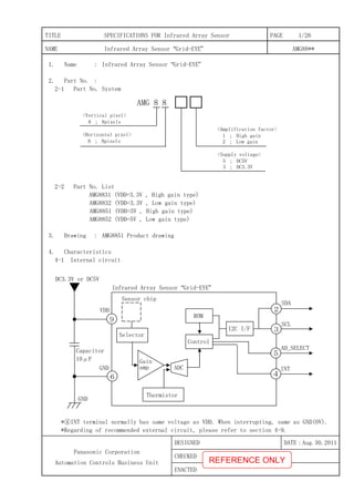
  • 1. TITLE SPECIFICATIONS FOR Infrared Array Sensor PAGE 1/26 NAME Infrared Array Sensor “Grid-EYE” AMG88** DESIGNED DATE:Aug.30.2011 CHECKED Panasonic Corporation Automation Controls Business Unit ENACTED 1. Name : Infrared Array Sensor “Grid-EYE” 2. Part No. : 2-1 Part No. System 2-2 Part No. List AMG8831 (VDD=3.3V , High gain type) AMG8832 (VDD=3.3V , Low gain type) AMG8851 (VDD=5V , High gain type) AMG8852 (VDD=5V , Low gain type) 3. Drawing : AMG8851 Product drawing 4. Characteristics 4-1 Internal circuit *④INT terminal normally has same voltage as VDD. When interrupting, same as GND(0V). *Regarding of recommended external circuit, please refer to section 4-9. AMG 8 8 <Amplification factor> 1 ; High gain 2 ; Low gain <Supply voltage> 5 ; DC5V 3 ; DC3.3V <Horizontal pixel> 8 ; 8pixels <Vertical pixel> 8 ; 8pixels Sensor chip VDD GND I2C I/F Thermistor Capacitor 10μF Infrared Array Sensor “Grid-EYE” 9 6 DC3.3V or DC5V GND SDA 2 SCL 3 INT AD_SELECT 5 4 Control ROM ADC Gain amp Selector REFERENCE ONLY
  • 2. TITLE SPECIFICATIONS FOR Infrared Array Sensor PAGE 2/26 NAME Infrared Array Sensor “Grid-EYE” AMG88** DATE:Aug.30.2011 Panasonic Corporation Automation Controls Business Unit 4-2 Main Functions Item Value Pixel number 64(8×8 Matrix) External Interface I2 C(fast mode) Frame rate Typ.10 frames/sec or Typ.1 frame/sec Operating Mode Normal Sleep Stand-by(10sec or 60sec intermittence) Output Mode Temperature Output Calculate Mode No moving average or Twice moving average Temperature Output Resolution 0.25℃ Number of Sensor Addresses 2(I2 C Slave Address) Thermistor Output Temperature Range -20℃~80℃ Thermistor Output Resolution 0.0625℃ 4-3 Absolute Maximum Ratings Item Specification Terminal Applied voltage -0.3~6.5V VDD, VPP Input/Output voltage -0.3~Vdd+0.3V SCL, SDA, AD_SELECT Output current -10~10mA INT, SDA ESD (Human Body Model) 1kV All Terminals ESD (Machine Model) 200V All Terminals 4-4 Ratings SpecificationItem High gain Low gain Applied voltage 3.3V±0.3V or 5.0V±0.5V Temperature Range of Measuring Object 0℃~80℃ -20℃~100℃ Operating temperature 0℃~80℃ -20℃~80℃ Storage temperature -20℃~80℃ REFERENCE ONLY
  • 3. TITLE SPECIFICATIONS FOR Infrared Array Sensor PAGE 3/26 NAME Infrared Array Sensor “Grid-EYE” AMG88** DATE:Aug.30.2011 Panasonic Corporation Automation Controls Business Unit 4-5 Characteristics SpecificationItem High gain Low gain Temperature Accuracy Within Typ.±2.5℃ Within Typ.±3.0℃ Rated detection distance *1 5m(Max.) Field of View Typ.60°(Horizontal, Vertical) Optical Axis Gap Within Typ.±5.6°(Horizontal, Vertical) Current Consumption Typ. 4.5mA(normal mode) Typ. 0.2mA(sleep mode) Typ. 0.8mA(stand-by mode) Setup Time Typ. 50msec(Time to enable Communication after Setup) Typ. 15sec(Time to stabilize Output after Setup) ※1 ・To have more than 4℃ of temperature difference from background ・Detection object size:700×250mm(Assumable human body size) 4-6 Electric characteristics (1) Characteristics of the SDA and SCL I/O stages parameter symbol Min. Max. unit Low level input voltage VIL -0.3 0.3×VDD V High level input voltage VIH 0.7×VDD VDD+0.3 V Hysteresis(SDA、SCL) Vhys 0.05×VDD V Low level output voltage (at 3mA sink current) VOL 0 0.4 V Output fall time from VIHmin to VILmax with a bus capacitance from 10pF to 400pF tof 20+Cb 250 ns Pulse width of spikes which must be suppressed by the input filter tSP 0 50 ns Input current each I/O pin with an input voltage between 0.1×VDD~0.9×VDD II -10 10 μA Capacitance for each I/O pin Ci - 10 pF REFERENCE ONLY
  • 4. TITLE SPECIFICATIONS FOR Infrared Array Sensor PAGE 4/26 NAME Infrared Array Sensor “Grid-EYE” AMG88** DATE:Aug.30.2011 Panasonic Corporation Automation Controls Business Unit (2) Characteristics of the SDA and SCL bus lines parameter symbol Min. Max. unit SCL clock frequency fSCL 0 400 kHz Hold time (repeated) START condition. tHD;STA 600 - ns Low period of the SCL clock tLOW 1.3 μs High period of the SCL clock THIGH 0.6 μs Set-up time for a repeated START condition tSU;STA 0.6 μs Data hold time tHD;DAT 0 900 ns Data set-up time tSU;DAT 100 ns Rise time of both SDA and SCL signals(fSCL>100kHz) tr 20+0.1 ×Cb 300 ns Rise time of both SDA and SCL signals(fSCL≦100kHz) tr 1000 ns Fall time of both SDA and SCL signals tf 20+0.1 ×Cb 300 ns Set-up time for STOP condition tSU;STO 600 ns Bus free time between a STOP and START condition tBUF 1300 ns Capacitive load for each bus line Cb 400 pF REFERENCE ONLY
  • 5. TITLE SPECIFICATIONS FOR Infrared Array Sensor PAGE 5/26 NAME Infrared Array Sensor “Grid-EYE” AMG88** DATE:Aug.30.2011 Panasonic Corporation Automation Controls Business Unit 4-7 Pixel Array & Viewing Field (1)Pixel Array Pixel Array from 1 to 64 is shown below. (2)Viewing Field Sensor Viewing Field(Typical)is shown below. 64 63 62 61 60 59 58 57 56 55 54 53 52 51 50 49 48 47 46 45 44 43 42 41 40 39 38 37 36 35 34 33 32 31 30 29 28 27 26 25 24 23 22 21 20 19 18 17 16 15 14 13 12 11 10 9 8 7 6 5 4 3 2 1 Horizontal viewing angle 60° Verticalviewingangle60° REFERENCE ONLY
  • 6. TITLE SPECIFICATIONS FOR Infrared Array Sensor PAGE 6/26 NAME Infrared Array Sensor “Grid-EYE” AMG88** DATE:Aug.30.2011 Panasonic Corporation Automation Controls Business Unit (3)Typical characteristics : Each pixel’s viewing central angle *Regarding of Pixel Array, please refer to 4-7(1). Sensor’s optical center (the origin of graph below) gap :within Typ.±5.6°(Both of horizontal and vertical directions) -40 -30 -20 -10 0 10 20 30 40 -40 -20 0 20 40 横方向の視野中心角(°) 縦方向の視野中心角(°) (4)Typical characteristics : Each pixel’s viewing angle(half angle) Central 4 pixels(Pixel No. 28, 29, 36, 37)viewing angle (half angle) : horizontal direction Typ.7.7° vertical direction Typ.8° 0 5 10 15 20 1 5 9 13 17 21 25 29 33 37 41 45 49 53 57 61 画素番号 各画素の横方向視野角(°) 0 5 10 15 20 1 5 9 13 17 21 25 29 33 37 41 45 49 53 57 61 画素番号 各画素の縦方向視野角(°) Each pixel’s Horizontal viewing angle Each pixel’s vertical viewing angle Horizontal viewing central angle(°) Verticalviewingcentralangle(°) Eachpixel’sHorizontalviewingangle(°) Eachpixel’sVerticalviewingangle(°) Pixel Number Pixel Number REFERENCE ONLY
  • 7. TITLE SPECIFICATIONS FOR Infrared Array Sensor PAGE 7/26 NAME Infrared Array Sensor “Grid-EYE” AMG88** DATE:Aug.30.2011 Panasonic Corporation Automation Controls Business Unit 4-8 Terminal’s Function Please refer to product drawing about pin assignment. *Please don’t connect wires in (NC) terminals. Terminal No. Name Function I/O Remarks ① (NC) - ② SDA I2 C data line I/O ③ SCL I2 C clock line I ④ INT Interrupt flag -This flag indicates whether Interrupt is generated or not when INT control register is activated. ・High (VDD) : Interrupt is not generated ・Low (0V) : Interrupt is generated O Please refer to section 4-10(4) ⑤ AD_SELECT Sensor address setting -2 number settable with connecting to VDD or GND. I Please refer to section 4-9 ⑥ GND 0V I ⑦ (NC) - ⑧ (NC) - ⑨ VDD DC3.3V or DC5V I ⑩ AVDD-PC Capacitor connected I Please refer to section 4-9 ⑪ (NC) - ⑫ DVDD-PC Capacitor connected I Please refer to section 4-9 ⑬ VPP VDD connection I ⑭ (NC) - REFERENCE ONLY
  • 8. TITLE SPECIFICATIONS FOR Infrared Array Sensor PAGE 8/26 NAME Infrared Array Sensor “Grid-EYE” AMG88** DATE:Aug.30.2011 Panasonic Corporation Automation Controls Business Unit 4-9 Recommended External Circuit This circuit is an example to drive Infrared Array Sensor “Grid-EYE”, so that our company will not take any responsibility of loss which is due to this circuit. (1)In case of setting I2 C slave address of the sensor 1101 000 *Connect Terminal⑤(AD_SELECT Terminal)to GND. (2)In case of setting I2 C slave address of the sensor 1101 001 *Connect Terminal⑤(AD_SELECT Terminal)to VDD. To microcomputer etc. To microcomputer etc. To microcomputer etc. To microcomputer etc. To microcomputer etc. To microcomputer etc. REFERENCE ONLY
  • 9. TITLE SPECIFICATIONS FOR Infrared Array Sensor PAGE 9/26 NAME Infrared Array Sensor “Grid-EYE” AMG88** DATE:Aug.30.2011 Panasonic Corporation Automation Controls Business Unit 4-10 Description of Functions Registers shown below are possible to be set optionally. Take care to avoid writing register and bit which are not specified, it may cause of making proper operation impossible and causing a deterioration in its performance. (1) Power Control Register Register for setting operating mode of device. With setting provided command, changing to each operating mode is possible. *Writing operation in Sleep mode is only active in return to Normal mode. (Command 0x00) *Reading operation in Sleep mode is invalid. address register R/W bit7 bit6 bit5 bit4 bit3 bit2 bit1 bit0 Initial value 0x00 PCTL R/W PCTL [7:0] 0x00 Command Operating mode 0x00 Normal mode 0x10 Sleep mode 0x20 Stand-by mode (60sec intermittence) 0x21 Stand-by mode (10sec intermittence) Normal mode Sleep mode Stand-by mode 0x00 0x00 0x10 0x10 0x20, 0x21 【Trandition Diagram of Operating mode】 POR Normal mode Sleep mode Stand-by mode 0x00 0x00 0x10 0x10 0x20, 0x21 【Trandition Diagram of Operating mode】 POR REFERENCE ONLY
  • 10. TITLE SPECIFICATIONS FOR Infrared Array Sensor PAGE 10/26 NAME Infrared Array Sensor “Grid-EYE” AMG88** DATE:Aug.30.2011 Panasonic Corporation Automation Controls Business Unit (2) Reset Register Register only for writing to reset software. Writing in specific code and register makes Software Reset possible. There are two kinds of Software Reset. ① Flag Reset can all clear the Status Register(0x04),Interrupt Flag, and Interrupt Table(0x10~0x17). ② Initial Reset brings Flag reset and returns to initial setting. address register R/W bit7 bit6 bit5 bit4 bit3 bit2 bit1 bit0 Initial value 0x01 RST W RST [7:0] 0x00 command Operating mode 0x30 Flag reset 0x3F Initial reset else - (3) Frame Rate Register Register for setting Frame Rate. bit0: Setting Frame Mode 1: 1FPS 0: 10FPS address register R/W bit7 bit6 bit5 bit4 bit3 bit2 bit1 bit0 Initial value 0x02 FPSC R/W - - - - - - - FPS 0x00 (4) Interrupt Control Register Register for setting Interrupt Function. bit1: INTMOD 1: Absolute Value Interrupt Mode 0: Difference Interrupt Mode bit0: INTEN 1: INT Output active 0: INT Output reactive(Hi-Z) address register R/W bit7 bit6 bit5 bit4 bit3 bit2 bit1 bit0 Initial value 0x03 INTC R/W - - - - - - INTMOD INTEN 0x00 REFERENCE ONLY
  • 11. TITLE SPECIFICATIONS FOR Infrared Array Sensor PAGE 11/26 NAME Infrared Array Sensor “Grid-EYE” AMG88** DATE:Aug.30.2011 Panasonic Corporation Automation Controls Business Unit (5) Status Register Register for only reading to indicate Overflow Flag and Interrupt Flag. bit3: OVF_THS 1: Thermistor Temperature Output Overflow (Value of Thermistor (0x0E、0x0F) : 0xFFF) bit2: OVF_IRS 1: Temperature Output Overflow (Value of Temperature Register(0x80~0xFF): 0xFFF) bit1: INTF 1: Interrupt Outbreak (Value of Interrupt Table Register(0x10~0x17): Except for 0x00) address register R/W bit7 bit6 bit5 bit4 bit3 bit2 bit1 bit0 Initial value 0x04 STAT R - - - - OVF_THS OVF_IRS INTF - 0x00 (6) Status Clear Register Register for only writing to clear the Overflow Flag and Interrupt Flag. After writing, automatically turns 0x00. bit3: OVT_CLR 1: Thermistor Temperature Output Overflow Flag Clear bit2: OVS_CLR 1: Temperature Output Overflow Flag Clear bit1: INTCLR 1: Interrupt Flag Clear address register R/W bit7 bit6 bit5 bit4 bit3 bit2 bit1 bit0 Initial value 0x05 SCLR W - - - - OVT_CLR OVS_CLR INTCLR - 0x00 REFERENCE ONLY
  • 12. TITLE SPECIFICATIONS FOR Infrared Array Sensor PAGE 12/26 NAME Infrared Array Sensor “Grid-EYE” AMG88** DATE:Aug.30.2011 Panasonic Corporation Automation Controls Business Unit (7) Average Register Register for setting moving average Output Mode. bit5: MAMOD 1: Twice moving average Output Mode address register R/W bit7 bit6 bit5 bit4 bit3 bit2 bit1 bit0 Initial value 0x07 AVE R/W - - MAMOD - - - - - 0x00 The method of setting moving average output mode is shown below. In case of setting on) In case of setting off) address R/W value 0x1F W 0x50 0x1F W 0x45 0x1F W 0x57 0x07 W 0x20 0x1F W 0x00 (8) Interrupt Level Register Register for setting upper / lower limit Hysteresis on Interrupt Level. 1 LSB has 12 bit resolution (11 bit + sign) which is equivalent to 0.25℃ and it is indicated as two's complement form. address register R/W bit7 bit6 bit5 bit4 bit3 bit2 bit1 bit0 Initial value 0x08 INTHL INT_LVL_H [7:0] 0x09 INTHH - INT_LVL_H [11:8] 0x0A INTLL INT_LVL_L [7:0] 0x0B INTLH - INT_LVL_L [11:8] 0x0C IHYSL INT_HYS [7:0] 0x0D IHYSH R/W - INT_HYS [11:8] 0x00 INT_LVL_H [11:0]: Interrupt Level upper limit setting when the value is upper than the set value, Interrupt Output and Interrupt Pixel Table are set. INT_LVL_L [11:0]: Interrupt Level lower limit setting when the value is lower than the set value, Interrupt Output and Interrupt Pixel Table are set. INT_HYS [11:0]: Setting of Interrupt Hysteresis Level when Interrupt is generated, set Hysteresis Level applied to Interrupt Level upper / lower value. When the value is set over Interrupt Level, Interrupt Output cannot be correct. address R/W value 0x1F W 0x50 0x1F W 0x45 0x1F W 0x57 0x07 W 0x00 0x1F W 0x00 REFERENCE ONLY
  • 13. TITLE SPECIFICATIONS FOR Infrared Array Sensor PAGE 13/26 NAME Infrared Array Sensor “Grid-EYE” AMG88** DATE:Aug.30.2011 Panasonic Corporation Automation Controls Business Unit (9) Thermistor Register Thermistor Temperature Register is a read only register which indicate Thermistor Temperature Data. Temperature Data is 12 bit data and 2 byte data. 1 LSB has 12 bit resolution which is equivalent to 0.0625℃ and it is indicated as code + absolute value. Main temperature data are shown below. address register R/W bit7 bit6 bit5 bit4 bit3 bit2 bit1 bit0 Initial value 0x0E TTHL R T7 T6 T5 T4 T3 T2 T1 T0 0x00 0x0F TTHH R - - - - +/- T10 T9 T8 0x00 temperature Binary number HEX number +125℃ 0111_1101_0000 0x7D0 +25℃ 0001_1001_0000 0x190 +0.25℃ 0000_0000_0100 0x004 0℃ 0000_0000_0000 0x000 -0.25℃ 1000_0000_0100 0x804 -20℃ 1001_0100_0000 0x940 (10)Interrupt Table Register Register for reading only to indicate pixels which temperature outputs are over the threshold. address register R/W bit7 bit6 bit5 bit4 bit3 bit2 bit1 bit0 Initial value 0x10 INT0 R PIX08 PIX07 PIX06 PIX05 PIX04 PIX03 PIX02 PIX01 0x00 0x11 INT1 R PIX16 PIX15 PIX14 PIX13 PIX12 PIX11 PIX10 PIX09 0x00 0x12 INT2 R PIX24 PIX23 PIX22 PIX21 PIX20 PIX19 PIX18 PIX17 0x00 0x13 INT3 R PIX32 PIX31 PIX30 PIX29 PIX28 PIX27 PIX26 PIX25 0x00 0x14 INT4 R PIX40 PIX39 PIX38 PIX37 PIX36 PIX35 PIX34 PIX33 0x00 0x15 INT5 R PIX48 PIX47 PIX46 PIX45 PIX44 PIX43 PIX42 PIX41 0x00 0x16 INT6 R PIX56 PIX55 PIX54 PIX53 PIX52 PIX51 PIX50 PIX49 0x00 0x17 INT7 R PIX64 PIX63 PIX62 PIX61 PIX60 PIX59 PIX58 PIX57 0x00 PIXn: Setting pixels over the threshold. 1: Pixel* interrupt is generated. 0: Pixel* interrupt is not generated. Interrupt Table is renewed in timing with when output data is renewed. Interrupt Table is possible to be cleared by reset resister. REFERENCE ONLY
  • 14. TITLE SPECIFICATIONS FOR Infrared Array Sensor PAGE 14/26 NAME Infrared Array Sensor “Grid-EYE” AMG88** DATE:Aug.30.2011 Panasonic Corporation Automation Controls Business Unit (11) Temperature Register Register for reading only to indicate temperature data per 1 pixel. Temperature Data of each pixel is 12 bit data and 2 byte data. 1 LSB has 12 bit resolution (11 bit + sign) which is equivalent to 0.25℃ and it is indicated as two's complement form. Main temperature data are shown below. address register R/W bit7 bit6 bit5 bit4 bit3 bit2 bit1 bit0 Initial value 0x80 T01L R T7 T6 T5 T4 T3 T2 T1 T0 0x00 0x81 T01H R - - - - +/- T10 T9 T8 0x00 temperature Binary number HEX number +125℃ 0001_1111_0100 0x1F4 +25℃ 0000_0110_0100 0x064 +0.25℃ 0000_0000_0001 0x001 0℃ 0000_0000_0000 0x000 -0.25℃ 1111_1111_1111 0xFFF -25℃ 1111_1001_1100 0xF9C -55℃ 1111_0010_0100 0xF24 Supplement) Temperature Data of Pixel 1~64(0x80~0xFF)are renewed in a lump in timing with no instruction from external Master. (Renewal time depends on the setting frame rate.) Because of reading 0x80~0xFF at once, old and new temperature data never be mingled in 64 pixels data. REFERENCE ONLY
  • 15. TITLE SPECIFICATIONS FOR Infrared Array Sensor PAGE 15/26 NAME Infrared Array Sensor “Grid-EYE” AMG88** DATE:Aug.30.2011 Panasonic Corporation Automation Controls Business Unit 4-11 Register Map ※Read/Write column R/W:both of Read & Write,R:Read only,W:Write only Address Register Name Read/Write Description Initial value 0x00 PCTL R/W Set operating mode(Normal, Sleep etc.) 0x00 0x01 RST W Software Reset 0x00 0x02 FPSC R/W Frame rate 0x00 0x03 INTC R/W Interrupt Function 0x00 0x04 STAT R Interrupt Flag, low voltage Flag 0x00 0x05 SCLR W Interrupt Flag Clear 0x00 0x06 Reserved 0x07 AVE R Moving Average Output Mode 0x00 0x08 INTHL R/W Interrupt upper value(Upper level) 0x00 0x09 INTHH R/W Interrupt upper value(Upper level) 0x00 0x0A INTLL R/W Interrupt lower value(Lower level) 0x00 0x0B INTLH R/W Interrupt lower value(upper level) 0x00 0x0C IHYSL R/W Interrupt hysteresis value(Lower level) 0x00 0x0D IHYSH R/W Interrupt hysteresis value(Upper level) 0x00 0x0E TTHL R Thermistor Output Value(Lower level) 0x00 0x0F TTHH R Thermistor Output Value(Upper level) 0x00 0x10 INT0 R Pixel 1~8 Interrupt Result 0x00 0x11 INT1 R Pixel 9~16 Interrupt Result 0x00 0x12 INT2 R Pixel 17~24 Interrupt Result 0x00 0x13 INT3 R Pixel 25~32 Interrupt Result 0x00 0x14 INT4 R Pixel 33~40 Interrupt Result 0x00 0x15 INT5 R Pixel 41~48 Interrupt Result 0x00 0x16 INT6 R Pixel 49~56 Interrupt Result 0x00 0x17 INT7 R Pixel 57~64 Interrupt Result 0x00 0x18 Reserved 0x19 Reserved 0x1A Reserved 0x1B Reserved 0x1C Reserved 0x1D Reserved 0x1E Reserved 0x1F Reserved REFERENCE ONLY
  • 16. TITLE SPECIFICATIONS FOR Infrared Array Sensor PAGE 16/26 NAME Infrared Array Sensor “Grid-EYE” AMG88** DATE:Aug.30.2011 Panasonic Corporation Automation Controls Business Unit Address Register Name Read/Write Description Initial value 0x80 T01L R Pixel 1 Output Value (Lower Level) 0x00 0x81 T01H R Pixel 1 Output Value (Upper Level) 0x00 0x82 T02L R Pixel 2 Output Value (Lower Level) 0x00 0x83 T02H R Pixel 2 Output Value (Upper Level) 0x00 0x84 T03L R Pixel 3 Output Value (Lower Level) 0x00 0x85 T03H R Pixel 3 Output Value (Upper Level) 0x00 0x86 T04L R Pixel 4 Output Value (Lower Level) 0x00 0x87 T04H R Pixel 4 Output Value (Upper Level) 0x00 0x88 T05L R Pixel 5 Output Value (Lower Level) 0x00 0x89 T05H R Pixel 5 Output Value (Upper Level) 0x00 0x8A T06L R Pixel 6 Output Value (Lower Level) 0x00 0x8B T06H R Pixel 6 Output Value (Upper Level) 0x00 0x8C T07L R Pixel 7 Output Value (Lower Level) 0x00 0x8D T07H R Pixel 7 Output Value (Upper Level) 0x00 0x8E T08L R Pixel 8 Output Value (Lower Level) 0x00 0x8F T08H R Pixel 8 Output Value (Upper Level) 0x00 0x90 T09L R Pixel 9 Output Value (Lower Level) 0x00 0x91 T09H R Pixel 9 Output Value (Upper Level) 0x00 0x92 T10L R Pixel 10 Output Value (Lower Level) 0x00 0x93 T10H R Pixel 10 Output Value (Upper Level) 0x00 0x94 T11L R Pixel 11 Output Value (Lower Level) 0x00 0x95 T11H R Pixel 11 Output Value (Upper Level) 0x00 0x96 T12L R Pixel 12 Output Value (Lower Level) 0x00 0x97 T12H R Pixel 12 Output Value (Upper Level) 0x00 0x98 T13L R Pixel 13 Output Value (Lower Level) 0x00 0x99 T13H R Pixel 13 Output Value (Upper Level) 0x00 0x9A T14L R Pixel 14 Output Value (Lower Level) 0x00 0x9B T14H R Pixel 14 Output Value (Upper Level) 0x00 0x9C T15L R Pixel 15 Output Value (Lower Level) 0x00 0x9D T15H R Pixel 15 Output Value (Upper Level) 0x00 0x9E T16L R Pixel 16 Output Value (Lower Level) 0x00 0x9F T16H R Pixel 16 Output Value (Upper Level) 0x00 REFERENCE ONLY
  • 17. TITLE SPECIFICATIONS FOR Infrared Array Sensor PAGE 17/26 NAME Infrared Array Sensor “Grid-EYE” AMG88** DATE:Aug.30.2011 Panasonic Corporation Automation Controls Business Unit Address Register Name Read/Write Description Initial value 0xA0 T17L R Pixel 17 Output Value (Lower Level) 0x00 0xA1 T17H R Pixel 17 Output Value (Upper Level) 0x00 0xA2 T18L R Pixel 18 Output Value (Lower Level) 0x00 0xA3 T18H R Pixel 18 Output Value (Upper Level) 0x00 0xA4 T19L R Pixel 19 Output Value (Lower Level) 0x00 0xA5 T19H R Pixel 19 Output Value (Upper Level) 0x00 0xA6 T20L R Pixel 20 Output Value (Lower Level) 0x00 0xA7 T20H R Pixel 20 Output Value (Upper Level) 0x00 0xA8 T21L R Pixel 21 Output Value (Lower Level) 0x00 0xA9 T21H R Pixel 21 Output Value (Upper Level) 0x00 0xAA T22L R Pixel 22 Output Value (Lower Level) 0x00 0xAB T22H R Pixel 22 Output Value (Upper Level) 0x00 0xAC T23L R Pixel 23 Output Value (Lower Level) 0x00 0xAD T23H R Pixel 23 Output Value (Upper Level) 0x00 0xAE T24L R Pixel 24 Output Value (Lower Level) 0x00 0xAF T24H R Pixel 24 Output Value (Upper Level) 0x00 0xB0 T25L R Pixel 25 Output Value (Lower Level) 0x00 0xB1 T25H R Pixel 25 Output Value (Upper Level) 0x00 0xB2 T26L R Pixel 26 Output Value (Lower Level) 0x00 0xB3 T26H R Pixel 26 Output Value (Upper Level) 0x00 0xB4 T27L R Pixel 27 Output Value (Lower Level) 0x00 0xB5 T27H R Pixel 27 Output Value (Upper Level) 0x00 0xB6 T28L R Pixel 28 Output Value (Lower Level) 0x00 0xB7 T28H R Pixel 28 Output Value (Upper Level) 0x00 0xB8 T29L R Pixel 29 Output Value (Lower Level) 0x00 0xB9 T29H R Pixel 29 Output Value (Upper Level) 0x00 0xBA T30L R Pixel 30 Output Value (Lower Level) 0x00 0xBB T30H R Pixel 30 Output Value (Upper Level) 0x00 0xBC T31L R Pixel 31 Output Value (Lower Level) 0x00 0xBD T31H R Pixel 31 Output Value (Upper Level) 0x00 0xBE T32L R Pixel 32 Output Value (Lower Level) 0x00 0xBF T32H R Pixel 32 Output Value (Upper Level) 0x00 REFERENCE ONLY
  • 18. TITLE SPECIFICATIONS FOR Infrared Array Sensor PAGE 18/26 NAME Infrared Array Sensor “Grid-EYE” AMG88** DATE:Aug.30.2011 Panasonic Corporation Automation Controls Business Unit Address Register Name Read/Write Description Initial value 0xC0 T33L R Pixel 33 Output Value (Lower Level) 0x00 0xC1 T33H R Pixel 33 Output Value (Upper Level) 0x00 0xC2 T34L R Pixel 34 Output Value (Lower Level) 0x00 0xC3 T34H R Pixel 34 Output Value (Upper Level) 0x00 0xC4 T35L R Pixel 35 Output Value (Lower Level) 0x00 0xC5 T35H R Pixel 35 Output Value (Upper Level) 0x00 0xC6 T36L R Pixel 36 Output Value (Lower Level) 0x00 0xC7 T36H R Pixel 36 Output Value (Upper Level) 0x00 0xC8 T37L R Pixel 37 Output Value (Lower Level) 0x00 0xC9 T37H R Pixel 37 Output Value (Upper Level) 0x00 0xCA T38L R Pixel 38 Output Value (Lower Level) 0x00 0xCB T38H R Pixel 38 Output Value (Upper Level) 0x00 0xCC T39L R Pixel 39 Output Value (Lower Level) 0x00 0xCD T39H R Pixel 39 Output Value (Upper Level) 0x00 0xCE T40L R Pixel 40 Output Value (Lower Level) 0x00 0xCF T40H R Pixel 40 Output Value (Upper Level) 0x00 0xD0 T41L R Pixel 41 Output Value (Lower Level) 0x00 0xD1 T41H R Pixel 41 Output Value (Upper Level) 0x00 0xD2 T42L R Pixel 42 Output Value (Lower Level) 0x00 0xD3 T42H R Pixel 42 Output Value (Upper Level) 0x00 0xD4 T43L R Pixel 43 Output Value (Lower Level) 0x00 0xD5 T43H R Pixel 43 Output Value (Upper Level) 0x00 0xD6 T44L R Pixel 44 Output Value (Lower Level) 0x00 0xD7 T44H R Pixel 44 Output Value (Upper Level) 0x00 0xD8 T45L R Pixel 45 Output Value (Lower Level) 0x00 0xD9 T45H R Pixel 45 Output Value (Upper Level) 0x00 0xDA T46L R Pixel 46 Output Value (Lower Level) 0x00 0xDB T46H R Pixel 46 Output Value (Upper Level) 0x00 0xDC T47L R Pixel 47 Output Value (Lower Level) 0x00 0xDD T47H R Pixel 47 Output Value (Upper Level) 0x00 0xDE T48L R Pixel 48 Output Value (Lower Level) 0x00 0xDF T48H R Pixel 48 Output Value (Upper Level) 0x00 REFERENCE ONLY
  • 19. TITLE SPECIFICATIONS FOR Infrared Array Sensor PAGE 19/26 NAME Infrared Array Sensor “Grid-EYE” AMG88** DATE:Aug.30.2011 Panasonic Corporation Automation Controls Business Unit Address Register Name Read/Write Description Initial value 0xE0 T49L R Pixel 49 Output Value (Lower Level) 0x00 0xE1 T49H R Pixel 49 Output Value (Upper Level) 0x00 0xE2 T50L R Pixel 50 Output Value (Lower Level) 0x00 0xE3 T50H R Pixel 50 Output Value (Upper Level) 0x00 0xE4 T51L R Pixel 51 Output Value (Lower Level) 0x00 0xE5 T51H R Pixel 51 Output Value (Upper Level) 0x00 0xE6 T52L R Pixel 52 Output Value (Lower Level) 0x00 0xE7 T52H R Pixel 52 Output Value (Upper Level) 0x00 0xE8 T53L R Pixel 53 Output Value (Lower Level) 0x00 0xE9 T53H R Pixel 53 Output Value (Upper Level) 0x00 0xEA T54L R Pixel 54 Output Value (Lower Level) 0x00 0xEB T54H R Pixel 54 Output Value (Upper Level) 0x00 0xEC T55L R Pixel 55 Output Value (Lower Level) 0x00 0xED T55H R Pixel 55 Output Value (Upper Level) 0x00 0xEE T56L R Pixel 56 Output Value (Lower Level) 0x00 0xEF T56H R Pixel 56 Output Value (Upper Level) 0x00 0xF0 T57L R Pixel 57 Output Value (Lower Level) 0x00 0xF1 T57H R Pixel 57 Output Value (Upper Level) 0x00 0xF2 T58L R Pixel 58 Output Value (Lower Level) 0x00 0xF3 T58H R Pixel 58 Output Value (Upper Level) 0x00 0xF4 T59L R Pixel 59 Output Value (Lower Level) 0x00 0xF5 T59H R Pixel 59 Output Value (Upper Level) 0x00 0xF6 T60L R Pixel 60 Output Value (Lower Level) 0x00 0xF7 T60H R Pixel 60 Output Value (Upper Level) 0x00 0xF8 T61L R Pixel 61 Output Value (Lower Level) 0x00 0xF9 T61H R Pixel 61 Output Value (Upper Level) 0x00 0xFA T62L R Pixel 62 Output Value (Lower Level) 0x00 0xFB T62H R Pixel 62 Output Value (Upper Level) 0x00 0xFC T63L R Pixel 63 Output Value (Lower Level) 0x00 0xFD T63H R Pixel 63 Output Value (Upper Level) 0x00 0xFE T64L R Pixel 64 Output Value (Lower Level) 0x00 0xFF T64H R Pixel 64 Output Value (Upper Level) 0x00 REFERENCE ONLY
  • 20. TITLE SPECIFICATIONS FOR Infrared Array Sensor PAGE 20/26 NAME Infrared Array Sensor “Grid-EYE” AMG88** DATE:Aug.30.2011 Panasonic Corporation Automation Controls Business Unit 5. Lot No. of manufactured □□ □□ □□ Data of manufactured : Expressed in two digits. ※ first → 01 Month of manufactured : Expressed in two digits. ※ January → 01 Year of manufactured : Expressed in last two digits of the year. ※ 2011 → 11 6. Safety Precautions ! Safety Precautions Head the following precautions to prevent injury or accidents. ①Do not use these sensors under any circumstance in which the range of their ratings, environment conditions or other specifications are exceeded. Using the sensors in any way which causes their specifications to be exceeded may generate abnormally high levels of heat, emit smoke, etc., resulting in damage to the circuitry and possibly causing an accident. ②Before connecting a connector, check the pin layout by referring to the connector wiring diagram, specifications diagram, etc., and make sure that the connector is connected properly. Take note that mistakes made in connection may cause unforeseen problems in operation, generate abnormally high levels of heat, emit smoke, etc., resulting in damage to the circuitry. ③Do not use any Infrared Array Sensor which has been disassembled or remodeled. ④Failure modes of sensors include short-circuiting, open-circuiting and temperature rises. If this sensor is to be used in equipment where safety is a prime consideration, examine the possible effects of these failures on the equipment concerned, and ensure safety by providing protection circuits or protection devices. Example : ・Safety equipments and devices ・Traffic signals ・Burglar and disaster prevention devices ・Control and safety device for trains and motor vehicles ・Temperature control device using sensor output data. Etc. REFERENCE ONLY
  • 21. TITLE SPECIFICATIONS FOR Infrared Array Sensor PAGE 21/26 NAME Infrared Array Sensor “Grid-EYE” AMG88** DATE:Aug.30.2011 Panasonic Corporation Automation Controls Business Unit 7.NOTES 7-1 Checkpoints relating to principle of operation The Infrared Array Sensor is a thermopile-typed infrared sensor which detects quantity of infrared ray. Generally, temperature accuracy will be degraded in the following situations. Be sure to verify performance and reliability under actual conditions of use and make any necessary temperature corrections. ・There is a heat emitting body located close to where the sensor is mounted. ・A flow of warm or cold air is hitting the sensor. ・The temperature of the sensor is subject to sudden change. ・When an object made of glass, acrylic or other subject which far infrared rays have difficult passing through is located between the sensor and what is to be detected. ・A substance (dirt or water droplets) that makes it difficult for far infrared rays to pass through is attached to the sensor lens. 7-2 Ambient operating conditions (1) Temperature : Please refer to Ratings. (2) Humidity : 15% to 85% R.H. (No freezing nor condensation at low temperature) (3) Atmospheric pressure : 86 to 106 kPa (4) Protect the sensor from impact and vibration, because there can cause damage that leads to malfunction and degraded performance. And avoid applying a load or impact since this will deform or scratch the lens, making proper operation impossible and causing a deterioration in its performance. (5) The sensors do not have a water-proof or dust-proof construction. Depending on the ambient operating conditions, some means of providing protection from water and dust and preventing the formation of ice and condensation must be provided prior to using the sensor. If condensation occurs, heat source detection response may become delayed by several seconds. (6) Please avoid using or storing the pressure sensor chip in a place exposed to corrosive gases (such as the gases given off by organic solvents, sulfurous acid gas, hydrogen sulfides, etc.) which will adversely affect the performance of the infrared array sensor. (7) Since the internal circuitry may be destroyed if an external surge voltages is supplied, provide an element which will absorb the surges. (8) Malfunctioning may occur if the product is in the vicinity of electrical noise such as that from static electricity, lightning, a mobile phone, an amateur radio, broadcasting station. REFERENCE ONLY
  • 22. TITLE SPECIFICATIONS FOR Infrared Array Sensor PAGE 22/26 NAME Infrared Array Sensor “Grid-EYE” AMG88** DATE:Aug.30.2011 Panasonic Corporation Automation Controls Business Unit (9) Although the ambient temperature (humidity) range is a temperature (humidity) range which can operate a sensor continuously, the humidity range changes with temperature. So please use it in the humidity range shown below. And please avoid continuation use near a limit. Generally under high temperature or high humidity, deterioration of electronic parts accelerates. To ensure reliability, please verify quality under conditions of actual use. This humidity range does not guarantee durability ability. 7-3 Mounting ・Use lands on the printed-circuit boards to which the sensor can be securely fixed. ・Recommended printed-circuit board is FR4 (thickness 1.6mm). ・As for mounting unrecommended printed-circuit board, Please verify quality in advance. ・Malfunctioning may occur if much noise is present in the power supply used for this sensor. In order to prevent, in particular, superimposed noise, please install the recommended capacitor between the sensor input terminals (between VDD and GND) closest to the sensor (a position within 20 mm of the pattern circuit length). However, please reselect an ideal capacitor after performing tests on the actual equipment. ・Since the top surface (where the part number is visible) of the sensor is GND, please make sure that the metallic parts of other components do not come into contact. 7-4 Soldering Due to the thermal capacity of the infrared array sensor is low, therefore, take steps to minimize the effects of external heat. Damage and changes to characteristics may occur due to heat deformation. Use a non-corrosive resin type of flux. (1) Manual soldering ・Set the soldering tip from 350 to 400℃(30-60W), and solder within 3 seconds or less. ・Please note that output may be changed if the load is applied to the terminals when the soldering. ・Carefully clean the tip of soldering iron. 85 800-20 15 ・High gain type(AMG8831,AMG8851) ・Low gain type(AMG8832,AMG8852) Ambient temperature(℃) 800-20 Humidity (%RH) Avoid freezing when used at temperatures lower than 0℃ Tolerance range 85 15 Humidity (%RH) Tolerance range Ambient temperature(℃) Avoid condensation when used at temperatures higher than 0℃ Avoid condensation when used at temperatures higher than 0℃ REFERENCE ONLY
  • 23. TITLE SPECIFICATIONS FOR Infrared Array Sensor PAGE 23/26 NAME Infrared Array Sensor “Grid-EYE” AMG88** DATE:Aug.30.2011 Panasonic Corporation Automation Controls Business Unit (2) Reflow soldering ・The recommended reflow temperature profile conditions are given below. ・We recommend the screen solder printing method as the method of cream. ・Please refer to the recommended PC board specification diagram for the PC board foot pattern. ・Self alignment may not always work as expected, therefore, please carefully the position of the terminals and pattern. ・The temperature of the profile is assumed to be a value measured with the printed wiring board of the terminal neighborhood. ・When you do the reflow solder to the back of the PC board after the reflow of the sensor, please execute fixed processing,for instance, with the adhesive etc. (3) Solder reworking ・Finish reworking in one operation. ・For reworking of the solder bridge, use a soldering iron with a flat tip. Please do not add more flux when reworking. ・The temperature of the soldering tip must be under the above-mentioned temperature. (4) When you cut or fold the PC board after mounting the sensor, be careful not to stress to the soldered parts. (5) The sensor terminals are designed to be exposed, so contact of the terminals with metal shards and the like will cause output errors. Therefore, please be careful not to touch the terminals with the metal piece or the hand. (6) To prevent the insulation of the PC board after soldering, please be careful not to place the chemicals on the sensor when coating. T3 T1 T2 t1 t2 Time T1=150~180℃ T2=230℃ T3=Within 250℃ t1=60~120 seconds t2=Within 30 seconds Peak temperature REFERENCE ONLY
  • 24. TITLE SPECIFICATIONS FOR Infrared Array Sensor PAGE 24/26 NAME Infrared Array Sensor “Grid-EYE” AMG88** DATE:Aug.30.2011 Panasonic Corporation Automation Controls Business Unit 7-5 Connections ・Please perform connections correctly in accordance with the terminal connection diagram. In particular, be careful not to reverse wire the power supply as this will cause damage or degrade to the sensor. ・Please do not connect wires in an empty terminal. It causes the sensor breakdown. ・When using the sensors with cables, it is recommended that cables which are shielded and as short as possible be used in order to safeguard against the effects of noise. 7-6 Cleaning Avoid ultrasonic cleaning since this may cause breaks or disconnections in the wiring. 7-7 Transportation and storage (1) Extreme vibration and shock during transport will damage the sensor. Handle the outer box and reel with care. (2) Storage under extreme conditions will cause soldering degradation, external appearance defects, and deterioration of the characteristics. The following storage conditions are recommended. ・Temperature : 0 to 45℃ ・Humidity : less than 70% R.H. ・Atmosphere : No harmful gasses such as sulfurous acid gas, minimal dust. (3) The sensors are sensitive to moisture and come in moisture-proof packages. Observe the following cautions when storing. ・After the moisture-proof package is unsealed, take the sensors out of storage as soon as possible (within 1 week ≦ 30℃ 60% R.H.) ・If the sensors are to be left in storage for a considerable period after the moisture-proof package has been unsealed, it is recommended to keep them in another moisture-proof bag containing silica gel (within 3 months at the most). * When mounting with solder, if thermal stress is applied to sensors that have absorbed moisture, the moisture will vaporize, swelling will occur, and the inside of the package will become stressed. This may cause the package surface to blister or crack. Therefore, please take caution and observe the soldering conditions. REFERENCE ONLY
  • 25. TITLE SPECIFICATIONS FOR Infrared Array Sensor PAGE 25/26 NAME Infrared Array Sensor “Grid-EYE” AMG88** DATE:Aug.30.2011 Panasonic Corporation Automation Controls Business Unit 7-8 Other handling cautions To assure reliability, check the sensor under actual loading conditions. Avoid any situation that may adversely affect its performance. ・This product may malfunction if dropped on its own before it is installed. Do not use if this happens. ・Caution is required because writing except for register and bit specified in 4-10 can be cause of malfunction and performance degradation. ・Caution is required because differences in the temperature range and the method of connection can lead to breakdown. ・If the sensor get high frequency vibration, it can be cause of breakdown. When the product get impulse like below, do not use it. ①touch to a object made of metal ②touch of mutual sensors ・Since static charge can damage the sensor, bear in mind the following handling precautions. ①Plastic containers should not be used to store or transport the sensors since they readily become charged. ②Please store or transport the product in an environment that hinders the occurrence of static electricity (for example, places with 45% to 60% humidity) and protect the product using electrically conductive packaging. ③Implement static electricity prevention measures once the product packaging has been opened. • Any personnel handling the sensor should wear electrostatic clothing and be body grounded. • Place an electrically conducting board on the work surface and ground any devices used such as measuring instruments and jigs. • Use a soldering iron with a low leak current or else ground the tip. • Make sure that customer equipment used for device assembly is grounded. ④Since the internal circuitry may be destroyed if an external surge voltage is supplied, provide an element which will absorb the surges. REFERENCE ONLY
  • 26. TITLE SPECIFICATIONS FOR Infrared Array Sensor PAGE 26/26 NAME Infrared Array Sensor “Grid-EYE” AMG88** DATE:Aug.30.2011 Panasonic Corporation Automation Controls Business Unit 8. Special remarks Although the best attention will be paid for the quality controls of the products, please consider the followings : (1) To prevent unexpected failures as much as possible under the conditions not shown in this specifications, please let us know the detailed information on the application, such as the environmental, operational and mounting condition. (2) By any chance, if the failure of the product is considered to cause a personal injury or death or property damage, the safety rate should be added to the specified values shown in this specifications and the dual safety structure or circuit is recommended to be taken from the stand point of the Product Liability Indemnity. (3) We will either repair or replace any products or parts there of which prove to be defective against only the items written in this specifications within 1 year from the date of products acceptance at the site of delivery. (4) Following cases are not covered by this guarantee. ① The case of other damage caused by the failure or defect of the product. ② The case that the product condition changed by handling, storage and/or transportation after delivery. ③ The case caused by the phenomenon which has never been discovered and is impossible to be foreknown with the existing technologies. ④ The case of force majeure, such as acts of God, public enemy or war, fires, floods and any other causes beyond the control of the people concerned. 9. Export control 【To Customers in Japan】 This product is restricted under Japan’s “Foreign Exchange and Foreign Trade Law.” An export permit from the Japanese government is required when you export or take this product outside Japan. (As of Apr.2011) This product may not be used for any purpose other than those specified. Reselling the product to third parties is prohibited. When disposing of the product, it must first be converted into non-reusable and non-controlled form. 【To Customers Outside Japan】 This product is restricted under Japan’s laws and regulations relating to security export control (Foreign Exchange and Foreign Trade Law). We have obtained an export permit from the Japanese government to sell or provide this product to your company, subject to the following: This product may not be used for any purpose other than those specified. This product may be subject to further export restrictions under the laws and regulations of other countries (including your own). Reselling the product to third parties is prohibited. When disposing of the product, it must first be converted into non-reusable and non-controlled form. REFERENCE ONLY