1. Analog Servo Drive AZ20A8I
Description
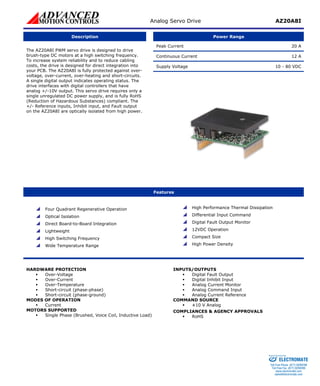
Power Range
Peak Current 20 A
Continuous Current 12 A
Supply Voltage 10 - 80 VDC
The AZ20A8I PWM servo drive is designed to drive brush-type DC motors at a high switching frequency. To increase system reliability and to reduce cabling costs, the drive is designed for direct integration into your PCB. The AZ20A8I is fully protected against over- voltage, over-current, over-heating and short-circuits. A single digital output indicates operating status. The drive interfaces with digital controllers that have analog +/-10V output. This servo drive requires only a single unregulated DC power supply, and is fully RoHS (Reduction of Hazardous Substances) compliant. The +/- Reference inputs, Inhibit input, and Fault output on the AZ20A8I are optically isolated from high power.
Features
Four Quadrant Regenerative Operation
Optical Isolation
Direct Board-to-Board Integration
Lightweight
High Switching Frequency
Wide Temperature Range
High Performance Thermal Dissipation
Differential Input Command
Digital Fault Output Monitor
12VDC Operation
Compact Size
High Power Density
HARDWARE PROTECTION
ƒ
Over-Voltage
ƒ
Over-Current
ƒ
Over-Temperature
ƒ
Short-circuit (phase-phase)
ƒ
Short-circuit (phase-ground)
MODES OF OPERATION
ƒ
Current
MOTORS SUPPORTED
ƒ
Single Phase (Brushed, Voice Coil, Inductive Load)
INPUTS/OUTPUTS
ƒ
Digital Fault Output
ƒ
Digital Inhibit Input
ƒ
Analog Current Monitor
ƒ
Analog Command Input
ƒ
Analog Current Reference
COMMAND SOURCE
ƒ
±10 V Analog
COMPLIANCES & AGENCY APPROVALS
ƒ
RoHS
ELECTROMATE
Toll Free Phone (877) SERVO98
Toll Free Fax (877) SERV099
www.electromate.com
sales@electromate.com
Sold & Serviced By:
2. Analog Servo Drive AZ20A8I
BLOCK DIAGRAM
Information on Approvals and Compliances
RoHS (Reduction of Hazardous Substances) is intended to prevent hazardous substances such as lead from being manufactured in electrical and electronic equipment.
ELECTROMATE
Toll Free Phone (877) SERVO98
Toll Free Fax (877) SERV099
www.electromate.com
sales@electromate.com
Sold & Serviced By:
3. Analog Servo Drive AZ20A8I
SPECIFICATIONS
Power Specifications
Description
Units
Value
DC Supply Voltage Range
VDC
10 - 80
DC Bus Over Voltage Limit
VDC
88
DC Bus Under Voltage Limit
VDC
9
Maximum Peak Output Current1
A
20
Maximum Continuous Output Current
A
12
Maximum Power Dissipation at Continuous Current
W
48
Minimum Load Inductance (Line-To-Line)2
μH
100
Switching Frequency
kHz
31
Control Specifications
Description
Units
Value
Command Sources
-
±10 V Analog
Modes of Operation
-
Current
Motors Supported
-
Single Phase (Brushed, Voice Coil, Inductive Load)
Hardware Protection
-
Over Current, Over Temperature, Over Voltage, Short Circuit (Phase-Phase & Phase-Ground)
Primary I/O Logic Level
-
5V TTL
Mechanical Specifications
Description
Units
Value
Agency Approvals
-
RoHS
Size (H x W x D)
mm (in)
63.5 x 50.8 x 22.9 (2.5 x 2 x 0.9)
Weight
g (oz)
94.5 (3.3)
Heatsink (Base) Temperature Range3
°C (°F)
0 - 75 (32 - 167)
Storage Temperature Range
°C (°F)
-40 - 85 (-40 - 185)
Form Factor
-
PCB Mounted
P1 Connector
-
16-pin, 2.54 mm spaced header
P2 Connector
-
22-pin, 2.54 mm spaced, dual-row header
Notes
1.
Maximum duration of peak current is ~2 seconds.
2.
Lower inductance is acceptable for bus voltages well below maximum. Use external inductance to meet requirements.
3.
Additional cooling and/or heatsink may be required to achieve rated performance.
ELECTROMATE
Toll Free Phone (877) SERVO98
Toll Free Fax (877) SERV099
www.electromate.com
sales@electromate.com
Sold & Serviced By:
4. Analog Servo Drive AZ20A8I
PIN FUNCTIONS
P1 - Signal Connector
Pin
Name
Description / Notes
I/O
1
+REF IN (ISO)
Differential Reference Input (±10 V Operating Range, ±15 V Maximum Input). Optically isolated from high voltage.
I
2
SIGNAL GND
Signal Ground (Isolated from Power Ground)
SGND
3
-REF IN (ISO)
Differential Reference Input (±10 V Operating Range, ±15 V Maximum Input). Optically isolated from high voltage.
I
4
CURRENT MONITOR
Current Monitor. Analog output signal proportional to the actual current output. Scaling is 6.4 A/V. Measure relative to power ground.
O
5
IN
HIBIT IN (ISO)
TTL level (+5 V) inhibit/enable input. Leave open to enable drive. Pull to signal ground to inhibit drive. Inhibit turns off all power devices. Optically isolated from high voltage.
I
6
+5V ISO INPUT
+5 V supply input for isolated signals. 20mA minimum.
I
7
SIGNAL GND
Signal Ground (Isolated from Power Ground)
SGND
8
NC
-
9
NC
-
10
NC
Not Connected (Reserved)
-
11
CURRENT REF OUT
Measures the command signal to the internal current-loop. This pin has a maximum output of ±7.45 V when the drive outputs maximum peak current. Measure relative to power ground.
O
12
FAULT OUT (ISO)
TTL level (+5 V) output becomes high when power devices are disabled due to at least one of the following conditions: inhibit, invalid Hall state, output short circuit, over voltage, over temperature, power-up reset. Optically isolated from high voltage.
O
13
NC
-
14
NC
-
15
NC
-
16
NC
Not Connected (Reserved)
-
P2 - Power Connector
Pin
Name
Description / Notes
I/O
1
1a
HIGH VOLTAGE
I
2b
2a
HIGH VOLTAGE
DC Power Input. 3A Continuous Current Rating Per Pin.
I
3b
NC
Not Connected (Reserved)
-
3a
NC (KEY)
Key: No Connection (pin removed)
-
4b
4a
PWR GND
PGND
5b
5a
PWR GND
Power Ground (Isolated from Signal Ground). 3A Continuous Current Rating Per Pin
PGND
6b
6a
NC
-
7b
7a
NC
Not Connected (Reserved)
-
8b
8a
MOTOR B
O
9b
9a
MOTOR B
Motor Phase B. 3A Continuous Current Rating Per Pin.
O
10b
10a
MOTOR A
O
11b
11a
MOTOR A
Motor Phase A. 3A Continuous Current Rating Per Pin.
O
HARDWARE SETTINGS
Jumper Settings
Jumper is a SMT, 0 ohm resistor located on the underside of the drive PCB. By default, the drive is configured with the jumper installed. Typical drive operation will not require the jumper to be removed. Please contact the factory before jumper removal.
Jumper
Description
Configuration
SMT Jumper (0Ω Resistor)
Not Installed
Installed
JE1
Inhibit logic. Sets the logic level of inhibit pins. Labeled JE1 on the PCB of the drive.
Low Enable
Low Inhibit
ELECTROMATE
Toll Free Phone (877) SERVO98
Toll Free Fax (877) SERV099
www.electromate.com
sales@electromate.com
Sold & Serviced By:
5. Analog Servo Drive AZ20A8I
MECHANICAL INFORMATION
P1 - Signal Connector
Connector Information
16-pin, 2.54 mm spaced header
Details
Samtec: BCS-116-L-S-PE
Mating Connector
Included with Drive
No +REF IN (ISO)1SIGNAL GND2-REF IN (ISO)3CURRENT MONITOR4INHIBIT IN (ISO)5+5V ISO INPUT6SIGNAL GND7NC8NC9NC10CURRENT REF OUT11FAULT OUT (ISO)12 NC13NC15
P2 - Power Connector
Connector Information
22-pin, 2.54 mm spaced, dual-row header
Details
Samtec: SSM-111-L-DV
Mating Connector
Included with Drive
No HIGH VOLTAGE1bHIGH VOLTAGE1aHIGH VOLTAGE2bHIGH VOLTAGE2aNC3bNC (KEY)3aPWR GND4bPWR GND4aPWR GND5bNC6b NC7bMOTOR B8a MOTOR B9bMOTOR B8bMOTOR A10bMOTOR A11bMOTOR A11aMOTOR A10aMOTOR B9a ELECTROMATE
Toll Free Phone (877) SERVO98
Toll Free Fax (877) SERV099
www.electromate.com
sales@electromate.com
Sold & Serviced By: