Ls catalog thiet bi tu dong i c5_e_1105_dienhathe.vn
•
0 likes•83 views

Khoa Học - Kỹ Thuật & Giải Trí: http://phongvan.org Tài Liệu Khoa Học Kỹ Thuật: http://tailieukythuat.info Thiết bị Điện Công Nghiệp - Điện Hạ Thế: http://dienhathe.org

Recommended
More Related Content
What's hot
What's hot (17)
Similar to Ls catalog thiet bi tu dong i c5_e_1105_dienhathe.vn
Similar to Ls catalog thiet bi tu dong i c5_e_1105_dienhathe.vn (20)
More from Dien Ha The
More from Dien Ha The (20)
Recently uploaded
Recently uploaded (20)
Ls catalog thiet bi tu dong i c5_e_1105_dienhathe.vn
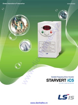
- 1. Variable Frequency Drive / Inverter 0.4-2.2kW 1 phase 200-230Volts iC5 www.dienhathe.xyz www.dienhathe.vn
- 3. �� Modbus communication (Option) �� PID control �� Sensorless vector control �� Motor parameter auto tuning MMooddeellss 0055 WWiirriinngg 0077 KKeeyyppaadd 0088 TTiippss oonn IInnssttaallllaattiioonn 1188 PPrrooggrraamm ppaarraammeetteerrss ddeessccrriippttiioonnss 1111 0044 FFeeaattuurreess 0066 SSppeecciiffiiccaattiioonnss 0088 TTeerrmmiinnaall ccoonnffiigguurraattiioonn 0099 PPrrooggrraamm PPaarraammeetteerrss 1166 CChheecckkiinngg && TTrroouubblleesshhoooottiinngg “ Global standard iC5, serves a wide variety of applications to meet the majority of user needs. ” www.dienhathe.xyz www.dienhathe.vn
- 4. “ Compact iC5, is the best for a small and cost effective configuration” “ Compact iC5, is the best for a small and cost effective configuration” www.dienhathe.xyz www.dienhathe.vn
- 5. 04 FFeeaattuurreess Sensorlessvectorcontrol The iC5 adopts sensorless vector control algorithm, and it improves not only the torque control characteristics, but the speed controlability in an uncertain condition caused by the load variation as well. Autotuning The auto tuning algorithm in the iC5 sets the motor factors automatically that brings the traditional commissioning difficulties mainly in low speed by the load variation and the low torque generation to a settlement. PNPandNPNswitchabledualsignals The iC5 provides PNP and NPN signals for outside controllers. It works with 24Vdc regardless of the type of PLC or control signals. Communicationinterface,ModBus-RTU The iC5 provides the most popular communication interface, ModBus-RTU for remote control by PLC or other devices. ProgrammablePIDprocesscontrol PID process control is used in iC5 to make speed corrections quickly with a minimal amount of overshoot and oscillation for the control of flow, temperature, pressure and etc. ��Difficulty of measuring the motor constant��Input errors by an user ��Low torque in low speed ��Low speed by the load variation ��Setup by an expert �� Setup by an user �� Improving torque in low speed �� Auto tuning of the motor characteristics�� Optimized motor control �� LS Inverter iC5 Series characteristic www.dienhathe.xyz www.dienhathe.vn
- 6. Modelno.ofLSStarvertdrive Input : voltage, current, frequency and phase Output : voltage,current,capacity(FLA),frequencyandphase BarcodeandSerialno. INPUT 200 ~ 230V 1phase 5.5A 50/60Hz OUTPUT 0 ~ INPUT V 3phase 2.5A 0.1~400Hz 0.5HP/0.4kW 05 MMooddeellss Applicablemotor 0.4kW(0.5HP) 0.75kW(1HP) 1.5kW(2HP) 2.2kW(3HP) EMIfilteroptional Inputvoltage LSStarvertdrive Motorrating (004:0.4kW~022:2.2kW) NameofSeries SV004iC5-1 SV008iC5-1 SV015iC5-1 SV022iC5-1 220V, single phase www.dienhathe.xyz www.dienhathe.vn
- 7. 06 SSppeecciiffiiccaattiioonnss ��Specifications(200-230Vclass) Model SV004iC5-1 SV008iC5-1 SV015iC5-1 SV022iC5-1 Motor rating [HP] 0.5 1 2 3 [kW] 0.4 0.75 1.5 2.2 Output ratings Capacity[kVA] 0.95 1.9 3 4.5 FLA[A] 2.5 5 8 12 Voltage Threephase,200to230V Frequency 0to400Hz Input ratings Voltage Singlephase,200to230V( ±10%) Frequency 50to60Hz( ±5%) ��Control Control method V/Fcontrol,Sensorlessvectorcontrol Frequency setting resolution ∙Digitalreference : 0.01Hz ∙Analogreference : 0.06Hz/60Hz Frequency setting accuracy ∙Digital : 0.01%ofMaximumoutputfrequency ∙Analog : 0.1%ofMaximumoutputfrequency V/F ratio Linear,Squarpattern,UserV/F Overload capacity 1min.at150%,30sec.at200%(withinversecharacteristic) Torque boost Manual(0to15%adjustable),Auto �� Operation Input signal Operator control Keypad/Terminal/Communications Frequency setting ∙Analog:0~10V/4~20mA ∙Digital:Keypad ∙Communication:RS485 Start signal Forward/Reverse Multi-step Settingupto8speeds(usemulti-functionterminal) Multi-step accel 0.1~6000sec.Max.8typesavailablebymulti-functionterminal /decel time Selectableaccel/decelpatterns:Linear,UandS Emergency stop Interruptingtheoutputofthedrive Jog Jogoperation Fault reset Resetthefaultwhenprotectivefunctionisactive Output signal Operation status & Frequencydetection,Overloadalarm,Stalling,Overvoltage,Undervoltage, Fault output Driveoverheating,Run,Stop,Constantspeed,Speedsearching, Faultoutput(RelayandOpencollectoroutput) Indicator Chooseonefromoutputfrequency,current,voltageandDCvoltage.(Outputvoltage:0~10V) Operation DCbraking,Frequencylimit,Frequencyjump,Secondfunction, function Slipcompensation,Reversingprevention,Autorestart,PIDcontrol ��Protectionfunctions Drive trip Overvoltage,Undervoltage,Overcurrent,Driveovertemperature,Motorovertemperature,I/Ophaseloss,I/Omis-wiring, Overload,Externaldevicefault1.2,Lossofspeedcommand,Hardwarefault, Communicationerror,CPUerror Drive alarm Stallprevention,Overloadalarm Momentary ∙∙Lessthan15msec:keepingoperation power less ∙∙Morethan15msec:autorestartavailable �� Displaykeypad Operation information Outputfrequency,currentandvoltage,Setfrequencyvalue,Operationspeed,DCvoltage Trip information Displaythetripcausewhentheprotectionfunctionactivates. Recent5faultsrecordsstored �� Environment Operating ambient temp. -10℃ ~50℃ Storage temperature -20℃ ~65℃ Humidity 90%Rhmax.(noncondensing) Altitude & Vibration 1000mmax, 5.9m/sec2 (0.6g)max. Atmosphere Nocorrosivegas,flammablegas,oilmistordust Pressure 70~106k Pa www.dienhathe.xyz www.dienhathe.vn
- 8. 07 WWiirriinngg short-circuitlink (* reserved for DC reactor) ACinput Singlephase 200 ~ 230V Ground KNOB Multi-function Inputterminal Analogoutput (0~10V) PNP DC24V output (factory set : Forward) Multi-functioninputterminals,P1toP5 (factory set : Reverse) (factory set : Emergency stop) (factory set : RST) (factory set : JOG) Multi-functionrelay outputterminal Multi-functionopencollector outputterminal Power for speed signal (12V 10mA) Speed signal input (0~10V) Speed signal input (4~20mA) Common P L1 U V IM AM W AM CM 30A 30B 30C MO EXTG L2 G P1 P2 P3 P4 P5 P24 VR VI I CM MCCB P1 N Note : 1.●●= Main circuit terminal ○○= Control circuit terminal 2. Analog output voltage is adjustable upto 12V. 3. Speed command can be set by Voltage, Current, Voltage+Current, Keypad, Keypad knob+Voltage , and Keypad knob+current. www.dienhathe.xyz www.dienhathe.vn
- 9. 08 TTeerrmmiinnaall ccoonnffiigguurraattiioonn KKeeyyppaadd LL11 LL22 PP PP11 NN UU VV WW GG 3300AA 3300BB 3300CC MMOO EEXXTTGG PP2244 PP11 PP22 CCMM PP33 PP44 PP55 VVRR VV11 CCMM II AAMM Key Function Description RUN Runkey Tooperatethedrive STOP/RESET Stop/Resetkey Tostopoperatingorresetincaseoffault ●● Program/Enter Tochangeparametersandsavethem KNOB(Volume) Frequency Tochangethefrequency NPN/PNP Selection ModeselectionbetweenNPNandPNP ▲▲ Up Toincreasetheparametervalues ▼▼ Down Todecreasetheparametervalues ◀◀ Left Tomovethecursorleft ▶▶ Right Tomovethecursorright Terminal Signal Description L1, L2 AClineinput SinglephaseAClineinput U, V, W Driveoutput 3phaseoutputterminalstomotor P, P1 DCreactor ConnectingDCreactor G Ground Chassisground Terminal Signal Description Input P1, P2 Multi-functioninput Usedformulti-functioninput.Factorydefaultsettingsareasfollows. P1=FX,Forward P3, P4, P5 P2=RX,Reverse P3=BX,Emergencystop P4=RST,Faultreset P5=JOG,JogOperationCommand P24 PNPDC24Voutput DC24Vpowersupplyincaseof PNPmode VR Frequencysettingpower PowerforAnalogfrequencysetting, Maximumoutputis+12V10mA VI Frequencysetting(Voltage) InputDC0to10Vtosetfrequency.Inputresistanceis20kΩ I Frequencysetting(Current) InputDC4to20mAtosetfrequency.Inputresistanceis250Ω CM Common CommonterminalfortheanalogfrequencysettingsignalandtheFM(formonitoring) Output AM-CM Formonitoring OutputoneoutofOutputfrequency,Outputcurrent,OutputvoltageandDCvoltage. FactorydefaultsetistoOutputfrequency. Maximumoutputvoltage=0to12V,outputcurrent=10mA 330A, 30C Multi-functionrelayand Tointerrupttheoutputwhentheprotectionfunctionactivates 30B Opencollectoroutput oroutputmulti-functionsignal. MO-EXTG Terminal Multi-functionrelayterminal:Max.AC250V/1A,DC30V/1A Opencollectoroutputterminal:Max.DC24V50mA www.dienhathe.xyz www.dienhathe.vn
- 10. 09 PPrrooggrraamm ppaarraammeetteerrss �� Parametergroup �� Parametergroupnavigation There are 4 parameter groups to set parameters properly for the operation. ●● Shifting between groups is possible only in the first code of each group. (1) The value of the Command frequency will be displayed in the first code of the Drive group. It will show the value set by the operator. The factory set value is 0.0. ShiftbyusingRightshiftkey(▶▶) ShiftbyusingLeftshiftkey(◀◀) Drive group Basic operation parameters such as Command frequency, Accel/Deceltime,etc. Function 1 group BasicfunctionalparametersforadjustingOutputfrequency, Voltage,etc. Function 2 group ApplicationparametersofPIDoperation,The2ndmotor setting,etc. Input/Output group ParameterstoconstructthesequencesuchasMulti-function terminalsetting,etc DRV Gr. FU1 Gr. FU2 Gr. I/O Gr. (1) (1) Group Description Drive group BasicparameterssuchasCommandfrequency,Accel/Deceltime,etc. Function 1 group BasicfunctionalparameterssuchasMax.frequency,Torqueboost,etc. Function 2 group ApplicationparameterssuchasFrequencyjump,Max./Min.oflimitoffrequency,etc. Input/Output group ParameterstoconstructthesequencesuchasMulti-functionterminalsetting,Autooperation,etc. www.dienhathe.xyz www.dienhathe.vn
- 11. 10 PPrrooggrraamm ppaarraammeetteerrss �� ParameternavigationinDrivegroup �� ProceduretosetcommandfrequencyinDrivegroup To input new command frequency 30.05[Hz] from 0.0 set in the factory 1 ∙∙The first code “0.0” displayed. ∙∙Press up(▲▲) key once to move to next code. ∙∙The second code “ACC” appears. ∙∙Press up(▲▲) key once to move to next code. ∙∙The third code “dEC” is shown. ∙∙Press up(▲▲) key to move to next code. ∙∙To move to the last code press up(▲▲) key until “drC” appears. ∙∙Press up(▲▲) key once more to return to the first code. ∙∙To move in reverse order use down(▼▼) key. 2 3 5 1 2 3 5 6 7 8 9 4 4 ∙∙The first code “0.0” displayed. ∙∙Press pro/ent(●●) key. ∙∙The digit of the first decimal place can be changed. ∙∙Press right (▶▶) key. ∙∙The digit of the second decimal place can be changed. ∙∙Press up(▲▲) key until the digit becomes 5. ∙∙Press left(◀◀) key. ∙∙The left digit can be set. ∙∙Press left(◀◀) key. ∙∙Press left(◀◀) key. ∙∙Though 00.0 is displayed, the actual value remains at 0.05. ∙∙Make 3 by pressing up(▲▲) key. ∙∙Press pro/ent(●●) key. ∙∙30.0 is flickering. ∙∙Press pro/ent(●●) key to stop the flickering. ∙∙Command frequency 30.0 is stored. Note : (1) The LCD on the keypad of Drive iC5 displays only 3 digits. Use the shift keys (◀◀ ▶▶) to monitor and set the parameters. (2) To cancel the parameter setting press the shift keys (◀◀ or ▶▶) while 30.0 is flickering in the procedure no. 8 . www.dienhathe.xyz www.dienhathe.vn
- 12. 11 PPrrooggrraamm ppaarraammeetteerrss ddeessccrriippttiioonnss Description Setting range Factory default Adjustable during run Keypad display 0.00 Outputfrequency:duringrun 0toMax.frequency[Hz] 0.00 Yes Referencefrequency:duringstop ACC Accelerationtime 0to6000[sec] 5 Yes DEC Decelerationtime 0to6000[sec] 10 Yes 0(Keypad) Drv Drivemode 1(Fx/Rx-1) 1 No 2(Fx/Rx-2) 3(ModBus) 0(Keypad-1) 1(Keypad-2) 2(Volume) 3(V1) Frq Frequencymode 4(I) 0 No 5(Volume+1) 6(V1+I) 7(Volume+V1) 8(ModBus) St1 Stepfrequency1 0toMax.frequency[Hz] 10.00 Yes St2 Stepfrequency2 0toMax.frequency[Hz] 20.00 Yes St3 Stepfrequency3 0toMax.frequency[Hz] 30.00 Yes Cur Outputcurrent *[A] * * RPM Motorspeed *[rpm] * * DCL DCvoltage *[V] * * v0L/P0r/t0r Userdisplayselection * * * n0n Faultdisplay * * * drC Motordirectionset F(Forward) F Yes R(Reverse) FU1 FunctionGroup1selection * Yes FU2 FunctionGroup2selection * Yes I/O I/OGroupselection * Yes F0 Jumptodesiredcode# 1to60 1 Yes 0(None) F3 Runprevention 1(Forwarddisable) 0 No 2(Reversedisable) F5 Accelerationpattern 0(Linear) 0 No 1(S-curve) F6 Decelerationpattern 0(Linear) 0 No 1(S-curve) 0(Decel) F7 Stopmode 1(Dc-brake) 0 No 2(Free-run) F8 DCinjectionbrakingfrequency F23to60[Hz] 5 No F9 DCinjectionbrakingON-delay 0to60[sec] 0.1 No F10 DCinjectionbrakingvoltage 0to200[%] 50 No F11 DCinjectionbrakingtime 0to60[sec] 1 No F12 StartingDCinjectionbrakingvoltage 0to200[%] 50 No F13 StartingDCinjectionbrakingtime 0to60[sec] 0 No F14 Motorexcitingtime 0to60[sec] 1 No F20 Jogfrequency 0to400[Hz] 10 No F21 Maximumfrequency 40to400[Hz] 60 No F22 Basefrequency 30toMax.frequency[Hz] 60 No F23 Startingfrequency 0to10[Hz] 0.5 No F24 Frequencylimitselection 0(No),1(Yes) 0 No F25 Frequencylimit-high 0toHighlimit[Hz] 60 No F26 Frequencylimit-low LowlimittoMax.frequency[Hz] 0.5 No F27 Manual/Autotorqueboostselection 0(Manual),1(Auto) 0 No F28 Torqueboostinforwarddirection 0.0to15.0[%] 5 No F29 Torqueboostinreversedirection 0.0to15.0[%] 5 No 0(Linear) F30 Volts/Hzpattern 1(Square) 0 No 2(UserV/F) Drive group FU1 group www.dienhathe.xyz www.dienhathe.vn
- 13. 12 PPrrooggrraamm ppaarraammeetteerrss ddeessccrriippttiioonnss Description Setting range Factory default Adjustable during run Keypad display F31 UserV/F-frequency1 0toF33[Hz] 15 No F32 UserV/F-voltage1 0to100[%] 25 No F33 UserV/F-frequency2 F31toF35[Hz] 30 No F34 UserV/F-voltage2 0to100[%] 50 No F35 UserV/F-frequency3 F33toF37[Hz] 45 No F36 UserV/F-voltage3 0to100[%] 75 No F37 UserV/F-frequency4 F35toMaximumfrequency[Hz] 60 No F38 UserV/F-voltage4 0to100[%] 100 No F39 Outputvoltageadjustment 40.0to110.0[%] 100 No F40 Energysave 0to30[%] 0 Yes F50 Electronicthermalselection 0(No),1(Yes) 0 Yes F51 Electronicthermallevel-1min. F52to200[%] 150 Yes F52 Electronicthermallevel-continuous 50toF51[%] 100 Yes F53 Motorcoolingsystem 0(selfcool) 0 Yes 1(forcedcool) F54 Overloadalarmlevel 30to150[%] 150 Yes F55 Overloadalarmholdtime 0to30[sec] 10 Yes F56 Overloadtripselection 0(No),1(Yes) 1 Yes F57 Overloadtriplevel 30to200[%] 180 Yes F58 Overloadtripdelaytime 0to60[sec] 60 Yes 000to111(bitset) F59 Stallpreventionmodeselection Bit0:Duringaccel. 000 No Bit1:Duringsteadyspeed Bit2:Duringdecel. F60 Stallpreventionlevel 30to150[%] 150 No H0 Jumptodesiredcode# 1to95 1 Yes H1 Previousfaulthistory1 nOn * H2 Previousfaulthistory2 nOn * H3 Previousfaulthistory3 nOn * H4 Previousfaulthistory4 nOn * H5 Previousfaulthistory5 nOn * H6 Deletefaulthistory 0(No),1(Yes) 0 Yes H7 Dwellfrequency 0toMax.frequency[Hz] 5 No H8 Dwelltime 0to10[sec] 0 No H10 Selectionofjumpfrequency 0(No),1(Yes) 0 No H11 Jumpfrequency1,low 0toH12[Hz] 10 No H12 Jumpfrequency1,high H11toMaximumfrequency[Hz] 15 No H13 Jumpfrequency2,low 0toH14[Hz] 20 No H14 Jumpfrequency2,high H13toMaximumfrequency[Hz] 25 No H15 Jumpfrequency3,low 0toH16[Hz] 30 No H16 Jumpfrequency3,high H15toMaximumfrequency[Hz] 35 No H17 InclinationatthebeginningofScurve 1to100[%] 40 No H18 InclinationattheendofScurve 1to100[%] 40 No H19 Outputphaselossprotection 0(No),1(Yes) 0 Yes H20 PowerONstartselection 0(No),1(Yes) 0 Yes H21 Restartafterfaultreset 0(No),1(Yes) 0 Yes 0000to1111(bitset) Bit0:Duringaccel. H22 Speedsearchselection Bit1:Afterfaultreset 0 No Bit2: Restartedafterinstantpowerfailure Bit3:WhenH20issetto1(Yes) H23 Speedsearchcurrentlimitationlevel 8to200[%] 100 Yes H24 SpeedsearchPgain 0to9999 100 Yes H25 SpeedsearchIgain 0to9999 1000 Yes H26 Numberofautorestartattempt 0to10 0 Yes H27 Delaytimebeforeautorestart 0to60[sec] 1 Yes H30 Motorpowerratingselection 0.2,0.75,1.5,2.2[kW] * No H31 Numberofmotorpoles 2to12 4 No H32 Ratedmotorslip 0to10[Hz] * No H33 RatedmotorcurrentinRMS 0to20[A] * No H34 NoloadmotorcurrentinRMS 0.1to20[A] * No H36 Motorefficiency 70to100[%] * No FU1 group FU2 group www.dienhathe.xyz www.dienhathe.vn
- 14. 13 PPrrooggrraamm ppaarraammeetteerrss ddeessccrriippttiioonnss Description Setting range Factory default Adjustable during run Keypad display H37 Loadinertia 0to2 0 No H39 Carrierfrequency 1to15[kHz] 3.0 Yes 0(V/F) H40 Controlmodeselection 1(Slipcompen) 0 No 2(PID) 3(Sensorlessvectorcontrol) H41 Autotuning 0to1 0 Yes H42 Statorreristance 0to5[ߟ] 0 Yes H44 Leakageinductance 0to300[mH] 0 Yes H45 SensorlessPgain 0to32767 1000 Yes H46 SensorlessIgain 0to32767 100 Yes H50 PIDfeedbacksignalselection 0(I) 0 No 1(V1) H51 PgainforPIDcontrol 0to999.9[%] 300 Yes H52 IgainforPIDcontrol 0.1to32.0[sec] 1 Yes H53 DgainforPIDcontrol 0.1to30.0[sec] 0 Yes H54 FgainforPIDcontrol 0to999.9[%] 0 Yes H55 LimitfrequencyforPIDcontrol 0toMax.frequency[Hz] 60 Yes H70 ReferencefrequencyforAccel/Decel 0(Max.freq.) 0 Yes 1(Deltafreq.) 0(0.001sec) H71 Accel/Deceltimescale 1(0.01sec) 1 No 2(1sec) 0(Commandfrequency) 1(Accel.Time) 2(Decel.Time) 3(Drivemode) 4(Frequencymode) 5(Stepfrequency1) 6(Stepfrequency2) 0 YesH72 PowerOndisplay 7(Stepfrequency3) 8(Current) 9(Speed) 10(DClinkvoltage) 11(Userdisplay) 12(Faultdisplay) 13(Motordirection) 0(Voltage) H73 Userdisplayselection 1(Watt) 0 Yes 2(Torque) H74 Gainformotorspeeddisplay 1to1000[%] 100 Yes H79 Softwareversion x.xx x.xx * H81 2ndaccelerationtime 0to6000[sec] 5 Yes H82 2nddecelerationtime 0to6000[sec] 10 Yes H83 2ndaccelerationtime 30toMax.frequency[Hz] 60 No 0(Linear) H84 2ndV/Fpattern 1(Square) 0 No 2(UserV/F) H85 2ndforwardtorqueboost 0.0to15.0[%] 5 No H86 2ndreversetorqueboost 0.0to15.0[%] 5 No H87 2ndstallpreventionlevel 30to150[%] 150 No H88 2ndelectronicthermallevel-1min. H89to200[%] 150 Yes H89 2ndelectronicthermallevel-continuous 50toH88[%] 100 Yes H90 2ndmotorratedcurrent 0.1to20[A] * No 0(No) 1(Allgroups) H93 Parameterinitializing 2(Drive) 0 No 3(Function1) 4(Function2) 5(I/O) H94 Parameterwritingprotection 0toFFF 0 Yes H95 Parameterchangeprotection 0toFFF 0 Yes FU2 group www.dienhathe.xyz www.dienhathe.vn
- 15. 14 PPrrooggrraamm ppaarraammeetteerrss ddeessccrriippttiioonnss Description Setting range Factory default Adjustable during run Keypad display I0 Jumptodesiredcode# 0to63 1 Yes I1 FilteringtimeconstantforV0signalinput 0to9,999[msec] 10 Yes I2 V0inputminimumvoltage 0to10V 0 Yes I3 FrequencycorrespondingtoI2 0to400[Hz] 0.0 Yes I4 V0inputmaximumvoltage 0to10V 10 Yes I5 FrequencycorrespondingtoI4 0to400[Hz] 60.0 Yes I6 FilteringtimeconstantforV1signalinput 0to9,999[msec] 10 Yes I7 V1inputminimumvoltage 0to10V 0 Yes I8 FrequencycorrespondingtoI7 0toMax.frequency[Hz] 0.0 Yes I9 V1inputmaximumvoltage 0to10V 10 Yes I10 FrequencycorrespondingtoI9 0toMax.frequency[Hz] 60 Yes I11 FilteringtimeconstantforIsignalinput 0to9,999[msec] 10 Yes I12 Iinputminimumcurrent 0to20[mA] 4 Yes I13 FrequencycorrespondingtoI12 0toMax.frequency[Hz] 0 Yes I14 Iinputmaximumcurrent I12to20[mA] 20 Yes I15 FrequencycorrespondingtoI14 0toMax.frequency[Hz] 60.0 Yes 0(None) I16 Criteriaforanalogspeedsignalloss 1(Halfofx1) 0 Yes 2(Belowx1) 0(FX) 1(RX) 2(BX) 3(RST) 4(JOG) 5(Speed-L) 6(Speed-M) 7(Speed-H) 8(XCEL-L) Definitionofmultifunction 9(XCEL-M) I20 inputterminal 10(XCEL-H) 0(FX) Yes P18,9,15,20,21,22,23,24,25,26 11(DC-Brake) (-reserved-) 12(2ndfunction) 15(Up) 16(Down) 17(3wire) 18(EXT-A) 19(EXT-B) 21(Open-loop) 22(Maindrive) 23(Analoghold) 24(XCEL-stop) I21 DefinitionofmultifunctioninputterminalP2 SameasaboveI20 1(RX) Yes I22 DefinitionofmultifunctioninputterminalP3 SameasaboveI20 2(EST) Yes I23 DefinitionofmultifunctioninputterminalP4 SameasaboveI20 3(RST) Yes I24 DefinitionofmultifunctioninputterminalP5 SameasaboveI20 4(JOG) Yes I25 Terminalinputstatus 00000-11111[bit] * * I26 Terminaloutputstatus 00-11[bit] * * I27 Filteringtimeconstantformultifunctioninputterminal 0toMax.frequency[Hz] 15 Yes I30 Stepfrequency4 0toMax.frequency[Hz] 30 Yes I31 Stepfrequency5 0toMax.frequency[Hz] 25 Yes I32 Stepfrequency6 0toMax.frequency[Hz] 20 Yes I33 Stepfrequency7 0toMax.frequency[Hz] 15 Yes I34 Accelerationtime1 0to600[sec] 3 Yes I35 Decelerationtime1 0to600[sec] 3 Yes I36 Accelerationtime2 0to600[sec] 4 Yes I37 Decelerationtime2 0to600[sec] 4 Yes I38 Accelerationtime3 0to600[sec] 5 Yes I39 Decelerationtime3 0to600[sec] 5 Yes I40 Accelerationtime4 0to600[sec] 6 Yes I41 Decelerationtime4 0to600[sec] 6 Yes I42 Accelerationtime5 0to600[sec] 7 Yes I/O group www.dienhathe.xyz www.dienhathe.vn
- 16. 15 PPrrooggrraamm ppaarraammeetteerrss ddeessccrriippttiioonnss Description Setting range Factory default Adjustable during run Keypad display I43 Decelerationtime5 0to600[sec] 7 Yes I44 Accelerationtime6 0to600[sec] 8 Yes I45 Decelerationtime6 0to600[sec] 8 Yes I46 Accelerationtime7 0to600[sec] 9 Yes I47 Decelerationtime7 0to600[sec] 9 Yes 0(Frequency) I50 AMoutput 1(Current) 0 Yes 2(Voltage) 3(DClinkvoltage) I51 AMoutputadjustment 100to200[%] 100 Yes I52 Frequencydetectionlevel 0toMax.frequency[Hz] 30 Yes I53 Frequencydetectionbandwidth 0toMax.frequency[Hz] 10 Yes 0(FDT-1) 1(FDT-2) 2(FDT-3) 3(FDT-4) 4(FDT-5) 5(OL) 6(IOL) 7(Stall) I54 Definitionofmultifunction 8(OV) 12 Yes outputterminalMO 9(LV) 10(OH) 11(Lostcommand) 12(Run) 13(Stop) 14(Steady) 15(Search) 16(Ready) 17(Faultselect) I55 Definitionofrelayfunctions SameasaboveI54 17 Yes 000to111(bitset) I56 Faultrelaysetting Bit0:Lowvoltage 010 Yes (30A,30B,30C) Bit1:Trip Bit2:Numberofautoretry I60 Inverternumber 1to32 1 Yes 0(1200bps) 1(2400bps) I61 Baudrate 2(4800bps) 3 Yes 3(9600bps) 4(19200bps) 0(None) I62 Operatingselectionatlossoffreq.reference 1(Freerun) 0 Yes 2(Stop) I63 Waitingtimeafterlossoffreq.reference 0.1to12[sec] 1.0 Yes I/O group www.dienhathe.xyz www.dienhathe.vn
- 17. 16 CChheecckkiinngg && TTrroouubblleesshhoooottiinngg Display Fault/Error Overcurrent Outputcurrenthasbeengreaterthan200%oftheratedcurrent.Theinverteroutputisinterrupted. Description Ground fault Groundfaulthasbeenoccurredattheloadsideoftheinverter.Theinverteroutputisinterrupted. Inverter overload Outputcurrentgreaterthan150%oftheratedcurrenthasbeenflowedover1min. Theinverteroutputisinterrupted. Overload trip Outputcurrenthasbeengreaterthanthesetvalue(F57)oftheratedcurrent. Theinverteroutputisinterrupted. Coolingpin overheat Coolingpinhasbeenoverheatedduetohighambienttemperature. Theinverteroutputisinterrupted. DC link condenser overload IftheDCcondenserofInverterisinneedofreplacementtheinverteroutputisinterrupted. Output phase loss OneormoreofoutputlineU,VandWlost. Theinverteroutputisinterrupted. Overvoltage Theinvertermainvoltagehasbeenrisenabovethepermissiblelimit400V. Checkifdecelerationtimehasbeensettooshortorlineinputvoltageistoohigh. Undervoltage Theinverteroutputisinterrupted. Electronic thermal Theinverteroutputisinterruptedaccordingtothesettime-inversecurvetopreventthe overtemperatureofthemotorduetooverloads. Parameter store error Errorhasbeenoccurredonthestoringofthechangedparameters. Itisdisplayedwhenpowerison. Hardware error Itisdisplayedincaseofsoftwareerror. ItisnotpossibletoresetbySTOP/RSTkeyonthekeypadorresetterminals. Opentheinverterpowerandmakesurethekeypadpowerisoffandclosethepoweragain. Communication error Communicationerrorbetweencontrollerandkeypad. ItisnotpossibletoresetbySTOP/RSTkeyonthekeypadorresetterminals. Opentheinverterpowerandmakesurethekeypadpowerisoffandclosethepoweragain. Coolingfan error Errorhasbeenoccurredonthecoolingfan. Output instant interrupting TheinverteroutputisinterruptedinthecasethatBXterminalisON. Warning:TorestartthedrivemakeBXterminalOFFduringtheFX/RXisON. A contact fault signal input If I20/21/22/23/24setto18isON,theinverteroutputisinterrupted. B contact fault signal input If I20/21/22/23/24setto19isON,theinverteroutputisinterrupted. Frequency command loss Ifsignalinputisfailedforthedrivingbyusinganaloginputoroption(RS485),trytodriveaccordingto thesettingatI62. WWaarrnniinngg :: Ifprotectionfunctionactivatesduetoerror/faultintheinverter,corresponding alarmisdisplayedonthekeypadasshownbelow. Correcttheerror/faultbeforerestartingoritmaydecreasetheinverter’slife expectancy.www.dienhathe.xyz www.dienhathe.vn
- 18. 17 CChheecckkiinngg && TTrroouubblleesshhoooottiinngg Fault/Error Possibslecause ● Accel/Decel time is not enough for the load inertia ▶ Replace the inverter with a higher rating (GD2 ) Increase the Accel/Decel time ▶Operateafterthemotorstopsorusespeedsearch(H22)inFU2 ● The load is greater than the rating of the inverter. in the output terminals. ● Inverter output is assigned during the free run of the motor. ▶ Verify the output wiring ● The motor brake operates too fast. ▶ Verify the mechanical brake. ● Ground fault at the load side of the inverter. ▶ Check to see if there is something wrong with output wiring. ● Insulation of the motor is broken. ▶ Replace a motor. ● The load is greater than the rating of the inverter. ▶ Increase the ratings of a motor and an inverter. ● Power rating is set to the lower value than the load ▶ Check to see if the setting is correct. ● Torque boost is too great. ▶ Reduce the torque boost. ● Fault in the cooling system. ▶ Check to see if there is any alien substance in the ventilation ● The cooling fan is used beyond the life expectancy. system. ● High ambient temperature ▶ Replace the cooling fan. ▶ Keep the ambient temperature below 40°…. ● Fault in the load side contactor ▶ Replace the contactor. ● Wiring problem ▶ Verify the output wiring ● Alien substances are in the ventilator. ▶ Check to see if there is any alien substance in the ● The cooling fan is used beyond the expectancy. ventilation system. ▶ Replace the cooling fan. ● Decel time is not enough for the load inertia(GD2 ) ▶ Increase the Decel time ● There is a survived load in the load side. ▶ Uase DB unit. ● Higher voltage than rating is supplied. ▶ Verify the power voltage. ● Lower voltage than rating is supplied. ▶ Verify the power voltage. ● Power capacity is not enough for the additional ▶ Increase the power capacity. loads like welders and direct-on-line starting motors. ▶ Replace the contactor. ● Fault in the line side contactor ● Overtemperature of the motor ▶ Reduce the load or operation times. ● The load is greater than the rating of the inverter. ▶ Increase the ratings of the inverter. ● Electronic thermal level is set lower than rating. ▶ Adjust the electronic thermal properly. ● Inverter power rating is set to the lower value than the load ▶ Adjust the inverter rating properly. ● Long operation at low speed. ▶ Replace the motor with the separated power cable for the cooling fan. ● The terminal I20/21/22/23/24 set to18/19 is ON Verify the circuits connected to the external fault terminals. ● Frequency command loss at terminals V1 and I Verify the wiring connected to V1 and I terminals. ● Refer to LS or distributors Overcurrent Solution Ground fault Inverter overload Overload trip Cooling fan overheat Output phase loss Coolingfan error Overvoltage Undervoltage Electronic thermal A contact fault signal input B contact fault signal input Frequency command loss Parameter store error Output instant interrupting Communication error www.dienhathe.xyz www.dienhathe.vn
- 19. 18 TTiippss oonn IInnssttaallllaattiioonn M Vector Motor Control Ib’erica (VMC) C/Mar del Carib, 10 - Pol. Ind. La Torre del Rector 08130 - Santa Perp`etua de Mogoda (Barcelona) - SPAIN Tel: (+34) 935 748 206 - Fax: (+34) 935 748 248 e-mail: info@vmc.es - www.vmc.es POWER LINE FILTERS VARIABLE SPEED DRIVES OUTPUT LC FILTERS ※※ Filter for use of LS Inverters : WWaarrnniinngg :: Carefullyreadtheinstructionforinstallationandwiringofinvertersandrelevant devices. Normaloperationisimpossibleincaseoftheimpropersystemdesign andwiring.Thesecanshortenthelifeoftheinverteranddamageitattheworst. INDUCTORS FOR VARIABLE SPEED DRIVES The inductors manufactured with special magneticcores are advisable for location: BETWEEN MAINS AND VARIABLE SPEED DRIVE, in order to protect the equipment from overvoltages, voltage surges and also to limit the line current and the harmonics generated by VSD. BETWEEN VARIBLE SPEED DRIVE AND MOTOR, to absorb the voltage peaks in the motor terminals, when the connection cables are long or there are more than one motor in parallel, for having a better efficiency and to eliminate the humming noise of the motor. The family of filters manufactured by LIFASA has been specially developed and approved for its application with variable speed drives, to assure the compliance of the EMC (Electro Magnetic Compatibility) and the LV safety European Directives, in both industrial and domestic environments. ��Powers from 0.37 to 375 kW ��Sngle/three phase voltages 220/230 Vac ��Three phase voltages 380/460 Vac ��Sensorless vector control, V/F closed loop ��Removable console with copy function ��RS485 communication facilities as standard ��Autotuning ��Special parameters for special applications The commutation of the IGBT's at high frequency (PWM) provokes an output voltage with peaks up to 1300 V The LC filter - low pass - reduce the dV/dt converting the voltage in a sinus waveform, eliminating all the isolation problems in the motor and the emission of interference from the cables. www.dienhathe.xyz www.dienhathe.vn
- 20. www.lsis.bizⓒ 2003.2 LSIS Co.,Ltd. All rights reserved. Specifications in this catalog are subject to change without notice due to continuous product development and improvement. � HEAD OFFICE LS Tower 1026-6, Hogye-dong, Dongan-gu, Anyang-si, Gyeonggi-do 431-848, Korea � Middle East +82-2-2034-4901 / bonseongk@lsis.biz � Europe & Africa +82-2-2034-4376 / ywsohn@lsis.biz � Asia Pacific +82-2-2034-4645 / sungkyup@lsis.biz 2011. 04 Starvert iC5 (E) 2003. 2/(13) 2011. 04 Printed in Korea STAFF �LSIS (Middle East) FZE ��Dubai, U.A.E. Address: LOB 19 JAFZA VIEW TOWER Room 205, Jebel Ali Freezone P.O. Box 114216, Dubai, United Arab Emirates Tel: 971-4-886 5360 Fax: 971-4-886-5361 e-mail: jungyongl@lsis.biz �Dalian LSIS Co., Ltd. ��Dalian, China Address: No.15, Liaohexi 3-Road, Economic and Technical Development zone, Dalian 116600, China Tel: 86-411-8273-7777 Fax: 86-411-8730-7560 e-mail: lixk@lsis.com.cn �LSIS (Wuxi) Co., Ltd. ��Wuxi, China Address: 102-A , National High & New Tech Industrial Development Area, Wuxi, Jiangsu, 214028, P.R.China Tel: 86-510-8534-6666 Fax: 86-510-522-4078 e-mail: xuhg@lsis.com.cn �LSIS-VINA Co., Ltd. ��Hanoi, Vietnam Address: Nguyen Khe - Dong Anh - Ha Noi - Viet Nam Tel: 84-4-882-0222 Fax: 84-4-882-0220 e-mail: srjo@lsisvina.com �LSIS-VINA Co., Ltd. ��Hochiminh , Vietnam Address: 41 Nguyen Thi Minh Khai Str. Yoco Bldg 4th Floor, Hochiminh City, Vietnam Tel: 84-8-3822-7941 Fax: 84-8-3822-7942 e-mail: sbpark@lsisvina.com �LSIS Tokyo Office ��Tokyo, Japan Address : 16th, Higashi-Kan, Akasaka Twin Tower, 2-17-22, Akasaka, Minato-ku, Tokyo, Japan Tel: 81-3-3582-9128 Fax: 81-3-3582-2667 e-mail: jschuna@lsis.biz �LSIS Shanghai Office ��Shanghai, China Address: Room E-G, 12th Floor Huamin Empire Plaza, No.726, West Yan'an Road Shanghai 200050, P.R. China Tel: 86-21-5237-9977 (609) Fax: 89-21-5237-7191 e-mail: jinhk@lsis.com.cn �LSIS Beijing Office ��Beijing, China Address: B-Tower 17FL.Beijing Global Trade Center B/D. No.36, BeiSanHuanDong-Lu, DongCheng-District, Beijing 100013, P.R. China Tel: 86-10-5825-6025,7 Fax: 86-10-5825-6026 e-mail: cuixiaorong@lsis.com.cn �LSIS Guangzhou Office ��Guangzhou, China Address: Room 1403,14F,New Poly Tower,2 Zhongshan Liu Road,Guangzhou, P.R. China Tel: 86-20-8326-6764 Fax: 86-20-8326-6287 e-mail: linsz@lsis.biz �LSIS Chengdu Office ��Chengdu, China Address: Room 1701 17Floor, huanminhanjun internationnal Building, No1 Fuxing Road Chengdu, 610041, P.R. China Tel: 86-28-8670-3101 Fax: 86-28-8670-3203 e-mail: yangcf@lsis.com.cn �LSIS Qingdao Office ��Qingdao, China Address: 7B40,Haixin Guangchang Shenye Building B, No.9, Shandong Road Qingdao 26600, P.R. China Tel: 86-532-8501-6568 Fax: 86-532-583-3793 e-mail: lirj@lsis.com.cn �� Global Network �� For your safety, please read user's manual thoroughly before operating. �� Contact the nearest authorized service facility for examination, repair, or adjustment. �� Please contact a qualified service technician when you need maintenance. Do not disassemble or repair by yourself! �� Any maintenance and inspection shall be performed by the personnel having expertise concerned.Safety Instructions www.dienhathe.xyz www.dienhathe.vn