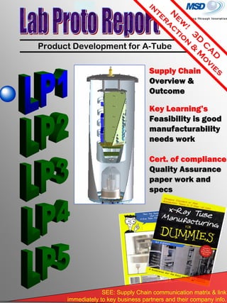
SlideShare a Scribd company logo
1 of 34
Download to read offline
pg 1
N
ew
!
3D
C
A
D
in
teraction
&
M
ovies
Product Development for A-Tube
Supply ChainSupply Chain
Overview &Overview &
OutcomeOutcome
Key LearningKey Learning’’ss
Feasibility is goodFeasibility is good
manufacturabilitymanufacturability
needs workneeds work
SEE: Supply Chain communication matrix & link
immediately to key business partners and their company info.
Cert. of complianceCert. of compliance
Quality AssuranceQuality Assurance
paper work andpaper work and
specsspecs
pg 2
Table of Contents
Technical Glass
Altair TechnologyLarson Glass
Garland Precision
Agilent
Lower Level
Material
Material
Transformation &
Assembly Integration
SANDT
Applied Physics
11
20
23
5
Thin Film Tech
pg 3
Introduction
LP1 (Lab Proto #1) Retrospective
Purpose:
System Requirements:
Navigation:
Audience:
This is a multi-purpose document and meant to be read at different levels of details based on
the audience.
• COMMUNICATE – There have been a lot of queries regarding the status of this project and
the lab units. Hopefully this will answer those as well as detail out the key learning's, progress
and next steps in development.
• CENTRALIZE – This is also intended as a starting point for production documentation. This
pulls together a lot of separate documents & details across the entire supply chain.
• COODINATE – A lot of effort has been made to facilitate communication between Agilent and
the vendors. Moving forward, these efforts need to increase as we turn over deliverables to
manufacturing, the supply chain changes, and improvements are implemented.
This is a broad base distribution. All participants are requested to give feed back either within
the adobe editor or off-line to myself.
• DEVELOPMENT ENGINEERS – This document is an archive of development and learning
across all the LP units. May this serve as a central point of reference as resources change.
• MANAGMENT – Management changes throughout the organization require that they come up
to speed on the project at different levels. This will serve as both a status updates and business
impact capture.
• SUPPLY CHAIN PARTNERS – All S.C. members are under NDA (non-disclosure
agreements) and though this is primarily an Agilent documentation, I want to include them for
feedback and coordinated efforts moving forward.
The document is designed to be able to navigate to the desired information and level of detail
required for the reader with ease.
• PDF ONLY – Read and / or Print as a PDF only
• Bookmarks – click the bookmarks icon to navigate by root tree external to the document
• Links – There are a lot of links within the text and pictures to direct the reader to associated or
detailed information.
• Comments – click the comment icon to read inserted comments of others or the reader
toolbar icon to inset comments of your own.
You should be prompted to free upgrade to the appropriate web site for the application you are
attempting to use. For full use of this document I recommend Flash 8.0, Adobe reader 8.1,
Microsoft media and/or real player and associated graphic card to support these.
pg 4
Executive Summery
Supplier Part Process Learning's Improvements
Tech Glass Chemical prep Toluene by itself devitrifies on the glass
Use 3 chem. in order: Toluene,
Acetone, IPA
Thin Film QA data Need to acquire along with the parts
Crystal Vogel
mount
Mechanical design more robust than
preliminary tests revealed
Work with vendor to collect data and
improve design.
Adding Getter to LP2 & LP5
Adding vented ceramic to LP2 & LP5
Bending pins to mate header induced
unnecessary strain
difficult to Spot welding with the legs
interference
Design is rated to withstand only
75PSIG
Production HV process will only subject
the part to 45PSIG
Need to call out flared end . 1.75"
call out of straight wall of glass > 0.1".
Larger diameter glass will be used on
production protos
Will flare edge to minimize ovality &
increase weld / reworkabiliy
Welding
Lost Vacuum integrity at 100C at weld
point
Moving this process to within Tech
Glass
Anode machinist issues on 2 rounds of 5 sets
Adjusted material thickness and
outsourced to another supplier
Cu Pipe
will change to 3/8 dia to increase
manufacurability
Late delivery
set expectations on the front end across
broader audience
Increase communication and OF
involvement to drive deadlines.
Header assembly Add alignment specification to print
Header
assembly
Add additional leak check points to
discern of failure is process or material.
Old Mini Task pump was insufficient for
process
replaced with new unit & added gate
valve
Data transfer from NT 4.0 painful
Migrated RGA software to IRP
computer
Move process to Tech glass Qualify
with LP5
created fixture to assist in electrical
interface
PS limit was 165kV
Increased to 192kV by eliminating the V
limit
Need to add ON/OFF power cycle
need to purchase 2 cameras that were
removed for customer support
Added Magnification fixture
Need to validate SW /Gui test
need to purchase and install x,y motors
and controllers
Final Test
could not measure spot size indirectly
with Genesis camera's
Agilent
Tech
Bake Out
High voltage
seasoning
KG-400-T-SPCL
Larson
Altair Tech
Mounting cage
New Mount part will have 2 legs (not 4)
and receiving holes are aligned to
correct distances
FTSP-6 (6 pin
header)
AP Tech
Vacuum
integrity
Click Icon (left)
to go to KEY
Learning's LP!
UNIT
Performance
Functionality
Requirement SPECIFICATION P/F
Gun Gun Power perform at <13.5 W
<10uA @175kV
No arcing at 160kV
Grid Dielectric Standoff < 1uA @ 2kV
Anode Voltage 160kV > 10k hrs
100uA >10k hrs
Variance <1%
Vacuum integrity <E-7 Torr for 72 hrs w/o pump
< 60um X-ray spot size
< 5.75 FWHM base image quality not tested
> 5DX (100gs / 5.7 R/min)
Flux variance <2%
Power cycle capibility complete cycle < 2 sec not tested
continious duty cycle Operate at 160kV/100uA (16W) >12k hrs not tested
Upper limits 165kV / 125 uA (20.6 W) not tested
Diagnostics Record operational parameters not tested
Interlocks Comply to all safety regulations not tested
Power Supply
Image quality
Tube
Tube Dielectric Standoff
Beam Current
Flux (signal) output
LP1 (Lab Proto #1) completed Final Test at the end of October. Then a post autopsy
analysis and destructive testing was conducted on key parts to gain data for improving processes
and design. LP1 passed all critical functional test requirements within specification!!! Unfortunately,
it did not hold vacuum long enough to allow for system test or ship to SANDT to work on the power
supply. Below is a quick summery across the three key parts to A-tube
• SUPPLIERS – The S.C. (Supply Chain) staged for Lab Proto build were very cooperative and
helpful through-out the design stages. There were no feasibility, with the exception of SANDT, and
we will continue to partner together through the DFM (design for manufacturability) improvements.
Special thanks to AP for some of their testing and development. I believe the #1 risk we face is
with SANDT power supply. We have yet to receive a working unit and responsiveness is low.
• DESIGN & MATERIAL – There was a significant amount of focus on the tube re-design and QA
(Quality Assurance) measures on key factors that contributed to this success. I believe we have a
sound design based on: design reviews, thermal analysis, Pre-testing, and the data collected
during build & processing. There certainly is a lot of work remaining for safety margins and
potential yield issues in manufacturing.
• PROCESSES – Components, assemblies, and processes were distributed across vendors
associated to their key skill sets. The last three processes were maintained within Agilent for
control and data gathering. RFS (requirements, features, and specifications) are detailed at the
bottom right of each process.
pg 5
Product Description
pg 6
Product Overview
Click to
generate 3D
CAD.
** The primary focus will be on the X-ray Tube
until SANDT provides a working unit.
pg 7
System Upgrade
pg 8
System Integration
Click Pictures
on far right to
play animation
Strategy:
• Utilize fixture tools to align Tube <> Camera Array eliminate the positioning
operation and the operator variables.
• A Tube has a steady state beam position and will eliminate the defection power
supply, the focus power supply, and all the HW, SW, and operations required to
support these.
• F.T. (Final Test) will replicate the system in Image chain & geometry to ensure
quality measurement transportability (Gauge RnR will be conducted in QSO)
TOP
BOTTOM
Alignment tool (N7280-60145) <> Cameral Array:
FRONT (system & FT)
A-Tube (N7280-80009) <> Base plate :
TOP
BOTTOM
Base plate <> Alignment tool (N7280-60145):
pg 9
PHASE I
Proof of Principle
PHASE II
US – Quality Testing
MY – Set up manufacturing
PHASE II
MY – Repeat success in
Production environment
Schedule
ORIGINAL schedule @ Dev Checkpoint (Jul)
• Original LPC (lab proto complete) milestone has moved out 1 month.
• Due to scope & resource changes the overall schedule will be re-worked at the
end of the month.
• Validation of design & processes will eliminate the 1 month iteration buffer.
Outcome is overall schedule net shift to date is 0.
• LPC WBS (work breakdown structure) for scope, schedule, resource remains
unchanged
CHANGES schedule based on LP1 outcomes
LPC milestone is broken into 2 parts each with a separate buffer allocation:
1. TUBE feasibility (design, suppliers, and process) – 4 weeks buffer (complete)
2. Power supply feasibility (design & integration) – 6 weeks buffer (in process)
pg 10
Material & QA Tracking
Gun Anode Integration Process
APTech Altair TechGlass Agilent
RFQ 1-Mar
15-Mar
SO14290 RFQ 29-Mar
SO3792 12-Apr
PO301379 26-Apr
PO306290 10-May
SO3792 24-May
PO311287 7-Jun
21-Jun
LP1-LP4 5-Jul
LP1-good 19-Jul
2-Aug
LP1-good 16-Aug
LP1done 30-Aug
LP2-fail 13-Sep
LP4-fail LP3-good LP1done 27-Sep
LP1,2,4RMA LP3done LP3process 11-Oct
25-Oct
Altair’s late deliver is the
dominating factor in driving the
schedule. > 5months from PO
release awaiting for balance of
order.
1 instance of non-conforming
gun from AP. Returned with
others for repair.
Overall supplier Quality is good.
Still gaining ground on learning
the product & process. More
tooling and design
improvements will be
implemented on PP1-4 units
pg 11
LP1 Supply Chain
Technical Glass
Altair TechnologyLarson Glass
W / Monel /
Cu Target
Threaded
SS Gun
sleeve
Thin Film Technologies
Garland Precision
Precision
machined
OFHC base
Agilent
Lower Level
Material
Material
Transformation
& Assembly Integration
Processing, Integration, & Test
Agilent LVLD
W Plasma sputter
deposition
FTSP-6
BAKE HV season Integrate Final Test
SANDT
System
Applied Physics
Electron
Gun
Assembly
KG-400-T-SPCL
SST
components for
gun assembly
ImprovingAt RISK GOOD
Supplier Status <legend>
Pass Pass Pass /
lost
vacuum
Fail/skip N/A
Move mouse over & click part, supplier, &
process for details
Braze & TIG weld
QA test, integrate, weld,
align, assemble
N7280-
67900
X-ay
Tube
pg 12
Supplier Communication
Matrix
Supplier
WEB Address Contact Position E-mail Phone
Technical Glass,
Inc.
www.techglass.com
15400 E. Batavia
Dr. Aurora, CO
80011
Ron Bihler
Owner, Senior
Eng
rbihler@techglass.com (303)367-8619
Carol Peters
Purchasing
Agent
cpeters@techglass.com (303)367-8619
Larson Electronic
Glass
www.larsonelectronicgl
ass.com
2840 Bay Road
Redwood City, CA
94063
Chuck Kraft Senior Eng gls2mtl@att.net 650-369-6734
Altair Technologies,
Inc.
http://www.Altair
USA.com
980 Hamilton
Avenue Menlo Park,
Ca, 94025
Jerry Walias Sales JerryW@altairusa.com
(650) 508-8700 x
121
Chris
Ferrari
Engineer cferrari@altairusa.com
(650) 508-8700 x
123
Curtis Allen President CurtisA@altairusa.com
(650) 508-8700
x110
Applied Physics
Technologies
http://www.a-p-
tech.com/
1600 NE Miller Street
McMinnville, Oregon
97128 USA
Cory Fast Engineer Cfast@A-P-Tech.com
(503) 434-5550
x207
Florcia
Hamilton
Purchasing
Agent
FHamilton@A-P-Tech.com (503) 434-5550
Kevin
Kagarice
Research
Scientist
KKagarice@A-P-Tech.com (503) 434-5550
William A.
Mackie,
Ph.D
Owner BMackie@A-P-Tech.com (503) 434-5550
Thin Film
Technologies Inc
http://www.thinfilm
technology.com/h
153 Industrial Way
Buellton, CA 93427
Tom Ives President tives@thinfilmtechnology.com (805) 688-4949
Bob Stokes Quality manager bstokes@thinfilmtechnology.com (805) 688-4949
Garland Precision
machining
N.A.
4000 Cordelia Ln
Soquel, CA 95073
Glen Garland Owner garland@cruzio.com (831) 462-1314
SANDT
http://www.sandt.com
.cn/english/e-
p008.htm
No 188, Yanghebang Rd,
Songjiang High Tech
Park Shanghai, China
Jerry Tang President jtang@aerosino.com +86 21 3763 3098
Joyce Lao
Supply chain
mng
+1 949 351 0588
Joyce Lao Sales agent +1 949 351 0588
Jerry Tang Engineering jtang@aerosino.com +86 21 373 3098
Jerry Tang RnD eng liaison jtang@aerosino.com
+86 139 173
11806
Yifang Wei Production Mng +86 21 3763 3088
Hanyun Cai
Regulatory
agent
+86 21 3763 3088
x1201
Agilent Technologies
Inc
http://www.Agilent
.com
900 S taft rd loveland
Colorado 80537 USA
Bee Giak OF Planner bee-gaik_koay@Aglilent.com +6 04 680 2809
Erick Lewark RnD eng Erick_lewark@agilent.com +1 970 679-2975
Eric Miller RnD eng Eric_Miller@Agilet.com +1 970 679 3805
Agilent Technologies
Microwave (Malaysia)
Sdn Bhd (463532-M)
Building 5 Bayan Lepas
Free Industrial
Zone,Penang,11900,
LIM,KOK-
SUNG
Regulatory
agent
kok-sung_lim@agilent.com +60 4 680-7105
shanmugam
Rajamany
Production Mng
shanmugam_rajamany@agilent.
com
+6 04 8197804
RETURN
link
pg 13
Materials & Design
Pin # Scheme
• Outer pins are odd#
• Inner pins are even #
• 2 outer short leads are 5&6
• 2 inner short leads are 1&3
Lead Lengths (in)
pin # outer inner
1 0.500 0.000
2 1.125 3.500
3 0.500 0.000
4 1.125 3.500
5 0.500 3.500
6 1.125 3.500
Filament Gnd
Filament (+)
Getter (+)
Focus V (+)
Mechanical mount
KG-400-T-SPCL --- LP1 PN
KG-400-TF-SPCL – new PN (3)
(8250 glass composition)
Mechanical mount
Performance
FTSP- 6 – Production PN
(7052 glass composition)
Cross Section of
Design improvement
A
B
C
There were 3 areas of design
margin increase.
1 – Overall length of header to
increase dielectric stand-off
capability. This was reduced as
an effect of A (above)
2 – Pin spacing increased to
maximize mechanical strength
along with straight Kovar pins
3 – Future PP units will use a
flared Kovar welding lip to
maintain circularity and ease of
weld and re-work.
There were 3 areas of design margin to be
addressed and one critical failure.
A – I did not call out a spec for the flare
diameter. This was adjusted at Tech Glass but
should be noted on the print to be >1.75” φ.
B – There was some indicator of stress line in
the header. This piece is rated to only withstand
75PSI force, which is the sum difference of the
vacuum + external SF6.
C- The glass OD reduces at a critical failure
point. Subsequent LP units have a spec of >.1”
future designs will leverage larger glass.
Failure Point – Vacuum loss occurred at the
Kovar pin<>glass interface. Future builds will
have more rigorous leak check of this to identify
if the failure is related to assembly or material
1
1After
Before
2
3
Pin-6 Getter not incorporated in LP1
Click link
to see
QA
specs
pg 14
Photo of HfC provided by:
www.hbci.com/~wenonah/new/cryst
als.htm
LP units utilize a 4 leg
design. PP units will
improve with a integrated
2 leg design (shown)
Design & Build
LP1 unit utilized a non-
vent Ceramic. Other LP
units will use improved
design (shown)
Click in box to
activate 3D model.
See tool bar to
activate explode &
rendered views
Enables
slide bar
controller to
explode
assembly
Show
model tree
& views for
additional
control of
parts
RETURN
link
pg 15
The chart to the right is a composite
from 12 units Q.A. test data from AP.
A 2.5σ or 95% CI (confidence interval)
was established for each temperature
range test set. These limits then set
the SPC boundaries for expected
outputs. Gun 20473 test data is
shown as a green triangle and is within
acceptable limits. It did require much
greater power & temperature the
expected During Final Test. Annealing
Temp (1)
limit and Current run-away
Are displayed as limits for K & W
r e s p e c t i v e l y . .
Pretest
Performance
Post Analysis
T vs W
7.70
8.41
9.01
7.12
6.59
1700
1800
1900
2000
2100
2200
2300
2400
2500
6 7 8 9 10 11 12 13 14
Power (W)
Temp(K)
means
QA test data (12 guns)
LP1 test data
95% CI LL
95% CI UL
LP1 performance
Lineofsight
check
Drop test
directions
X
Click link
to see
QA test
data.
Four guns returned from
HWE were extracted and
repaired with new crystals
and a vented Vogel mount at
Applied Physics. These
were then tested for both
t h e r m a l & e m i s s i o n
characterization at specific
t e m p e r a t u r e s ( s e e
performance data below).
LP1 (labproto-1) unit was
built with gun serial # 20473.
Gun Test fixture at A-P Tech.
The gun was re-tested at
A g i l e n t d u r i n g H e a d e r
a s s e m b ly f o r F i l a ment
continuity (12 + 5 Ohms) and
dielectric stand-off capability.
See Material & QA (quality
assurance) tracking p.30 for
more details. At present,
production standardized
testing and equipment are
b e i n g e x p l o r e d .
Annealing Temp U.C.L
Currentrun-awayU.C.L.
(1) Journal of Materials Engineering and Performance Volume 3(2) April 1994
2 Major concerns were
investigated in autopsy:
mechanical durability &
degradation of performance
due to contaminants in tube.
It was suspected that gun
o p e r a t e d a b o v e t h e
annealing temperature of the
b a s e m a t e r i a l w i l l
compromise the strength of
the Vogel mount assembly.
S o a d r o p t e s t w a s
performed along 2 axis
repeatedly at heights up to
8”. The alignment was
checked visually after each
test. No perceptible shifts in
alignment could be detected.
There was some corrosion
present across the Carbon
and crystal back surfaces but
there was no evidence of any
Oxidization, proving the
vacuum integrity was good.
Future guns will be checked
with an optical pyrometer
prior to Final Testing on
s u b s e q u e n t L P u n i t s .
pg 16
Outlook Item
Anode
assembly
Target
assembly
Process & Integrate
Machined Cu, Monel, SST
Purchased 1.33 CFF
Chemical Clean (Cu target ultrasonic in IPA only)
Click link
to see
QA test
data.
Hydrogen Fire
CuSil (35/65) Braze
TIG weld to glass assembly
Machined W & Monel
Provided Cu coated target
Vacuum Fire
Nicusil Braze W<>Monel
Cusiltin Braze Cu <> Monel
Leak Check (E-10 pp torr)
Visual Inspect
N7280-28034
Coated Cu Target
provided by Thin
Film Technologies
Anode
assembly
Target
assembly
Machined Tungsten (W)
& Monel
OFHC 0.5” pipe, SST
base, and 1.33CFF
Part received and
staged July 23rd.
(click e-mail)
Click over selected comments
below to see feedback and
details.
pg 17
T h e m a c h i n i s t
destroyed 1st
set of
material. 2nd
set
delivered had a
surface defect. Not
critical to quality
(CTQ) but does not
a d h e r e t o t h e
surface call out on
the print. .
Performance & Delivery
Future material will be provided
by an alternate supplier. Units allocated for
pp6-9, machined by Devenus in MY, have
been built to print using a thicker wall and
3/8” OFCH pipe. .
D i s t a n c e f r o m
Corona guard O.D.
to Glass I.D. is
CTQ for dielectric
s t a n d - o f f
r e q u i r e m e n t s .
Concentricity of
parts and TRI (total
indicated run-out)
are the contributing factors. LP1 exhibited
breakdown at the point during HV
seasoning indicated above. Future
iterations will call out < 0.1” TIR and
increase the glass O.D. by 0.25”. .
M i n i m u m g l a s s
strain is critical for
vacuum integrity.
This is visually
inspected with a
Polariscope. Strain
is induced by either
forced fits or non-
t e m p e r a t u r e
controlled welds .
.
LP1 exhibited very low
stress by the lack of heavy gradient lines.
Future iterations will be designed with a
flared Kovar to minimize these factors.
LP1 exhibited a
leak at the weld
joint during bake-
Out process. It
was sealed with HV
torr seal which
a l l o w e d i t t o
p r o c e e d b u t
reduced the upper
limit temp to 375 C as a result. LP1 used a
45 degree cut on the pipe which is more
susceptible to strain. Future LP units use a
1” bend radius as shown on LP3.
.
LP1LP3
Material delivery from Altair
has been the leading factor is
schedule slip. The major
d e l a y s a p p e a r t o b e
associated to working with
lower level vendors, quality
issues, and damage of parts
at both machinist and within
Altair. The scope of the
assembly, the value added of
Altair, and the material
requirements have been
reduced to negate these
factors in the future. .
LP1
LP3
LP4,5
LP2
pg 18
Subsidiary of Williams Advanced
Materials
Air Side Vacuum Side
Electron
beam
Vacuum
Side
Air Side
• Monel
• Tungsten (W)
• Copper (Cu)
OFCH grade
(Oxygen Free High
Conductivity – large
crystal >99.99% purity)
Target
PerformancePre-Test
Design Materials
Heat generated from the E-
beam (16W) is imparted
into a region <156 um2 ~
1079 C. Thermal analysis
was consistent with actual
data and performance.
127um Cu
20um W
E- beam
A sample of 10 targets OD were
measured and found they were
19.01mm + .01 <.748” + .0004”>
which was the limit of the
instrument resolution. Surface
finish (8) within spec. Visual
inspect to coating looks good.
Missing the QA documents &
witness samples from T.F.T
Thermal performance and
bonding properties performed
beyond expect levels. Validated
an 8% safety margin with respect
to power density capability. (see
spot size page for more details).
Thermal transfer and heat
dissipation through bulk target
material indicate T on Air side
and Monel ring <70C (min
thermal expansion & induced
stress)
Q cond. Coeff Q exap
W /m*K m/m*Kx10^6
Be 190 11.3
Cu 400 16.5
W 174 4.5
Monel 21.8 13.5
SST 304L 21.4 17.3
R.F. Magnetron sputter PVD
(Physical Vapor Deposition)
of W & Ti with back etching
of Cu substrate.
5DX target ($4K USK)
Garland Precision ©
T.F.T. coated
Altair provided
Anode material
TFT coating $79.00 USD
Cu Substrate $12.75 USD
TOTAL $91.75 USD
The goals of this design are:
1. Replaceable cheap target
2. Greatest thermal transfer (design margin)
3. Green (Be is considered Hazardous Material)
Future supply chain alternatives (possibly AP tech) could
produce this part utilizing CVD process.
***Prices indicated
reflect MOQ of 45
units. PVD is a “lot
charge’ driven cost.
One target
assembly was
destructive tested to
ensure target
survived the brazing
process and
validate coating
capability. A 5/64th Ball Allen wrench was used to
indent the target on the air side in order to induce
mechanical stress on the bond. Minimum delaminating
was observed between the substrate surfaces.
Click link
to see
QA test
data.
pg 19
TestAssemble
Stage Parts
Bend Leads on header
Dry Fit parts (ensure
ring is on prior to weld)
Weld leads
Tighten set screws &
add SST gun sleeve
Validate Filament
continuity 12.5Ω + .5Ω
Validate grid 1kV
standoff with Hi Pot test
Helium Leak check
Check glass strain with
polariscope
Ensure alignment on
lathe to<.005” TIR
Gun Header Assembly
Staged Parts
Align
Bend
leads & fit
Orientate leads
& set screw
Electrical test
Competed
Assembly
Spot weld leads
LP1 unit was assembled in Agilent,
training Tech Glass on critical steps.
LP3 units were assembled at Tech
Glass. AP Tech will be assembling
the header pieces to their guns for
PP units 6-9.
There is some tuning and tooling
to be implemented on future runs.
No feasibility or interference
limitation.
Supply Chain Coverage
RETURN
link
pg 20
Integration
Click icon to
watch movie
clip
Spinning
on lathe
Inserting header w/
purging tool
TestAssemble
Clean & stage parts
Dry Fit & validate
distances
Mount on Lathe and
validate alignment
Integrate header
assembly
Back purge
Check glass strain with
polariscope
Validate Filament
continuity 12.5W + .5W
Helium Leak check
Check alignment through
target hole
Shape Anode assembly
1. Chemical clean with Toluene,
Acetone, and IPA. Let Dry in clean
environment
2. Dry fit went very well. The
alignment tool had to be adjust for
correct spacing of Gun to Anode.
3. Gun alignment appeared to be < 1
degree out. Very Good!
4. There was some divitrification
possibly due to residual Toluene
during shape process. Acetone was
not available and should take care of
this in future runs.
5. The header had to be flared prior to
integration which reduced the overall
height. Larson to provide flare on PP
units.
6. Subsequent runs may investigate
back filling with O2 during cooling to
burn out any surface impurities
7. Alignment post assembly appears
very good (see movie clip)
8. There was some stain apparent on
the glass and header. Nothing critical
and glass will anneal @ 450C
(removing the stress)
9. There was some concern that the
Kovar pin would oxidize and change
the resistance. Did not see this as an
issue
10. He leak check was
performed at Agilent for
this assembly.
Discovered that there
was a leak at the Pin <>
Glass seal. Rather than
re-work the decision
was made to V-seal the
glass and proceed
through processes
In coming QA inspection of
glass assembly
Staged parts – Agilent to provide
N2 dry SST cabinet
Mount, Align & Check
Anode spacing, alignment &
Purging tool
Check for Glass Strain
pg 21
5kV PS
for 20 L/s
ion pump
2 L/s Ion
pump
gauge
20 L/S
ion pump
RGA LED
indicators
Lower Zone
variac PS
Turbo-
molecular
pump
Internal
T.C
Filament
feed
through
leads
4 -T.C. gauge
20 L/S ion
pump
Tube Filament
PS
RGA PS
Upper Zone
variance
Plumbing
Variac
2 L/s Ion
pump
Filament feed
through leads
Cooling Fan
LP1 Bake-Out Equipment
<the widow maker>
Multiple leaks at
CFF points & Turbo
pump went out
during operation.
Leveraged 100%
ion pump during
bake-out. Complete
manual process for
LPC units
Many upgrades will
be implemented prior
to next bake
RETURN
link
pg 22
1 3 5 7 9 11 13 15 17 19 21 23 25 27 29 31 33 35 37 39 41 43 45 47 49
-11
1.0x10
-10
1.0x10
-9
1.0x10
-8
1.0x10
-7
1.0x10
-6
1.0x10
mass
Torr
Analog Scan
Log every scan 7/50
X = 43.8 Y = 5.62e-010
Tube= 100C Start gun activation.
Amu: 2,18, 28 40, 44 increased to
shown above… base pressure 1E-7
25 -150C 3
hrs
-9
5.0x10
-8
1.2x10
-8
1.8x10
-8
2.5x10
-8
3.1x10
-8
3.8x10
-8
4.4x10
-8
5.1x10
-8
5.7x10
6.4x10
Hit 375 C Fri for
40 min (Friday)
Hit 350 C for 10
hours
…..
150 -275C
6 hrs
Oven Base line < E-12 torr
LP1 Bake-Out Processes
Gas Species Monitoring by A.M.U. (Atomic
Mass Unit)
2 Diatomic Hydrogen = should be most prevalent
18 Water – should dissipate > 250C
28 Diatomic Nitrogen – 78% air
40 Argon or C3H4 – Target out gassing or
Fragments of several hydrocarbons, such as
mechanical pump oil, diffusion pump oil, vacuum
grease, cutting oil, and organic solvents. (1)
44 CO2 or C3H8 – carbon dioxide or Fragments
form straight chain hydrocarbons and benzene ring
hydrocarbons. (1)
106 C8H10 – Xlene – solution resin for Si sealant.
Bp @ 140C
(1)
Referenced notes from Infocon ‘General RGA
spectrum’, No. GA16
dP / dT by gas species
Upper Temperature of 450C was not
achieved to minimize risk of sealant break
down (SiO). There were some indicators
that there may have been other
contaminants in system prior to bake.
Post Bake analysis demonstrated a clean system & tube with low levels of 40 &
44 amu’s and low base line pressure achieved.
Requirements Features Specifications
Generate
Vacuum
Pump system and
controllers
End Vacuum <E-8
Torr
monitor
Vacuum RGA & Gauges
LLC 4E-7 UCL 6E-
7
Heat Tube Thermal induction and TC 450C
Activate Gun Isolated PS & PC controller
Process gun to
operational 1700C
RETURN
link
pg 23
High Voltage Seasoning
Equipment
O.D. 5.0” φ
O.D. 4.0” φ
I.D. 7.0” φ
9.0”
2”
CLS
Present H.V. control
equipment has ~ 50uA
ambient leakage in
system and arcs at >
140kV.
The controls, PS, and
meters are used in
conjunction with a
unstable GUI to drive
and measure key
parameters.
This is a short term
solution until SANDT
can provide a more
robust unit with better
resolution and controls.
Present H.V. package works well for LPC units.
Integration needs more DFm work. A new unit
will be built for manufacturing in Penang.
Modified Spellman controller
Filament PS. read V on ch1 /
read I on ch2 multiply by 10
Ammeter monitor/20 = uA read
back
HV PS 16xdemand = kV output
Flux detector (mV) GPIB to PC
HV on/off switch (breadboard)
Isolation transformer in oil tank
19.5”
Electrical connection
to Tube
RETURN
link
pg 24
High Voltage Seasoning
Process
Requirements Features Specifications
No ambient I GUI read back (- ambient) <10uA @ 175kV
NO arcing manual monitor No arcing > 12 hrs
NO arcing
See chart (manual data)
No arcing rise / fall
Operational
survival <2sec ON / Off
HV rise / Fall test suite
0
25
50
75
100
125
150
175
200
0 0.1 0.2 0.3 0.4 0.5 0.6 0.7 0.8 0.9 1 1.1 1.2 1.3 1.4 1.5 1.6 1.7 1.8 1.9 2 2.1 2.2 2.3 2.4 2.5 2.6 2.7 2.8 2.9 3 3.1 3.2 3.3 3.4 3.5
T ime ( s)
0
20
40
60
80
100
120
140
HV(kV)
Beam I (uA)
FALL t ime
0 8 s
ONtime
1 0 s
RISEtime
0 2 s
OFFtime
0 2 s
Bring Tube up to 175kV
Activate Grid 2kV
Increase Filament I
until 100uA beam
achieved
Pulse kV as shown
below
Let run 160kV steady
state 12 hours
HVPS limit is 165kV. Extrapolating from data
points indicates 3uA leakage at 175kV
No dielectric breakdown at grid
Achieved full flux, beam current , and spot
resolution. Required Higher power than
expected. (see gun performance)
Will require SANDT to perform operational test
There was limited arcing. Suspect equipment
and tube particulates from header breakdown
Header limit =
75 – 90PSI.
(likely
contributor to
breakage &
particulates)
RETURN
link
pg 25
Final Test Equipment
SANDT HV
controller
SANDT HV
package
Mounting /
alignment
Plate
Flux detector
G.M.
Camera array
plate
X-Y Nima
precision
stepper motors
Coupon and
magnification
holder
Camera
acquisition
board
Matlab
controller and
data analysis
SANDT GUI
controller
At LP1 – missing many critical components
to allow measurement of spot size & image
quality that would be representative of the
system. The camera’s went to customer
support. SANDT PS has not been
validated
Presently conducting measurement
transportability tests on LP2 to ensure
greater confidence in test system. Will
leverage LP2 as final test if not able to bring
Final Test
Production unit in development CAD of Production unit
RETURN
link
pg 26
Final Test Process
Requirements Features Specification
equivalent
image quality
Measure @ 19.5X < 60 um spot size
Capture
Settings
Measure @ 6.25X < 6 FWHM
Steady signal
S/N Steady2% @ 20kHz -1 sec
Drift Steady 2% @ 1kHz -5 min
Dynamic range L image chain req Total range > 100gs
Run 160kV / 100uA
Focus Spot Size
Capture image quality
Flux over 6 min
55
60
65
70
5DX
A-Tube
9.2% more flux than 5DX. Stability at 3.1%.
Root cause is Spellman supply does not
have feedback control loop of the beam
current read to filament current out. There is
also some suspect that the beam current
read has an offset which would account for
the over flux output.
Measurements taken with a fluke biomedical
X-ray detector Model 07-451.
Capture Flux output
Ran well. Higher than expected gun
temperature, but still within limits.
Grid V set to 500,1700, 2000 to capture
possible focus points. Did achieve Hi resolution.
See Below
Unable to measure with camera due to
equipment not set up.
Used a GM & flux detector on both 5DX & A-
tube to capture signal output. See data below.
By removing the target, the electron spot size was
measure directly under a microscope. Empirical
modeling and historical data demonstrate the x-
ray spot size to be 35um +/- 4um. (see next slide
for details.
RETURN
link
pg 27
X-ray Image Quality
0.75 “~0.04“
<1mm>
Φ 0.001“
<25μm>
0.001“Φ
wire
Vacuum
Side
Air Side
Electron beam IN
Electron
Spot size
Photons (X-ray) OUT
Vacuum
Side
Φ 0.001“
<25μm>
45μm + 4μm
10μm
+ 2μm
200kAo
+ 5% of
full dense W @
85% penetration
40.00
45.00
50.00
55.00
60.00
65.00
70.00
75.00
80.00
25.00 30.00 35.00 40.00 45.00 50.00 55.00 60.00
Xray spot size um
MTF%
HI
STD
Conversion factor of
image quality to spot
size bounded
X-ray
Spot size
Electron spread of Bremsstrahlung
Monte Carlo simulation of energy
distribution in bulk material
45um ~
52MTF%
Arcing indications
on the right of the
Au aperture may
g e n e r a t e n o n -
u n i f o r m f i e l d s
creating oval spot
size .
RETURN
link
pg 28
Supply Chain Quality
Assurance
AP tech (e-gun)
incoming
QA
Clean fired parts
Visual inspection – of machined parts to UHV requirements
Track batch lots of LL material through serialization and traveler
documentation
outgoing
QA
Steady state current at required J (work function –power
requirements)
Pre-Out gassing validation
Electrical – connectivity and power transfer
Thermal – turn on/off temp for beam requirement
Garland Precision
incomin
g QA
3XX SS low carbon material
OFHC 99.9% Cu
outgoin
g QA
Dimensionality validation +/- .0005" (12.5um)
UHV surface finishes
Larson Electronic Glass
outgoing
QA
Glass Stress -Polariscope - NONE
Metal - visual inspection to spec
Oxide - color specific
Glass - no contaminants
Glass - bubbles (see specs)
mating joint - (see specs)
Altair Technologies
incoming
QA
Dimensional inspection
Track LL materials
outgoing
QA
Glass stress
Vacuum integrity validation
Thin Film Technologies
outgoing
QA
Stress test
Witness samples
batch validation tests
Visual inspection (see specs)
Technical Glass
outgoing
QA
Concentricity
Vacuum integrity
mechanical dimensions
Visual inspection (see specs)
Agilent Technologies
outgoing
QA
Bake-Out RGA - Contamination
free
Bake out - lower pressure
validation
HV seasoning - <10uA @ 165kV
Functionality test - Same as HWE
RETURNRETURN
link
pg 29
Larson Electronic
Quality Specifications
N7280
RETURN
link
pg 30
Applied Physics
Q.A. Test Data
RETURN
link
pg 31
Pg 1 of 2
T.F.T.
Cert. of Compliance
RETURN
link
Cu Disk
45 units
N7280-28034
pg 32
Pg 2 of 2
T.F.T.
Q.A. Test Data
tftRETURN
link
N7280-28034
RevA
pg 33
Altair
Cert. of Compliance
RETURN
link
pg 34
Key Learning & Development
Supplier Part Process Learning's Improvements
Tech Glass Chemical prep Toluene by itself devitrifies on the glass
Use 3 chem. in order: Toluene,
Acetone, IPA
Thin Film QA data Need to acquire along with the parts
Crystal Vogel
mount
Mechanical design more robust than
preliminary tests revealed
Work with vendor to collect data and
improve design.
Adding Getter to LP2 & LP5
Adding vented ceramic to LP2 & LP5
Bending pins to mate header induced
unnecessary strain
difficult to Spot welding with the legs
interference
Design is rated to withstand only
75PSIG
Production HV process will only subject
the part to 45PSIG
Need to call out flared end . 1.75"
call out of straight wall of glass > 0.1".
Larger diameter glass will be used on
production protos
Will flare edge to minimize ovality &
increase weld / reworkabiliy
Welding
Lost Vacuum integrity at 100C at weld
point
Moving this process to within Tech
Glass
Anode machinist issues on 2 rounds of 5 sets
Adjusted material thickness and
outsourced to another supplier
Cu Pipe
will change to 3/8 dia to increase
manufacurability
Late delivery
set expectations on the front end across
broader audience
Increase communication and OF
involvement to drive deadlines.
Header assembly Add alignment specification to print
Header
assembly
Add additional leak check points to
discern of failure is process or material.
Old Mini Task pump was insufficient for
process
replaced with new unit & added gate
valve
Data transfer from NT 4.0 painful
Migrated RGA software to IRP
computer
Move process to Tech glass Qualify
with LP5
created fixture to assist in electrical
interface
PS limit was 165kV
Increased to 192kV by eliminating the V
limit
Need to add ON/OFF power cycle
need to purchase 2 cameras that were
removed for customer support
Added Magnification fixture
Need to validate SW /Gui test
need to purchase and install x,y motors
and controllers
Final Test
could not measure spot size indirectly
with Genesis camera's
Agilent
Tech
Bake Out
High voltage
seasoning
KG-400-T-SPCL
Larson
Altair Tech
Mounting cage
New Mount part will have 2 legs (not 4)
and receiving holes are aligned to
correct distances
FTSP-6 (6 pin
header)
AP Tech
Vacuum
integrity
RETURN
link

More Related Content

What's hot

EECO2 GMP critical HVAC energy cost reduction
EECO2 GMP critical HVAC energy cost reductionEECO2 GMP critical HVAC energy cost reduction
EECO2 GMP critical HVAC energy cost reductionKeith Beattie
 
The Commissioning Process
The Commissioning ProcessThe Commissioning Process
The Commissioning Processd_mackay
 
Process Qualification Optimization
Process Qualification OptimizationProcess Qualification Optimization
Process Qualification OptimizationMartin Zess
 
Primary Continuous Processing Retrofit
Primary Continuous Processing RetrofitPrimary Continuous Processing Retrofit
Primary Continuous Processing RetrofitHargrove Life Sciences
 
Ahart resume
Ahart resumeAhart resume
Ahart resumeAndy Hart
 
ahart resume
ahart resumeahart resume
ahart resumeAndy Hart
 
Saurabh Singh - CV.DOC
Saurabh Singh - CV.DOCSaurabh Singh - CV.DOC
Saurabh Singh - CV.DOCsaurabh singh
 
Six Sigma Process Capability Study (PCS) Training Module
Six Sigma Process Capability Study (PCS) Training Module Six Sigma Process Capability Study (PCS) Training Module
Six Sigma Process Capability Study (PCS) Training Module Frank-G. Adler
 
Resume jaseem
Resume jaseemResume jaseem
Resume jaseemjaseem
 
shaunDSmithResume_NR
shaunDSmithResume_NRshaunDSmithResume_NR
shaunDSmithResume_NRShaun Smith
 
Reliability Resources Catalog
Reliability Resources CatalogReliability Resources Catalog
Reliability Resources CatalogClayton Bonn
 
Resume srivenkatesh instrumentation engineer
Resume srivenkatesh instrumentation engineerResume srivenkatesh instrumentation engineer
Resume srivenkatesh instrumentation engineerSrivenkatesh Padmanaban
 

What's hot (20)

SPEC Process Engineering&Construction
SPEC Process Engineering&ConstructionSPEC Process Engineering&Construction
SPEC Process Engineering&Construction
 
The Value of Building Commissioning
The Value of Building CommissioningThe Value of Building Commissioning
The Value of Building Commissioning
 
Pavan-CV
Pavan-CVPavan-CV
Pavan-CV
 
EECO2 GMP critical HVAC energy cost reduction
EECO2 GMP critical HVAC energy cost reductionEECO2 GMP critical HVAC energy cost reduction
EECO2 GMP critical HVAC energy cost reduction
 
The Commissioning Process
The Commissioning ProcessThe Commissioning Process
The Commissioning Process
 
Process Qualification Optimization
Process Qualification OptimizationProcess Qualification Optimization
Process Qualification Optimization
 
Primary Continuous Processing Retrofit
Primary Continuous Processing RetrofitPrimary Continuous Processing Retrofit
Primary Continuous Processing Retrofit
 
faisal cv
faisal cvfaisal cv
faisal cv
 
RBG_DQE_0117
RBG_DQE_0117RBG_DQE_0117
RBG_DQE_0117
 
Ahart resume
Ahart resumeAhart resume
Ahart resume
 
ahart resume
ahart resumeahart resume
ahart resume
 
Saurabh Singh - CV.DOC
Saurabh Singh - CV.DOCSaurabh Singh - CV.DOC
Saurabh Singh - CV.DOC
 
Training ppt
Training pptTraining ppt
Training ppt
 
Steven Vukusic Resume
Steven Vukusic ResumeSteven Vukusic Resume
Steven Vukusic Resume
 
Resume
ResumeResume
Resume
 
Six Sigma Process Capability Study (PCS) Training Module
Six Sigma Process Capability Study (PCS) Training Module Six Sigma Process Capability Study (PCS) Training Module
Six Sigma Process Capability Study (PCS) Training Module
 
Resume jaseem
Resume jaseemResume jaseem
Resume jaseem
 
shaunDSmithResume_NR
shaunDSmithResume_NRshaunDSmithResume_NR
shaunDSmithResume_NR
 
Reliability Resources Catalog
Reliability Resources CatalogReliability Resources Catalog
Reliability Resources Catalog
 
Resume srivenkatesh instrumentation engineer
Resume srivenkatesh instrumentation engineerResume srivenkatesh instrumentation engineer
Resume srivenkatesh instrumentation engineer
 

Similar to 3D CAD interaction for A-Tube product development

CV Arif Nusyirwan - 20150510
CV Arif Nusyirwan - 20150510CV Arif Nusyirwan - 20150510
CV Arif Nusyirwan - 20150510Arif Nusyirwan
 
Process Capability.ppt related to quality
Process Capability.ppt related to qualityProcess Capability.ppt related to quality
Process Capability.ppt related to qualitynikhilyadav365577
 
Gary giblock resume 2 21-17
Gary giblock resume 2 21-17Gary giblock resume 2 21-17
Gary giblock resume 2 21-17Gary Giblock
 
Re-Engineering Obsolete Printed Circuit Boards Webinar
Re-Engineering Obsolete Printed Circuit Boards WebinarRe-Engineering Obsolete Printed Circuit Boards Webinar
Re-Engineering Obsolete Printed Circuit Boards WebinarEpec Engineered Technologies
 
Unit v11 proactive maintenance analysis
Unit v11 proactive maintenance analysisUnit v11 proactive maintenance analysis
Unit v11 proactive maintenance analysisCharlton Inao
 
Arizona State University Test Lecture
Arizona State University Test LectureArizona State University Test Lecture
Arizona State University Test LecturePete Sarson, PH.D
 
Matthew Egan End of Assignment Presentation 2nd Rotation
Matthew Egan End of Assignment Presentation 2nd RotationMatthew Egan End of Assignment Presentation 2nd Rotation
Matthew Egan End of Assignment Presentation 2nd RotationMatthew Egan
 
ThoughtWorks Continuous Delivery
ThoughtWorks Continuous DeliveryThoughtWorks Continuous Delivery
ThoughtWorks Continuous DeliveryKyle Hodgson
 
Respond flow chart (rfc)
Respond flow chart (rfc)Respond flow chart (rfc)
Respond flow chart (rfc)Agus Triyanto
 
Project presentation
Project presentationProject presentation
Project presentationNiraj Bhujel
 
Gary giblock resume 1 31-17
Gary giblock resume 1 31-17Gary giblock resume 1 31-17
Gary giblock resume 1 31-17Gary Giblock
 
When to “Flip the Switch”- Balancing Late Feasibility and Early Design Controls
When to “Flip the Switch”- Balancing Late Feasibility and Early Design ControlsWhen to “Flip the Switch”- Balancing Late Feasibility and Early Design Controls
When to “Flip the Switch”- Balancing Late Feasibility and Early Design ControlsGreenlight Guru
 
Smart Process Distillation Application Improves Recovery And Saves Energy
Smart Process Distillation Application Improves Recovery And Saves EnergySmart Process Distillation Application Improves Recovery And Saves Energy
Smart Process Distillation Application Improves Recovery And Saves EnergyJim Cahill
 
Case Study On Metal To Plastic Substitution Opm
Case Study On Metal To Plastic Substitution OpmCase Study On Metal To Plastic Substitution Opm
Case Study On Metal To Plastic Substitution OpmNilesh Nevrekar
 
Case study of DCS upgrade how to reduce stress during execution
Case study of DCS upgrade how to reduce stress during executionCase study of DCS upgrade how to reduce stress during execution
Case study of DCS upgrade how to reduce stress during executioniFluidsEng
 
Case study of dcs upgrade how to reduce stress during execution
Case study of dcs upgrade how to reduce stress during executionCase study of dcs upgrade how to reduce stress during execution
Case study of dcs upgrade how to reduce stress during executionJohn Kingsley
 
Best Practices for Improving the PCB Supply Chain: Part II
Best Practices for Improving the PCB Supply Chain: Part IIBest Practices for Improving the PCB Supply Chain: Part II
Best Practices for Improving the PCB Supply Chain: Part IICheryl Tulkoff
 
Development of PLC based Transdermal Patch Evaluation System
Development of PLC based Transdermal Patch Evaluation SystemDevelopment of PLC based Transdermal Patch Evaluation System
Development of PLC based Transdermal Patch Evaluation SystemIRJET Journal
 
PRODUCTIVITY IMPROVEMENT OF PRE-TREATMENTS & POWDER COATING PROCESS.
PRODUCTIVITY IMPROVEMENT OF PRE-TREATMENTS & POWDER COATING PROCESS.PRODUCTIVITY IMPROVEMENT OF PRE-TREATMENTS & POWDER COATING PROCESS.
PRODUCTIVITY IMPROVEMENT OF PRE-TREATMENTS & POWDER COATING PROCESS.Raheem Arif
 
Skatiyar CV latest date 02.05.2015.doc
Skatiyar CV latest date 02.05.2015.docSkatiyar CV latest date 02.05.2015.doc
Skatiyar CV latest date 02.05.2015.docSaurabh Katiyar
 

Similar to 3D CAD interaction for A-Tube product development (20)

CV Arif Nusyirwan - 20150510
CV Arif Nusyirwan - 20150510CV Arif Nusyirwan - 20150510
CV Arif Nusyirwan - 20150510
 
Process Capability.ppt related to quality
Process Capability.ppt related to qualityProcess Capability.ppt related to quality
Process Capability.ppt related to quality
 
Gary giblock resume 2 21-17
Gary giblock resume 2 21-17Gary giblock resume 2 21-17
Gary giblock resume 2 21-17
 
Re-Engineering Obsolete Printed Circuit Boards Webinar
Re-Engineering Obsolete Printed Circuit Boards WebinarRe-Engineering Obsolete Printed Circuit Boards Webinar
Re-Engineering Obsolete Printed Circuit Boards Webinar
 
Unit v11 proactive maintenance analysis
Unit v11 proactive maintenance analysisUnit v11 proactive maintenance analysis
Unit v11 proactive maintenance analysis
 
Arizona State University Test Lecture
Arizona State University Test LectureArizona State University Test Lecture
Arizona State University Test Lecture
 
Matthew Egan End of Assignment Presentation 2nd Rotation
Matthew Egan End of Assignment Presentation 2nd RotationMatthew Egan End of Assignment Presentation 2nd Rotation
Matthew Egan End of Assignment Presentation 2nd Rotation
 
ThoughtWorks Continuous Delivery
ThoughtWorks Continuous DeliveryThoughtWorks Continuous Delivery
ThoughtWorks Continuous Delivery
 
Respond flow chart (rfc)
Respond flow chart (rfc)Respond flow chart (rfc)
Respond flow chart (rfc)
 
Project presentation
Project presentationProject presentation
Project presentation
 
Gary giblock resume 1 31-17
Gary giblock resume 1 31-17Gary giblock resume 1 31-17
Gary giblock resume 1 31-17
 
When to “Flip the Switch”- Balancing Late Feasibility and Early Design Controls
When to “Flip the Switch”- Balancing Late Feasibility and Early Design ControlsWhen to “Flip the Switch”- Balancing Late Feasibility and Early Design Controls
When to “Flip the Switch”- Balancing Late Feasibility and Early Design Controls
 
Smart Process Distillation Application Improves Recovery And Saves Energy
Smart Process Distillation Application Improves Recovery And Saves EnergySmart Process Distillation Application Improves Recovery And Saves Energy
Smart Process Distillation Application Improves Recovery And Saves Energy
 
Case Study On Metal To Plastic Substitution Opm
Case Study On Metal To Plastic Substitution OpmCase Study On Metal To Plastic Substitution Opm
Case Study On Metal To Plastic Substitution Opm
 
Case study of DCS upgrade how to reduce stress during execution
Case study of DCS upgrade how to reduce stress during executionCase study of DCS upgrade how to reduce stress during execution
Case study of DCS upgrade how to reduce stress during execution
 
Case study of dcs upgrade how to reduce stress during execution
Case study of dcs upgrade how to reduce stress during executionCase study of dcs upgrade how to reduce stress during execution
Case study of dcs upgrade how to reduce stress during execution
 
Best Practices for Improving the PCB Supply Chain: Part II
Best Practices for Improving the PCB Supply Chain: Part IIBest Practices for Improving the PCB Supply Chain: Part II
Best Practices for Improving the PCB Supply Chain: Part II
 
Development of PLC based Transdermal Patch Evaluation System
Development of PLC based Transdermal Patch Evaluation SystemDevelopment of PLC based Transdermal Patch Evaluation System
Development of PLC based Transdermal Patch Evaluation System
 
PRODUCTIVITY IMPROVEMENT OF PRE-TREATMENTS & POWDER COATING PROCESS.
PRODUCTIVITY IMPROVEMENT OF PRE-TREATMENTS & POWDER COATING PROCESS.PRODUCTIVITY IMPROVEMENT OF PRE-TREATMENTS & POWDER COATING PROCESS.
PRODUCTIVITY IMPROVEMENT OF PRE-TREATMENTS & POWDER COATING PROCESS.
 
Skatiyar CV latest date 02.05.2015.doc
Skatiyar CV latest date 02.05.2015.docSkatiyar CV latest date 02.05.2015.doc
Skatiyar CV latest date 02.05.2015.doc
 

3D CAD interaction for A-Tube product development

  • 1. pg 1 N ew ! 3D C A D in teraction & M ovies Product Development for A-Tube Supply ChainSupply Chain Overview &Overview & OutcomeOutcome Key LearningKey Learning’’ss Feasibility is goodFeasibility is good manufacturabilitymanufacturability needs workneeds work SEE: Supply Chain communication matrix & link immediately to key business partners and their company info. Cert. of complianceCert. of compliance Quality AssuranceQuality Assurance paper work andpaper work and specsspecs
  • 2. pg 2 Table of Contents Technical Glass Altair TechnologyLarson Glass Garland Precision Agilent Lower Level Material Material Transformation & Assembly Integration SANDT Applied Physics 11 20 23 5 Thin Film Tech
  • 3. pg 3 Introduction LP1 (Lab Proto #1) Retrospective Purpose: System Requirements: Navigation: Audience: This is a multi-purpose document and meant to be read at different levels of details based on the audience. • COMMUNICATE – There have been a lot of queries regarding the status of this project and the lab units. Hopefully this will answer those as well as detail out the key learning's, progress and next steps in development. • CENTRALIZE – This is also intended as a starting point for production documentation. This pulls together a lot of separate documents & details across the entire supply chain. • COODINATE – A lot of effort has been made to facilitate communication between Agilent and the vendors. Moving forward, these efforts need to increase as we turn over deliverables to manufacturing, the supply chain changes, and improvements are implemented. This is a broad base distribution. All participants are requested to give feed back either within the adobe editor or off-line to myself. • DEVELOPMENT ENGINEERS – This document is an archive of development and learning across all the LP units. May this serve as a central point of reference as resources change. • MANAGMENT – Management changes throughout the organization require that they come up to speed on the project at different levels. This will serve as both a status updates and business impact capture. • SUPPLY CHAIN PARTNERS – All S.C. members are under NDA (non-disclosure agreements) and though this is primarily an Agilent documentation, I want to include them for feedback and coordinated efforts moving forward. The document is designed to be able to navigate to the desired information and level of detail required for the reader with ease. • PDF ONLY – Read and / or Print as a PDF only • Bookmarks – click the bookmarks icon to navigate by root tree external to the document • Links – There are a lot of links within the text and pictures to direct the reader to associated or detailed information. • Comments – click the comment icon to read inserted comments of others or the reader toolbar icon to inset comments of your own. You should be prompted to free upgrade to the appropriate web site for the application you are attempting to use. For full use of this document I recommend Flash 8.0, Adobe reader 8.1, Microsoft media and/or real player and associated graphic card to support these.
  • 4. pg 4 Executive Summery Supplier Part Process Learning's Improvements Tech Glass Chemical prep Toluene by itself devitrifies on the glass Use 3 chem. in order: Toluene, Acetone, IPA Thin Film QA data Need to acquire along with the parts Crystal Vogel mount Mechanical design more robust than preliminary tests revealed Work with vendor to collect data and improve design. Adding Getter to LP2 & LP5 Adding vented ceramic to LP2 & LP5 Bending pins to mate header induced unnecessary strain difficult to Spot welding with the legs interference Design is rated to withstand only 75PSIG Production HV process will only subject the part to 45PSIG Need to call out flared end . 1.75" call out of straight wall of glass > 0.1". Larger diameter glass will be used on production protos Will flare edge to minimize ovality & increase weld / reworkabiliy Welding Lost Vacuum integrity at 100C at weld point Moving this process to within Tech Glass Anode machinist issues on 2 rounds of 5 sets Adjusted material thickness and outsourced to another supplier Cu Pipe will change to 3/8 dia to increase manufacurability Late delivery set expectations on the front end across broader audience Increase communication and OF involvement to drive deadlines. Header assembly Add alignment specification to print Header assembly Add additional leak check points to discern of failure is process or material. Old Mini Task pump was insufficient for process replaced with new unit & added gate valve Data transfer from NT 4.0 painful Migrated RGA software to IRP computer Move process to Tech glass Qualify with LP5 created fixture to assist in electrical interface PS limit was 165kV Increased to 192kV by eliminating the V limit Need to add ON/OFF power cycle need to purchase 2 cameras that were removed for customer support Added Magnification fixture Need to validate SW /Gui test need to purchase and install x,y motors and controllers Final Test could not measure spot size indirectly with Genesis camera's Agilent Tech Bake Out High voltage seasoning KG-400-T-SPCL Larson Altair Tech Mounting cage New Mount part will have 2 legs (not 4) and receiving holes are aligned to correct distances FTSP-6 (6 pin header) AP Tech Vacuum integrity Click Icon (left) to go to KEY Learning's LP! UNIT Performance Functionality Requirement SPECIFICATION P/F Gun Gun Power perform at <13.5 W <10uA @175kV No arcing at 160kV Grid Dielectric Standoff < 1uA @ 2kV Anode Voltage 160kV > 10k hrs 100uA >10k hrs Variance <1% Vacuum integrity <E-7 Torr for 72 hrs w/o pump < 60um X-ray spot size < 5.75 FWHM base image quality not tested > 5DX (100gs / 5.7 R/min) Flux variance <2% Power cycle capibility complete cycle < 2 sec not tested continious duty cycle Operate at 160kV/100uA (16W) >12k hrs not tested Upper limits 165kV / 125 uA (20.6 W) not tested Diagnostics Record operational parameters not tested Interlocks Comply to all safety regulations not tested Power Supply Image quality Tube Tube Dielectric Standoff Beam Current Flux (signal) output LP1 (Lab Proto #1) completed Final Test at the end of October. Then a post autopsy analysis and destructive testing was conducted on key parts to gain data for improving processes and design. LP1 passed all critical functional test requirements within specification!!! Unfortunately, it did not hold vacuum long enough to allow for system test or ship to SANDT to work on the power supply. Below is a quick summery across the three key parts to A-tube • SUPPLIERS – The S.C. (Supply Chain) staged for Lab Proto build were very cooperative and helpful through-out the design stages. There were no feasibility, with the exception of SANDT, and we will continue to partner together through the DFM (design for manufacturability) improvements. Special thanks to AP for some of their testing and development. I believe the #1 risk we face is with SANDT power supply. We have yet to receive a working unit and responsiveness is low. • DESIGN & MATERIAL – There was a significant amount of focus on the tube re-design and QA (Quality Assurance) measures on key factors that contributed to this success. I believe we have a sound design based on: design reviews, thermal analysis, Pre-testing, and the data collected during build & processing. There certainly is a lot of work remaining for safety margins and potential yield issues in manufacturing. • PROCESSES – Components, assemblies, and processes were distributed across vendors associated to their key skill sets. The last three processes were maintained within Agilent for control and data gathering. RFS (requirements, features, and specifications) are detailed at the bottom right of each process.
  • 6. pg 6 Product Overview Click to generate 3D CAD. ** The primary focus will be on the X-ray Tube until SANDT provides a working unit.
  • 8. pg 8 System Integration Click Pictures on far right to play animation Strategy: • Utilize fixture tools to align Tube <> Camera Array eliminate the positioning operation and the operator variables. • A Tube has a steady state beam position and will eliminate the defection power supply, the focus power supply, and all the HW, SW, and operations required to support these. • F.T. (Final Test) will replicate the system in Image chain & geometry to ensure quality measurement transportability (Gauge RnR will be conducted in QSO) TOP BOTTOM Alignment tool (N7280-60145) <> Cameral Array: FRONT (system & FT) A-Tube (N7280-80009) <> Base plate : TOP BOTTOM Base plate <> Alignment tool (N7280-60145):
  • 9. pg 9 PHASE I Proof of Principle PHASE II US – Quality Testing MY – Set up manufacturing PHASE II MY – Repeat success in Production environment Schedule ORIGINAL schedule @ Dev Checkpoint (Jul) • Original LPC (lab proto complete) milestone has moved out 1 month. • Due to scope & resource changes the overall schedule will be re-worked at the end of the month. • Validation of design & processes will eliminate the 1 month iteration buffer. Outcome is overall schedule net shift to date is 0. • LPC WBS (work breakdown structure) for scope, schedule, resource remains unchanged CHANGES schedule based on LP1 outcomes LPC milestone is broken into 2 parts each with a separate buffer allocation: 1. TUBE feasibility (design, suppliers, and process) – 4 weeks buffer (complete) 2. Power supply feasibility (design & integration) – 6 weeks buffer (in process)
  • 10. pg 10 Material & QA Tracking Gun Anode Integration Process APTech Altair TechGlass Agilent RFQ 1-Mar 15-Mar SO14290 RFQ 29-Mar SO3792 12-Apr PO301379 26-Apr PO306290 10-May SO3792 24-May PO311287 7-Jun 21-Jun LP1-LP4 5-Jul LP1-good 19-Jul 2-Aug LP1-good 16-Aug LP1done 30-Aug LP2-fail 13-Sep LP4-fail LP3-good LP1done 27-Sep LP1,2,4RMA LP3done LP3process 11-Oct 25-Oct Altair’s late deliver is the dominating factor in driving the schedule. > 5months from PO release awaiting for balance of order. 1 instance of non-conforming gun from AP. Returned with others for repair. Overall supplier Quality is good. Still gaining ground on learning the product & process. More tooling and design improvements will be implemented on PP1-4 units
  • 11. pg 11 LP1 Supply Chain Technical Glass Altair TechnologyLarson Glass W / Monel / Cu Target Threaded SS Gun sleeve Thin Film Technologies Garland Precision Precision machined OFHC base Agilent Lower Level Material Material Transformation & Assembly Integration Processing, Integration, & Test Agilent LVLD W Plasma sputter deposition FTSP-6 BAKE HV season Integrate Final Test SANDT System Applied Physics Electron Gun Assembly KG-400-T-SPCL SST components for gun assembly ImprovingAt RISK GOOD Supplier Status <legend> Pass Pass Pass / lost vacuum Fail/skip N/A Move mouse over & click part, supplier, & process for details Braze & TIG weld QA test, integrate, weld, align, assemble N7280- 67900 X-ay Tube
  • 12. pg 12 Supplier Communication Matrix Supplier WEB Address Contact Position E-mail Phone Technical Glass, Inc. www.techglass.com 15400 E. Batavia Dr. Aurora, CO 80011 Ron Bihler Owner, Senior Eng rbihler@techglass.com (303)367-8619 Carol Peters Purchasing Agent cpeters@techglass.com (303)367-8619 Larson Electronic Glass www.larsonelectronicgl ass.com 2840 Bay Road Redwood City, CA 94063 Chuck Kraft Senior Eng gls2mtl@att.net 650-369-6734 Altair Technologies, Inc. http://www.Altair USA.com 980 Hamilton Avenue Menlo Park, Ca, 94025 Jerry Walias Sales JerryW@altairusa.com (650) 508-8700 x 121 Chris Ferrari Engineer cferrari@altairusa.com (650) 508-8700 x 123 Curtis Allen President CurtisA@altairusa.com (650) 508-8700 x110 Applied Physics Technologies http://www.a-p- tech.com/ 1600 NE Miller Street McMinnville, Oregon 97128 USA Cory Fast Engineer Cfast@A-P-Tech.com (503) 434-5550 x207 Florcia Hamilton Purchasing Agent FHamilton@A-P-Tech.com (503) 434-5550 Kevin Kagarice Research Scientist KKagarice@A-P-Tech.com (503) 434-5550 William A. Mackie, Ph.D Owner BMackie@A-P-Tech.com (503) 434-5550 Thin Film Technologies Inc http://www.thinfilm technology.com/h 153 Industrial Way Buellton, CA 93427 Tom Ives President tives@thinfilmtechnology.com (805) 688-4949 Bob Stokes Quality manager bstokes@thinfilmtechnology.com (805) 688-4949 Garland Precision machining N.A. 4000 Cordelia Ln Soquel, CA 95073 Glen Garland Owner garland@cruzio.com (831) 462-1314 SANDT http://www.sandt.com .cn/english/e- p008.htm No 188, Yanghebang Rd, Songjiang High Tech Park Shanghai, China Jerry Tang President jtang@aerosino.com +86 21 3763 3098 Joyce Lao Supply chain mng +1 949 351 0588 Joyce Lao Sales agent +1 949 351 0588 Jerry Tang Engineering jtang@aerosino.com +86 21 373 3098 Jerry Tang RnD eng liaison jtang@aerosino.com +86 139 173 11806 Yifang Wei Production Mng +86 21 3763 3088 Hanyun Cai Regulatory agent +86 21 3763 3088 x1201 Agilent Technologies Inc http://www.Agilent .com 900 S taft rd loveland Colorado 80537 USA Bee Giak OF Planner bee-gaik_koay@Aglilent.com +6 04 680 2809 Erick Lewark RnD eng Erick_lewark@agilent.com +1 970 679-2975 Eric Miller RnD eng Eric_Miller@Agilet.com +1 970 679 3805 Agilent Technologies Microwave (Malaysia) Sdn Bhd (463532-M) Building 5 Bayan Lepas Free Industrial Zone,Penang,11900, LIM,KOK- SUNG Regulatory agent kok-sung_lim@agilent.com +60 4 680-7105 shanmugam Rajamany Production Mng shanmugam_rajamany@agilent. com +6 04 8197804 RETURN link
  • 13. pg 13 Materials & Design Pin # Scheme • Outer pins are odd# • Inner pins are even # • 2 outer short leads are 5&6 • 2 inner short leads are 1&3 Lead Lengths (in) pin # outer inner 1 0.500 0.000 2 1.125 3.500 3 0.500 0.000 4 1.125 3.500 5 0.500 3.500 6 1.125 3.500 Filament Gnd Filament (+) Getter (+) Focus V (+) Mechanical mount KG-400-T-SPCL --- LP1 PN KG-400-TF-SPCL – new PN (3) (8250 glass composition) Mechanical mount Performance FTSP- 6 – Production PN (7052 glass composition) Cross Section of Design improvement A B C There were 3 areas of design margin increase. 1 – Overall length of header to increase dielectric stand-off capability. This was reduced as an effect of A (above) 2 – Pin spacing increased to maximize mechanical strength along with straight Kovar pins 3 – Future PP units will use a flared Kovar welding lip to maintain circularity and ease of weld and re-work. There were 3 areas of design margin to be addressed and one critical failure. A – I did not call out a spec for the flare diameter. This was adjusted at Tech Glass but should be noted on the print to be >1.75” φ. B – There was some indicator of stress line in the header. This piece is rated to only withstand 75PSI force, which is the sum difference of the vacuum + external SF6. C- The glass OD reduces at a critical failure point. Subsequent LP units have a spec of >.1” future designs will leverage larger glass. Failure Point – Vacuum loss occurred at the Kovar pin<>glass interface. Future builds will have more rigorous leak check of this to identify if the failure is related to assembly or material 1 1After Before 2 3 Pin-6 Getter not incorporated in LP1 Click link to see QA specs
  • 14. pg 14 Photo of HfC provided by: www.hbci.com/~wenonah/new/cryst als.htm LP units utilize a 4 leg design. PP units will improve with a integrated 2 leg design (shown) Design & Build LP1 unit utilized a non- vent Ceramic. Other LP units will use improved design (shown) Click in box to activate 3D model. See tool bar to activate explode & rendered views Enables slide bar controller to explode assembly Show model tree & views for additional control of parts RETURN link
  • 15. pg 15 The chart to the right is a composite from 12 units Q.A. test data from AP. A 2.5σ or 95% CI (confidence interval) was established for each temperature range test set. These limits then set the SPC boundaries for expected outputs. Gun 20473 test data is shown as a green triangle and is within acceptable limits. It did require much greater power & temperature the expected During Final Test. Annealing Temp (1) limit and Current run-away Are displayed as limits for K & W r e s p e c t i v e l y . . Pretest Performance Post Analysis T vs W 7.70 8.41 9.01 7.12 6.59 1700 1800 1900 2000 2100 2200 2300 2400 2500 6 7 8 9 10 11 12 13 14 Power (W) Temp(K) means QA test data (12 guns) LP1 test data 95% CI LL 95% CI UL LP1 performance Lineofsight check Drop test directions X Click link to see QA test data. Four guns returned from HWE were extracted and repaired with new crystals and a vented Vogel mount at Applied Physics. These were then tested for both t h e r m a l & e m i s s i o n characterization at specific t e m p e r a t u r e s ( s e e performance data below). LP1 (labproto-1) unit was built with gun serial # 20473. Gun Test fixture at A-P Tech. The gun was re-tested at A g i l e n t d u r i n g H e a d e r a s s e m b ly f o r F i l a ment continuity (12 + 5 Ohms) and dielectric stand-off capability. See Material & QA (quality assurance) tracking p.30 for more details. At present, production standardized testing and equipment are b e i n g e x p l o r e d . Annealing Temp U.C.L Currentrun-awayU.C.L. (1) Journal of Materials Engineering and Performance Volume 3(2) April 1994 2 Major concerns were investigated in autopsy: mechanical durability & degradation of performance due to contaminants in tube. It was suspected that gun o p e r a t e d a b o v e t h e annealing temperature of the b a s e m a t e r i a l w i l l compromise the strength of the Vogel mount assembly. S o a d r o p t e s t w a s performed along 2 axis repeatedly at heights up to 8”. The alignment was checked visually after each test. No perceptible shifts in alignment could be detected. There was some corrosion present across the Carbon and crystal back surfaces but there was no evidence of any Oxidization, proving the vacuum integrity was good. Future guns will be checked with an optical pyrometer prior to Final Testing on s u b s e q u e n t L P u n i t s .
  • 16. pg 16 Outlook Item Anode assembly Target assembly Process & Integrate Machined Cu, Monel, SST Purchased 1.33 CFF Chemical Clean (Cu target ultrasonic in IPA only) Click link to see QA test data. Hydrogen Fire CuSil (35/65) Braze TIG weld to glass assembly Machined W & Monel Provided Cu coated target Vacuum Fire Nicusil Braze W<>Monel Cusiltin Braze Cu <> Monel Leak Check (E-10 pp torr) Visual Inspect N7280-28034 Coated Cu Target provided by Thin Film Technologies Anode assembly Target assembly Machined Tungsten (W) & Monel OFHC 0.5” pipe, SST base, and 1.33CFF Part received and staged July 23rd. (click e-mail) Click over selected comments below to see feedback and details.
  • 17. pg 17 T h e m a c h i n i s t destroyed 1st set of material. 2nd set delivered had a surface defect. Not critical to quality (CTQ) but does not a d h e r e t o t h e surface call out on the print. . Performance & Delivery Future material will be provided by an alternate supplier. Units allocated for pp6-9, machined by Devenus in MY, have been built to print using a thicker wall and 3/8” OFCH pipe. . D i s t a n c e f r o m Corona guard O.D. to Glass I.D. is CTQ for dielectric s t a n d - o f f r e q u i r e m e n t s . Concentricity of parts and TRI (total indicated run-out) are the contributing factors. LP1 exhibited breakdown at the point during HV seasoning indicated above. Future iterations will call out < 0.1” TIR and increase the glass O.D. by 0.25”. . M i n i m u m g l a s s strain is critical for vacuum integrity. This is visually inspected with a Polariscope. Strain is induced by either forced fits or non- t e m p e r a t u r e controlled welds . . LP1 exhibited very low stress by the lack of heavy gradient lines. Future iterations will be designed with a flared Kovar to minimize these factors. LP1 exhibited a leak at the weld joint during bake- Out process. It was sealed with HV torr seal which a l l o w e d i t t o p r o c e e d b u t reduced the upper limit temp to 375 C as a result. LP1 used a 45 degree cut on the pipe which is more susceptible to strain. Future LP units use a 1” bend radius as shown on LP3. . LP1LP3 Material delivery from Altair has been the leading factor is schedule slip. The major d e l a y s a p p e a r t o b e associated to working with lower level vendors, quality issues, and damage of parts at both machinist and within Altair. The scope of the assembly, the value added of Altair, and the material requirements have been reduced to negate these factors in the future. . LP1 LP3 LP4,5 LP2
  • 18. pg 18 Subsidiary of Williams Advanced Materials Air Side Vacuum Side Electron beam Vacuum Side Air Side • Monel • Tungsten (W) • Copper (Cu) OFCH grade (Oxygen Free High Conductivity – large crystal >99.99% purity) Target PerformancePre-Test Design Materials Heat generated from the E- beam (16W) is imparted into a region <156 um2 ~ 1079 C. Thermal analysis was consistent with actual data and performance. 127um Cu 20um W E- beam A sample of 10 targets OD were measured and found they were 19.01mm + .01 <.748” + .0004”> which was the limit of the instrument resolution. Surface finish (8) within spec. Visual inspect to coating looks good. Missing the QA documents & witness samples from T.F.T Thermal performance and bonding properties performed beyond expect levels. Validated an 8% safety margin with respect to power density capability. (see spot size page for more details). Thermal transfer and heat dissipation through bulk target material indicate T on Air side and Monel ring <70C (min thermal expansion & induced stress) Q cond. Coeff Q exap W /m*K m/m*Kx10^6 Be 190 11.3 Cu 400 16.5 W 174 4.5 Monel 21.8 13.5 SST 304L 21.4 17.3 R.F. Magnetron sputter PVD (Physical Vapor Deposition) of W & Ti with back etching of Cu substrate. 5DX target ($4K USK) Garland Precision © T.F.T. coated Altair provided Anode material TFT coating $79.00 USD Cu Substrate $12.75 USD TOTAL $91.75 USD The goals of this design are: 1. Replaceable cheap target 2. Greatest thermal transfer (design margin) 3. Green (Be is considered Hazardous Material) Future supply chain alternatives (possibly AP tech) could produce this part utilizing CVD process. ***Prices indicated reflect MOQ of 45 units. PVD is a “lot charge’ driven cost. One target assembly was destructive tested to ensure target survived the brazing process and validate coating capability. A 5/64th Ball Allen wrench was used to indent the target on the air side in order to induce mechanical stress on the bond. Minimum delaminating was observed between the substrate surfaces. Click link to see QA test data.
  • 19. pg 19 TestAssemble Stage Parts Bend Leads on header Dry Fit parts (ensure ring is on prior to weld) Weld leads Tighten set screws & add SST gun sleeve Validate Filament continuity 12.5Ω + .5Ω Validate grid 1kV standoff with Hi Pot test Helium Leak check Check glass strain with polariscope Ensure alignment on lathe to<.005” TIR Gun Header Assembly Staged Parts Align Bend leads & fit Orientate leads & set screw Electrical test Competed Assembly Spot weld leads LP1 unit was assembled in Agilent, training Tech Glass on critical steps. LP3 units were assembled at Tech Glass. AP Tech will be assembling the header pieces to their guns for PP units 6-9. There is some tuning and tooling to be implemented on future runs. No feasibility or interference limitation. Supply Chain Coverage RETURN link
  • 20. pg 20 Integration Click icon to watch movie clip Spinning on lathe Inserting header w/ purging tool TestAssemble Clean & stage parts Dry Fit & validate distances Mount on Lathe and validate alignment Integrate header assembly Back purge Check glass strain with polariscope Validate Filament continuity 12.5W + .5W Helium Leak check Check alignment through target hole Shape Anode assembly 1. Chemical clean with Toluene, Acetone, and IPA. Let Dry in clean environment 2. Dry fit went very well. The alignment tool had to be adjust for correct spacing of Gun to Anode. 3. Gun alignment appeared to be < 1 degree out. Very Good! 4. There was some divitrification possibly due to residual Toluene during shape process. Acetone was not available and should take care of this in future runs. 5. The header had to be flared prior to integration which reduced the overall height. Larson to provide flare on PP units. 6. Subsequent runs may investigate back filling with O2 during cooling to burn out any surface impurities 7. Alignment post assembly appears very good (see movie clip) 8. There was some stain apparent on the glass and header. Nothing critical and glass will anneal @ 450C (removing the stress) 9. There was some concern that the Kovar pin would oxidize and change the resistance. Did not see this as an issue 10. He leak check was performed at Agilent for this assembly. Discovered that there was a leak at the Pin <> Glass seal. Rather than re-work the decision was made to V-seal the glass and proceed through processes In coming QA inspection of glass assembly Staged parts – Agilent to provide N2 dry SST cabinet Mount, Align & Check Anode spacing, alignment & Purging tool Check for Glass Strain
  • 21. pg 21 5kV PS for 20 L/s ion pump 2 L/s Ion pump gauge 20 L/S ion pump RGA LED indicators Lower Zone variac PS Turbo- molecular pump Internal T.C Filament feed through leads 4 -T.C. gauge 20 L/S ion pump Tube Filament PS RGA PS Upper Zone variance Plumbing Variac 2 L/s Ion pump Filament feed through leads Cooling Fan LP1 Bake-Out Equipment <the widow maker> Multiple leaks at CFF points & Turbo pump went out during operation. Leveraged 100% ion pump during bake-out. Complete manual process for LPC units Many upgrades will be implemented prior to next bake RETURN link
  • 22. pg 22 1 3 5 7 9 11 13 15 17 19 21 23 25 27 29 31 33 35 37 39 41 43 45 47 49 -11 1.0x10 -10 1.0x10 -9 1.0x10 -8 1.0x10 -7 1.0x10 -6 1.0x10 mass Torr Analog Scan Log every scan 7/50 X = 43.8 Y = 5.62e-010 Tube= 100C Start gun activation. Amu: 2,18, 28 40, 44 increased to shown above… base pressure 1E-7 25 -150C 3 hrs -9 5.0x10 -8 1.2x10 -8 1.8x10 -8 2.5x10 -8 3.1x10 -8 3.8x10 -8 4.4x10 -8 5.1x10 -8 5.7x10 6.4x10 Hit 375 C Fri for 40 min (Friday) Hit 350 C for 10 hours ….. 150 -275C 6 hrs Oven Base line < E-12 torr LP1 Bake-Out Processes Gas Species Monitoring by A.M.U. (Atomic Mass Unit) 2 Diatomic Hydrogen = should be most prevalent 18 Water – should dissipate > 250C 28 Diatomic Nitrogen – 78% air 40 Argon or C3H4 – Target out gassing or Fragments of several hydrocarbons, such as mechanical pump oil, diffusion pump oil, vacuum grease, cutting oil, and organic solvents. (1) 44 CO2 or C3H8 – carbon dioxide or Fragments form straight chain hydrocarbons and benzene ring hydrocarbons. (1) 106 C8H10 – Xlene – solution resin for Si sealant. Bp @ 140C (1) Referenced notes from Infocon ‘General RGA spectrum’, No. GA16 dP / dT by gas species Upper Temperature of 450C was not achieved to minimize risk of sealant break down (SiO). There were some indicators that there may have been other contaminants in system prior to bake. Post Bake analysis demonstrated a clean system & tube with low levels of 40 & 44 amu’s and low base line pressure achieved. Requirements Features Specifications Generate Vacuum Pump system and controllers End Vacuum <E-8 Torr monitor Vacuum RGA & Gauges LLC 4E-7 UCL 6E- 7 Heat Tube Thermal induction and TC 450C Activate Gun Isolated PS & PC controller Process gun to operational 1700C RETURN link
  • 23. pg 23 High Voltage Seasoning Equipment O.D. 5.0” φ O.D. 4.0” φ I.D. 7.0” φ 9.0” 2” CLS Present H.V. control equipment has ~ 50uA ambient leakage in system and arcs at > 140kV. The controls, PS, and meters are used in conjunction with a unstable GUI to drive and measure key parameters. This is a short term solution until SANDT can provide a more robust unit with better resolution and controls. Present H.V. package works well for LPC units. Integration needs more DFm work. A new unit will be built for manufacturing in Penang. Modified Spellman controller Filament PS. read V on ch1 / read I on ch2 multiply by 10 Ammeter monitor/20 = uA read back HV PS 16xdemand = kV output Flux detector (mV) GPIB to PC HV on/off switch (breadboard) Isolation transformer in oil tank 19.5” Electrical connection to Tube RETURN link
  • 24. pg 24 High Voltage Seasoning Process Requirements Features Specifications No ambient I GUI read back (- ambient) <10uA @ 175kV NO arcing manual monitor No arcing > 12 hrs NO arcing See chart (manual data) No arcing rise / fall Operational survival <2sec ON / Off HV rise / Fall test suite 0 25 50 75 100 125 150 175 200 0 0.1 0.2 0.3 0.4 0.5 0.6 0.7 0.8 0.9 1 1.1 1.2 1.3 1.4 1.5 1.6 1.7 1.8 1.9 2 2.1 2.2 2.3 2.4 2.5 2.6 2.7 2.8 2.9 3 3.1 3.2 3.3 3.4 3.5 T ime ( s) 0 20 40 60 80 100 120 140 HV(kV) Beam I (uA) FALL t ime 0 8 s ONtime 1 0 s RISEtime 0 2 s OFFtime 0 2 s Bring Tube up to 175kV Activate Grid 2kV Increase Filament I until 100uA beam achieved Pulse kV as shown below Let run 160kV steady state 12 hours HVPS limit is 165kV. Extrapolating from data points indicates 3uA leakage at 175kV No dielectric breakdown at grid Achieved full flux, beam current , and spot resolution. Required Higher power than expected. (see gun performance) Will require SANDT to perform operational test There was limited arcing. Suspect equipment and tube particulates from header breakdown Header limit = 75 – 90PSI. (likely contributor to breakage & particulates) RETURN link
  • 25. pg 25 Final Test Equipment SANDT HV controller SANDT HV package Mounting / alignment Plate Flux detector G.M. Camera array plate X-Y Nima precision stepper motors Coupon and magnification holder Camera acquisition board Matlab controller and data analysis SANDT GUI controller At LP1 – missing many critical components to allow measurement of spot size & image quality that would be representative of the system. The camera’s went to customer support. SANDT PS has not been validated Presently conducting measurement transportability tests on LP2 to ensure greater confidence in test system. Will leverage LP2 as final test if not able to bring Final Test Production unit in development CAD of Production unit RETURN link
  • 26. pg 26 Final Test Process Requirements Features Specification equivalent image quality Measure @ 19.5X < 60 um spot size Capture Settings Measure @ 6.25X < 6 FWHM Steady signal S/N Steady2% @ 20kHz -1 sec Drift Steady 2% @ 1kHz -5 min Dynamic range L image chain req Total range > 100gs Run 160kV / 100uA Focus Spot Size Capture image quality Flux over 6 min 55 60 65 70 5DX A-Tube 9.2% more flux than 5DX. Stability at 3.1%. Root cause is Spellman supply does not have feedback control loop of the beam current read to filament current out. There is also some suspect that the beam current read has an offset which would account for the over flux output. Measurements taken with a fluke biomedical X-ray detector Model 07-451. Capture Flux output Ran well. Higher than expected gun temperature, but still within limits. Grid V set to 500,1700, 2000 to capture possible focus points. Did achieve Hi resolution. See Below Unable to measure with camera due to equipment not set up. Used a GM & flux detector on both 5DX & A- tube to capture signal output. See data below. By removing the target, the electron spot size was measure directly under a microscope. Empirical modeling and historical data demonstrate the x- ray spot size to be 35um +/- 4um. (see next slide for details. RETURN link
  • 27. pg 27 X-ray Image Quality 0.75 “~0.04“ <1mm> Φ 0.001“ <25μm> 0.001“Φ wire Vacuum Side Air Side Electron beam IN Electron Spot size Photons (X-ray) OUT Vacuum Side Φ 0.001“ <25μm> 45μm + 4μm 10μm + 2μm 200kAo + 5% of full dense W @ 85% penetration 40.00 45.00 50.00 55.00 60.00 65.00 70.00 75.00 80.00 25.00 30.00 35.00 40.00 45.00 50.00 55.00 60.00 Xray spot size um MTF% HI STD Conversion factor of image quality to spot size bounded X-ray Spot size Electron spread of Bremsstrahlung Monte Carlo simulation of energy distribution in bulk material 45um ~ 52MTF% Arcing indications on the right of the Au aperture may g e n e r a t e n o n - u n i f o r m f i e l d s creating oval spot size . RETURN link
  • 28. pg 28 Supply Chain Quality Assurance AP tech (e-gun) incoming QA Clean fired parts Visual inspection – of machined parts to UHV requirements Track batch lots of LL material through serialization and traveler documentation outgoing QA Steady state current at required J (work function –power requirements) Pre-Out gassing validation Electrical – connectivity and power transfer Thermal – turn on/off temp for beam requirement Garland Precision incomin g QA 3XX SS low carbon material OFHC 99.9% Cu outgoin g QA Dimensionality validation +/- .0005" (12.5um) UHV surface finishes Larson Electronic Glass outgoing QA Glass Stress -Polariscope - NONE Metal - visual inspection to spec Oxide - color specific Glass - no contaminants Glass - bubbles (see specs) mating joint - (see specs) Altair Technologies incoming QA Dimensional inspection Track LL materials outgoing QA Glass stress Vacuum integrity validation Thin Film Technologies outgoing QA Stress test Witness samples batch validation tests Visual inspection (see specs) Technical Glass outgoing QA Concentricity Vacuum integrity mechanical dimensions Visual inspection (see specs) Agilent Technologies outgoing QA Bake-Out RGA - Contamination free Bake out - lower pressure validation HV seasoning - <10uA @ 165kV Functionality test - Same as HWE RETURNRETURN link
  • 29. pg 29 Larson Electronic Quality Specifications N7280 RETURN link
  • 30. pg 30 Applied Physics Q.A. Test Data RETURN link
  • 31. pg 31 Pg 1 of 2 T.F.T. Cert. of Compliance RETURN link Cu Disk 45 units N7280-28034
  • 32. pg 32 Pg 2 of 2 T.F.T. Q.A. Test Data tftRETURN link N7280-28034 RevA
  • 33. pg 33 Altair Cert. of Compliance RETURN link
  • 34. pg 34 Key Learning & Development Supplier Part Process Learning's Improvements Tech Glass Chemical prep Toluene by itself devitrifies on the glass Use 3 chem. in order: Toluene, Acetone, IPA Thin Film QA data Need to acquire along with the parts Crystal Vogel mount Mechanical design more robust than preliminary tests revealed Work with vendor to collect data and improve design. Adding Getter to LP2 & LP5 Adding vented ceramic to LP2 & LP5 Bending pins to mate header induced unnecessary strain difficult to Spot welding with the legs interference Design is rated to withstand only 75PSIG Production HV process will only subject the part to 45PSIG Need to call out flared end . 1.75" call out of straight wall of glass > 0.1". Larger diameter glass will be used on production protos Will flare edge to minimize ovality & increase weld / reworkabiliy Welding Lost Vacuum integrity at 100C at weld point Moving this process to within Tech Glass Anode machinist issues on 2 rounds of 5 sets Adjusted material thickness and outsourced to another supplier Cu Pipe will change to 3/8 dia to increase manufacurability Late delivery set expectations on the front end across broader audience Increase communication and OF involvement to drive deadlines. Header assembly Add alignment specification to print Header assembly Add additional leak check points to discern of failure is process or material. Old Mini Task pump was insufficient for process replaced with new unit & added gate valve Data transfer from NT 4.0 painful Migrated RGA software to IRP computer Move process to Tech glass Qualify with LP5 created fixture to assist in electrical interface PS limit was 165kV Increased to 192kV by eliminating the V limit Need to add ON/OFF power cycle need to purchase 2 cameras that were removed for customer support Added Magnification fixture Need to validate SW /Gui test need to purchase and install x,y motors and controllers Final Test could not measure spot size indirectly with Genesis camera's Agilent Tech Bake Out High voltage seasoning KG-400-T-SPCL Larson Altair Tech Mounting cage New Mount part will have 2 legs (not 4) and receiving holes are aligned to correct distances FTSP-6 (6 pin header) AP Tech Vacuum integrity RETURN link