1. Asian Dyer August 2007 77
O
ur biosphere is under constant
threat from continuing
environmental pollution. Impact
on its atmosphere, hydrosphere and
lithosphere by anthropogenic activities
on water, air and land have negative
influence over biotic and abiotic
components on different natural eco-
systems. In recent years, different
approaches have been discussed to
tackle manmade environmental hazards.
Clean technology, eco-mark and green
chemistry are some of the most
highlighted practices in preventing and
or reducing the adverse effect on our
surroundings.
Among many engineering
disciplines, textile engineering has
direct connection with environmental
aspects to be explicitly and abundantly
considered. The main reason is that the
textile industry plays an important role
in the country like India and it accounts
for around one third of total export. Out
of various activities in textile industry,
chemical processing contributes about
70% of pollution. It is well known that
cotton mills consume large volumes of
water for various processes such as
sizing, desizing, scouring, bleaching,
mercerisation, dyeing, printing,
finishing, and washing. Due to the
nature of various chemical processing
of textiles, large volumes of wastewater
with numerous pollutants are
discharged. Since the stream of water
affects the aquatic eco-system in a
number of ways such as depleting the
dissolved oxygen content or settlement
of suspended substances in anaerobic
condition, a special attention needs to
be demanded.
Thus, a study on different
measures, which can be adopted to
treat the wastewater discharged from
textile chemical processing industries
to protect our surroundings from
possible pollution problem, has been
the focus point of many recent
investigations. This communication
highlights one such preliminary study
carried out on Amaravathi common
effluent treatment plant situated in
Karur, a place near north-central part of
Tamil Nadu, India which has recently
been known for producing considerable
amount of home textiles.
Basic feature of the
treatment plant
The Amaravathi effluent treatment
plant is the common treatment plant
which is founded by the group of dyeing
factories. Through pipelines, the
effluent water was collected from 43
dyeing units and treated here. About
200m3
of effluents were treated per
day. A schematic diagram of the
Amaravathi common effluent treatment
TEXTILEEFFLUENT
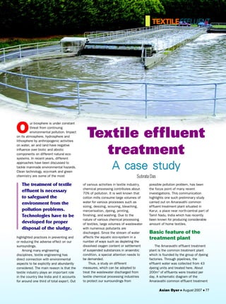
The treatment of textile
effluent is necessary
to safeguard the
environment from the
pollution problems.
Technologies have to be
developed for proper
disposal of the sludge.
Textile effluent
treatment
A case study
Subrata Das
Asian Dyer August 2007 77
2. Asian Dyer August 2007 78
TEXTILEEFFLUENT
plant is indicated in Fig 1. Dimensions
of different plant components are
detailed in Table 1.
Treatment of textile
effluents
Composition of the
feed to the plant
The feed consists of the different
kind of solid and liquid wastes from
different textile processing plants. Wet
processing of textiles involves unit
operations such as desizing, scouring,
bleaching, dyeing and finishing. Different
auxiliaries are used either in solid or in
liquid form to the textile product to obtain
the desired effect. Cotton textiles cannot
be dyed evenly without removing its natural
and added impurities, which inhibit the
proper penetration of dyes and chemicals.
Thus, treatment with various chemical
agents such as enzyme, alkalis, acids,
salts, surfactants, solvents, oxidising
and reducing bleaching agents etc are
necessary prior to dyeing. In the process
above ingredients which are used in the
preparatory processes and in actual
dyeing process (Table 2).
The effluent treatment method is
broadly classified into three main
categories: physical, chemical, and
biological treatments. There are four
stages : preliminary, primary, secondary,
and tertiary treatments to treat the
effluents. The preliminary treatment
processes are equalisation and
neutralisation. The primary stages involve
screening, sedimentation, floatation, and
flocculation. Secondary stages are used to
reduce the organic load, facilitate physical
/ chemical separation and biological
oxidation. Tertiary stages are important
because they serve as polishing of
effluent treatment.
Plant operation
The effluent water was collected
from 43 processing units and treated by
the following stages.
Screen chamber
Objective screens are provided to
remove relatively large solids to avoid
Fig 1 : Schematic diagram of Amaravathi
Common Effluent Treatment Plant
of dyeing, auxiliary
chemicals viz
Glauber’s salt,
sodium chloride and
other bio-salts are
added to exhaust the
dye from the liquor to
the substrate at
appropriate
temperature and pH.
Even after dyeing,
unfixed dyestuffs and
complex organic
products arising out
of the reaction with
textile substrate and
dyes are to be ade-
quately removed from
the surface of the
yarns/ fabrics to
achieve the proper
fastness require-
ments. So, waste
stream from the
dyeing industry which
is to be fed into the
effluent treatment
plant essentially
comprised of the
Table 1 : Plant components and dimensions
Components Numbers Dimensions (metre)
Screen chamber 1 4 x 1 x 3.5
Receiving sump 1 8 x 5.25
Equalisation tank 1 31 x 20 x 3
Flash mixer 1 1.7 x 1.7 x 1.7
Clarriflocculator 1 12 x 3.3
Aeration tank 2 23 x 16 x 3
2 22 x 16 x 3
Clarifier 2 13 x 4
Sludge well 1 6 x 3
Sludge thickener 1 7 x 3.3
Centrifuge 1 7 x 4
Generator room 1 7 x 3
Office/lab 1 12 x 6, 2 floors
Transformer yard 1 14 x 7.5
Sludge drying beds 12 4.9 x 4.9
Table 2 : Hazardous waste
Identity of Quantity State of Type of Mode of storage
hazardous generated of waste hazard and Disposal
waste stream
Sludge 2.5 mT Solid Chemical Packed in polyethylene
sludge bags and covered with
rain proof sheets
3. Asian Dyer August 2007 79
treated effluent and it was disposed out.
The outlet water quality is well within the
tolerance limit as delineated in the
norms of the Bureau of Indian Standards.
Through pipelines, the treated water was
disposed into the river water.
Sludge thickener
The inlet water consists of 60% water
and 40% solids. The effluents were passed
through the centrifuge. Due to centrifugal
action, the solids and liquids were been
separated. The sludge thickener reduces
the water content in the effluent to 40%
water and 60% solids. The effluent was
then reprocessed and the sludge was
collected at the bottom.
Drying beds
Primary and secondary sludge was
dried on the drying beds. Here the
sludge was subjected to solar
evaporation.
Difficulties in
operation
Each type of waste/waste stream
represents an individual problem which
can be solved only by taking into
consideration the following factors :
Local conditions
Dyestuff and chemical used
Amount and composition of the
waste water
Local drainage conditions
Region
Main sewage channel
Sewage characteristics etc.
Our aim is to adopt technologies
giving minimum or zero environmental
pollution. Effluents treatment plants are
the most widely accepted approaches
towards achieving environmental safety.
But, unfortunately, no single treatment
methodology is suitable or universally
adoptable for any kind of effluent
treatment. For instance, in the past,
biological treatment systems had been
used extensively but they are not
efficient for the colour removal of the
more resistant dyes. Therefore, the
treatment of waste stream needs to be
done by various methods, which include
physical, chemical and biological
treatment depending on pollution load
(Tables 3 and 4).
abrasion of mechanical equipments and
clogging of hydraulic system.
Collection tank
The collection tank collected the
effluent water from the screening
chamber and stored it, and then
pumped it to the equalisation tank.
Equalisation tank
The effluents do not have similar
concentrations at all the times; the pH
will vary time to time. The effluents
were stored from 8 to 12 hours in the
equalisation tank. This results in a
homogenous mixing of effluents and
helps in neutralisation. In addition, it
eliminates shock loading on the
subsequent treatment system.
Continuous mixing also eliminates
settling of solids within the equalisation
tank.
Flash mixer
Coagulants were added to the
effluents. They are :
Lime - (800-1000 ppm) - To raise the
pH 8-9
Ferrous sulphate - (200-300 ppm) -
To remove colour
Poly electrolyte - (0.2 ppm) - To
settle the suspended matters.
According to the above proportions,
the chemicals were added and mixed
with the effluents. The addition of the
above chemicals by efficient rapid
mixing facilitates homogeneous
combination of flocculates to produce
microflocs.
Clarriflocculator
In the clarriflocculator, the water
was circulated continuously by the
stirrer. Overflowed water was taken out
to the aeration tank. The solid particles
were settled down, and collected
separately and dried. Flocculation
provides slow mixing that leads to the
formation of macroflocs, which then
settle out in the clarifier zone. The
settled solids i.e. primary sludge was
pumped into sludge drying beds.
Aeration tank
The water was passed like a thin
film over the staircase arrangement.
Here the water got in direct contact
with the air to dissolve the oxygen into
water. BOD value of water was reduced
up to 90%.
Clarifier
The clarifier collects the biological
sludge. The overflowed water is called as
TEXTILEEFFLUENT
Table 3 : Effluent quality management (averaged for a month)
Quality parameters Inlet water Outlet water
pH 6 - 10 6.5 - 8.5
Biological oxygen demand 100 - 150 mg/l 20-30 mg/l
Chemical oxygen demand 300 - 400 mg/l 140 -250 mg/l
Total dissolved solids 2500 - 3000 mg/l 1800 - 2100 mg/l
Suspended solids 70 - 200 mg/l 50 - 90 mg/l
Chlorides 1000 - 1500 mg/l 700 - 1000 mg/l
Sulphides 1-2 mg/l Nil
Table 4 : Regulatory standards to which effluent needs to be treated
Quality parameters Tolerance limits
pH 5.5 - 9
Biological oxygen demand 30 mg/l
Chemical oxygen demand 250 mg/l
Total dissolved solids 2100 mg/l
Suspended solids 100 mg/l
Chlorides 1000 mg/l
Sulphides Nil
4. Asian Dyer August 2007 80
Solid waste disposal
Sludge management is the final stage
in textile effluent treatment process. Huge
amount of sludge was generated after
textile effluent treatment. The sludge was
collected and packed in polyethylene bags
and finally covered in the water proof
sheets. Sludge should be disposed off in
an offsite designated landfill area
recognised by the State Pollution Control
Board of Tamil Nadu, India.
Treated water disposal
The treatment plant disposed off the
treated effluent into the river water. In
Karur, availability of soft water is more.
So the treated effluents are not reused.
This treated water is in compliance with
the standards of agricultural usage. The
treatment plant strictly follows the rules
and regulation of the Bureau of Indian
Standards.
Conclusion
The treatment of textile effluent is the
necessary one to safeguard the
environment from the pollution problems.
Physical, chemical and biological
treatments were given to the effluents. The
sludge remained as solid mass; there is no
solution for sludge disposal. Technologies
have to be developed for proper disposal
of the sludge.
Dr Subrata Das obtained his PhD in
Textile Technology from IIT, Delhi. He
has around two decades of working
experience in R&D,
quality assurance
and teaching.
Dr Das is pre-
sently heading the
Consumer Testing
Services Labora-
tory of SGS India
Private Limited,
Bangalore. He has published technical
papers in reputed national/international
journals and made presentation at
various conferences.
TEXTILEEFFLUENT
VagotexWindtex is an Italian company whose
production and technology are exclusively made in Italy.
Windtex is a light stretch heat regulating membrane which
repels wind and water and maintains the microclimate
between the skin and the fabric.The manufacturers are
very proud of its light weight and in particular of its
elasticity. In fact other membranes which may otherwise be
similar toWindtex are heavier and do not have anything
like the same elasticity.
For this reason Windtex is the right choice for all
types of sports clothing. The advantages which derived
from this are innumerable, mainly because it is thermal
and breathable. The heat produced by a human being
varies from about 100 W when resting to over 1000 W
during physical effort. During winter sports, despite the
surrounding low temperatures, the body temperature
and as a result the production of heat increases. In
order to keep body temperature within certain limits,
heat is lost through perspiration. At this point, clothing
plays an important role : heat retention compromises
physical activity if the fabric does not breathe. Windtex's
excellent breathing capacity as well as its heat retention
Regulating membrane
protect the body's microclimate. Further characteristics
are : minimum bulk, freedom of movement, longer life,
full waterproof.
BesidesWindtex membrane, it is important to
underline thatVagotex has 20 years' experience in the field
of lamination and is able to offer a particularly wide range
of products in this field.Vagotex is a manufacturer, so the
whole manufacturing process is under their direct control.
They have a high level of experience based on years of
research and development, the continuous improvement
of products and techniques of production.They are thus
able to offer products which are differentiated according to
the clients' requirements and the different uses to which
they will be put.
The company's products are made to measure on the
bases of the clients' requests and are to be found in many
different sectors (clothing and footwear for sports, casual
clothing and footwear, gloves, accessories, underwear,
furnishings, tents and sleeping bags, the automotive sector,
orthopaedics, etc).Vagotex's techniques are exceptional in
that they are the result of the most modern lamination
systems and of the know how of their qualified staff.