
Recommended
More Related Content
What's hot
What's hot (20)
Similar to Industrial waste water purification procedure
Similar to Industrial waste water purification procedure (20)
Recently uploaded
Recently uploaded (20)
Industrial waste water purification procedure
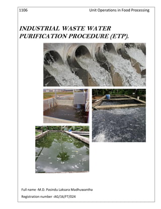
- 1. 1106 Unit Operations in Food Processing INDUSTRIAL WASTE WATER PURIFICATION PROCEDURE (ETP). . Full name -M.D. Pasindu Laksara Madhuwantha Registration number -AG/16/FT/024
- 2. Date-2018.07.22 Assignment number-01 Assignment name- Industrial Water Purification Procedure Objectives- To identify major parts in the Effluent Treatment Plant (ETP). To gain knowledge about the procedure of Effluent Treatment Plant (ETP). To learn unit operations used in the ETP. Introduction The effluent Treatment Plant (ETP) is a method that is used to treat the emanation coming out from many areas of the plant. It includes biological, physical, and chemical processes. It aims to releasing safe water into the environment to prevent it from getting cop0ntaminated. These plants are have been very useful in the process of providing clean water to the environment and have conserved water in a number of ways. Waste water treatment consists of applying known technology to improve or upgrade the quality of waste water. Waste water treatment involves collecti9ng the wastewater in a central, segregated location(The waste water treatment plant) and subjecting the waste water to various treatment process The principal objective of wastewater treatment is generally to allow human and industrial effluents to be disposed off without danger to human health or unacceptable damage to the natural environment. With the current emphasis on environment health and water pollution issues, there is an increasing awareness of the need to dispose of these wastewaters safety and beneficially.
- 3. ETP (Effluent Treatment Plant) is a process design for treating the industrial waste water for its reuse or safe disposal to the environment. •Influent: Untreated industrial waste water. •Effluent: Treated industrial waste water. •Sludge: Solid part separated from waste water by ETP. Need of ETP To clean industry effluent and recycle it for further use. To reduce the usage of fresh/potable water in Industries. To cut expenditure on water procurement. To meet the Standards for emission or discharge of environmental pollutants from various Industries set by the Government and avoid hefty penalties. To safeguard environment against pollution and contribute in sustainable development. Treatment Levels & Mechanisms of ETP Treatment levels: Preliminary Primary Secondary Tertiary (or advanced) Treatment mechanisms: Physical Chemical Biological Preliminary Treatment level Purpose: Physical separation of big sized impurities like cloth, plastics, wood logs, paper, etc. Common physical unit operations at Preliminary level are: Screening: A screen with openings of uniform size is used to remove large solids such as plastics, cloth etc. Generally maximum 10mm is used. Sedimentation: Physical water treatment process using gravity to remove suspended solids from water. Clarification: Used for separation of solids from fluids Primary Treatment Level Purpose: Removal of floating and settleable materials such as suspended solids and organic matter. Methods: Both physical and chemical methods are used in this treatment level. Chemical unit processes: Chemical unit processes are always used with physical operations and may also be used with biological treatment processes. Chemical processes use the addition of chemicals to the wastewater to bring about changes in its quality. Example: pH control, coagulation, chemical precipitation and oxidation. pH Control: To adjust the pH in the treatment process to make wastewater pH neutral. For acidic wastes (low pH): NaOH, Na2CO3, CaCO3or Ca(OH)2. For alkali wastes (high pH): H2SO4, HCl.
- 4. Chemical coagulation and Flocculation: Coagulation refers to collecting the minute solid particles dispersed in a liquid into a larger mass. Chemical coagulants like Al2(SO4)3{also called alum} or Fe2(SO4)3are added to wastewater to improve the attraction among fine particles so that they come together and form larger particles called flocs. A chemical flocculent (usually a polyelectrolyte) enhances the flocculation process by bringing together particles to form larger flocs , which settle out more quickly. Flocculation is aided by gentle mixing which causes the particles to collide. Secondary Treatment Level Methods: Biological and chemical processes are involved this level. Biological unit process To remove, or reduce concentration of organic and inorganic compounds. Biological treatment process can take many forms but all are based around microorganisms, mainly bacteria. Aerobic Processes Aerobic treatment processes take place in the presence of air (oxygen). Utilizes those microorganisms (aerobes), which use molecular/free oxygen to assimilate organic Impurities I.e. convert them in to carbon dioxide, water and biomass. Anaerobic Processes The anaerobic treatment processes take place in the absence of air (oxygen). Utilizes microorganisms (anaerobes) which do not require air (molecular/free oxygen) to assimilate Impurities. The final products are methane and biomass. Tertiary / Advanced treatment Purpose: Final cleaning process that improves wastewater quality before it is reused, recycled or discharged to the environment. Mechanism: Removes remaining inorganic compounds, and substances, such as the nitrogen and phosphorus. Bacteria, viruses and parasites, which are harmful to public health, are also removed at this stage. Methods: Alum: Used to help remove additional phosphorus particles and group the remaining solids together for Removal in the filters. Chlorine contact tank disinfects the tertiary treated wastewater by removing microorganisms in treated Wastewater including bacteria, viruses and parasites. Remaining chlorine is removed by adding sodium bisulphate just before it's discharged. ETP Plant Operation 1. Screen chamber: Remove relatively large solids to avoid abrasion of mechanical equipment and clogging of hydraulic system. 2. Collection tank: The collection tank collects the effluent water from the screening chamber, stores and then pumps it to the equalization tank. 3. Equalization tank: The effluents do not have similar concentrations at all the time; the pH will vary time to time. Effluents are stored from 8 to 12 hours in the equalization tank resulting in a homogenous mixing of effluents and helping in neutralization. It eliminates shock loading on the subsequent treatment system.
- 5. Continuous mixing also eliminates settling of solids within the equalization tank. Reduces SS, TSS. 4. Flash mixer: Coagulants were added to the effluents: 1. Lime :( 800-1000 ppm) To correct the pH upto8-9 2. Alum: (200-300 ppm) to remove colour 3. Poly electrolyte :( 0.2 ppm) to settle the suspended matters & reduce SS, TSS. The addition of the above chemicals by efficient rapid mixing facilitates homogeneous combination of flocculates to produce microflocs. 5. Clarriflocculator: In the clarriflocculator the water is circulated continuously by the stirrer. Overflowed water is taken out to the aeration tank. The solid particles are settled down, and collected separately and dried; this reduces SS, TSS. Flocculation provides slow mixing that leads to the formation of macro flocs, which then settles out in the clarifier zone. The settled solids i.e. primary sludge are pumped into sludge drying beds. 6. Aeration tank: The water is passed like a thin film over the different arrangements like staircase shape. Dosing of Urea and DAP is done. Water gets direct contact with the air to dissolve the oxygen into water. BOD & COD values of water is reduced up to 90%. 7. Clarifier: The clarifier collects the biological sludge. The overflowed water is called as treated effluent and disposed out. The outlet water quality is checked to be within the accepted limit as delineated in the norms of the Central Environment Authority. Through pipelines, the treated water is disposed into the environment river water, barren land, etc. 8. Sludge thickener: The inlet water consists of 60% water + 40% solids. The effluent is passed through the centrifuge. Due to centrifugal action, the solids and liquids are separated. The sludge thickener reduces the water content in the effluent to 40% water + 60% solids. The effluent is then reprocessed and the sludge collected at the bottom. 9. Drying beds: Primary and secondary sludge is dried on the drying beds. Composition of waste water with quantity Parameter Amount pH 4.0-5.0 BOD(Biological Oxygen Demand) 8000-15000mgO2/l COD (Chemical Oxygen Demand 15000-25000mgO2/l TSS(Total Suspended Solid) 1000-2500mg/l Oil and Grease 400-1500mg/l
- 6. Influent Effluent Sludge Effluent discharge Sludge discharge Flow chart of ETP Recycle tank Biological Treatment & Aeration {Dosing = (Urea + DAP) for O2} BOD removal ~ 90% COD removal ~ 90% Sedimentation tank {pH = 7.5} Sludge thickening unit Equalization (Lime + Alum) pH = 8.5 SS, TSS removal Disperse unit Screening Fish pond
- 7. Screening Screening is the filtration process for the separation of coarse particles from influent. Stainless steel net with varying pore size can be utilized. Screens are cleaned regularly to avoid clogging. Equalization tank Equalization makes the waste water homogenous. Retention time depends upon the capacity of treatment plant. (Generally 8-16 hours) Spray of water coming from dyeing unit Influent from Cool & Homogenous Screening influent to pH Correction Tank Air for diffusion pH correction In this tank pH of the influent is corrected to meet the standard. Acid or alkali is added to the effluent to increase or decrease the pH. Acid or alkali Influent from Influent of desired Equalization tank to pH disperse unit Disperse unit Disperse tank mixes the sludge coming from recycle tank with waste water for to proper aeration. Sludge from recycle tank Influent from pH Mixed influent & Correction tank sludge to aeration Equalization tank pH correction Disperse unit (Mixing of sludge & waste)
- 8. Aeration Function of aeration is oxidation by blowing air. Aerobic bacteria is used to stabilize and remove organic material presents in waste. Schematic diagram of aeration Aerobic bacteria Discharge to Mixture of waste sedimentation tank Water & sludge Air (Oxygen) Reaction in aeration tank: Organic matter + Oxygen Carbon dioxide + Water + Heat Bacteria nutrient Sedimentation tank In this tank sludge is settled down. Effluent is discharged from plant through a fish pond. Sludge is passed to the sludge thickening unit. Schematic diagram of sedimentation tank Waste water from Sludge to Sedimentation pack thickening unit Effluent Effluent Discharge Fish pond Fish Pond is used to see survival of fishes to ascertain fitness of water for disposal Aeration tank Aeration tank
- 9. Sludge thickening unit Partial amount of sludge is returned back to the aeration tank from thickening unit through recycle tank called return sludge tank and disperse tank. Schematic diagram of sludge thickening unit Sludge from Sludge discharge Sedimentation unit Sludge to recycle tank Return sludge tank Function of return tank or recycle tank is to mix water with sludge This mixture is then passed to aeration tank through disperse tank. Advantage of recycle sludge to aeration tank Sludge again oxidized to minimize the pollution from sludge. Alive bacteria of sludge is again used in aeration to utilize this bacteria. Sludge from Sludge to aeration tank Thickening unit through disperse unit Mixing of sludge & water Composition of discharge water with amounts Parameter Amount pH 5.5.-9.0 BOD(Biological Oxygen Demand) 250mgO2/l COD (Chemical Oxygen Demand) 400mgO2/l TSS(Total Suspended Solid) 2100mg/l Oil and Grease 10mg/l Sludge thickening unit Sludge recycle tank