SlideShare a Scribd company logo
1 of 6
Part –A Questions
UNIT -1
1. Define propagation constant.
2. A transmission line has ZO =74∟-12º Ω and is terminated with ZR=100 Ω.
Calculate the reflection loss
3. Find the attenuation and phase shift constant of a wave propagating along the line
whose propagation constant is (1.048× 10⁻⁴)∟88.8° .
4. Draw the equivalent circuit of a transmission line.
5. What are the transmission line parameters?
6. Write the value of reflection coefficient of the following loads. a)open circuit
b)short circuit
7. What is a distortion less line? What is the condition for a distortion less line?
8. What is an infinite line?
9. If a line is to have neither frequency nor phase distortion, how do you relate
attenuation constant and velocity of propagation to frequency?
10. Define Delay distortion and frequency Distortion.
UNIT -2
1. State the assumptions made for the analysis of the performance of the line at high
frequencies.
2. Give the minimum and maximum value of SWR and reflection coefficient
3. Define standing waves
4. A lossless line has a characteristic impedance of (20-45j)Ω .Determine the standing
wave ratio if the receiving end impedance is (10+5j) Ω
5. Give the relationship between standing wave ratio S and reflection coefficient K.
6. Find the maximum and minimum input impedances of a line with characteristic
impedance of 100 ohms and Standing wave ratio S is 3.
7. A lossless line has a standing wave ratio of 3.The R0 is 100 ohms and the minimum
voltage measured on the line is 125V.Find the power being delivered to the load.
8. How will you make standing wave measurements on a Coaxial line?
9. For the line of zero dissipation, what will be the values of attenuation constant and
characteristic impedance
10. Dissipation less transmission line has a shunt capacitance of 100pF/m and a series
inductance of 4µH/m. Determine the characteristic impedance.
UNIT -3
1. What is Smith Chart? State its applications.
2. Mention the applications of a quarter wave line.
3. Why a quarter wave line is considered as impedance inverter? Justify.
4. What are the applications of smith chart?
5. A 90 Ω lossless transmission line is to be matched to a load resistance of ZL=500Ω
via quarter wave section. Find the characteristic impedance for the quarter wave
transformer
6. List the procedural steps to find the admittance from the given impedance using
smith chart.
7. A transmission line has the reflection coefficient of 0.18∟400 and wavelength of
0.375m. Find the length of Short Circuited Stub.
8. Why short circuited stub is preferred to open circuited stub?
9. What are the disadvantages of single stub matching?
10. Distinguish between single stub matching and double stub matching.
UNIT -4
1. A pair of perfectly conducting plates is separated by 10cm in air and carries a
signal frequency of 6GHz in TE1 mode. Find Cut-off frequency and cutoff
wavelength.
2. A TEM wave at 2 MHz propagates in the region between conducting planes which
is filled with a dielectric material of εr = 2 and μr = 2 . Find the phase constant
3. A wave guide can be called as high pass filter. Why?
4. List the characteristics of TEM waves.
5. Define the terms phase velocity and group velocity.
6. A rectangular waveguide of cross section 5 cm x 2 cm is used to propagate TE11
mode at 10 GHz. Determine the cut-off wave length.
7. Why TEM wave is not possible in hollow wave guides?
8. What is the dominant mode of a rectangular waveguide? Why?
9. A rectangular air filled copper waveguide with dimension of a=3.4cm and b=1.2cm
has a 9.2 GHz signal propagated in it. Determine the guide wavelength for TE10
mode.
10. Justify, why TM01 and TM10 modes in a rectangular waveguide do not exists.
11. What are Cavity Resonators? Mention its applications.
UNIT -5
1. Define Transducer Power gain.
2. List the applications of RF/microwave signals
3. Draw the cross section of multifinger Bipolar Junction Transistor
4. List some of the active RF components.
5. Draw the Structure of HEMT.
6. Define Stability.
7. Write the Condition for unconditional Stability.
8. List the parameters of RF amplifier.
9. Draw the Structure of RF mixer.
10. Write the Condition for conditional Stability.
11. What are S parameters? Why is s-matrix used in RF/Microwave analysis?
PART-B and PART -C Questions
UNIT -1
1. Derive the expression for voltage and current at any point on a transmission line.
(13)
2. A generator of 1 volt, 1KHz, supplies power to a 100 km open wire line terminated
in Zo. The line parameters are R=10.4 ohms/ km, L=0.00367henry/ km,
G=0.8×10⁻⁶mho/ km, C=0.00835 uf/ km. Calculate Characteristic Impedance,
Propagation constant, attenuation constant, Phase constant, wavelength, velocity of
propagation, sending current, Receiving current, received voltage and received
power. (15)
3. (i) Derive the expression for the input impedance of a transmission line. (8)
(ii)A transmission line has the following per unit length parameters L=0.1µH,R=5
Ω, -C=300pF and G=0.01Ʊ. Calculate propagation constant and characteristic
impedance at 500MHz. (5)
4. i) Explain about an infinite line (5)
(ii) A 2 meter long transmission line with Characteristic impedance of 60+j40
ohms operating at ω=106 radians / sec has attenuation constant of 0.921
nepers/m and phase shift constant of 0 rad/m.If the line is terminated in a load
of 20 +j50 ohms, determine the input impedance of a line. (8)
5. (i) Explain reflection on a line not terminated in characteristic impedance. What are
the disadvantages of reflection? (7)
(ii) Derive the input impedance of a open and short circuited line. (6)
6. (i) Explain in detail about waveform distortion and also derive the condition for
distortion less transmission line. (8)
(ii) Derive the expression for transfer impedance of a Transmission Line. (5)
7. What is the need for loading? Derive the propagation constant of a continuously
loaded line and also derive Campbell’s equation. (13)
UNIT -2
1. (i)Derive the line constants of Zero dissipationless line (7)
(ii)A radio frequency line with Z0=70 ohms is terminated by ZL=115-j80Ω at λ=2.5
m. Find the VSWR and the maximum and minimum line impedances. (6)
2. Derive the expressions for voltage and current at any point on the dissipationless
line terminated in terminating impedance. Obtain the same for different receiving
end conditions. (13)
3. Discuss the various parameters of open wire line and coaxial cable at radio
frequency (13)
4. (i)A line with zero dissipation has R=0.006ohms/m, L=2.5 μH/m, C=4.45pF/m. If
the line is operated at 10 MHz find (i)Ro (ii)attenuation constant (iii)phase
Constant (iv) Velocity of propagation and (v) wavelength. (7)
(ii)An open wire line consists of two copper conductors each of radius 2mm and is
separated by a distance of 250mm in air. If the frequency of the signal is 40
KHz, Calculate the following per unit length of the line Inductance, Capacitance,
DC resistance given that conductivity of copper is 5.75×10⁷mho/m and ac
resistance. (6)
5. (i)Derive an expression for the input impedance of the dissipationless line. Deduce
the input impedance of open and short circuited dissipationless lines.
(ii) Derive the relationship between SWR and Reflection coefficient .
6. (i)Explain the different methods of measuring the VSWR on transmission lines.
(6)
(ii) Explain the method of power and impedance measurement on the
dissipationless line. (7)
UNIT -3
1. Prove that the input impedance of the quarter wave line is Zin = R0
2/ZR. (6)
Design a quarter wave transformer to match a load of 200 Ω to a source resistance
of 500 Ω. Operating frequency is 200 MHz. (7)
2. Derive analytically the location and length of single stub for impedance matching.
(13)
3. (i) Explain the principle of Single stub matching.(7)
(ii) Design a single stub matching system to match a load of1 50+j225 ohms for a
75 ohms line operating at 500 MHz using relevant formula. (6)
4. Draw and explain the principle of double stub matching with neat diagram and
expressions.(13)
5. A 50 Ω lossless transmission line is terminated in a load impedance of ZL=
(25+j50) Ω. Use the smith chart top find voltage reflection coefficient, VSWR,
input impedance of the line, given that the line is 3.3 λ long and input admittance of
the line. (13)
6. A transmission line 100m long is terminated in a load of 100-j200 Ω. Determine
the line impedance at 25m from the load end at a frequency of 10MHz. Assume
line impedance of 100Ω. Determine the input impedance and Admittance using
Smith chart. Also find SWR ,Reflection coefficient(13)
7. A load (50-j100) Ω is connected across a 75 Ω line. Design a short circuited stub to
provide impedance matching at 50 MHz using SMITH chart. (13)
8. Determine length and location of short circuited stub to produce an impedance
match on a transmission line with characteristic impedance of 600 ohm and
teminated in 1800 ohm at 50 MHz using Smith chart. (13)
9. For a transmission line with a characteristic impedance of 100 Ω and a load with a
complex impedance ZL= (300+j250)Ω functioning at 500MHz,Calculate the stub
length and the distance of the stub from load using SMITH chart (15)
10. Determine the following (a) Standing Wave Ratio (b) Load Admittance (c)
Impedance of the transmission line at the maximum and minimum standing waves
on the line (d) distance between the load from first voltage maximum for a
transmission line of Z0 =50 ohms with a receiving end impedance of 100+j121
ohms. The wave length of the electrical signal along the line is 2m. (15)
UNIT -4
1. (i)Explain the transmission of Transverse Electric waves between parallel
perfectly conducting planes with necessary expressions and diagrams for field
components. (10)
(ii) If the plate separation is 7 cm in air, find the cutoff frequency and cutoff
wavelength for a signal propagating at 12 GHz for TE10 mode. (3)
2. (i) Explain the transmission of Transverse Magnetic waves between parallel
perfectly conducting planes with necessary expressions and diagrams for field
components. (10)
(ii)A TEM at 1MHz propagates in the region between the conducting planes
which is filled with a dielectric material of µr =1 and εr =2.Find the phase
constant and characteristic wave impedance. (3)
3. (i)Deduce the expressions for the field components of TE waves guided along a
rectangular wave guide.(10)
(ii) An air filled rectangular copper wave guide with a=2.28 cm and b=1.01 cm is
operated at 9.2 GHz in dominant mode. Determine the cutoff frequency and the
cutoff wave length. (3)
4. Explain the transmission of Transverse Electric waves in circular wave guide with
necessary expressions for field components.(13)
5. Using Bessel differential equation, Obtain the TM field components in circular
waveguides. (13)
6. (i) Derive the expressions for TM wave components rectangular wave guide using
Maxwell’s equations. (10)
(ii) An air filled rectangular copper wave guide with a=3 cm and b=1 cm is
operated at 10.5 GHz in dominant mode. Determine the guide wave length. (3)
7. A pair of perfectly conducting planes is separated by 7 cm in air and carries a
signal with a frequency of 6 GHz in TE1 mode. Find i) Cutoff frequency, ii) Phase
constant,iii) Attenuation constant and phase constant for 0.8 fc, iv) Cutoff
wavelength, v) Phase velocity, vi) Group velocity, vii) Wavelength measured along
the guiding walls, viii) Is it possible to propagate TE3 mode.
8. A TE10 wave at 10 GHz propagates in a X-band copper rectangular waveguide with
inner dimensions a = 2.3 cm and b = 1 cm which is filled with Teflon (εr = 2.1,
μ r = 1). Calculate cutoff frequency, velocity of propagation, phase velocity, phase
constant, guide wavelength, phase velocity and wave impedance.
UNIT -5
1. Explain the Bipolar Junction Transistor at Radio Frequency. (13)
2. Explain in detail about the construction and functionality of High Electron Mobility
Transistors. (13)
3. Explain the Field Effect Transistor at Radio Frequency. (13)
4. Derive the various power gains for a two port RF network considering the stability
of the amplifier involved. (13)
5. Discuss about input and output stability circles in the complex ГL and ГS planes.
(13)
6. An RF amplifier has the following S parameters: S11=0.3∟-70°, S21=3.5∟85°,
S12=0.2∟-10°, S22=0.4∟-45°. Further Vs=5V∟0°, Zs=40Ω and ZL=73Ω.
Assuming Z0=50Ω. Find GT, GTU, GA and G. Also find Power delivered to the load
LP , available power from source AP and incident power to amplifier incP
7. Explain the following
a. Voltage controlled Oscillator
b. Mixers

More Related Content

What's hot

What's hot (20)

219272664 s-parameters
219272664 s-parameters219272664 s-parameters
219272664 s-parameters
 
Antenna
AntennaAntenna
Antenna
 
Smart Antenna
Smart AntennaSmart Antenna
Smart Antenna
 
Antenna design
Antenna designAntenna design
Antenna design
 
Log periodic antenna
Log periodic antennaLog periodic antenna
Log periodic antenna
 
FUNDAMENTAL PARAMETERS OF ANTENNA
FUNDAMENTAL PARAMETERS OF ANTENNAFUNDAMENTAL PARAMETERS OF ANTENNA
FUNDAMENTAL PARAMETERS OF ANTENNA
 
Ph.D Research proposal
Ph.D Research proposalPh.D Research proposal
Ph.D Research proposal
 
Basics of microstrip slot line
Basics of microstrip slot lineBasics of microstrip slot line
Basics of microstrip slot line
 
Fractal antenna by Nisheeth Paliwal
Fractal antenna by Nisheeth PaliwalFractal antenna by Nisheeth Paliwal
Fractal antenna by Nisheeth Paliwal
 
Microstrip TL 1st 3
Microstrip TL 1st 3Microstrip TL 1st 3
Microstrip TL 1st 3
 
Design of band notched antenna for ultra wide band applications
Design of band notched antenna for ultra wide band applicationsDesign of band notched antenna for ultra wide band applications
Design of band notched antenna for ultra wide band applications
 
Antenna (2)
Antenna (2)Antenna (2)
Antenna (2)
 
Diversity Techniques in Wireless Communication
Diversity Techniques in Wireless CommunicationDiversity Techniques in Wireless Communication
Diversity Techniques in Wireless Communication
 
Introduction to rf and microwave circuits
Introduction to rf and microwave circuitsIntroduction to rf and microwave circuits
Introduction to rf and microwave circuits
 
Measurements of Rediation Resistance in Antenna
Measurements of Rediation Resistance in AntennaMeasurements of Rediation Resistance in Antenna
Measurements of Rediation Resistance in Antenna
 
Mm wave
Mm waveMm wave
Mm wave
 
Antenna PARAMETERS
Antenna PARAMETERSAntenna PARAMETERS
Antenna PARAMETERS
 
Design and Implementation of Reconfigurable Antenna
Design and Implementation of Reconfigurable AntennaDesign and Implementation of Reconfigurable Antenna
Design and Implementation of Reconfigurable Antenna
 
Reflector antennas
Reflector antennasReflector antennas
Reflector antennas
 
A seminar presentation on "Design and Simulation of E and U shape Microstrip ...
A seminar presentation on "Design and Simulation of E and U shape Microstrip ...A seminar presentation on "Design and Simulation of E and U shape Microstrip ...
A seminar presentation on "Design and Simulation of E and U shape Microstrip ...
 

Similar to EC8651 Transmission lines and RF systems

Electronics assignments(Transistors,OPAMPS)
Electronics assignments(Transistors,OPAMPS)Electronics assignments(Transistors,OPAMPS)
Electronics assignments(Transistors,OPAMPS)
soumyaranjan panda
 

Similar to EC8651 Transmission lines and RF systems (20)

Tutorial no. 7
Tutorial no. 7Tutorial no. 7
Tutorial no. 7
 
Attena (1)
Attena (1)Attena (1)
Attena (1)
 
Cntl model paper
Cntl model paperCntl model paper
Cntl model paper
 
Ec 55 transmission lines and waveguides b
Ec 55 transmission lines and waveguides bEc 55 transmission lines and waveguides b
Ec 55 transmission lines and waveguides b
 
Transmission lines assignment 1(2019 2020)
Transmission lines assignment 1(2019 2020)Transmission lines assignment 1(2019 2020)
Transmission lines assignment 1(2019 2020)
 
EHVAC-question-bank-pdf.pdf
EHVAC-question-bank-pdf.pdfEHVAC-question-bank-pdf.pdf
EHVAC-question-bank-pdf.pdf
 
Ec8651 transmissions lines and rf systems
Ec8651  transmissions lines and rf systemsEc8651  transmissions lines and rf systems
Ec8651 transmissions lines and rf systems
 
transmission line theory prp
transmission line theory prptransmission line theory prp
transmission line theory prp
 
EC8651 Transmissions lines and RF systems-two marks
EC8651  Transmissions lines and RF systems-two marksEC8651  Transmissions lines and RF systems-two marks
EC8651 Transmissions lines and RF systems-two marks
 
Transmission lines and waveguides -Two marks
Transmission lines and waveguides -Two marksTransmission lines and waveguides -Two marks
Transmission lines and waveguides -Two marks
 
Electronics assignments
Electronics assignmentsElectronics assignments
Electronics assignments
 
Electronics assignments(Transistors,OPAMPS)
Electronics assignments(Transistors,OPAMPS)Electronics assignments(Transistors,OPAMPS)
Electronics assignments(Transistors,OPAMPS)
 
H010526975
H010526975H010526975
H010526975
 
17437 radio reception
17437 radio reception17437 radio reception
17437 radio reception
 
Short And Medium Lines
Short And Medium LinesShort And Medium Lines
Short And Medium Lines
 
TLW_Unit I material pdf.ppt
TLW_Unit I material pdf.pptTLW_Unit I material pdf.ppt
TLW_Unit I material pdf.ppt
 
Vlsi model question paper 1
Vlsi model question paper 1Vlsi model question paper 1
Vlsi model question paper 1
 
Design of a 600 mhz ddipole antenna
Design of a 600 mhz ddipole antennaDesign of a 600 mhz ddipole antenna
Design of a 600 mhz ddipole antenna
 
174072012 ee2404-lm
174072012 ee2404-lm174072012 ee2404-lm
174072012 ee2404-lm
 
199833536 ee2404-lab-manual
199833536 ee2404-lab-manual199833536 ee2404-lab-manual
199833536 ee2404-lab-manual
 

More from Dr.SHANTHI K.G

More from Dr.SHANTHI K.G (20)

unit4 DTFT .pptx
unit4 DTFT .pptxunit4 DTFT .pptx
unit4 DTFT .pptx
 
unit4 sampling.pptx
unit4 sampling.pptxunit4 sampling.pptx
unit4 sampling.pptx
 
Fourier and Laplace transforms in analysis of CT systems PDf.pdf
Fourier and Laplace transforms in analysis of CT systems PDf.pdfFourier and Laplace transforms in analysis of CT systems PDf.pdf
Fourier and Laplace transforms in analysis of CT systems PDf.pdf
 
Laplace Transform Problems
Laplace Transform ProblemsLaplace Transform Problems
Laplace Transform Problems
 
Orthogonal coordinate systems- Cartesian ,Cylindrical ,Spherical
Orthogonal coordinate systems- Cartesian ,Cylindrical ,SphericalOrthogonal coordinate systems- Cartesian ,Cylindrical ,Spherical
Orthogonal coordinate systems- Cartesian ,Cylindrical ,Spherical
 
Fourier Transform ,LAPLACE TRANSFORM,ROC and its Properties
Fourier Transform ,LAPLACE TRANSFORM,ROC and its Properties Fourier Transform ,LAPLACE TRANSFORM,ROC and its Properties
Fourier Transform ,LAPLACE TRANSFORM,ROC and its Properties
 
Unit-1 Classification of Signals
Unit-1 Classification of SignalsUnit-1 Classification of Signals
Unit-1 Classification of Signals
 
Unit 1 Operation on signals
Unit 1  Operation on signalsUnit 1  Operation on signals
Unit 1 Operation on signals
 
Scope of signals and systems
Scope of signals and systemsScope of signals and systems
Scope of signals and systems
 
Unit 1 -Introduction to signals and standard signals
Unit 1 -Introduction to signals  and standard signalsUnit 1 -Introduction to signals  and standard signals
Unit 1 -Introduction to signals and standard signals
 
Unit V-Electromagnetic Fields-Normal incidence at a plane dielectric boundary...
Unit V-Electromagnetic Fields-Normal incidence at a plane dielectric boundary...Unit V-Electromagnetic Fields-Normal incidence at a plane dielectric boundary...
Unit V-Electromagnetic Fields-Normal incidence at a plane dielectric boundary...
 
UNIT IV - WAVE EQUATIONS AND THEIR SOLUTION
UNIT IV - WAVE EQUATIONS AND THEIR SOLUTION UNIT IV - WAVE EQUATIONS AND THEIR SOLUTION
UNIT IV - WAVE EQUATIONS AND THEIR SOLUTION
 
TIME-VARYING FIELDS AND MAXWELL's EQUATIONS -Unit 4 -Notes
 TIME-VARYING FIELDS AND MAXWELL's EQUATIONS -Unit 4 -Notes TIME-VARYING FIELDS AND MAXWELL's EQUATIONS -Unit 4 -Notes
TIME-VARYING FIELDS AND MAXWELL's EQUATIONS -Unit 4 -Notes
 
TIME-VARYING FIELDS AND MAXWELL's EQUATIONS -Unit 4 - two marks
 TIME-VARYING FIELDS AND MAXWELL's EQUATIONS -Unit 4 - two marks TIME-VARYING FIELDS AND MAXWELL's EQUATIONS -Unit 4 - two marks
TIME-VARYING FIELDS AND MAXWELL's EQUATIONS -Unit 4 - two marks
 
TIME-VARYING FIELDS AND MAXWELL's EQUATIONS -Unit4- problems
 TIME-VARYING FIELDS AND MAXWELL's EQUATIONS -Unit4- problems TIME-VARYING FIELDS AND MAXWELL's EQUATIONS -Unit4- problems
TIME-VARYING FIELDS AND MAXWELL's EQUATIONS -Unit4- problems
 
Unit-3:Magnetostatics
Unit-3:MagnetostaticsUnit-3:Magnetostatics
Unit-3:Magnetostatics
 
Electric potential, Electric Field and Potential due to dipole
Electric potential, Electric Field and Potential due to dipoleElectric potential, Electric Field and Potential due to dipole
Electric potential, Electric Field and Potential due to dipole
 
Gauss law and its Applications
Gauss law and its ApplicationsGauss law and its Applications
Gauss law and its Applications
 
Electric field intensity due to a charged ring and Electric flux density
Electric field intensity due to a charged ring and Electric flux densityElectric field intensity due to a charged ring and Electric flux density
Electric field intensity due to a charged ring and Electric flux density
 
Electric field intensity due to infinite line charge and infinte sheet of charge
Electric field intensity due to infinite line charge and infinte sheet of chargeElectric field intensity due to infinite line charge and infinte sheet of charge
Electric field intensity due to infinite line charge and infinte sheet of charge
 

Recently uploaded

Call Girls In Bangalore ☎ 7737669865 🥵 Book Your One night Stand
Call Girls In Bangalore ☎ 7737669865 🥵 Book Your One night StandCall Girls In Bangalore ☎ 7737669865 🥵 Book Your One night Stand
Call Girls In Bangalore ☎ 7737669865 🥵 Book Your One night Stand
amitlee9823
 
Top Rated Call Girls In chittoor 📱 {7001035870} VIP Escorts chittoor
Top Rated Call Girls In chittoor 📱 {7001035870} VIP Escorts chittoorTop Rated Call Girls In chittoor 📱 {7001035870} VIP Escorts chittoor
Top Rated Call Girls In chittoor 📱 {7001035870} VIP Escorts chittoor
dharasingh5698
 
FULL ENJOY Call Girls In Mahipalpur Delhi Contact Us 8377877756
FULL ENJOY Call Girls In Mahipalpur Delhi Contact Us 8377877756FULL ENJOY Call Girls In Mahipalpur Delhi Contact Us 8377877756
FULL ENJOY Call Girls In Mahipalpur Delhi Contact Us 8377877756
dollysharma2066
 
VIP Call Girls Palanpur 7001035870 Whatsapp Number, 24/07 Booking
VIP Call Girls Palanpur 7001035870 Whatsapp Number, 24/07 BookingVIP Call Girls Palanpur 7001035870 Whatsapp Number, 24/07 Booking
VIP Call Girls Palanpur 7001035870 Whatsapp Number, 24/07 Booking
dharasingh5698
 

Recently uploaded (20)

Navigating Complexity: The Role of Trusted Partners and VIAS3D in Dassault Sy...
Navigating Complexity: The Role of Trusted Partners and VIAS3D in Dassault Sy...Navigating Complexity: The Role of Trusted Partners and VIAS3D in Dassault Sy...
Navigating Complexity: The Role of Trusted Partners and VIAS3D in Dassault Sy...
 
KubeKraft presentation @CloudNativeHooghly
KubeKraft presentation @CloudNativeHooghlyKubeKraft presentation @CloudNativeHooghly
KubeKraft presentation @CloudNativeHooghly
 
Thermal Engineering Unit - I & II . ppt
Thermal Engineering  Unit - I & II . pptThermal Engineering  Unit - I & II . ppt
Thermal Engineering Unit - I & II . ppt
 
Water Industry Process Automation & Control Monthly - April 2024
Water Industry Process Automation & Control Monthly - April 2024Water Industry Process Automation & Control Monthly - April 2024
Water Industry Process Automation & Control Monthly - April 2024
 
Double Revolving field theory-how the rotor develops torque
Double Revolving field theory-how the rotor develops torqueDouble Revolving field theory-how the rotor develops torque
Double Revolving field theory-how the rotor develops torque
 
Call Girls In Bangalore ☎ 7737669865 🥵 Book Your One night Stand
Call Girls In Bangalore ☎ 7737669865 🥵 Book Your One night StandCall Girls In Bangalore ☎ 7737669865 🥵 Book Your One night Stand
Call Girls In Bangalore ☎ 7737669865 🥵 Book Your One night Stand
 
Block diagram reduction techniques in control systems.ppt
Block diagram reduction techniques in control systems.pptBlock diagram reduction techniques in control systems.ppt
Block diagram reduction techniques in control systems.ppt
 
Top Rated Call Girls In chittoor 📱 {7001035870} VIP Escorts chittoor
Top Rated Call Girls In chittoor 📱 {7001035870} VIP Escorts chittoorTop Rated Call Girls In chittoor 📱 {7001035870} VIP Escorts chittoor
Top Rated Call Girls In chittoor 📱 {7001035870} VIP Escorts chittoor
 
Generative AI or GenAI technology based PPT
Generative AI or GenAI technology based PPTGenerative AI or GenAI technology based PPT
Generative AI or GenAI technology based PPT
 
chapter 5.pptx: drainage and irrigation engineering
chapter 5.pptx: drainage and irrigation engineeringchapter 5.pptx: drainage and irrigation engineering
chapter 5.pptx: drainage and irrigation engineering
 
Design For Accessibility: Getting it right from the start
Design For Accessibility: Getting it right from the startDesign For Accessibility: Getting it right from the start
Design For Accessibility: Getting it right from the start
 
FULL ENJOY Call Girls In Mahipalpur Delhi Contact Us 8377877756
FULL ENJOY Call Girls In Mahipalpur Delhi Contact Us 8377877756FULL ENJOY Call Girls In Mahipalpur Delhi Contact Us 8377877756
FULL ENJOY Call Girls In Mahipalpur Delhi Contact Us 8377877756
 
VIP Call Girls Palanpur 7001035870 Whatsapp Number, 24/07 Booking
VIP Call Girls Palanpur 7001035870 Whatsapp Number, 24/07 BookingVIP Call Girls Palanpur 7001035870 Whatsapp Number, 24/07 Booking
VIP Call Girls Palanpur 7001035870 Whatsapp Number, 24/07 Booking
 
CCS335 _ Neural Networks and Deep Learning Laboratory_Lab Complete Record
CCS335 _ Neural Networks and Deep Learning Laboratory_Lab Complete RecordCCS335 _ Neural Networks and Deep Learning Laboratory_Lab Complete Record
CCS335 _ Neural Networks and Deep Learning Laboratory_Lab Complete Record
 
ONLINE FOOD ORDER SYSTEM PROJECT REPORT.pdf
ONLINE FOOD ORDER SYSTEM PROJECT REPORT.pdfONLINE FOOD ORDER SYSTEM PROJECT REPORT.pdf
ONLINE FOOD ORDER SYSTEM PROJECT REPORT.pdf
 
Double rodded leveling 1 pdf activity 01
Double rodded leveling 1 pdf activity 01Double rodded leveling 1 pdf activity 01
Double rodded leveling 1 pdf activity 01
 
Booking open Available Pune Call Girls Koregaon Park 6297143586 Call Hot Ind...
Booking open Available Pune Call Girls Koregaon Park  6297143586 Call Hot Ind...Booking open Available Pune Call Girls Koregaon Park  6297143586 Call Hot Ind...
Booking open Available Pune Call Girls Koregaon Park 6297143586 Call Hot Ind...
 
Booking open Available Pune Call Girls Pargaon 6297143586 Call Hot Indian Gi...
Booking open Available Pune Call Girls Pargaon  6297143586 Call Hot Indian Gi...Booking open Available Pune Call Girls Pargaon  6297143586 Call Hot Indian Gi...
Booking open Available Pune Call Girls Pargaon 6297143586 Call Hot Indian Gi...
 
VIP Model Call Girls Kothrud ( Pune ) Call ON 8005736733 Starting From 5K to ...
VIP Model Call Girls Kothrud ( Pune ) Call ON 8005736733 Starting From 5K to ...VIP Model Call Girls Kothrud ( Pune ) Call ON 8005736733 Starting From 5K to ...
VIP Model Call Girls Kothrud ( Pune ) Call ON 8005736733 Starting From 5K to ...
 
data_management_and _data_science_cheat_sheet.pdf
data_management_and _data_science_cheat_sheet.pdfdata_management_and _data_science_cheat_sheet.pdf
data_management_and _data_science_cheat_sheet.pdf
 

EC8651 Transmission lines and RF systems

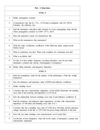
  • 1. Part –A Questions UNIT -1 1. Define propagation constant. 2. A transmission line has ZO =74∟-12º Ω and is terminated with ZR=100 Ω. Calculate the reflection loss 3. Find the attenuation and phase shift constant of a wave propagating along the line whose propagation constant is (1.048× 10⁻⁴)∟88.8° . 4. Draw the equivalent circuit of a transmission line. 5. What are the transmission line parameters? 6. Write the value of reflection coefficient of the following loads. a)open circuit b)short circuit 7. What is a distortion less line? What is the condition for a distortion less line? 8. What is an infinite line? 9. If a line is to have neither frequency nor phase distortion, how do you relate attenuation constant and velocity of propagation to frequency? 10. Define Delay distortion and frequency Distortion. UNIT -2 1. State the assumptions made for the analysis of the performance of the line at high frequencies. 2. Give the minimum and maximum value of SWR and reflection coefficient 3. Define standing waves 4. A lossless line has a characteristic impedance of (20-45j)Ω .Determine the standing wave ratio if the receiving end impedance is (10+5j) Ω 5. Give the relationship between standing wave ratio S and reflection coefficient K. 6. Find the maximum and minimum input impedances of a line with characteristic impedance of 100 ohms and Standing wave ratio S is 3. 7. A lossless line has a standing wave ratio of 3.The R0 is 100 ohms and the minimum voltage measured on the line is 125V.Find the power being delivered to the load. 8. How will you make standing wave measurements on a Coaxial line? 9. For the line of zero dissipation, what will be the values of attenuation constant and characteristic impedance
  • 2. 10. Dissipation less transmission line has a shunt capacitance of 100pF/m and a series inductance of 4µH/m. Determine the characteristic impedance. UNIT -3 1. What is Smith Chart? State its applications. 2. Mention the applications of a quarter wave line. 3. Why a quarter wave line is considered as impedance inverter? Justify. 4. What are the applications of smith chart? 5. A 90 Ω lossless transmission line is to be matched to a load resistance of ZL=500Ω via quarter wave section. Find the characteristic impedance for the quarter wave transformer 6. List the procedural steps to find the admittance from the given impedance using smith chart. 7. A transmission line has the reflection coefficient of 0.18∟400 and wavelength of 0.375m. Find the length of Short Circuited Stub. 8. Why short circuited stub is preferred to open circuited stub? 9. What are the disadvantages of single stub matching? 10. Distinguish between single stub matching and double stub matching. UNIT -4 1. A pair of perfectly conducting plates is separated by 10cm in air and carries a signal frequency of 6GHz in TE1 mode. Find Cut-off frequency and cutoff wavelength. 2. A TEM wave at 2 MHz propagates in the region between conducting planes which is filled with a dielectric material of εr = 2 and μr = 2 . Find the phase constant 3. A wave guide can be called as high pass filter. Why? 4. List the characteristics of TEM waves. 5. Define the terms phase velocity and group velocity. 6. A rectangular waveguide of cross section 5 cm x 2 cm is used to propagate TE11 mode at 10 GHz. Determine the cut-off wave length. 7. Why TEM wave is not possible in hollow wave guides? 8. What is the dominant mode of a rectangular waveguide? Why? 9. A rectangular air filled copper waveguide with dimension of a=3.4cm and b=1.2cm has a 9.2 GHz signal propagated in it. Determine the guide wavelength for TE10
  • 3. mode. 10. Justify, why TM01 and TM10 modes in a rectangular waveguide do not exists. 11. What are Cavity Resonators? Mention its applications. UNIT -5 1. Define Transducer Power gain. 2. List the applications of RF/microwave signals 3. Draw the cross section of multifinger Bipolar Junction Transistor 4. List some of the active RF components. 5. Draw the Structure of HEMT. 6. Define Stability. 7. Write the Condition for unconditional Stability. 8. List the parameters of RF amplifier. 9. Draw the Structure of RF mixer. 10. Write the Condition for conditional Stability. 11. What are S parameters? Why is s-matrix used in RF/Microwave analysis? PART-B and PART -C Questions UNIT -1 1. Derive the expression for voltage and current at any point on a transmission line. (13) 2. A generator of 1 volt, 1KHz, supplies power to a 100 km open wire line terminated in Zo. The line parameters are R=10.4 ohms/ km, L=0.00367henry/ km, G=0.8×10⁻⁶mho/ km, C=0.00835 uf/ km. Calculate Characteristic Impedance, Propagation constant, attenuation constant, Phase constant, wavelength, velocity of propagation, sending current, Receiving current, received voltage and received power. (15) 3. (i) Derive the expression for the input impedance of a transmission line. (8) (ii)A transmission line has the following per unit length parameters L=0.1µH,R=5 Ω, -C=300pF and G=0.01Ʊ. Calculate propagation constant and characteristic impedance at 500MHz. (5) 4. i) Explain about an infinite line (5) (ii) A 2 meter long transmission line with Characteristic impedance of 60+j40 ohms operating at ω=106 radians / sec has attenuation constant of 0.921
  • 4. nepers/m and phase shift constant of 0 rad/m.If the line is terminated in a load of 20 +j50 ohms, determine the input impedance of a line. (8) 5. (i) Explain reflection on a line not terminated in characteristic impedance. What are the disadvantages of reflection? (7) (ii) Derive the input impedance of a open and short circuited line. (6) 6. (i) Explain in detail about waveform distortion and also derive the condition for distortion less transmission line. (8) (ii) Derive the expression for transfer impedance of a Transmission Line. (5) 7. What is the need for loading? Derive the propagation constant of a continuously loaded line and also derive Campbell’s equation. (13) UNIT -2 1. (i)Derive the line constants of Zero dissipationless line (7) (ii)A radio frequency line with Z0=70 ohms is terminated by ZL=115-j80Ω at λ=2.5 m. Find the VSWR and the maximum and minimum line impedances. (6) 2. Derive the expressions for voltage and current at any point on the dissipationless line terminated in terminating impedance. Obtain the same for different receiving end conditions. (13) 3. Discuss the various parameters of open wire line and coaxial cable at radio frequency (13) 4. (i)A line with zero dissipation has R=0.006ohms/m, L=2.5 μH/m, C=4.45pF/m. If the line is operated at 10 MHz find (i)Ro (ii)attenuation constant (iii)phase Constant (iv) Velocity of propagation and (v) wavelength. (7) (ii)An open wire line consists of two copper conductors each of radius 2mm and is separated by a distance of 250mm in air. If the frequency of the signal is 40 KHz, Calculate the following per unit length of the line Inductance, Capacitance, DC resistance given that conductivity of copper is 5.75×10⁷mho/m and ac resistance. (6) 5. (i)Derive an expression for the input impedance of the dissipationless line. Deduce the input impedance of open and short circuited dissipationless lines. (ii) Derive the relationship between SWR and Reflection coefficient . 6. (i)Explain the different methods of measuring the VSWR on transmission lines. (6) (ii) Explain the method of power and impedance measurement on the dissipationless line. (7) UNIT -3 1. Prove that the input impedance of the quarter wave line is Zin = R0 2/ZR. (6) Design a quarter wave transformer to match a load of 200 Ω to a source resistance of 500 Ω. Operating frequency is 200 MHz. (7) 2. Derive analytically the location and length of single stub for impedance matching.
  • 5. (13) 3. (i) Explain the principle of Single stub matching.(7) (ii) Design a single stub matching system to match a load of1 50+j225 ohms for a 75 ohms line operating at 500 MHz using relevant formula. (6) 4. Draw and explain the principle of double stub matching with neat diagram and expressions.(13) 5. A 50 Ω lossless transmission line is terminated in a load impedance of ZL= (25+j50) Ω. Use the smith chart top find voltage reflection coefficient, VSWR, input impedance of the line, given that the line is 3.3 λ long and input admittance of the line. (13) 6. A transmission line 100m long is terminated in a load of 100-j200 Ω. Determine the line impedance at 25m from the load end at a frequency of 10MHz. Assume line impedance of 100Ω. Determine the input impedance and Admittance using Smith chart. Also find SWR ,Reflection coefficient(13) 7. A load (50-j100) Ω is connected across a 75 Ω line. Design a short circuited stub to provide impedance matching at 50 MHz using SMITH chart. (13) 8. Determine length and location of short circuited stub to produce an impedance match on a transmission line with characteristic impedance of 600 ohm and teminated in 1800 ohm at 50 MHz using Smith chart. (13) 9. For a transmission line with a characteristic impedance of 100 Ω and a load with a complex impedance ZL= (300+j250)Ω functioning at 500MHz,Calculate the stub length and the distance of the stub from load using SMITH chart (15) 10. Determine the following (a) Standing Wave Ratio (b) Load Admittance (c) Impedance of the transmission line at the maximum and minimum standing waves on the line (d) distance between the load from first voltage maximum for a transmission line of Z0 =50 ohms with a receiving end impedance of 100+j121 ohms. The wave length of the electrical signal along the line is 2m. (15) UNIT -4 1. (i)Explain the transmission of Transverse Electric waves between parallel perfectly conducting planes with necessary expressions and diagrams for field components. (10) (ii) If the plate separation is 7 cm in air, find the cutoff frequency and cutoff wavelength for a signal propagating at 12 GHz for TE10 mode. (3) 2. (i) Explain the transmission of Transverse Magnetic waves between parallel perfectly conducting planes with necessary expressions and diagrams for field components. (10) (ii)A TEM at 1MHz propagates in the region between the conducting planes which is filled with a dielectric material of µr =1 and εr =2.Find the phase constant and characteristic wave impedance. (3) 3. (i)Deduce the expressions for the field components of TE waves guided along a
  • 6. rectangular wave guide.(10) (ii) An air filled rectangular copper wave guide with a=2.28 cm and b=1.01 cm is operated at 9.2 GHz in dominant mode. Determine the cutoff frequency and the cutoff wave length. (3) 4. Explain the transmission of Transverse Electric waves in circular wave guide with necessary expressions for field components.(13) 5. Using Bessel differential equation, Obtain the TM field components in circular waveguides. (13) 6. (i) Derive the expressions for TM wave components rectangular wave guide using Maxwell’s equations. (10) (ii) An air filled rectangular copper wave guide with a=3 cm and b=1 cm is operated at 10.5 GHz in dominant mode. Determine the guide wave length. (3) 7. A pair of perfectly conducting planes is separated by 7 cm in air and carries a signal with a frequency of 6 GHz in TE1 mode. Find i) Cutoff frequency, ii) Phase constant,iii) Attenuation constant and phase constant for 0.8 fc, iv) Cutoff wavelength, v) Phase velocity, vi) Group velocity, vii) Wavelength measured along the guiding walls, viii) Is it possible to propagate TE3 mode. 8. A TE10 wave at 10 GHz propagates in a X-band copper rectangular waveguide with inner dimensions a = 2.3 cm and b = 1 cm which is filled with Teflon (εr = 2.1, μ r = 1). Calculate cutoff frequency, velocity of propagation, phase velocity, phase constant, guide wavelength, phase velocity and wave impedance. UNIT -5 1. Explain the Bipolar Junction Transistor at Radio Frequency. (13) 2. Explain in detail about the construction and functionality of High Electron Mobility Transistors. (13) 3. Explain the Field Effect Transistor at Radio Frequency. (13) 4. Derive the various power gains for a two port RF network considering the stability of the amplifier involved. (13) 5. Discuss about input and output stability circles in the complex ГL and ГS planes. (13) 6. An RF amplifier has the following S parameters: S11=0.3∟-70°, S21=3.5∟85°, S12=0.2∟-10°, S22=0.4∟-45°. Further Vs=5V∟0°, Zs=40Ω and ZL=73Ω. Assuming Z0=50Ω. Find GT, GTU, GA and G. Also find Power delivered to the load LP , available power from source AP and incident power to amplifier incP 7. Explain the following a. Voltage controlled Oscillator b. Mixers