
Recommended
More Related Content
What's hot
What's hot (20)
Similar to Linear Control Hard-Disk Read/Write Controller Assignment
Similar to Linear Control Hard-Disk Read/Write Controller Assignment (20)
More from Isham Rashik
More from Isham Rashik (20)
Recently uploaded
Recently uploaded (20)
Linear Control Hard-Disk Read/Write Controller Assignment
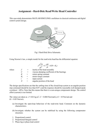
- 1. Assignment - Hard-Disk Read/Write Head Controller This case-study demonstrates MATLAB/SIMULINK's usefulness in classical continuous and digital control system design. Fig.1 Hard-Disk Drive Schematic Using Newton’s law, a simple model for the read/write head has the differential equation iKK dt d C dt d J i 2 2 where J = inertia of the head assembly C = viscous damping coefficient of the bearings K = return spring constant Ki = motor torque constant i = input current = angular position of the head The design specifications are that the settling time of the closed-loop system to an angular position step command should be less than 0.07 s and the response should be reasonably well damped (peak overshoot < 40%). Note that this means that there is a non-unique compensator design. The control effort (current) is not limited. The values are taken as J= 0.01 kg m2 , C = 0.004 Nm/(rad/s), K = 10 Nm/rad and Ki = 0.05 Nm/mA. (a) Investigate the open-loop behaviour of the read-write head. Comment on the dynamic characteristics. (b) Investigate whether the system can be stabilised by using the following compensator structures: 1. Proportional control 2. Proportional-Integral control 3. Phase-lag or phase-lead control
- 2. For (2), the controller has the structure, s asK sD )( )(2 . For (3), the controller has the structure, )( )( )(3 bs asK sD . It can be configured as a phase-lag or phase-lead controller depending on the values of a and b. The root-locus design method is useful in assessing the control structures and quick sketches can identify potential compensator designs. You may use any other control technique or design method that you are familiar with. Note numerical values for the compensator gain, pole and zero are not required at this stage. (c) Having established which control structure is the most useful, design the controller such that the system settles in about 70 ms with a peak overshoot of less than 40%. Note that the steady- state error problem is to be solved by placing a suitable scaling gain in series with the angular position reference input path. Test your controller by constructing a SIMULINK model of the closed-loop system. Does your compensator design produce the desired settling-time and peak overshoot figures? If not, suggest reason(s) as to why this is the case. (d) The peak overshoot problem can be addressed by adding velocity feedback as an inner control loop as part of the overall closed-loop system. The controller developed in part (c) is still to be used without further modification. The modification to the closed-loop system is shown in the diagram below (note that only the inner loop is shown). Determine the value of the derivative gain, kd,such that the velocity control loop exhibits a criticallydamped response using the root- locus. Include a plot that shows the new angular response of the read/write head with this inner loop included.
- 3. 2 Assignment – Hard-Disk Read/Write Head Controller Solution a. Simple model for the read/write head has the differential equation: 𝐽 𝑑2 𝜃 𝑑𝑡2 + 𝐶 𝑑𝜃 𝑑𝑡 + 𝐾𝜃 = 𝐾𝑖 𝑖 (1) 1. Taking Laplace transform of equation (1): 𝐽[𝑠2 𝜃(𝑠)] + 𝐶[𝑠𝜃(𝑠)] + 𝐾𝜃(𝑠) = 𝐾𝑖 𝐼(𝑠) (2) Therefore the transfer function from 𝑖 to 𝜃 is given by: 𝜃(𝑠) 𝐼(𝑠) = 𝐺(𝑠) = 𝐾𝑖 𝐽𝑠2 + 𝐶𝑠 + 𝐾 (3) Given that the values of variables of the transfer function are 𝐽 = 0.01 𝑘𝑔 𝑚2 , 𝐶 = 0.004 𝑁𝑚/(𝑟𝑎𝑑/𝑠) 𝐾 = 10 𝑁𝑚/𝑟𝑎𝑑 and 𝐾𝑖 = 0.05 𝑁𝑚/𝑚𝐴, the transfer function of the simple model is given by: 𝐺(𝑠) = 0.05 0.01𝑠2 + 0.004𝑠 + 10 (4) Dividing the numerator and denominator of equation (4) by 1 0.01 gives: 𝐺(𝑠) = 5 𝑠2 + 0.4𝑠 + 1000 (5) ∴ 𝐺(𝑠) = ( 1 200) × 1000 𝑠2 + 0.4𝑠 + 100 ∴ 𝐺(𝑠) = 𝐴 × 1000 𝑠2 + 0.4𝑠 + 1000 Where A = arbitrary constant
- 4. 3 2. Computation of Time Domain Parameters: a) Damping ratio (ζ) and undamped natural frequency (𝜔 𝑛) is computed as follows by comparing denominator of the transfer function equation (4) with equation (8) which represents standard form of second order transfer function. 𝐺(𝑠) = 𝜔 𝑛 2 𝑠2 + 2ζωn 𝑠 + 𝜔 𝑛 2 (8) Undamped frequency (𝜔 𝑛) is computed as: 𝜔 𝑛 2 = 1000 𝜔 𝑛 = √1000 = 31.622 𝑟𝑎𝑑/𝑠 Damping ratio is calculated as: 2ζωn = 0.4 2 × ζ × 31.622 = 0.4 ∴ ζ = 0.4 2 × 31.622 = 6.324 × 10⁻³ b) %Overshoot (%𝑀 𝑃) is given by the equation: %𝑀 𝑝 = 100𝑒 − 𝜋ζ √1−ζ2 (9) ∴ %𝑀 𝑝 = 100𝑒 − 𝜋×6.324×10⁻³ √(1−(6.324×10⁻³)2) ∴ %𝑀 𝑝 = 100𝑒− 0.019869 0.99998 ∴ %𝑀 𝑝 = 100𝑒−0.019872 ∴ %𝑀 𝑝 = 98.032%
- 5. 4 c) Settling time is given by the equation (within 2% after 4 time constants): 𝑇𝑠 = 4 ζωn (10) ∴ 𝑇𝑠 = 4 6.324 × 10−3 × 31.622 = 20𝑠 d) Peak time is given by the formula: 𝑇𝑝 = 𝜋 𝜔 𝑛√1 − ζ2 (11) ∴ 𝑇𝑝 = 𝜋 ((31.622) × √(1 − (6.324 × 10⁻³)2)) ∴ 𝑇𝑝 = 0.0993𝑠 e) Steady state error of the open-loop system (𝑒𝑠𝑠): 𝐾 𝑝(𝑃𝑜𝑠𝑖𝑡𝑖𝑜𝑛 𝑐𝑜𝑛𝑠𝑡𝑎𝑛𝑡 𝑒𝑟𝑟𝑜𝑟) = 𝐿𝑡 𝑠→0 𝐺(𝑠) ∴ 𝐾 𝑝 = 𝐿𝑡 𝑠→0[ 5 𝑠2 + 0.4𝑠 + 1000 ] ∴ 𝐾 𝑝 = [ 5 0 + 0 + 1000 ] ∴ 𝐾 𝑝 = 5 × 10⁻³ ∴ 𝑒𝑠𝑠 = 1 1 + 𝐾 𝑝 = 1 1 + (5 × 10⁻³) = 0.995
- 6. 5 Hand calculations for the time domain parameters can be further verified by the usage of Matlab. Open-loop loop behavior of the system to be investigated via the code listed in figure 1. Figure 1: Code to investigate open-loop behavior Figure 2 shows the computed results after execution of the code listed in figure 1. Figure 2: Computed results for open-loop system
- 7. 6 Figure 3 shows the step response of the open-loop system computed using function step. Figure 3: Step response of the open-loop system Figure 4 shows the computed poles and zeros of the open-loop of system. Figure 4: Poles and Zeros of the OLTF Hence the Read/Write Head OLTF having complex poles.
- 8. 7 Figure 5 shows the Root locus of the Read/Write Head of open-loop system. Figure 5: Root Locus of the open-loop system From the step response in figure 3, it can be observed that the system oscillates which is quite noticeable. Main reason is that it have very low damping ratio. The poles have very low damping ratio and are near to the jw-axis. Also the open-loop system have very high %overshoot (%𝑀 𝑝) and the settling time (𝑡 𝑠). Therefore compensator is required to be designed such that to increase the damping ratio, reduce 𝑡 𝑠, steady state error 𝑒𝑠𝑠 and %𝑀 𝑝 and also to pull the poles more towards the left hand side of the s- plane in order to provide stability. Solution b. Sometimes open-loop systems have not be able to provide the output. In order for the output to be determined by the system, it is very necessary for the systems to have feedback. The feedback also have the ability to sense when something goes wrong in the system and able to detect it. Hence the controller/compensator will be placed in series with main Read/Write Head in a closed-loop system with a unity negative feedback. From the root locus diagram in figure 5, it can be noticed that though the complex poles are in the left hand side of the s – plane diagram, it is very near to the imaginary axis and is likely to get unstable. Therefore to provide more stability to the system, three types of compensators will be investigated and is to be chosen for designing of the controller of the given system as follows: 1. Proportional Control: The proportional controller is placed in series with the Read/Write transfer function obtained in previous section within a closed loop unity negative feedback shown in figure 6.
- 9. 8 Figure 6: Closed loop system with Proportional controller Value for Proportional Controller K is chosen as 4. The system implemented in Matlab listed as code in figure 7. Figure 7: Implementation of Proportional controller for Read/Write head Root locus of the system is shown in figure 8 and the step response of the closed loop system with unity feedback as shown in figure 9.
- 10. 9 Figure 8: Root locus of the system after P controller implementation Figure 9: Step Response for closed loop system with Proportional Controller As it can be noticed from the root locus figures 5 and figure 8, it have neither pushed away from left hand side of the s – plane nor pulled towards right hand side of the s - plane. Also, it did not have any effect on the settling time. It did reduce the no. of oscillations for given period of time and the rise time has increased from 0.0331s to 0.0512s. The %overshoot is approximately the same as the original Read/Write Head. So the proportional controller hardly improves the stability or the step response of the system. Sometimes, very
- 11. 10 high gain of the proportional controller may cause the system to go unstable. Therefore a proportional controller is not suitable for stabilizing the Read/Write head system. 2. Proportional Integral Control: As the name itself suggest, the output is directly proportional to the integral of the error signal. Its transfer function is given by the following equation: 𝐷2(𝑠) = 𝐾(𝑠 + 𝑎) 𝑠 (12) To know whether or not proportional Integral will allow the system to stabilize, following implementation as code made in Matlab: Figure 9: Code to investigate PI compensator Value for K is same as previously implemented system i.e. K = 4 and value for zero i.e. the ‘a’ variable is set to 2.
- 12. 11 Root locus of the system after implementing PI compensator shown in figure 10. Figure 10: Root locus of the system to investigate PI compensation Step response of the closed loop system after implementation of PI compensator shown in figure 11. Figure 11: Step Response for closed loop system to investigate PI compensation
- 13. 12 From figure 10, it can be observed from the root locus diagram, it is a marginally stable system, as there is a pole exactly at the origin. There are complex poles and a zero the LHS of the s – plane. In the closed loop the system, the PI controller allowed the rise time to drastically increase from 0.0512s to 3.8s which will cause the undamped frequency(𝜔 𝑛) to decrease by sufficient amount, allowing poles to be on the left hand side of the s – plane and also %Mp dropped to 9.7%. But this implementation has caused the settling time to increase from 19.5s to 68s thus the steady state error for the PI controller implementation tends to exist for longer time than the system implemented with only Proportional Controller. But from the root locus diagram, it is observed that when gain K goes to infinity, it is pulled more towards the right hand side of the s- plane, hence causing the system to go unstable. 2. Phase lag control: In the phase lag control, the poles and zeros are placed very close to each other. And it’s combination is pretty close to the origin of the s-plane. Therefore, the root loci of the compensated system are shifted only slightly from original location. Its’ structure is given by the equation: 𝐷3 = 𝐾(𝑠 + 𝑎) (𝑠 + 𝑏) 𝑤ℎ𝑒𝑟𝑒 𝑎 > 𝑏 (13) Value for K and a are set to be the same as of previous implementation of the controllers. Pole is taken as 1 i.e. b = 1. The code for implementation of phase lag controller with the system shown in figure 12. Figure 12: Code to investigate Phase lag compensator
- 14. 13 The root locus of the system after the phase lag controller implementation shown in figure 13 and the step response of the system in figure 14. Figure 13: Root locus of the system to investigate compensation by phase lag controller Figure 14: Step response of the system to investigate compensation by phase lag controller
- 15. 14 The root locus of the system after phase lag implementation is approximately the same as that of the system that is implemented with proportional integral controller. The increase in rise time 𝑡 𝑟 is not as much as that of integral controller. Therefore undamped natural frequency 𝜔 𝑛 is higher than integral controller that will cause the poles to pull more towards the right hand side of the s - plane in comparison with the integral controller as the root loci tends to go to the right side of s-plane. There has been reduction in the settling time and hence have less steady state error for phase lag controller implemented system than the proportional integral controller implemented system. The %Mp has raised due to the decrease in settling time as a trade off. 3. Phase lead control: The phase lead network contributes a positive angle to the root locus criterion and tends to shift root locus of a system towards the left hand side of the s-plane. Its structure is exactly the same as of phase lag controller represented by equation 13 but poles are greater than zeros i.e. a<b. The code implementation of a phase lead controller shown in figure 15. Compensator gain and pole value are kept same as that of previously implemented controllers. Zero value is changed to 6 i.e. b = 6. Figure 15: Code to investigate compensation by phase lead controller Root locus and step response of the system after phase lead controller implementation shown in figure 16 and 17.
- 16. 15 Figure 16: Root locus of the system after phase lead controller implementation Figure 17: Step response of the system after phase lead controller implementation From root locus diagrams, it is observed that the phase lead controller allows the system to add more stability than the previous implementation of the controllers. As gain K goes to infinity, the poles goes more towards the left hand side of the s- plane therefore bring the system more into a stable region. Also comparing from the step response figures 11, 14 and 17, the rise time (𝑡 𝑟) is lower than that of the phase lag and PI controller. Therefore, phase lead controller will have higher undamped natural frequency 𝜔 𝑛
- 17. 16 than phase lag and PI controllers. This will cause to move more further away from the right hand side and pulled more towards the left hand side of the s-plane thus adding stability to the system. After investigation from the root locus diagrams, it can be concluded phase lead adds the most stability to the system in comparison than phase lag, PI and P controllers. Hence phase lead compensator will be chosen for the design which will be done in the next section of this assignment. Solution 3. Given that OLTF 𝐺(𝑠) = 5 𝑠2+0.4𝑠+1,000 %𝑀 𝑝 = 31.3% and 𝑡 𝑠 = 0.046𝑠 1. Find the damping ratio (𝜁) from equation: %Mp = 100𝑒 − 𝜋 𝜁 √(1− 𝜁2) (14) ∴ 31.3 = 100𝑒 − 𝜋 𝜁 √(1− 𝜁2) ∴ 0.313 = 𝑒 − 𝜋 𝜁 √(1− 𝜁2) Multiplying the equation by ln on both LHS and RHS: ∴ ln 0.313 = ln 𝑒 − 𝜋 𝜁 √(1− 𝜁2) ∴ −1.1616 = − 𝜋𝜁 √1 − 𝜁2 ∴ (1.1616)2 ( 𝜋𝜁 √1 − 𝜁2 ) 2 ∴ 1.3492 = 𝜋2 𝜁2 1−𝜁2
- 18. 17 ∴ 0.1367 × (1 − 𝜁2 ) = 𝜁2 ∴ 0.1367 − 0.1367𝜁2 = 𝜁2 ∴ 𝜁2 + 0.1367𝜁2 = 0.1367 ∴ 1.1367𝜁2 = 0.1367 ∴ 𝜁2 = 0.1367 1.1367 = 0.12026 ∴ 𝜁 = √0.12026 = 0.34679 2. Undamped natural frequency (𝜔 𝑛): 𝜔 𝑛 = 4 𝜁𝑡 𝑠 = 4 0.34679 × 0.046 = 250.7469 𝑟𝑎𝑑/𝑠 3. Dominant poles: 𝑠 𝑑 = −𝜁𝜔 𝑛 ± 𝑗𝜔 𝑛√1 − 𝜁2 𝑠 𝑑 = −0.34679 × 250.7469 ± 𝑗250.7469 × (√(1 − 0.346792) ) 𝑠 𝑑 = −0.34679 × 250.7469 ± 𝑗250.7469 × (√(1 − 0.346792) ) 𝑠 𝑑 = −86.9565 ± 𝑗250.7469 × (0.93794 ) 𝑠 𝑑 = −86.9565 ± 𝑗235.1855 Note: Diagram and more workings are done in the attached sheet paper in the end of the assignment.
- 19. 18 4. Angle of departure: 𝜃 𝑝1 = 180 𝑜 − 𝜃1 ′ 𝜃 𝑝1 = 180 𝑜 − tan−1 ( 203.5635 86.7565 ) 𝜃 𝑝1 = 113.08 𝑜 𝜃 𝑝2 = 180 𝑜 − 𝜃2 ′ 𝜃 𝑝2 = 180 𝑜 − tan−1 ( 266.8075 86.7565 ) 𝜃 𝑝2 = 108.01 𝑜 According to the angle criteria: 180 𝑜 − (𝜃 𝑝1 + 𝜃 𝑝2 + 𝜃 𝑏) + 𝜃 𝑎 = 0 Let 𝜃 𝑎 = 600 𝜃 𝑏 = 180 𝑜 − 113.08 𝑜 − 108.01 𝑜 + 60 𝑜 𝜃 𝑏 = 18.91 𝑜 To find a: tan 𝜃 𝑎 = 235.1855 𝑥 ∴ 𝑥 = 235.1855 tan 60 𝑜 = 135.784 ∴ 𝑎 = 135.784 + 86.9565 = 222.74 To find b: tan 𝜃 𝑏 = 235.1855 𝑦
- 20. 19 𝑦 = 235.1855 tan 18.91 𝑜 = 686.530 𝑏 = 686.530 + 86.9565 = 773.486 From magnitude criteria: 5𝐾𝑐 𝑙4 𝑙1 𝑙2 𝑙3 = 1 𝑙1 = √(86.75652 + 203.56352) = 221.280 𝑙2 = √(86.75652 + 266.80752) = 280.558 𝑙4 = √(135.7842 + 235.18552) = 271.569 𝑙3 = √(686.5302 + 235.18552) = 725.697 𝐾𝑐 = 𝑙1 𝑙2 𝑙3 5𝑙4 = 221.280 × 280.558 × 725.697 5 × 271.569 𝐾𝑐 = 33,179.46 Compensator or controller transfer function = 𝐺𝑐(𝑠) = 𝐾𝑐(𝑠+𝑎) (𝑠+𝑏) = 33,179.46 [ 𝑠+222.74 𝑠+773.486 ] Manually computed variables of the compensator are then directly used in Matlab for proper phase lead compensated closed loop system as shown in figure 18.
- 21. 20 Figure 18: Code listing for the final CLTF Hence, compensated OLTF of the system is given as: 𝑂𝐿𝑇𝐹 = 𝐺𝑐(𝑠)𝐺(𝑠) = 𝐾𝑐(𝑠 + 𝑎) (𝑠 + 𝑏) [ 5 𝑠2 + 0.4𝑠 + 1000 ] ∴ 𝑂𝐿𝑇𝐹 = 𝐺𝑐(𝑠)𝐺(𝑠) = 33,179.46 × (𝑠 + 222.74) (𝑠 + 773.486) × [ 5 𝑠2 + 0.4𝑠 + 1000 ] ∴ 𝐺𝑐(𝑠)𝐺(𝑠) = 165,897𝑠 + 36,952,120 𝑠3 + 773.9𝑠2 + 1,390𝑠 + 773,486
- 22. 21 Hence CLTF after the compensation of the system as given as (Computed from Matlab directly): 𝐶𝐿𝑇𝐹 = 165,897𝑠 + 36,952,120 𝑠3 + 773.9𝑠2 + 167,200𝑠 + 37,730,000 The root locus of the compensated OLTF is shown in figure 19. Figure 19: Root locus of compensated system by Phase Lead controller Time domain parameters computed via Matlab for the closed loop transfer function (CLTF) after the compensation of the system listed in figure 20. Figure 20: Computed Time domain parameters of CLTF after compensation
- 23. 22 The step response of the CLTF after designing followed by implementation of the compensator in the forward path of the system shown in figure 20. Figure 21: Step response of the closed loop system after compensation The designed controller is also tested by modelling it in SIMULINK. Therefore model in SIMULINK is created for the closed loop compensated system as shown in figure 22. Figure 22: Simulink model of the compensated closed loop system Firstly, the step time of the step input has to be changed from 1 to 0.0001s for the system to exhibit transient response. Simulation for the system is run for 0.07s. The step response of the Simulink model for the compensated CLTF obtained from scope shown in figure 17.
- 24. 23 Figure 23: Step response obtained from Simulink model of compensated CLTF From the step response of the compensated closed loop system both in figure 21(step response obtained via Matlab) and figure 22(obtained via simulation from Scope), it can be notice there is still steady state error. In order to reduce steady state error of the CLTF system, suitable scaling gain is to be place in series with the step input with the angular position reference input. Since step input will be used as input, sum of unity gain and 𝑒𝑠𝑠 value will be used as suitable gain 𝐾𝑒. Steady state error after compensation of the system is computed as follows: Since input will be used as step input, position error constant (𝐾 𝑝) is calculated: 𝐾 𝑝 = 𝐿𝑡 𝑠→0 𝑂𝐿𝑇𝐹 𝐾 𝑝 = 𝐿𝑡 𝑠→0(33,179.46 × (𝑠 + 222.74) (𝑠 + 773.486) × [ 5 𝑠2 + 0.4𝑠 + 1000 ]) ∴ 𝐾 𝑝 = 𝐿𝑡 𝑠→0(33,179.46 × (0 + 222.74) (0 + 773.486) × [ 5 0 + 0 + 1000 ]) ∴ 𝐾 𝑝 = 47.77 ∴ 𝑒𝑠𝑠 = 1 1 + 47.77 = 0.0205 Hence value of 𝐾𝑒 computed as: 𝐾𝑒 = 1 + 0.0205 = 1.0205
- 25. 24 The model of the compensated system after addition of the suitable gain 𝐾𝑒 in series to the angular position to input path, that allowed to reduce steady state error shown in figure 24 and its step response shown in figure 25. Figure 24: Model of the system after reduction of steady state error Figure 25: Step response of the system after elimination of steady state error Initial chosen value for settling time of the closed loop system was 𝑡 𝑠 = 0.046𝑠. After completion of designing the controller, from the results of stepinfo command applied on CLTF, the settling time is obtained as 𝑡 𝑠 = 0.0429𝑠. There is very small difference between the initial and final settling times. Also it can be observed from figures 15 and 17, from these step responses the settling time 𝑡 𝑠 is 0.0429s. Hence approximately desired settling time 𝑡 𝑠 is obtained. The steady error which initially existed in the compensated closed loop system is also successfully reduced by addition of the suitable gain scale as it can be observed from the step response in figure 25 by comparing it with step response in figure 23. Steady state error at 0.05s in figure 23 is approximately 0.021 and in figure 25 it is approximately 0. But the design did not meet the %overshoot requirement as theoretically chosen %𝑀 𝑝 = 31.3% and the output step
- 26. 25 response %𝑀 𝑝 = 51.0363%. The %overshoot is high due to the tradeoff made by the controller, preferring the settling time (𝑡 𝑠) over the %overshoot. Since low settling time 𝑡 𝑠 is required, it will cause the damping ratio to be less. This will cause %overshoot to be more. It is not easy task to get perfect balance between these two time domain parameters though numerous designs can be implemented to overcome the %𝑀 𝑝 issue. This problem will be addressed and overcome in the next section of the assignment. Solution d. The code implemented to obtain root locus for the new open-loop system as per the given question shown in figure 26. Figure 26: Code to generate root locus for new OLTF The root locus for new open-loop system shown in figure 27.
- 27. 26 Figure 27: Root locus of new open-loop system For the velocity control loop to exhibit a critically damped response, since condition for it has to be the damping ratio is 1, pole = -1 is selected at the root locus diagram in order to obtain the value for derivative gain 𝐾 𝑑. Hence 𝐾 𝑑 = 198 for velocity control loop to exhibit critically damped response. Simulink model for the new system that includes velocity control loop that will overcome the peak overshoot issue is shown in figure 28. Figure 28: New model of the system where peak overshoot issue is eliminated The critically damped transient response exhibited by the new system is observed from the graph obtained
- 28. 27 from scope is shown in figure 29. It is the new angular response of the read/write head with the inner loop included. It can be noticed from the figure 29, peak overshoot issue is completely nullified. Figure 29: Critically damped transient response exhibited by the new system.