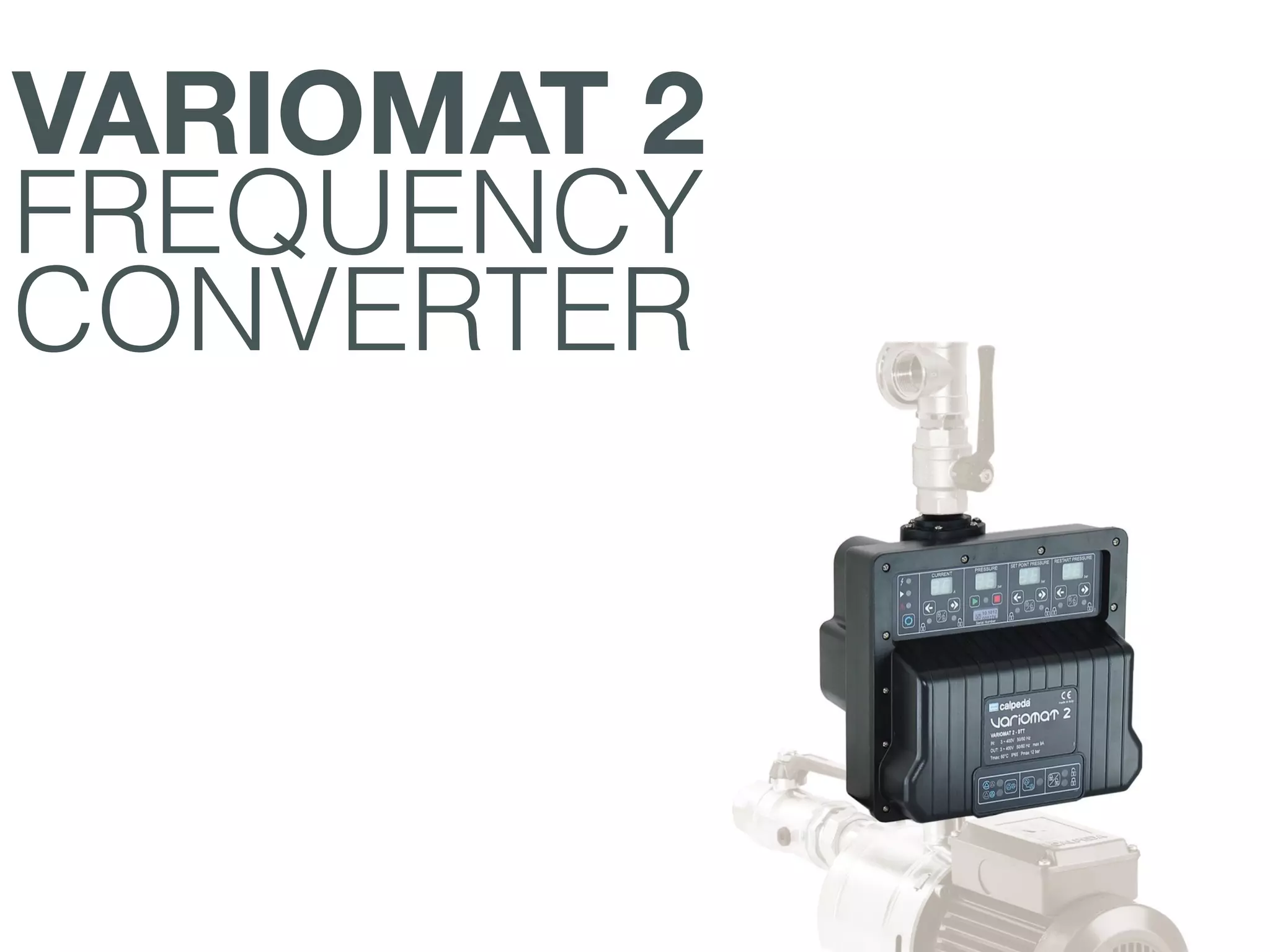
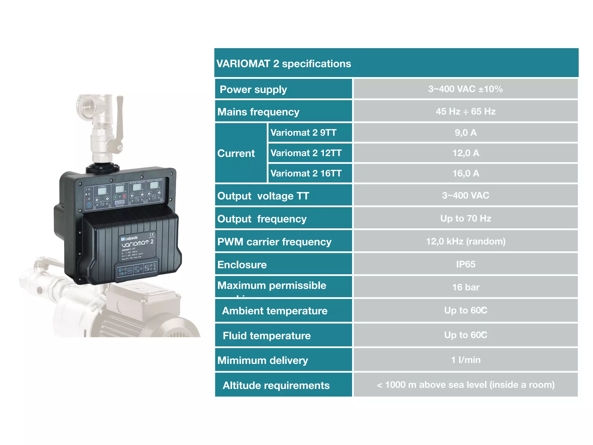
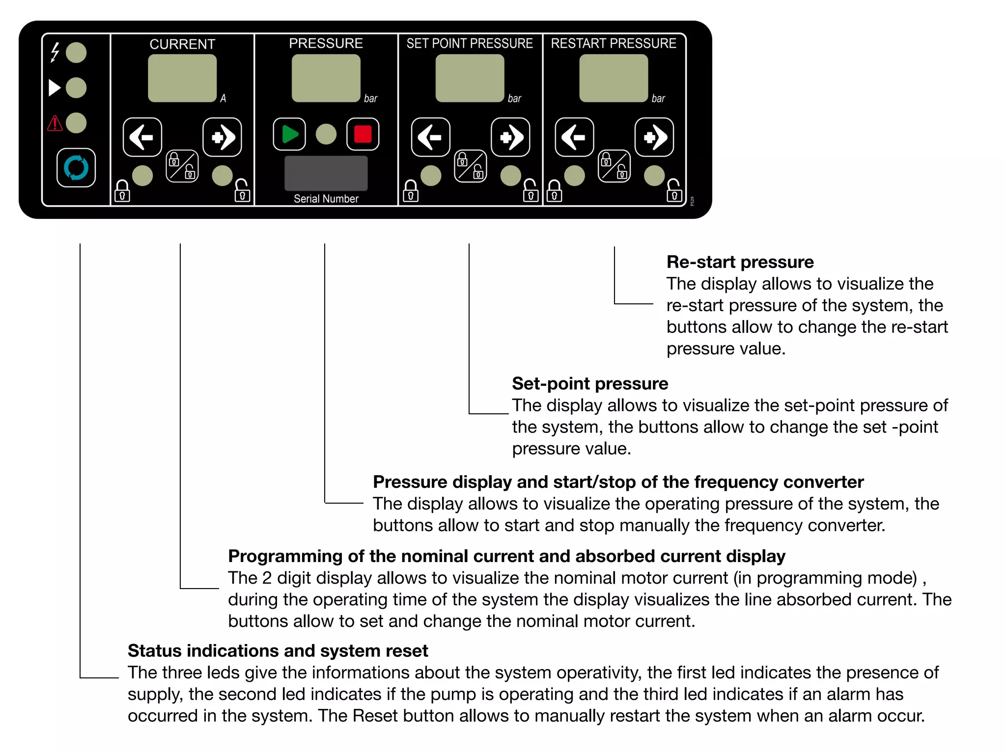
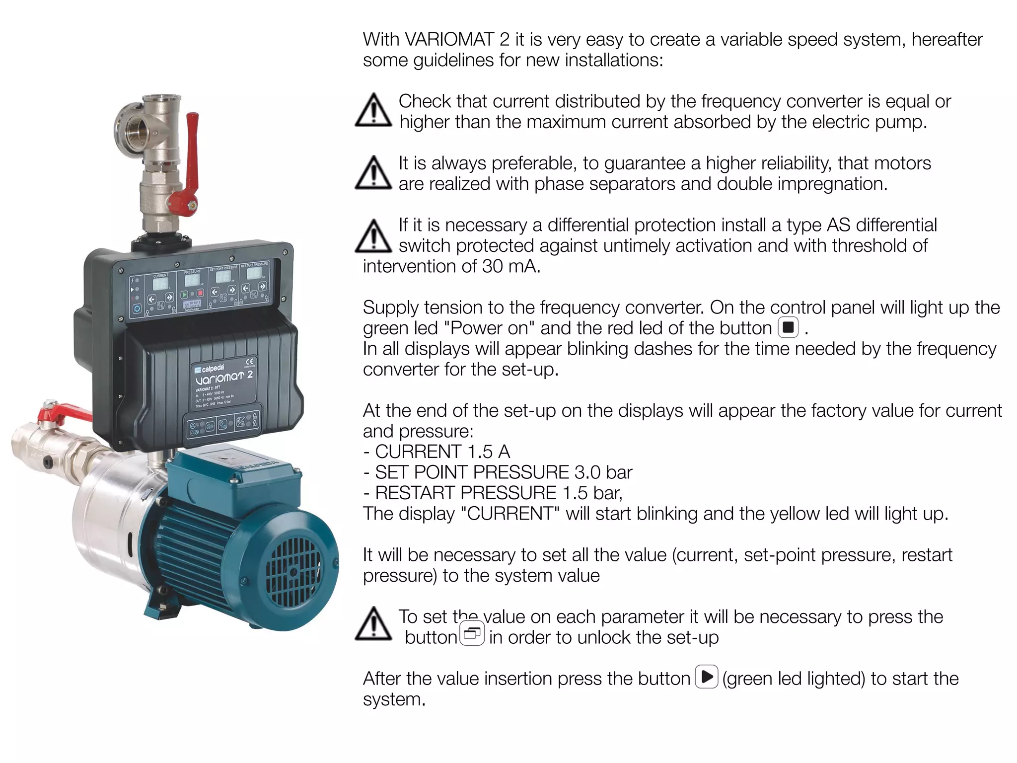
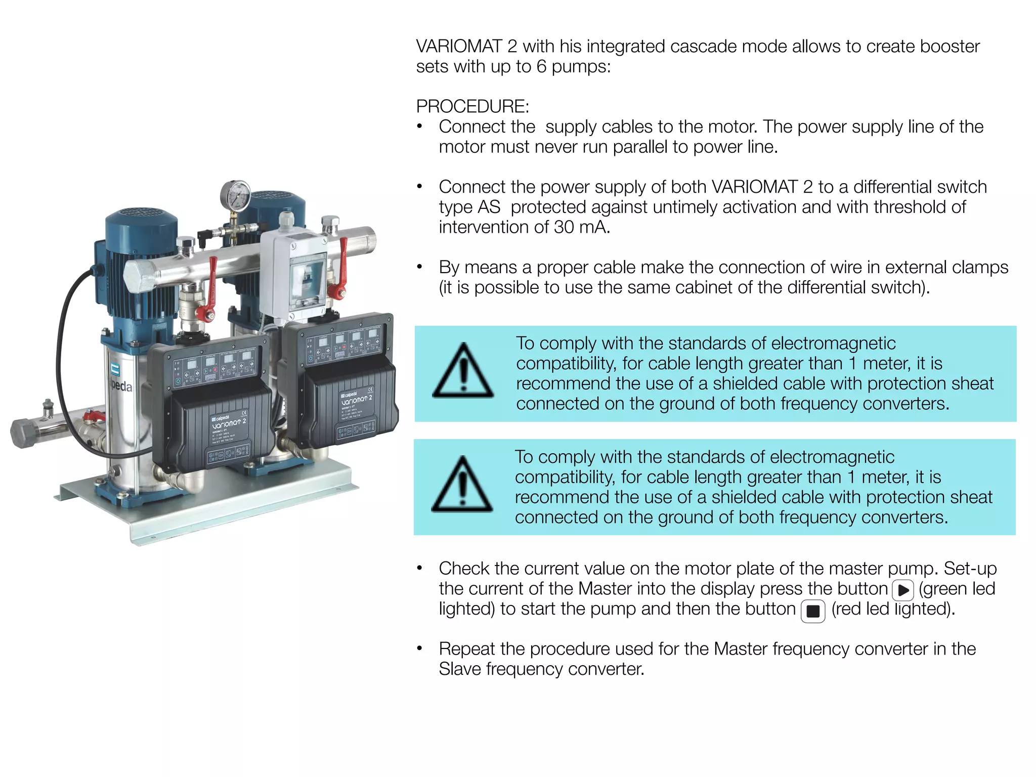
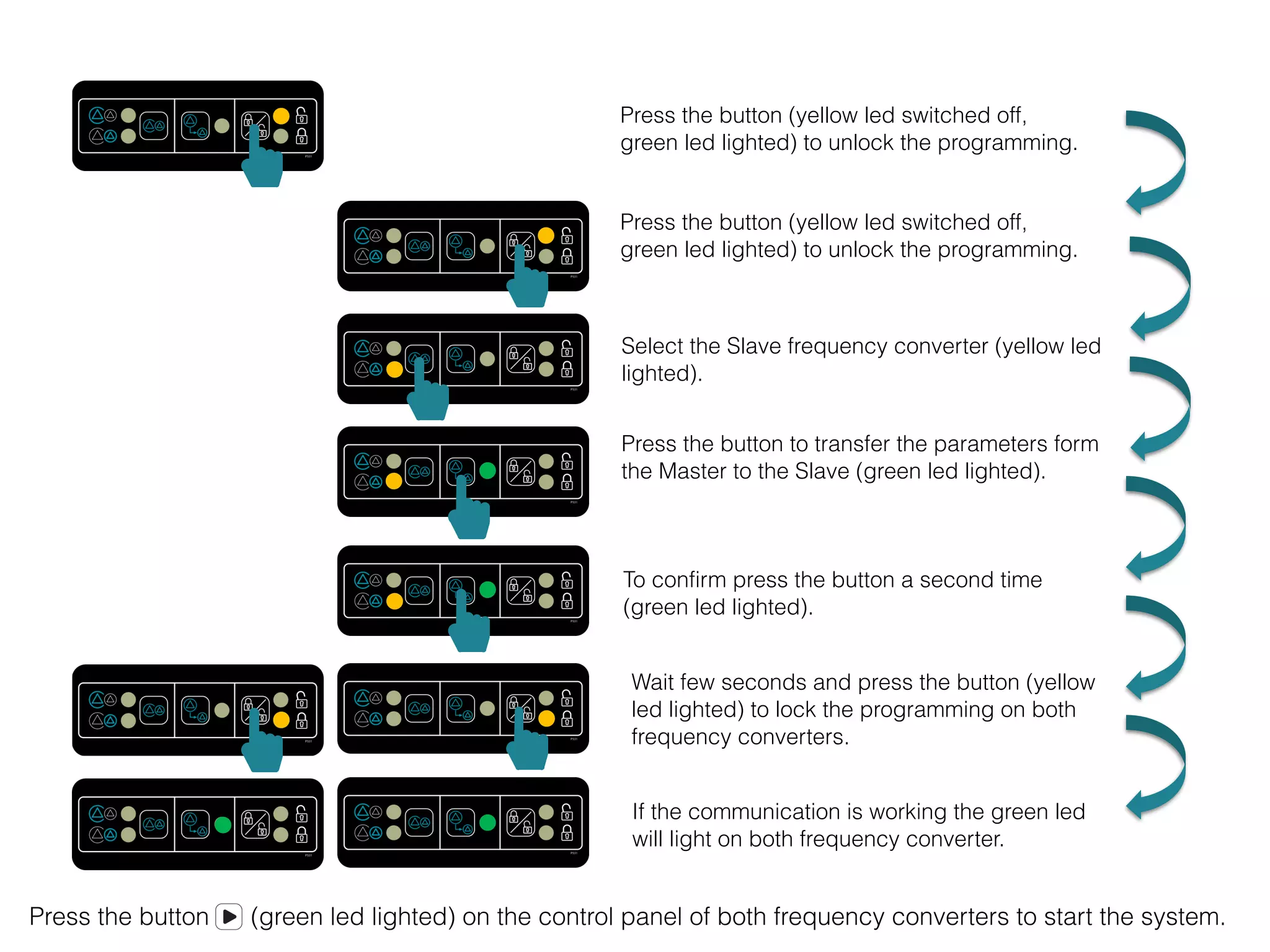
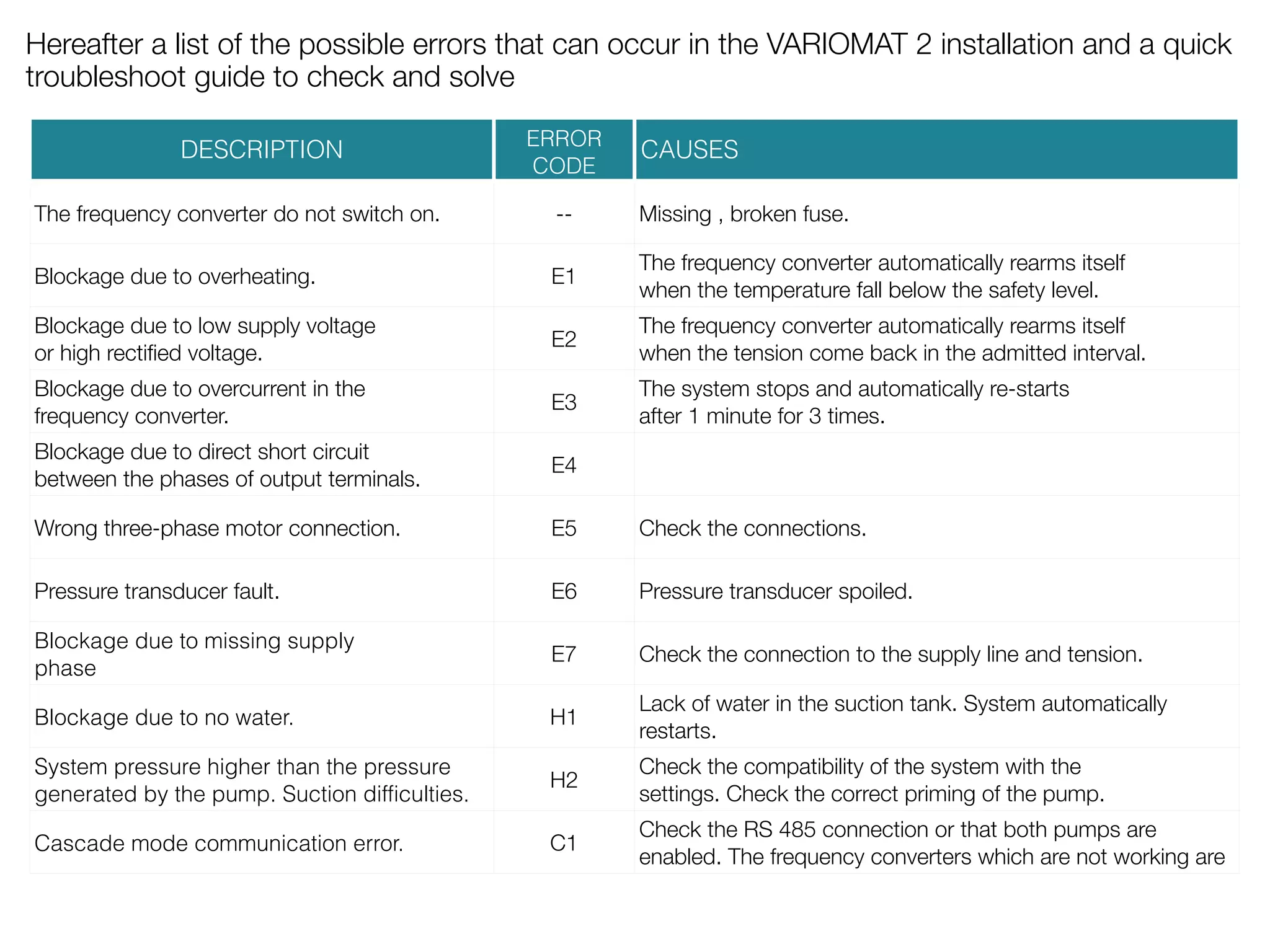
A training presentation to explain how to use the Calpeda VARIOMAT2,
VARIOMAT Construction:
Variable speed system driven by frequency converter, for the pressure control in domestic and residential plants.The unit more compact and easy to assemble. VARIOMAT2 is supplied with one pressure transducer, G 1/4 connection and 1.5 m cable length.
Application:
Automatic frequency inverter control for use on pumps to increase network pressure. The system maintains constant pressure whilst the controlling the pump operation against changing system demand.
For protection of the pumps: against dry running, against operations with closed connection ports, against overcurrent of the motor, against overvoltage and undervoltage of the power supply
4. VARIOMAT 2 specifications
Power supply 3~400 VAC ±10%
Mains frequency 45 Hz ÷ 65 Hz
Current
Variomat 2 9TT 9,0 A
Variomat 2 12TT 12,0 A
Variomat 2 16TT 16,0 A
Output voltage TT 3~400 VAC
Output frequency Up to 70 Hz
PWM carrier frequency 12,0 kHz (random)
Enclosure IP65
Maximum permissible
16 bar
working pressure
Ambient temperature Up to 60°C
Fluid temperature Up to 60°C
Mimimum delivery 1 l/min
Altitude requirements < 1000 m above sea level (inside a room)
6. Re-start pressure
The display allows to visualize the
re-start pressure of the system, the
buttons allow to change the re-start
pressure value.
Set-point pressure
The display allows to visualize the set-point pressure of
the system, the buttons allow to change the set -point
pressure value.
Pressure display and start/stop of the frequency converter
The display allows to visualize the operating pressure of the system, the
buttons allow to start and stop manually the frequency converter.
Programming of the nominal current and absorbed current display
The 2 digit display allows to visualize the nominal motor current (in programming mode) ,
during the operating time of the system the display visualizes the line absorbed current. The
buttons allow to set and change the nominal motor current.
Status indications and system reset
The three leds give the informations about the system operativity, the first led indicates the presence of
supply, the second led indicates if the pump is operating and the third led indicates if an alarm has
occurred in the system. The Reset button allows to manually restart the system when an alarm occur.
8. With VARIOMAT 2 it is very easy to create a variable speed system, hereafter
some guidelines for new installations:
Check that current distributed by the frequency converter is equal or
higher than the maximum current absorbed by the electric pump.
It is always preferable, to guarantee a higher reliability, that motors
are realized with phase separators and double impregnation.
If it is necessary a differential protection install a type AS differential
switch protected against untimely activation and with threshold of
intervention of 30 mA.
Supply tension to the frequency converter. On the control panel will light up the
green led "Power on" and the red led of the button .
In all displays will appear blinking dashes for the time needed by the frequency
converter for the set-up.
At the end of the set-up on the displays will appear the factory value for current
and pressure:
- CURRENT 1.5 A
- SET POINT PRESSURE 3.0 bar
- RESTART PRESSURE 1.5 bar,
The display "CURRENT" will start blinking and the yellow led will light up.
It will be necessary to set all the value (current, set-point pressure, restart
pressure) to the system value
To set the value on each parameter it will be necessary to press the
button in order to unlock the set-up
After the value insertion press the button (green led lighted) to start the
system.
10. VARIOMAT 2 with his integrated cascade mode allows to create booster
sets with up to 6 pumps:
PROCEDURE:
• Connect the supply cables to the motor. The power supply line of the
motor must never run parallel to power line.
• Connect the power supply of both VARIOMAT 2 to a differential switch
type AS protected against untimely activation and with threshold of
intervention of 30 mA.
• By means a proper cable make the connection of wire in external clamps
(it is possible to use the same cabinet of the differential switch).
To comply with the standards of electromagnetic
compatibility, for cable length greater than 1 meter, it is
recommend the use of a shielded cable with protection sheat
connected on the ground of both frequency converters.
To comply with the standards of electromagnetic
compatibility, for cable length greater than 1 meter, it is
recommend the use of a shielded cable with protection sheat
connected on the ground of both frequency converters.
• Check the current value on the motor plate of the master pump. Set-up
the current of the Master into the display press the button (green led
lighted) to start the pump and then the button (red led lighted).
• Repeat the procedure used for the Master frequency converter in the
Slave frequency converter.
11. Press the button (yellow led switched off,
green led lighted) to unlock the programming.
Press the button (yellow led switched off,
green led lighted) to unlock the programming.
Select the Slave frequency converter (yellow led
lighted).
Press the button to transfer the parameters form
the Master to the Slave (green led lighted).
To confirm press the button a second time
(green led lighted).
Wait few seconds and press the button (yellow
led lighted) to lock the programming on both
frequency converters.
If the communication is working the green led
will light on both frequency converter.
Press the button (green led lighted) on the control panel of both frequency converters to start the system.
13. Hereafter a list of the possible errors that can occur in the VARIOMAT 2 installation and a quick
troubleshoot guide to check and solve
DESCRIPTION ERROR
CODE
CAUSES
The frequency converter do not switch on. -- Missing , broken fuse.
Blockage due to overheating. E1 The frequency converter automatically rearms itself
when the temperature fall below the safety level.
Blockage due to low supply voltage
or high rectified voltage. E2 The frequency converter automatically rearms itself
when the tension come back in the admitted interval.
Blockage due to overcurrent in the
frequency converter. E3 The system stops and automatically re-starts
after 1 minute for 3 times.
Blockage due to direct short circuit
between the phases of output terminals. E4
Wrong three-phase motor connection. E5 Check the connections.
Pressure transducer fault. E6 Pressure transducer spoiled.
Blockage due to missing supply
phase
E7 Check the connection to the supply line and tension.
Blockage due to no water. H1 Lack of water in the suction tank. System automatically
restarts.
System pressure higher than the pressure
generated by the pump. Suction difficulties.
H2 Check the compatibility of the system with the
settings. Check the correct priming of the pump.
Cascade mode communication error. C1 Check the RS 485 connection or that both pumps are
enabled. The frequency converters which are not working are
recognizable from the red led "Failure" blinking. The frequency