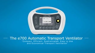
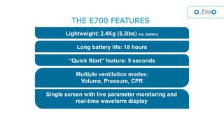
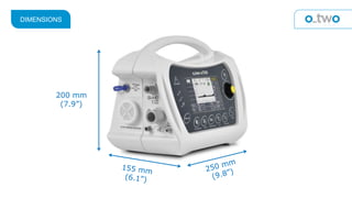
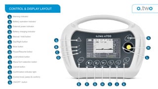
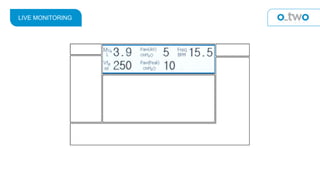
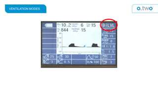
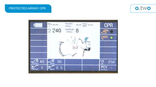
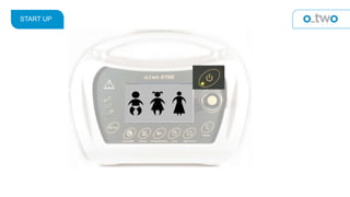
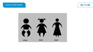
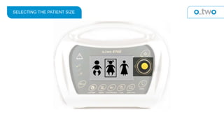
“ C o m p a c t , E ff i c i e n t , S o p h i s t i c a t e d , E a s y t o U s e
a n d E c o n o m i c a l Tr a n s p o r t Ve n t i l a t i o n ”
The e700 Automatic Transport Ventilator
Lightweight: 2.4Kg (5.3lbs) inc. battery
Long battery life: 18 hours
“Quick Start” feature: 5 seconds
Multiple ventilation modes:
Volume, Pressure, CPR
Single screen with live parameter monitoring and
real-time waveform display
THE E700 FEATURES
200 mm
(7.9”)
DIMENSIONS
PREPARATION FOR USE
ELECTRONIC VENTILATOR PATIENT CIRCUIT
Non-woven
Fabric Cover
VENTILATOR CIRCUIT COMPONENTS
15/22mm
patient
connection
Pneumotach
Sensor
Mushroom Valve
Assembly
Air intake
22mm Tubing
Sensor Lines
EXTERNAL CONNECTIONS
A DC Input connector
B
Air Intake filterC
Sensor connector #1
D
Sensor connector #2
E
22mm gas output connector
F
Gas supply input
A
B
C
D
E
F
Ensure that your gas supply hose is connected (P) and attached to a regulated
medical oxygen gas supply (as required in the specifications).
Attach the O-Two Electronic Ventilator Circuit to output connector (R)
Note: Only use approved O-Two ventilator circuits.
Connect the monitoring hoses to the appropriate sensor connectors (S & T)
Ensure that an air intake filter (Q) is in place.
INSTALLING/REPLACING THE BATTERY
Screw knob
Battery stand off
Positioned upwards
INSTALLING/REPLACING THE BATTERY
Make sure the ventilator is turned off and unplugged from mains electrical
supply.
Turn screw knob on battery compartment cover anticlockwise to loosen cover
downwards.
Disconnect the battery leads and pull out the battery pack using its stand off.
Never pull the battery pack by its leads.
Insert the fully charged battery such that the battery stand off is positioned
upwards, attach battery connectors. Close cover and turn screw knob clock wise
to secure.
1
2
3
4
Control & Display Layout
CONTROL & DISPLAY LAYOUT
A Warning Indicator
B Battery operation indicator
C External power indicator
D Battery charging indicator
E Manual / hold button
F Day/Night button
G Mute button
H Pause/Resume button
I Lock/Unlock button
J Wave form selection button
K Cancel button
L Confirmation indicator light
M Control knob (select & confirm)
N ON/OFF button
B
C
D
E F G H I J K
L
M
N
A
KEY MEMBRANE CONTROLS
Manual/Inspiratory Hold (Manual)
During exhalation phase, if Manual Button (E) is pressed, a mandatory breath will be
initiated and either the flow rate or set pressure control parameter will be delivered
as long as the manual button is pressed or until I-time setting is achieved.
After I-time if manual button still pressed, the ventilator will switch to inspiratory hold
function in which the ventilator will cut the flow but will keep the exhalation port
closed in order to block exhaled gas from going to ambient resulting in maintaining
lung pressure.
The maximum inspiratory hold time is 6 seconds, after that time, the ventilator will
switch to exhalation phase by opening airway pressure to ambient. All modes except
CPAP and CPR have Manual function.
Day/Night
Pressing Day/Night button (F) will change the text, waveform and background colors to
achieve higher or lower contrast and brightness . There are only 2 modes as following:
Light background with dark text and waveform for day mode.
Dark background with light color text and waveform for night mode. In this mode all
buttons and label information will be illuminated
Mute
Pressing the Mute button (G) will silence audible alarms for 2 minutes. Mute can be also
selected when there is no alarm in order to silence potential alarms for 2 minutes. This
function is activated or deactivated by pressing the mute button once.
When selected, the mute symbol will be shown on the screen.
Pause/Resume
Depressing the Pause button (H), will stop ventilation with all buttons kept active (if
they were not locked) except MANUAL.
The Pause symbol will flash on the screen as well as the confirmation symbol in the
window along with the confirmation LED, to guide users to activate pause by
pressing the control knob.
The symbol will flash for 10 seconds and then disappear if confirmation is not
selected. Users can also press the cancel button (K) to quit this selection before 10
seconds.
Once activated, a flashing yellow pause symbol will be displayed on the screen and
ventilator will stop ventilation.
Lock
By pressing Lock Button (I), all buttons and control knob except ON/OFF, Mute and
Day/Night will be disabled. A Lock symbol will be displayed on the screen. To cancel
lock function, press the Lock Button again.
Waveform
Pressing Waveform Button (J) will switch between pressure and volume ventilation
waveform.
Cancel
The Cancel Button (K) allows the operator to return to the previous settings if last
unconfirmed changes in settings are not required.
Control Knob
The Control Knob (M) is used to select ventilator functions and parameters.
ON/OFF
The ON/OFF Button (N) turns the ventilator ON when held depressed for 1 second
and OFF when held for 4 seconds
CONTROL KNOB/CURSOR MOTION PATH
LED’S
POWER LED
CONFIRMATION LED
BATTERY POWER
MAINS POWER
BATTERY CHARGING
VISUAL ALARM
LEDS
Red or Yellow color LED – Flashing during warning situation. LED color depends on the
severity of the failure.
Display layout
VENTILATOR PARAMETER WINDOW
Section 1: Battery status during charge and discharge.
Section 2: Live ventilation parameters including:
(Vte, Mve, Paw peak, Paw AV, Freq.).
Section 3: Modes (A/ C V, SIMV, BiLVL, CPAP & CPR).
Section 4: Alarms/ Warnings.
Section 5: Ventilation wave forms.
Section 6: Set up parameters.
Section 7: Confirmation request or Patient effort or invalid
setting symbols.
BATTERY STATUS INDICATORS
BATTERY CHARGING STATUS “ON SCREEN” INDICATORS
BATTERY DISCHARGE STATUS “ON SCREEN” INDICATORS
LIVE MONITORING
2
VENTILATION MODES
ALARMS AND WARNINGS
ALARM SYMBOLS
ALARM SYMBOLS (cont’d)
WAVEFORM DISPLAY
VENTILATOR PARAMETER
A/C V (Assist Control Ventilation – volume or pressure)
Note: with the Trigger turned off (-) the mode becomes CMV
SIMV (Synchronous Intermittent Mandatory Ventilation – volume or pressure)
BiLVL (Bi-phasic Positive Airway Pressure)
CPAP (Continuous Positive Airway Pressure)
MASK VENTILATED CPR
PROTECTED AIRWAY CPR
START UP
QUICK START MODE
Infant Child Adult
SELECTING THE PATIENT SIZE
ADJUSTING VENTILATION MODES
3
CHANGING THE VENTILATION MODE
Rotate the cursor to highlight
the mode window and press
Press the rotary control to
select the desired mode1
2
3
Press again to
confirm the selection
ADJUSTMENT OF THE VENTILATION PARAMETERS
6
ADJUSTMENT OF THE VENTILATION PARAMETERS
Vt Set Tidal volume in ml
Freq. Ventilation frequency (number of breaths per minute)
Mv Set Minute volume
I:E Ratio of inspiration time to expiration time
Ti Inspiration time in seconds
PEEP Positive End Expiratory Pressure in cmH2O
PSV Pressure Support Ventilation in cmH2O
PCV Pressure control Ventilation
Trig. Triggering flow rate in L/min
F termin. Termination (% of Maximum flow value)
O2 (%) Percentage of Oxygen inspired
Mv (L) Minute volume high and low alarm levels measured in liters
cm H2O Airway pressure high and low alarm levels
or
PARAMETER ADJUSTMENT
Press the rotary control
to highlight parameter
Rotate the rotary control to place the
cursor around the desired parameter1
2
3
Rotate the rotary control to adjust the
parameter and press to select
4
Press the rotary control to
confirm the new setting
TROUBLE SHOOTING
O-Two eSeries e700 Ventilator fFunction and Operation

O-Two eSeries e700 Ventilator fFunction and Operation

  • 2.
    “ C om p a c t , E ff i c i e n t , S o p h i s t i c a t e d , E a s y t o U s e a n d E c o n o m i c a l Tr a n s p o r t Ve n t i l a t i o n ” The e700 Automatic Transport Ventilator
  • 3.
    Lightweight: 2.4Kg (5.3lbs)inc. battery Long battery life: 18 hours “Quick Start” feature: 5 seconds Multiple ventilation modes: Volume, Pressure, CPR Single screen with live parameter monitoring and real-time waveform display THE E700 FEATURES
  • 4.
  • 5.
  • 6.
    ELECTRONIC VENTILATOR PATIENTCIRCUIT Non-woven Fabric Cover
  • 7.
  • 8.
    EXTERNAL CONNECTIONS A DCInput connector B Air Intake filterC Sensor connector #1 D Sensor connector #2 E 22mm gas output connector F Gas supply input A B C D E F Ensure that your gas supply hose is connected (P) and attached to a regulated medical oxygen gas supply (as required in the specifications). Attach the O-Two Electronic Ventilator Circuit to output connector (R) Note: Only use approved O-Two ventilator circuits. Connect the monitoring hoses to the appropriate sensor connectors (S & T) Ensure that an air intake filter (Q) is in place.
  • 9.
    INSTALLING/REPLACING THE BATTERY Screwknob Battery stand off Positioned upwards
  • 10.
    INSTALLING/REPLACING THE BATTERY Makesure the ventilator is turned off and unplugged from mains electrical supply. Turn screw knob on battery compartment cover anticlockwise to loosen cover downwards. Disconnect the battery leads and pull out the battery pack using its stand off. Never pull the battery pack by its leads. Insert the fully charged battery such that the battery stand off is positioned upwards, attach battery connectors. Close cover and turn screw knob clock wise to secure. 1 2 3 4
  • 11.
  • 12.
    CONTROL & DISPLAYLAYOUT A Warning Indicator B Battery operation indicator C External power indicator D Battery charging indicator E Manual / hold button F Day/Night button G Mute button H Pause/Resume button I Lock/Unlock button J Wave form selection button K Cancel button L Confirmation indicator light M Control knob (select & confirm) N ON/OFF button B C D E F G H I J K L M N A
  • 13.
    KEY MEMBRANE CONTROLS Manual/InspiratoryHold (Manual) During exhalation phase, if Manual Button (E) is pressed, a mandatory breath will be initiated and either the flow rate or set pressure control parameter will be delivered as long as the manual button is pressed or until I-time setting is achieved. After I-time if manual button still pressed, the ventilator will switch to inspiratory hold function in which the ventilator will cut the flow but will keep the exhalation port closed in order to block exhaled gas from going to ambient resulting in maintaining lung pressure. The maximum inspiratory hold time is 6 seconds, after that time, the ventilator will switch to exhalation phase by opening airway pressure to ambient. All modes except CPAP and CPR have Manual function.
  • 14.
    Day/Night Pressing Day/Night button(F) will change the text, waveform and background colors to achieve higher or lower contrast and brightness . There are only 2 modes as following: Light background with dark text and waveform for day mode. Dark background with light color text and waveform for night mode. In this mode all buttons and label information will be illuminated Mute Pressing the Mute button (G) will silence audible alarms for 2 minutes. Mute can be also selected when there is no alarm in order to silence potential alarms for 2 minutes. This function is activated or deactivated by pressing the mute button once. When selected, the mute symbol will be shown on the screen.
  • 15.
    Pause/Resume Depressing the Pausebutton (H), will stop ventilation with all buttons kept active (if they were not locked) except MANUAL. The Pause symbol will flash on the screen as well as the confirmation symbol in the window along with the confirmation LED, to guide users to activate pause by pressing the control knob. The symbol will flash for 10 seconds and then disappear if confirmation is not selected. Users can also press the cancel button (K) to quit this selection before 10 seconds. Once activated, a flashing yellow pause symbol will be displayed on the screen and ventilator will stop ventilation. Lock By pressing Lock Button (I), all buttons and control knob except ON/OFF, Mute and Day/Night will be disabled. A Lock symbol will be displayed on the screen. To cancel lock function, press the Lock Button again.
  • 16.
    Waveform Pressing Waveform Button(J) will switch between pressure and volume ventilation waveform. Cancel The Cancel Button (K) allows the operator to return to the previous settings if last unconfirmed changes in settings are not required. Control Knob The Control Knob (M) is used to select ventilator functions and parameters. ON/OFF The ON/OFF Button (N) turns the ventilator ON when held depressed for 1 second and OFF when held for 4 seconds
  • 17.
  • 18.
    LED’S POWER LED CONFIRMATION LED BATTERYPOWER MAINS POWER BATTERY CHARGING VISUAL ALARM
  • 19.
    LEDS Red or Yellowcolor LED – Flashing during warning situation. LED color depends on the severity of the failure.
  • 20.
  • 21.
    VENTILATOR PARAMETER WINDOW Section1: Battery status during charge and discharge. Section 2: Live ventilation parameters including: (Vte, Mve, Paw peak, Paw AV, Freq.). Section 3: Modes (A/ C V, SIMV, BiLVL, CPAP & CPR). Section 4: Alarms/ Warnings. Section 5: Ventilation wave forms. Section 6: Set up parameters. Section 7: Confirmation request or Patient effort or invalid setting symbols.
  • 22.
  • 23.
    BATTERY CHARGING STATUS“ON SCREEN” INDICATORS
  • 24.
    BATTERY DISCHARGE STATUS“ON SCREEN” INDICATORS
  • 25.
  • 26.
  • 27.
  • 28.
  • 29.
  • 30.
  • 31.
  • 32.
    A/C V (AssistControl Ventilation – volume or pressure) Note: with the Trigger turned off (-) the mode becomes CMV
  • 33.
    SIMV (Synchronous IntermittentMandatory Ventilation – volume or pressure)
  • 34.
    BiLVL (Bi-phasic PositiveAirway Pressure)
  • 35.
    CPAP (Continuous PositiveAirway Pressure)
  • 36.
  • 37.
  • 38.
  • 39.
  • 40.
  • 41.
  • 42.
    CHANGING THE VENTILATIONMODE Rotate the cursor to highlight the mode window and press Press the rotary control to select the desired mode1 2 3 Press again to confirm the selection
  • 43.
    ADJUSTMENT OF THEVENTILATION PARAMETERS 6
  • 44.
    ADJUSTMENT OF THEVENTILATION PARAMETERS Vt Set Tidal volume in ml Freq. Ventilation frequency (number of breaths per minute) Mv Set Minute volume I:E Ratio of inspiration time to expiration time Ti Inspiration time in seconds PEEP Positive End Expiratory Pressure in cmH2O PSV Pressure Support Ventilation in cmH2O PCV Pressure control Ventilation Trig. Triggering flow rate in L/min F termin. Termination (% of Maximum flow value) O2 (%) Percentage of Oxygen inspired Mv (L) Minute volume high and low alarm levels measured in liters cm H2O Airway pressure high and low alarm levels or
  • 45.
    PARAMETER ADJUSTMENT Press therotary control to highlight parameter Rotate the rotary control to place the cursor around the desired parameter1 2 3 Rotate the rotary control to adjust the parameter and press to select 4 Press the rotary control to confirm the new setting
  • 46.