Download to read offline

![Product
introduction
CR-H, CRN-H, CRE-H, CRNE-H
1
9
Optional motors
The Grundfos standard range of motors covers a wide
variety of application demands. However, for special
applications or operating conditions, custom-built
motor solutions can be provided.
For special applications or operating conditions,
Grundfos offers custom-built motors such as:
• explosion-proof motors
• motors with anti-condensation heating unit
• low-noise motors
• energy efficient and premium efficiency motors
• motors with thermal protection.
Motor protection
Single-phase Grundfos specified motors up to 3/4 HP
have a built-in thermal overload switch.
Three-phase motors must be connected to a motor-
protective circuit breaker in accordance with local
regulations.
MLE motors
CRE-H, CRNE-H pumps require no external motor
protection. The MLE motor incorporates thermal
protection against slow overloading and blocking.
Terminal box positions
As standard the terminal box is mounted as shown in
fig. 6.
Fig. 6 Terminal box positions
Viscosity
The pumping of liquids with densities or kinematic
viscosities higher than those of water will cause a
considerable pressure drop, a drop in the hydraulic
performance and a rise in the power consumption.
In such situations, the pump must be equipped with a
larger motor. For selection you may utilize the
Grundfos Product Center at www.grundfos.com. If in
doubt, contact Grundfos.
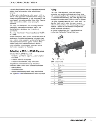
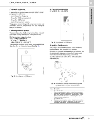
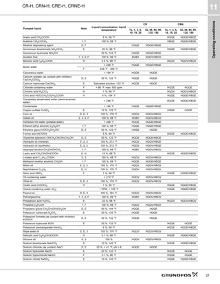
Ambient temperature and altitude
If the ambient temperature exceeds the maximum
temperature limits of the motor or the pump is installed
at an altitude exceeding the altitude values in the chart
below (3280 ft (1000 m)), the motor must not be fully
loaded due to the risk of overheating.
Overheating may result from excessive ambient
temperatures or the low density and consequently low
cooling effect of the air at high altitudes. In such cases,
it may be necessary to use a motor with a higher rated
output (P2).
See also Installation altitude on page 10.
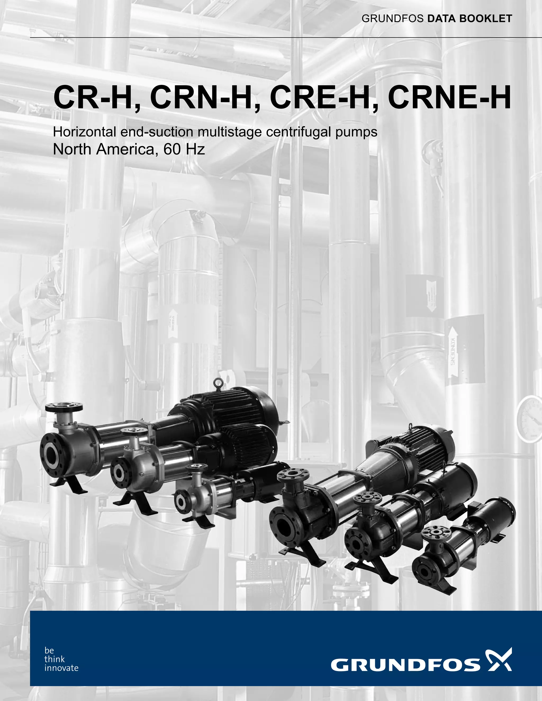
Fig. 7 Relationship between motor output (P2) and
ambient temperature/altitude
Legend
Example: From fig. 7 it appears that P2 must be
reduced to 88 % when a pump with a NEMA Premium
efficiency, ML motor is installed 15,584 feet above sea
level. At an ambient temperature of 167 °F, P2 of an
energy efficient motor must be reduced to 74 % of
rated output.
TM02
1805
2001
Position 12 Position 3
Standard Baldor
Standard ML, MLE
TM03
4272
2006
Pos. Description
1 NEMA energy efficient motors (EPAct)
2 NEMA Premium efficiency motors
MLE motor
power
[HP (kW)]
Motor
make
Voltage
[V]
Max.
ambient
temp.
[°F (°C)]
Max.
altitude
above sea
level
[ft (m)]
1/2 to 2
(0.37 to 1.5)
MLE 1 x 200-240 122 (50)
3280 (1000)
1 to 15
(0.74 to 11.18)
MLE 3 x 440-480 122 (50)
1 1/2 to 7 1/2
(1.1 to 5.5)
MLE 3 x 200-240 104 (40)
20 to 30
(14.91 to 22)
MLE 3 x 460-480 104 (40)
60 80 100 120 140 160 180
T [°F]
50
60
70
80
90
100
[%]
P2
1
2
3280 7382 11483 15584 ft](https://image.slidesharecdn.com/grundfoscr-hcatalog-220705044556-786af359/85/GRUNDFOS-CR-H-Catalog-pdf-9-320.jpg)
![Product
introduction
CR-H, CRN-H, CRE-H, CRNE-H
1
10
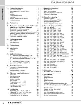
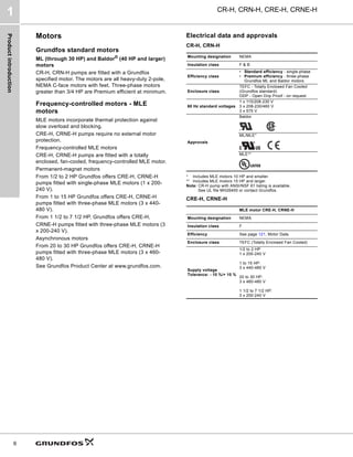
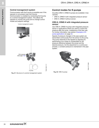
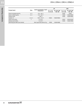
Installation altitude
Installation altitude is the height above sea level of the
installation site. Motors installed up to 3280 ft (1000 m)
above sea level can be loaded 100 %.
Motors installed more than 3280 ft (1000 m) above sea
level must not be fully loaded due to the low density
and consequently low cooling effect of the air.
MLE permanent-magnet motors
1/2 to 2 HP (1 x 200-240 V)
1 to 15 HP (3 x 440-480 V)
1 1/2 to 7 1/2 HP (3 x 200-240 V)
Fig. 8 Derating of motor output (P2) in relation to altitude
above sea level
MLE asynchronous motors
20 to 30 HP (3 x 460-480 V)
Fig. 9 Derating of motor output (P2) in relation to altitude
above sea level
TM05
9217
3513
TM05
9218
3513
1
0.99
0.98
0.97
0.96
0.95
0.94
0.93
0.92
0.91
0.90
0.89
0.88
0
0
1000 1200 1400 1600 1800 2000 2200
0 3280 3940 4590 5250 5900 6560 7220
[m]
[ft]
P2
[%]
Altitude
0.5
0.6
0.7
0.8
0.9
1
[%]
P2
3280 7380 11480
1000
[ft]
[m]
2250 3500](https://image.slidesharecdn.com/grundfoscr-hcatalog-220705044556-786af359/85/GRUNDFOS-CR-H-Catalog-pdf-10-320.jpg)
![Performance
range
CR-H, CRN-H, CRE-H, CRNE-H
4
14
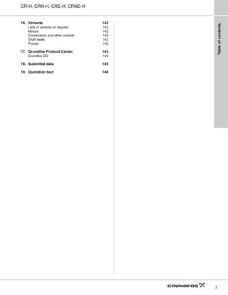
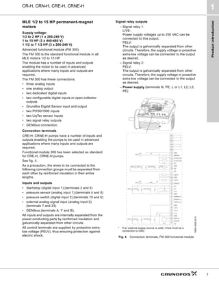
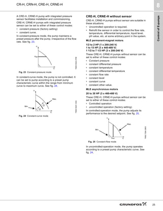
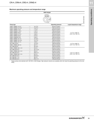
4. Performance range
CR-H, CRN-H
CRE-H, CRNE-H
TM04
4552
1212
1 2 3 4 6 8 10
10 15 20 30 40 60 80 100
100 150 200 300 400 600 800
Q [US GPM]
20
30
40
60
80
100
200
300
400
600
800
1000
[ft]
H
10
10
20
30
40
50
60
80
100
100
200
300
[m]
H
1
1 2 3 4 5 6 8 10
10 20 30 40 50 60 80 Q [m³/h]
60 Hz
CR
90
H
CR
64
H
CR
45
H
CR
32
H
CR
20
H
CR
15
H
CR
10
H
CR
5
H
CR
3
H
CR
1
H
CR
1s
H
1 2 3 4 6 8 10
10 15 20 30 40 60 80 100
100 150 200 300 400 600 800
Q [US GPM]
0
20
40
60
80
[%]
Eff
TM04
9018
1112
3 4 6 8 10 15 20 30 40 60 80 100 150 200 300 400 600 800
Q [US GPM]
20
30
40
60
80
100
200
300
400
600
800
1000
[ft]
H
10
10
20
30
40
50
60
80
100
100
200
300
[m]
H
1
1 2 3 4 5 6 7 8 910
10 20 30 40 50 60 7080 100
100Q [m³/h]
60 Hz
CRE
90
H
CRE
64
H
CRE
45
H
CRE
32
H
CRE
20
H
CRE
15
H
CRE
10
H
CRE
5
H
CRE
3
H
CRE
1
H
3 4 6 8 10 15 20 30 40 60 80 100 150 200 300 400 600 800
Q [US GPM]
0
20
40
60
80
[%]
Eff](https://image.slidesharecdn.com/grundfoscr-hcatalog-220705044556-786af359/85/GRUNDFOS-CR-H-Catalog-pdf-14-320.jpg)
![Product
range
CR-H, CRN-H, CRE-H, CRNE-H
5
15
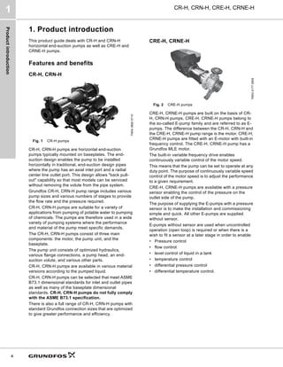
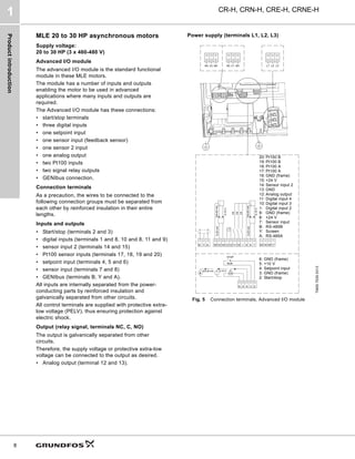
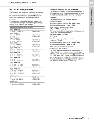
5. Product range
● Available
* There are a variety of flange size options available for this size CR-H (see list above). Selection should be based on replacement size or choose
listed size for new installations.
Range
CR, CRE
1s H
CR, CRE
1 H
CR, CRE
3 H
CR, CRE
5 H
CR,CRE
10 H
CR,CRE
15 H
CR,CRE
20 H
CR, CRE
32 H
CR, CRE
45 H
CR, CRE
64 H
CR 90 H
Nominal flow rate [US GPM] 4.5 8.5 15 30 55 95 110 140 220 340 440
Temperature range [°F] -4 to +250 -22 to +250
Temperature range [°F] - on
request
-40 to +356 -40 to +356
Maximum working pressure
[psi]
360 360 360 360 360 360 360 435 435 435 435
Maximum pump efficiency [%] 35 49 59 64 70 72 72 73 80 82 85
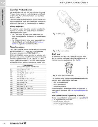
CR-H pumps
CR: Flow range [US GPM] 0.5 - 5.7 1 - 12.8 1.5 - 23.8 3-45 5.5 - 70 9.5 - 125 11-155 14-210 22-310 34-450 44-630
CR: Maximum shut-off pressure
(H [ft])
745 785 785 780 810 760 675 935 930 590 570
CR: Motor power [HP] 1/3 - 2 1/2 - 3 1/2 - 5 3/4 - 7 1/2 3/4 - 15 2 - 25 3 - 25 3 - 50 7 1/2 - 60 7 1/2 - 60 15-60
CRE-H pumps
CRE: Flow range [US GPM] 0 - 5.7 0 - 12.8 0 - 23.8 0-45 0-70 0-125 0-155 0-210 0-310 0-450 0-630
CRE: Maximum shut-off
pressure (H [ft])
745 785 785 780 810 760 675 670 470 310 270
CRE: Motor power [HP] 1/3 - 2 1/3 - 3 1/3 - 5 3/4 - 7.5 3/4 - 15 2 - 25 3 - 25 3 - 30 7 1/2 - 30 7 1/2 - 30 15-30
Version
CR-H, CRE-H versions: Cast
iron and stainless steel AISI
304
● ● ● ● ● ● ● ● ● ● ●
CRN-H, CRNE-H versions:
Stainless steel AISI 316
● ● ● ● ● ● ● ● ● ● ●
CR-H, CRE-H pipe connection
ANSI connection type GA GA GA GA G22* G22* G22* G22* G33* G44* G44*
ANSI flange class [lb] 125/250 125/250 125/250 125/250 125/250 125/250 125/250 125/250 125/250 125/250 125/250
CRN-H, CRNE-H pipe connection
ANSI connection type GA GA GA GA G22* G22* G22* G22* G33* G44* G44*
ANSI flange class [lb] 150/300 150/300 150/300 150/300 150/300 150/300 150/300 150/300 150/300 150/300 150/300
Pipe connection - inlet x outlet x impeller size reference
GA ANSI 1.5" x 1" x 6",
1.5" x 1" x 8"
● ● ● ● ● ● ● ●
G05 ANSI 2" x 1" x 10" ● ● ● ●
GB ANSI 3" x 1.5" x 6",
3" x 1.5" x 8"
● ● ● ●
GC ANSI 3" x 2" x 6" ● ● ●
G10 ANSI 3" x 2" x 6" ● ● ●
G50 ANSI 3" x 1.5" x 8",
3" x 1.5" x 10"
● ● ●
G60 ANSI 3" x 2" x 8",
3" x 2" x 10"
● ● ● ●
G20 ANSI 3" x 1.5" x 13" ● ● ●
G30 ANSI 3" x 2" x 13" ● ● ●
G70 ANSI 4" x 3" x 8",
4" x 3" x 10"
● ●
G40 ANSI 4" x 3" x 10",
4" x 3" x 13"
● ●
G22 ANSI 2" x 2" ● ● ● ●
G33 ANSI 3" x 3" ● ●
G44 ANSI 4" x 4" ● ●](https://image.slidesharecdn.com/grundfoscr-hcatalog-220705044556-786af359/85/GRUNDFOS-CR-H-Catalog-pdf-15-320.jpg)
![Identification
CR-H, CRN-H, CRE-H, CRNE-H
6
16
6. Identification
Type key
CR-H, CRE-H
Codes
1)
If a pump incorporates more than two pump versions, the code for
the pump version is X. X also indicates special pump versions not
listed above.
2)
The pipe connection code designates the pump as a CR
horizontal end-suction pump.
Example CR E 5 s -4 -2 H -GA -G -E -HQQE
Type range
Pump with integrated frequency
control
Rated flow rate [m3
/h]
All impellers with reduced diameter
(applies only to CR, CRN 1s H)
Number of impellers
Number of reduced diameter impellers (applies
only to CR, CR(E), CRN, CRN(E) 32, 45, 64,
90 H)
Code for pump version
Code for pipe connection
Code for materials
Code for rubber parts
Code for shaft seal
Example H -GA -A -E -H QQ E
Pump version
HB Oversize motor
HE Certificate/approval
HF
CR pump for high temperatures (air
cooled top assembly)
H Basic horizontal version
HI Different pressure rating
HJ Pump with different max speed
HK Pump with low NPSH
HM Magnetic drive
HN Fitted with sensor
HP Undersize motor
HR Belt-driven pump
HT
Oversize motor (two flange sizes bigger)
(two flange sizes bigger)
X Special version1)
Example H -GA -A -E -H QQ E
Pipe connection (inlet x outlet x impeller size
reference)2)
GA ANSI 1.5" x 1" x 6", 1.5" x 1" x 8"
G05 ANSI 2" x 1" x 10"
GB ANSI 3" x 1.5" x 6", 3" x 1.5" x 8"
GC ANSI 3" x 2" x 6"
G10 ANSI 3" x 2" x 6"
G50 ANSI 3" x 1.5" x 8", 3" x 1.5" x 10"
G60 ANSI 3" x 2" x 8", 3" x 2" x 10"
G20 ANSI 3" x 1.5" x 13"
G30 ANSI 3" x 2" x 13"
G70 ANSI 4" x 3" x 8", 4" x 3" x 10"
G40 ANSI 4" x 3" x 10", 4" x 3" x 13"
G22 ANSI 2" x 2"
G33 ANSI 3" x 3"
G44 ANSI 4" x 4"
Materials
A Basic version
D Carbon-graphite filled PTFE (bearings)
G Wetted parts AISI 316
GI All parts stainless steel, wetted parts AISI 316
K Bronze (bearings)
S SiC bearings + PTFE neck rings
X Special version
Code for rubber parts
E EPDM
F FXM
K FFKM
V FKM
Shaft seal
H Balanced cartridge seal with O-ring
K Metal bellows cartridge seal
O Double seal, back-to-back
P Double seal, tandem
X Special version
B Carbon, synthetic resin-impregnated
H Cemented tungsten carbide, embedded (hybrid)
Q Silicon carbide
U Cemented tungsten carbide
X Other ceramics
E EPDM
F FXM
K FFKM
V FKM](https://image.slidesharecdn.com/grundfoscr-hcatalog-220705044556-786af359/85/GRUNDFOS-CR-H-Catalog-pdf-16-320.jpg)
![MLE
technical
data
CR-H, CRN-H, CRE-H, CRNE-H
7
17
7. MLE technical data
Grundfos MLE motors are equipped with NEMA
standard C-face flanges.
Grundfos MLE motors are recognized under the
Component Recognition Program of Underwriters
Laboratories Inc. for the United States and Canada.
MLE motors are equipped with a reinforced bearing
system with locked bearings at the drive end, either a
deep-groove ball bearing or an angular-contact
bearing depending on the motor model.
This ensures an even uptake of the load in order to
maximize the lifetime of the bearings, which are
guaranteed for a minimum of 18,000 hours service life.
At the non-drive end, the motors are fitted with
bearings with axial clearance in order to meet
production tolerances while allowing for thermal
expansion during motor operation. This ensures
trouble-free operation and long life.
MLE permanent-magnet motors 1/2 - 2 HP
(2-pole) 1/60/200-240
2-pole dimensional data
TM05
6786
5012
Power
[HP]
NEMA frame
Stator housing [inches (mm)]
Shaft end
[inches (mm)]
AC AD AF L LB LL D E
1/2
56C
4.80
(122)
6.22
(158)
4.17
(106)
10.55
(268)
8.46
(215)
7.56
(192)
0.63
(15.9)
2.06 (52.3)
3/4
1
1 1/2
2
4.80
(122)
6.22
(158)
4.17
(106)
11.34
(288)
9.25
(235)
7.56
(192)
0.63
(15.9)
2.06
(52.3)
Power
[HP]
NEMA Frame
Flange [inches (mm)] Cable entries [mm]
LA M N P S T O
1/2
56C
0.63
(16)
5.87
(149.2)
4.50
(114.3)
6.50
(165)
3/8"
0.16
(4)
1/2" NPT (4)
3/4
1
1 1/2
2
1.42
(36)
5.87
(149.2)
4.50
(114.3)
6.50
(165)
3/8"
0.16
(4)
1/2" NPT (4)](https://image.slidesharecdn.com/grundfoscr-hcatalog-220705044556-786af359/85/GRUNDFOS-CR-H-Catalog-pdf-17-320.jpg)
![MLE
technical
data
CR-H, CRN-H, CRE-H, CRNE-H
7
18
MLE permanent-magnet motors 1-15 HP
(2-pole) 3/60/440-480
Dimensional data
TM06
6518
3316
Power
[HP]
NEMA frame
Stator housing [inches (mm)]
Shaft end
[inches (mm)]
P AB AE AF C AG LL U AH
1
56C
4.80
(122)
6.22
(158)
5.28
(134)
5.28
(134)
12.13
(308)
10.04
(255)
9.13
(232)
0.63
(15.9)
2.06
(52.3)
1 1/2
4.80
(122)
6.22
(158)
5.28
(134)
5.28
(134)
12.91
(328)
10.83
(275)
9.13
(232)
0.63
(15.9)
2.06
(52.3)
20
4.80
(122)
6.22
(158)
5.28
(134)
5.28
(134)
12.39
(314.75)
10.51
(267)
9.13
(232)
0.63
(16.075)
1.88
(47.75)
30
182TC
4.80
(122)
6.22
(158)
5.28
(134)
5.28
(134)
13.46
(342)
10.83
(275)
9.13
(232)
1.13
(28.6)
2.62
(66.6)
5
7.53
(191.3)
7.91
(201)
5.73
(145.5)
5.73
(145.5)
15.89
(403.6)
13.15
(334)
11.02
(280)
1.13
(28.6)
2.74
(69.6)
7 1/2
213TC
7.53
(191.3)
7.91
(201)
5.73
(145.5)
5.73
(145.5)
17.75
(450.9)
14.37
(365)
11.02
(280)
1.37
(34.9)
3.38
(85.9)
10
10.04
(254.9)
9.33
(237)
6.81
(173)
6.81
(173)
18.70
(474.9)
15.31
(389)
12.48
(317)
1.37
(34.9)
3.38
(85.9)
15 254TC
10.04
(254.9)
9.33
(237)
6.81
(173)
6.81
(173)
19.74
(501.3)
15.98
(406)
12.48
(317)
1.63
(41.3)
3.75
(95.3)
Power
[HP]
NEMA frame
Flange [inches (mm)] Cable entries [mm]
LA AJ AK BD BF BB O
10
56C
0.63
(16)
5.87
(149.2)
4.50
(114.3)
6.50
(165)
3/8"
0.16
(4)
1/2" NPT (4)
1 1/2
20
1.42
(36)
5.87
(149.2)
4.50
(114.3)
6.50
(165)
3/8"
0.16
(4)
1/2" NPT (4)
30
182TC
5
0.51
(12.9)
5.87
(149.2)
4.50
(114.3)
6.53
(165.8)
3/8"
0.16
(4)
1/2" NPT (5)
7 1/2
213TC
0.75
(19)
7.25
(184.15)
8.50
(215.9)
8.50
(215.9)
1/2" - 13
0.25
(6.35)
1/2" NPT (5)
10
0.79
(20)
7.25
(184.15)
8.50
(215.9)
8.68
(220.5)
1/2" - 13
0.25
(6.35)
3/4" NPT (1) & 1/2" NPT (5)
15 254TC
0.79
(20)
7.25
(184.15)
8.50
(215.9)
8.68
(220.5)
1/2" - 13
0.25
(6.35)
3/4" NPT (1) & 1/2" NPT (5)](https://image.slidesharecdn.com/grundfoscr-hcatalog-220705044556-786af359/85/GRUNDFOS-CR-H-Catalog-pdf-18-320.jpg)
![MLE
technical
data
CR-H, CRN-H, CRE-H, CRNE-H
7
19
MLE permanent-magnet motors 1 1/2 - 7 1/2 HP
1 1/2 - 7 1/2 HP (2-pole) 3/60/200-240
Dimensional data
TM06
6518
3316
Power
[HP]
NEMA frame
Stator housing [inches (mm)]
Shaft end
[inches (mm)]
P AB AE AF C AG LL U AH
1 1/2
56C
4.80
(122)
6.22
(158)
5.28
(134)
5.28
(134)
12.13
(308)
10.04
(255)
9.13
(232)
0.63
(15.9)
2.06
(52.3)
2
4.80
(122)
6.22
(158)
5.28
(134)
5.28
(134)
12.91
(328)
10.83
(275)
9.13
(232)
0.63
(15.9)
2.06
(52.3)
3
182TC
7.53
(191.3)
7.917
(201)
5.73
(145.5)
5.73
(145.5)
15.89
(403.6)
13.15
(334)
11.02
(280)
1.13
(28.6)
2.74
(69.6)
5
7.53
(191.3)
7.91
(201)
5.73
(145.5)
5.73
(145.5)
15.89
(403.6)
13.15
(334)
11.02
(280)
1.13
(28.6)
2.74
(69.6)
7 1/2 213TC
10.04
(254.9)
9.33
(237)
6.81
(173)
6.81
(173)
18.70
(474.9)
15.31
(389)
12.48
(317)
1.37
(34.9)
3.38
(85.9)
Power
[HP]
NEMA frame
Flange [inches (mm)] Cable entries
LA AJ AK BD BF BB O
1 1/2
56C
0.63
(16)
5.87
(149.2)
4.50
(114.3)
6.50
(165)
3/8"
0.16
(4)
1/2" NPT (4)
2
1.42
(36)
5.87
(149.2)
4.50
(114.3)
6.50
(165)
3/8"
0.16
(4)
1/2" NPT (4)
3
182TC
0.75
(19)
7.25
(184.15)
8.50
(215.9)
8.50
(215.9)
1/2"-13
0.25
(6.35)
1/2" NPT (5)
5
0.75
(19)
7.25
(184.15)
8.50
(215.9)
8.50
(215.9)
1/2"-13
0.25
(6.35)
1/2" NPT (5)
7 1/2 213TC
0.79
(20)
7.25
(184.15)
8.50
(215.9)
8.68
(220.5)
1/2"-13
0.25
(6.35)
3/4" NPT (1) & 1/2" NPT (5)](https://image.slidesharecdn.com/grundfoscr-hcatalog-220705044556-786af359/85/GRUNDFOS-CR-H-Catalog-pdf-19-320.jpg)
![MLE
technical
data
CR-H, CRN-H, CRE-H, CRNE-H
7
20
MLE asynchronous motors 20-30 HP
(2-pole) 3/60/460-480
Dimensional data
TM04
5498
3309
Power
[HP]
Nema frame
Stator housing [inches (mm)] Shaft end [inches]
P AB AF AF C AG LL U AH
20 256TC
13.39
(340)
12.13
(308)
8.27
(210)
8.27
(210)
22.56
(573)
18.78
(477)
15.75
(400)
1.62
(41)
3.75
(95)
25 284TC
13.39
(340)
12.13
(308)
8.27
(210)
8.27
(210)
24.53
(623)
22.72
(577)
15.75
(400)
1.62
(41)
3.75
(95)
30 286TC
13.39
(340)
12.13
(308)
8.27
(210)
8.27
(210)
24.53
(623)
22.72
(577)
15.75
(400)
1.62
(41)
3.75
(95)
Power
[HP]
Nema frame
Flange [inches (mm)] Cable entries [mm]
AJ AK BD BF BB O
20 256TC
7.25
(184)
8.50
(216)
9.88
(251)
1/2"
0.26
(7)
1 x M40 + 1 x M20 + 2 x M16 + 2 x knock out M16
25 284TC
9.00
(229)
10.50
(267)
10.75
(273)
1/2"
0.32
(8)
1 x M40 + 1 x M20 + 2 x M16 + 2 x knock out M16
30 286TC
9.00
(229)
10.50
(267)
10.75
(273)
1/2"
0.32
(8)
1 x M40 + 1 x M20 + 2 x M16 + 2 x knock out M16](https://image.slidesharecdn.com/grundfoscr-hcatalog-220705044556-786af359/85/GRUNDFOS-CR-H-Catalog-pdf-20-320.jpg)
![MLE
technical
data
CR-H, CRN-H, CRE-H, CRNE-H
7
21
MLE motors for CRE-H and CRNE-H
(C-Face mounting with foot)
Dimensional sketch
Dimensional data
GR9035
TM05
3012
0812
BB
MOUNTING
SURFACE
BC
BA
BB
AJ
AK
BC
MOUNTING
SURFACE
BA
H
2F
45°
AK
AJ
DIMENSIONS FOR
FRAMES WHERE AJ IS
GREATER THAN AK
D
A
2E
E
MOUNTING
SURFACE
DIMENSIONS FOR
FRAMES WHERE AJ IS
GREATER THAN AK
MOUNTING
SURFACE
Power
[HP]
PH
NEMA frame
size
Foot dimensions [inches]
A D E 2E 2F BA + BC H
One-phase 2-pole MLE motor with foot
1/2 1 56C 6.00 3.50 2.44 4.88 3.00 2.56 0.34
3/4 1 56C 6.00 3.50 2.44 4.88 3.00 2.56 0.34
1 1 56C 6.00 3.50 2.44 4.88 3.00 2.56 0.34
1 1/2 1 56C 6.00 3.50 2.44 4.88 3.00 2.56 0.34
2 1 56C 6.00 3.50 2.44 4.88 3.00 2.56 0.34
Three-phase 2-pole MLE motor with foot
1 3 56C 6.00 3.50 2.44 4.88 3.00 2.56 0.34
1 1/2 3 56C 6.00 3.50 2.44 4.88 3.00 2.56 0.34
2 3 56C 6.00 3.50 2.44 4.88 3.00 2.56 0.34
3 3 182TC 8.90 4.50 3.75 7.50 4.50 2.87 0.41
5 3 184TC 8.90 4.50 3.75 7.50 5.50 2.87 0.41
7 1/2 3 215TC 9.96 5.25 4.25 8.50 7.00 3.75 0.41
10 3 215TC 9.60 5.25 4.25 8.50 7.00 3.75 0.41
15 3 254TC 11.30 6.25 5.00 10.00 8.25 4.50 0.53
20 3 256TC 11.30 6.25 5.00 10.00 10.00 4.50 0.53
25 3 284TSC 12.30 7.00 5.50 11.00 9.50 5.00 0.53
30 3 286TSC 12.30 7.00 5.50 11.00 11.00 5.00 0.53](https://image.slidesharecdn.com/grundfoscr-hcatalog-220705044556-786af359/85/GRUNDFOS-CR-H-Catalog-pdf-21-320.jpg)
![Advanced
use
of
MLE
motors
CR-H, CRN-H, CRE-H, CRNE-H
9
27
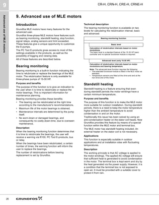
Outdoor installation
According to UL 778-C22.2 No 108-14 pumps that are
intended for outdoor use shall be marked enclosure
type 3 and the product shall be tested with rated
surface temperature down to -31 °F (-35 °C). The MLE
enclosure is approved for type 3 or 4 and rated surface
temperature down to 32 °F (0 °C), thus only for indoor
use in UL 778-C22.2 No 108-14 pump applications.
See the Installation and Operating Instructions for
additional details.
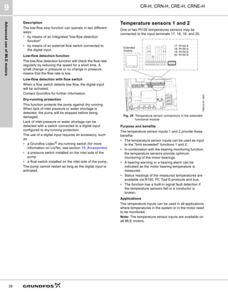
Stop function
The stop function ensures that the pump is stopped at
low or no flow. The function is also called low-flow stop
function.
Purpose and benefits
The purpose of the stop function is to stop the pump
when low flow is detected.
The stop function provides these benefits:
• The energy consumption is optimized and the
system efficiency is improved.
• Unnecessary heating of the pumped liquid which
damages pumps.
• Wear of the shaft seals is reduced.
• Noise from operation is reduced.
Applications
The stop function is used in systems with periodically
low or no consumption thus preventing the pump from
running against closed valve.
Operating conditions for the stop function
A pressure sensor, a check valve, and a diaphragm
tank are required for the stop function to operate
properly.
Note: The check valve must always be installed before
the pressure sensor. See fig. 26 and fig. 27.
Fig. 26 Position of the check valve and pressure sensor in
system with suction lift operation
Fig. 27 Position of the check valve and pressure sensor in
system with positive inlet pressure
When low flow is detected, the pump is in on/off
operation. If there is flow, the pump will continue
operating according to the setpoint. See fig. 28.
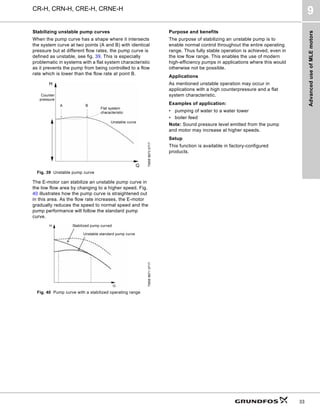
Fig. 28 Constant pressure with stop function.
Difference between start and stop pressures (∆H)
Diaphragm tank
The stop function requires a diaphragm tank of a
certain minimum size. The tank must be installed near
the outlet of the pump, and the precharge air pressure
must be 0.7 x setpoint.
Recommended diaphragm tank size:
If a diaphragm tank of the above size is installed in the
system, no additional adjustment should be necessary.
If the tank installed is too small, the pump will start and
stop often. Tank size will influence at which flow rate
the system will go into start/stop operation.
TM03
8582
1907
Pressure sensor
Diaphragm tank
Check valve
Pump
TM03
8583
1907
TM03
8477
1607
Rated flow rate of
pump [gpm (m3
h)]
CRE-H pump
Typical diaphragm tank
size [gal (liter)]
0-26 (0 - 5.9) 1s, 1, 3 2 (7.6)
27-105 (6.1 - 23.8) 5, 10, 15 4.4 (16.7)
106-176 (24.2 - 40) 20, 32 14 (53.0)
177-308 (40.2 - 70.0) 45 34 (128.7)
309-440 (70.2 - 99.9) 64, 90 62 (234.7)
441-750 (100-170) 120, 150 86 (325.5)
Diaphragm tank
Pressure sensor
Pump Check valve
Continuous operation
On/off operation
Stop pressure
Start pressure
∆H](https://image.slidesharecdn.com/grundfoscr-hcatalog-220705044556-786af359/85/GRUNDFOS-CR-H-Catalog-pdf-27-320.jpg)
![Advanced
use
of
MLE
motors
CR-H, CRN-H, CRE-H, CRNE-H
9
29
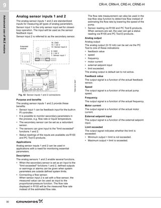
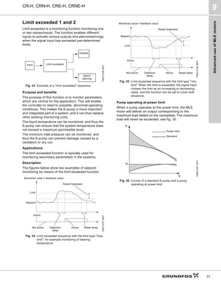
Description
The temperature sensor inputs enable several
functions.
• The temperature sensor inputs 1 and 2 can be used
as input to the "limit exceeded" functions 1 and 2. If
a limit is exceeded, this will be indicated.
The indication will be in the form of outputs (relay)
or alarms/warnings set/defined in the "limit
exceeded" functions 1 and 2.
• The temperature sensor inputs 1 and 2 can be set to
measure bearing temperature. The measured
values of temperature sensor 1 and 2 are used in
the calculation of relubrication intervals.
Additionally, the measured value can activate the
indication of a bearing warning or a bearing alarm.
In case of high bearing temperature, a warning or
an alarm can be logged and force the pump to stop.
Signal relays
Signal relays are used to give an output indication of
the current operational status of the MLE. The signal
relay is a potential free contact (also called a dry
contact). The output signals are typically transmitted to
external control systems.
Purpose and benefits
The signal relays offer these features:
• The signal relays can be remotely (via bus) or
internally controlled.
• The signal relays can be set to indicate several
types of operational status.
• A relay delay can be defined to avoid activating the
relay in case of periodic failures.
Applications
Signal relays can be used in all applications involving a
need to read out the operational status to e.g. a control
room or to a superior control system.
Description
The signal relays can be set with these three
parameters:
• relay control
• relay setup
• relay delay.
Relay control
The relay time is 0 seconds and the signal relay is
internally controlled.
The advanced relay control can only be set via the PC
Tool E-products.
Relay control has these two setting options:
• Internally controlled
The relay is internally controlled by the variable
frequency drive software according to the setup of
the relay [Ready, Fault, Operation].
• Remotely controlled
The relay is controlled via commands from the
GENIbus.
Fig. 30 Signal relay parameters for 1/2 - 10 HP pumps
Fig. 31 Signal relay parameters for 15 - 30 HP pumps](https://image.slidesharecdn.com/grundfoscr-hcatalog-220705044556-786af359/85/GRUNDFOS-CR-H-Catalog-pdf-29-320.jpg)
![Operating
conditions
CR-H, CRN-H, CRE-H, CRNE-H
11
40
Operating range of the shaft seal
The operating range of the shaft seal depends on
operating pressure, pump type, type of shaft seal and
liquid temperature. The following curves apply to clean
water and water with anti-freeze liquids. For selecting
the right shaft seal, see List of pumped liquids on page
36.
CR(E), CRN(E) 1s H through CR(E), CRN(E) 20 H
Fig. 49 Operating range of standard shaft seals for CR(E),
CRN(E) 1s H to CR(E), CRN(E) 20 H
CR(E), CRN(E) 32 H through CR, CRN 90 H
Fig. 50 Operating range of standard shaft seals for CR(E),
CRN(E) 32 H to CR, CRN 90 H
TC = tungsten carbide.
The pumping of liquids above 248 °F (120 °C) may
result in periodical noise and reduced pump life.
Standard CR-H, CRN-H pumps are not suitable for the
pumping of liquids above 248 °F (120 °C) for long
periods.
See the Grundfos "Custom-built Pumps" Product
Guide for information about pumps for extreme
temperatures and special conditions.
TM05
9659
4213
TM06
0999
1314
-40
-80 0 40 80 120 160 200 240 t [°F]
0
100
200
300
400
[psi]
p
-40 -20
-60 0 20 40 60 80 100 t [°C]
0
5
10
15
20
25
[bar]
p
HQQE
HQQV
HQQE
HQQE
-40 0 40 80 120 160 200 240 t [°F]
0
100
200
300
400
500
[psi]
p
-40 -20 0 20 40 60 80 100 t [°C]
0
5
10
15
20
25
30
[bar]
p
HQQE
HUBE / HUBV HUBE
HQQE
HQQE / HQQV
Shaft
seal
Description
Max. temp. range
[°F]
HQQE
O-ring (cartridge) (balanced seal),
SiC/SiC, EPDM
-40 to +248 °F
HBQE
O-ring (cartridge) (balanced seal),
Carbon/SiC, EPDM
+32 to +248 °F
HBQV
O-ring (cartridge) (balanced seal),
Carbon/SiC, FKM
+32 to +194 °F
HQQV
O-ring (cartridge) (balanced seal),
SiC/SiC, FKM
-4 to +194 °F
HUBE
O-ring (cartridge) (balanced seal),
TC/carbon, EPDM
+32 to +248 °F
HUBV
O-ring (cartridge) (balanced seal),
TC/carbon, FKM
+32 to +194 °F](https://image.slidesharecdn.com/grundfoscr-hcatalog-220705044556-786af359/85/GRUNDFOS-CR-H-Catalog-pdf-40-320.jpg)
![Selection
and
sizing
CR-H, CRN-H, CRE-H, CRNE-H
12
42
12. Selection and sizing
Selection of pumps
Selection of pumps should be based on:
• duty point of the pump
• sizing data such as pressure loss as a result of
height differences, friction loss in the pipes, pump
efficiency etc.
• pump materials
• pipe dimensions
• shaft seal
• inlet pressure and operating pressure.
Duty point of the pump
From a duty point it is possible to select a pump on the
basis of the curve charts in the section 13. Curve
charts/technical data starting on page 48.
Fig. 51 Example of a curve chart
Sizing data
When sizing a pump the following must be taken into
account.
• Required flow rate and pressure at the point of use.
• Pressure loss as a result of height differences
(Hgeo).
• Friction loss in the pipes (Hf).
It may be necessary to account for pressure loss in
connection with long pipes, bends or valves, etc.
• Best efficiency at the estimated duty point.
• NPSH value.
For calculation of the NPSH value, see Minimum
inlet pressure, NPSHA on page 45.
Fig. 52 Sizing data
Efficiency
Before determining the point of best efficiency, the
operating pattern of the pump must be identified. If the
pump is expected to operate in the same duty point,
then select a CR(E)-H, CRN(E)-H pump which is
operating in a duty point corresponding to the best
efficiency of the pump.
Fig. 53 Example of duty point
TM04
4551
1609
0 20 40 60 80 100 120 140 160 180 200 Q [US GPM]
0
50
100
150
200
250
300
350
400
450
500
550
600
650
700
750
800
850
900
950
[ft]
H
0 5 10 15 20 25 30 35 40 45 Q [m³/h]
0
20
40
60
80
100
120
140
160
180
200
220
240
260
280
[m]
H
0
50
100
150
200
250
300
350
400
450
500
550
600
650
700
750
800
850
900
950
[ft]
H
CR(E) 32 H
2-pole, 60 Hz
-1 (E)
-1-1 (E)
-10
-10-2
-11-2
-2 (E)
-2-1
-2-2
-3
-3-2 (E)
-4
-4-2
-5
-5-2
-6
-6-2
-7
-7-2
-8
-8-2
-9
-9-2
0 20 40 60 80 100 120 140 160 180 200 Q [US GPM]
0
1
2
3
4
P2
[hp]
0
20
40
60
80
Eff
[%]
0
1
2
P2
[kW]
P2 2/3
P2 1/1
Eff
0 20 40 60 80 100 120 140 160 180 200 Q [US GPM]
0
10
20
30
NPSH
[ft]
0
4
8
[m]
H
0
10
20
30
[ft]
H
NPSHR
TM04
3689
4804
TM02
0039
1303
Hf
NPSHR
Hv
Hgeo Pb
0 20 40 60 80 100 120 140 160 180 200 Q [US GPM]
0
50
100
150
200
250
300
350
400
450
500
550
600
650
700
750
800
850
900
950
[ft]
H
0 5 10 15 20 25 30 35 40 45 Q [m³/h]
0
20
40
60
80
100
120
140
160
180
200
220
240
260
280
[m]
H
0
50
100
150
200
250
300
350
400
450
500
550
600
650
700
750
800
850
900
950
[ft]
H
CR(E) 32 H
2-pole, 60 Hz
-1 (E)
-1-1 (E)
-10
-10-2
-11-2
-2 (E)
-2-1
-2-2
-3
-3-2 (E)
-4
-4-2
-5
-5-2
-6
-6-2
-7
-7-2
-8
-8-2
-9
-9-2
0 20 40 60 80 100 120 140 160 180 200 Q [US GPM]
0
1
2
3
4
P2
[hp]
0
20
40
60
80
Eff
[%]
0
1
2
P2
[kW]
P2 2/3
P2 1/1
Eff
0 20 40 60 80 100 120 140 160 180 200 Q [US GPM]
0
10
20
30
NPSH
[ft]
0
4
8
[m]
H
0
10
20
30
[ft]
H
NPSHR
Duty
point
Best
efficiency](https://image.slidesharecdn.com/grundfoscr-hcatalog-220705044556-786af359/85/GRUNDFOS-CR-H-Catalog-pdf-42-320.jpg)
![Selection
and
sizing
CR-H, CRN-H, CRE-H, CRNE-H
12
43
As the pump is sized on the basis of the highest
possible flow rate, it is important to always have the
duty point to the right of the optimum efficiency point
(see fig. 54, range with check mark). This must be
considered in order to keep efficiency high when the
flow rate drops.
Fig. 54 Best efficiency
Normally, E-pumps are used in applications
characterized by a variable flow rate. Consequently, it
is not possible to select a pump that is constantly
operating at optimum efficiency.
In order to achieve optimum operating economy, the
pump should be selected on the basis of the following
criteria:
• The maximum required duty point should be as
close as possible to the QH curve of the pump.
• The required duty point must be positioned so that
P2 is close to the maximum point of the 100 %
curve.
Between the minimum and maximum performance
curve E-pumps have an infinite number of performance
curves each representing a specific speed. Therefore
it may not be possible to select a duty point close to
the 100 % curve.
Fig. 55 Minimum and maximum performance curves
In situations where it is not possible to select a duty
point close to the 100 % curve, the affinity equations to
the right can be used. The head (H), the flow rate (Q)
and the input power (P) are all the appropriate
variables for the motor speed (n).
Note: The approximate formulas apply on condition
that the system characteristic remains unchanged for
nn and nx, and that it is based on the formula H = k x
Q2, where k is a constant.
The power equation implies that the pump efficiency is
unchanged at the two speeds. In practice this is not
correct.
Finally, it is worth noting that the efficiencies of the
frequency converter and the motor must be taken into
account if a precise calculation of the power saving
resulting from a reduction of the pump speed is
wanted.
Fig. 56 Affinity equations
Legend
TM02
8579
0504
TM02
7572
4803
eff
US GPM
Optimum point
0 Q [US GPM]
0
H
[ft]
Max. curve
Min. curve
TM00
8720
3496
Hn Rated head in feet
Hx Current head in feet
Qn Rated flow rate in US gpm
Qx Current flow rate in US gpm
nn Rated motor speed in min-1 (nn = 3500 min-1)
nx Current motor speed in min-1
n Rated efficiency in %
x Current efficiency in %
H
Q
Eta
Q
P
Q
Hn
nn
nx
n
x
------
- 1
ª
Qn
Qx
Hx
Qx
P
n
Px
------
-
nn
nx
------
3
=
Qn
Pn
H
n
H
x
-------
n
n
n
x
------
2
=
Px
Q
n
Q
x
-------
-
nn
n
x
------
=
Eta](https://image.slidesharecdn.com/grundfoscr-hcatalog-220705044556-786af359/85/GRUNDFOS-CR-H-Catalog-pdf-43-320.jpg)
![Selection
and
sizing
CR-H, CRN-H, CRE-H, CRNE-H
12
46
How to read the curve charts
Fig. 61 How to read the curve charts
TM04
4551
1609
0 20 40 60 80 100 120 140 160 180 200 Q [US GPM]
0
50
100
150
200
250
300
350
400
450
500
550
600
650
700
750
800
850
900
950
[ft]
H
0 5 10 15 20 25 30 35 40 45 Q [m³/h]
0
20
40
60
80
100
120
140
160
180
200
220
240
260
280
[m]
H
0
50
100
150
200
250
300
350
400
450
500
550
600
650
700
750
800
850
900
950
[ft]
H
CR(E) 32 H
2-pole, 60 Hz
-1 (E)
-1-1 (E)
-10
-10-2
-11-2
-2 (E)
-2-1
-2-2
-3
-3-2 (E)
-4
-4-2
-5
-5-2
-6
-6-2
-7
-7-2
-8
-8-2
-9
-9-2
0 20 40 60 80 100 120 140 160 180 200 Q [US GPM]
0
1
2
3
4
P2
[hp]
0
20
40
60
80
Eff
[%]
0
1
2
P2
[kW]
P2 2/3
P2 1/1
Eff
0 20 40 60 80 100 120 140 160 180 200 Q [US GPM]
0
10
20
30
NPSH
[ft]
0
4
8
[m]
H
0
10
20
30
[ft]
H
NPSHR
Number of stages.
First figure: number of
stages; second figure:
number of reduced-
diameter impellers.
The efficiency curve
shows the efficiency of
the pump. The efficiency
curve is an average
curve of all the pump
types shown in the chart.
The efficiency of pumps
with reduced-diameter
impellers is approx. 2 %
lower than the efficiency
curve shown in the chart.
Pump type, number
of poles and
frequency.
QH curve for the
individual pump. The
bold curves indicate
the recommended
performance range
for best efficiency.
The power curves
indicate pump input
power per stage.
Curves are shown for
complete (1/1) and
for reduced-diameter
(2/3) impellers.
The NPSHR curve is
an average curve for
all the variants
shown. When sizing
the pumps, add a
safety margin of at
least 2.0 feet.](https://image.slidesharecdn.com/grundfoscr-hcatalog-220705044556-786af359/85/GRUNDFOS-CR-H-Catalog-pdf-46-320.jpg)
![Selection
and
sizing
CR-H, CRN-H, CRE-H, CRNE-H
12
47
Guidelines to performance curves
The guidelines below apply to the curves shown on the
following pages:
• The motors used for the measurements are
standard motors (TEFC or MLE).
• Measurements have been made with airless water
at a temperature of 68 °F (20 °C).
• The curves apply to a kinematic viscosity of = 1
mm2
/s (1 cSt).
• Due to the risk of overheating, the pumps must not
be used at a flow rate below the minimum flow rate.
• The QH curves apply to actual speed with the motor
types mentioned at 60 Hz.
The curve below shows the minimum flow rate as a
percentage of the nominal flow rate in relation to the
liquid temperature. The dotted line shows a CR(E)-H,
CRN(E)-H pump fitted with an air-cooled top assembly.
Fig. 62 Minimum flow rate
TM02
7538
3703
40 60 80 100 120 140 160 180 t [°F]
0
10
20
30
Qmin
[%]
40 60 80 100 120 140 160 180 t [°C]
140 176 212 248 284 320 356
104](https://image.slidesharecdn.com/grundfoscr-hcatalog-220705044556-786af359/85/GRUNDFOS-CR-H-Catalog-pdf-47-320.jpg)
![CR,
CRN
1s
H
GA
13
48
CR-H, CRN-H, CRE-H, CRNE-H
Curve charts/technical data
CR, CRN 1s H GA
13. Curve charts/technical data
CR, CRN 1s H GA
TM04
4545
4610
0.0 0.5 1.0 1.5 2.0 2.5 3.0 3.5 4.0 4.5 5.0 5.5 Q [US GPM]
0
50
100
150
200
250
300
350
400
450
500
550
600
650
700
750
[ft]
H
0.0 0.2 0.4 0.6 0.8 1.0 1.2 Q [m³/h]
0
20
40
60
80
100
120
140
160
180
200
220
[m]
H
0
50
100
150
200
250
300
350
400
450
500
550
600
650
700
750
[ft]
H
CR 1s H
2-pole, 60 Hz
CRN 1s H
ISO 9906 Annex A
GA
-10
-11
-12
-13
-15
-17
-19
-2
-21
-23
-25
-27
-3
-4
-5
-6
-7
-8
-9
0.0 0.5 1.0 1.5 2.0 2.5 3.0 3.5 4.0 4.5 5.0 5.5 Q [US GPM]
0.00
0.02
0.04
0.06
P2
[hp]
0
10
20
30
Eff
[%]
0.00
0.02
0.04
P2
[kW]
Eff
P2
0.0 0.5 1.0 1.5 2.0 2.5 3.0 3.5 4.0 4.5 5.0 5.5 Q [US GPM]
0
5
10
15
NPSH
[ft]
0
2
4
[m]
H
0
5
10
15
[ft]
H
NPSHR](https://image.slidesharecdn.com/grundfoscr-hcatalog-220705044556-786af359/85/GRUNDFOS-CR-H-Catalog-pdf-48-320.jpg)
![CR,
CRN
1s
H
GA
13
49
CR-H, CRN-H, CRE-H, CRNE-H Curve charts/technical data
CR, CRN 1s H GA
Dimensions and weights GA (1.5" x 1" x 6", 1.5" x 1" x 8")
Note: Terminal box is on top of ML motors (through 30 HP). Baldor motors have terminal box on the side (40 HP and larger). Reference D2 dimension.
TM04
4642
0510
Pump type HP PH
Dimensions [inches]
Ship. wt.
[lbs]
TEFC
B1 B1+B2 E1 E3 E4 D1 D2 D3 D4 D5 D6
CR(N) 1s-2 H 1/3
1 13.07 22.38 3.00 15.63 18.63 5.19 3.00 3.50 1.75 3.00 6.19 76
3 13.07 20.69 3.00 15.63 18.63 4.63 3.50 3.50 1.75 3.00 5.57 73
CR(N) 1s-3 H 1/3
1 13.07 22.38 3.00 15.63 18.63 5.19 3.00 3.50 1.75 3.00 6.19 76
3 13.07 20.69 3.00 15.63 18.63 4.63 3.50 3.50 1.75 3.00 5.57 73
CR(N) 1s-4 H 1/3
1 13.75 23.07 3.00 16.32 19.32 5.19 3.00 3.50 1.75 3.00 6.19 77
3 13.75 21.38 3.00 16.32 19.32 4.63 3.50 3.50 1.75 3.00 5.57 74
CR(N) 1s-5 H 1/3
1 14.5 23.75 3.00 17.07 20.07 5.19 3.00 3.50 1.75 3.00 6.19 78
3 14.5 22.07 3.00 17.07 20.07 4.63 3.50 3.50 1.75 3.00 5.57 75
CR(N) 1s-6 H 1/2
1 15.19 24.5 3.00 17.75 20.75 5.19 3.00 3.50 1.75 3.00 6.19 80
3 15.19 22.82 3.00 17.75 20.75 4.63 3.50 3.50 1.75 3.00 5.57 76
CR(N) 1s-7 H 1/2
1 15.88 25.19 3.00 18.44 21.44 5.19 3.00 3.50 1.75 3.00 6.19 81
3 15.88 23.50 3.00 18.44 21.44 4.63 3.50 3.50 1.75 3.00 5.57 77
CR(N) 1s-8 H 1/2
1 16.63 25.88 3.00 19.19 22.19 5.19 3.00 3.50 1.75 3.00 6.19 81
3 16.63 24.19 3.00 19.19 22.19 4.63 3.50 3.50 1.75 3.00 5.57 77
CR(N) 1s-9 H 3/4
1 17.32 27.25 3.00 19.88 22.88 5.19 3.00 3.50 1.75 3.00 6.19 89
3 17.32 24.94 3.00 19.88 22.88 4.63 3.50 3.50 1.75 3.00 5.57 79
CR(N) 1s-10 H 3/4
1 18.00 27.94 3.00 20.57 23.57 5.19 3.00 3.50 1.75 3.00 6.19 89
3 18.00 25.63 3.00 20.57 23.57 4.63 3.50 3.50 1.75 3.00 5.57 79
CR(N) 1s-11 H 3/4
1 18.75 28.63 3.00 21.32 24.32 5.19 3.00 3.50 1.75 3.00 6.19 90
3 18.75 26.32 3.00 21.32 24.32 4.63 3.50 3.50 1.75 3.00 5.57 80
CR(N) 1s-12 H 3/4
1 19.44 29.38 3.00 22.00 25.00 5.19 3.00 3.50 1.75 3.00 6.19 91
3 19.44 27.07 3.00 22.00 25.00 4.63 3.50 3.50 1.75 3.00 5.57 81
CR(N) 1s-13 H 1
1 20.13 31.38 3.00 22.69 25.69 5.75 3.00 3.50 1.75 3.00 7.19 97
3 20.13 27.75 3.00 22.69 25.69 4.63 3.50 3.50 1.75 3.00 5.57 82
CR(N) 1s-15 H 1
1 21.57 32.75 3.00 24.13 27.13 5.75 3.00 3.50 1.75 3.00 7.19 99
3 21.57 29.19 3.00 24.13 27.13 4.63 3.50 3.50 1.75 3.00 5.57 84
CR(N) 1s-17 H 1 1/2
1 23.00 34.69 3.00 25.57 28.57 5.75 3.00 3.50 1.75 3.00 7.19 113
3 23.00 31.75 3.00 25.57 28.57 4.63 3.50 3.50 1.75 3.00 5.57 86
CR(N) 1s-19 H 1 1/2
1 24.44 36.07 3.00 26.94 29.94 5.75 3.00 3.50 1.75 3.00 7.19 119
3 24.44 33.19 3.00 26.94 29.94 4.63 3.50 3.50 1.75 3.00 5.57 92
CR(N) 1s-21 H 1 1/2
1 25.82 37.50 3.00 28.38 31.38 5.75 3.00 3.50 1.75 3.00 7.19 120
3 25.82 34.63 3.00 28.38 31.38 4.63 3.50 3.50 1.75 3.00 5.57 93
CR(N) 1s-23 H 1 1/2
1 27.25 38.94 3.00 29.82 32.82 5.75 3.00 3.50 1.75 3.00 7.19 128
3 27.25 36.00 3.00 29.82 32.82 4.63 3.50 3.50 1.75 3.00 5.57 101
CR(N) 1s-25 H 2
1 28.69 41.25 3.00 31.25 34.25 5.75 3.00 3.50 1.75 3.00 7.19 133
3 28.69 40.07 3.00 31.25 34.25 4.38 3.50 3.50 1.75 3.00 7.07 124
CR(N) 1s-27 H 2
1 30.07 42.63 3.00 32.63 35.63 5.75 3.00 3.50 1.75 3.00 7.19 134
3 30.07 41.44 3.00 32.63 35.63 4.38 3.50 3.50 1.75 3.00 7.07 125
6.50"
5.25"
11.75"](https://image.slidesharecdn.com/grundfoscr-hcatalog-220705044556-786af359/85/GRUNDFOS-CR-H-Catalog-pdf-49-320.jpg)
![CR,
CRE,
CRN,
CRNE
1
H
GA
13
50
CR-H, CRN-H, CRE-H, CRNE-H
Curve charts/technical data
CR, CRE, CRN, CRNE 1 H GA
CR, CRE, CRN, CRNE 1 H GA
TM04
4546
0912
0 1 2 3 4 5 6 7 8 9 10 11 Q [US GPM]
0
50
100
150
200
250
300
350
400
450
500
550
600
650
700
750
800
[ft]
H
0.0 0.5 1.0 1.5 2.0 2.5 Q [m³/h]
0
20
40
60
80
100
120
140
160
180
200
220
240
[m]
H
0
50
100
150
200
250
300
350
400
450
500
550
600
650
700
750
800
[ft]
H
CR(E) 1 H
2-pole, 60 Hz
CRN(E) 1H
ISO 9906 Annex A
GA
-10
-11
-12
-13
-15
-17
-19
-2
-21
-23
-25
-27
-3
-4
-5
-6
-7
-8
-9
0 1 2 3 4 5 6 7 8 9 10 11 Q [US GPM]
0.00
0.04
0.08
P2
[hp]
0
20
40
Eff
[%]
0.00
0.02
0.04
0.06
P2
[kW]
Eff
P2
0 1 2 3 4 5 6 7 8 9 10 11 Q [US GPM]
0
5
10
15
NPSH
[ft]
0
2
4
[m]
H
0
5
10
15
[ft]
H
NPSHR](https://image.slidesharecdn.com/grundfoscr-hcatalog-220705044556-786af359/85/GRUNDFOS-CR-H-Catalog-pdf-50-320.jpg)
![CR,
CRE,
CRN,
CRNE
1
H
GA
13
51
CR-H, CRN-H, CRE-H, CRNE-H Curve charts/technical data
CR, CRE, CRN, CRNE 1 H GA
Dimensions GA (1.5" x 1" x 6", 1.5" x 1" x 8")
Note: Terminal box is on top of ML motors (through 30 HP). Baldor motors have terminal box on the side (40 HP and larger). Reference D2 dimension.
* Dimensions shown for three-phase MLE motors are for 460 V versions. See page 19 for 200-240 V, three-phase dimensions.
TM06
2478
1014
-
TM04
4642
0310
Pump type HP PH
Dimensions [in]
TEFC
Ship.
wt.
[lbs]
Dimensions [in]
MLE*
Ship.
wt.
[lbs]
B1 B1+B2 E1 E3 E4 D1 D2 D3 D4 D5 D6 D1 D2 AG B1+B2
CR(N) 1-2 H 1/3
1 13.07 22.38 3.00 15.63 18.63 5.19 3.00 3.50 1.75 3.00 6.19 76 - - - - -
3 13.07 20.69 3.00 15.63 18.63 4.63 3.50 3.50 1.75 3.00 5.57 73 - - - - -
CR(N) 1-3 H 1/3
1 13.07 22.38 3.00 15.63 18.63 5.19 3.00 3.50 1.75 3.00 6.19 76 - - - - -
3 13.07 20.69 3.00 15.63 18.63 4.63 3.50 3.50 1.75 3.00 5.57 73 - - - - -
CR(N)(E) 1-4 H 1/2
1 13.75 23.07 3.00 16.32 19.32 5.19 3.00 3.50 1.75 3.00 6.19 78 4.80 6.22 8.34 22.21 78
3 13.75 21.38 3.00 16.32 19.32 4.63 3.50 3.50 1.75 3.00 5.57 74 - - - - -
CR(N) 1-5 H 1/2
1 14.50 23.75 3.00 17.07 20.07 5.19 3.00 3.50 1.75 3.00 6.19 79 - - - -
3 14.50 22.07 3.00 17.07 20.07 4.63 3.50 3.50 1.75 3.00 5.57 75 - - - -
CR(N)(E) 1-6 H 3/4
1 15.19 25.13 3.00 17.75 20.75 5.19 3.00 3.50 1.75 3.00 6.19 86 4.80 6.22 8.34 23.65 80
3 15.19 22.82 3.00 17.75 20.75 4.63 3.50 3.50 1.75 3.00 5.57 76 - - - - -
CR(N) 1-7 H 3/4
1 15.88 25.82 3.00 18.44 21.44 5.19 3.00 3.50 1.75 3.00 6.19 87 - - - -
3 15.88 23.50 3.00 18.44 21.44 4.63 3.50 3.50 1.75 3.00 5.57 77 - - - -
CR(N) 1-8 H 1
1 16.63 27.82 3.00 19.19 22.19 5.75 3.00 3.50 1.75 3.00 7.19 93 - - - -
3 16.63 24.19 3.00 19.19 22.19 4.63 3.50 3.50 1.75 3.00 5.57 78 - - - -
CR(N)(E) 1-9 H 1
1 17.32 28.50 3.00 19.88 22.88 5.75 3.00 3.50 1.75 3.00 7.19 94 4.80 6.22 8.34 25.78 83
3 17.32 24.94 3.00 19.88 22.88 4.63 3.50 3.50 1.75 3.00 5.57 79 4.80 6.22 10.56 27.36 90
CR(N)(E) 1-10 H 1 1/2
1 18.00 29.69 3.00 20.57 23.57 5.75 3.00 3.50 1.75 3.00 7.19 108 4.80 6.22 8.34 26.46 86
3 18.00 26.82 3.00 20.57 23.57 4.63 3.50 3.50 1.75 3.00 5.57 81 4.80 6.22 10.56 28.04 91
CR(N) 1-11 H 1 1/2
1 18.75 30.44 3.00 21.32 24.32 5.75 3.00 3.50 1.75 3.00 7.19 108 - - - -
3 18.75 27.50 3.00 21.32 24.32 4.63 3.50 3.50 1.75 3.00 5.57 81 - - - -
CR(N) 1-12 H 1 1/2
1 19.44 31.13 3.00 22.00 25.00 5.75 3.00 3.50 1.75 3.00 7.19 109 - - - -
3 19.44 28.25 3.00 22.00 25.00 4.63 3.50 3.50 1.75 3.00 5.57 82 - - - -
CR(N)(E) 1-13 H 1 1/2
1 20.13 31.82 3.00 22.69 25.69 5.75 3.00 3.50 1.75 3.00 7.19 110 4.80 6.22 8.34 28.59 88
3 20.13 28.94 3.00 22.69 25.69 4.63 3.50 3.50 1.75 3.00 5.57 83 4.80 6.22 10.56 30.17 93
CR(N)(E) 1-15 H 2
1 21.57 34.13 3.00 24.13 27.13 5.75 3.00 3.50 1.75 3.00 7.19 115 4.80 6.22 8.34 30.82 94
3 21.57 32.94 3.00 24.13 27.13 4.38 3.50 3.50 1.75 3.00 7.07 106 4.80 6.22 10.56 32.40 98
CR(N)(E) 1-17 H 2
1 23.00 35.57 3.00 25.57 28.57 5.75 3.00 3.50 1.75 3.00 7.19 117 4.80 6.22 8.34 32.25 96
3 23.00 34.38 3.00 25.57 28.57 4.38 3.50 3.50 1.75 3.00 7.07 108 4.80 6.22 10.56 33.83 100
CR(N) 1-19 H 3
1 25.32 39.94 3.00 28.94 34.44 6.75 4.50 4.50 0.75 5.50 8.63 154 - - - -
3 25.32 38.57 3.00 28.94 34.44 4.32 4.50 4.50 0.75 5.50 7.00 133 - - - -
CR(N) 1-21 H 3
1 26.75 41.38 3.00 30.32 35.82 6.75 4.50 4.50 0.75 5.50 8.63 156 - - - -
3 26.75 39.94 3.00 30.32 35.82 4.32 4.50 4.50 0.75 5.50 7.00 135 - - - -
CR(N)(E) 1-23 H 3
1 28.13 42.82 3.00 31.75 37.25 6.75 4.50 4.50 0.75 5.50 8.63 158 - - - - -
3 28.13 41.38 3.00 31.75 37.25 4.32 4.50 4.50 0.75 5.50 7.00 137 4.80 6.22 10.56 38.96 128
CR(N) 1-25 H 3
1 29.57 44.19 3.00 33.19 38.69 6.75 4.50 4.50 0.75 5.50 8.63 159 - - - -
3 29.57 42.82 3.00 33.19 38.69 4.32 4.50 4.50 0.75 5.50 7.00 138 - - - -
CR(N)(E) 1-27 H 3
1 31.00 45.63 3.00 34.57 40.07 6.75 4.50 4.50 0.75 5.50 8.63 161 - - - -
3 31.00 44.19 3.00 34.57 40.07 4.32 4.50 4.50 0.75 5.50 7.00 140 4.80 6.22 10.56 41.83 131
11.75"
6.50"
5.25"](https://image.slidesharecdn.com/grundfoscr-hcatalog-220705044556-786af359/85/GRUNDFOS-CR-H-Catalog-pdf-51-320.jpg)
![CR,
CRE,
CRN,
CRNE
3
H
GA
13
52
CR-H, CRN-H, CRE-H, CRNE-H
Curve charts/technical data
CR, CRE, CRN, CRNE 3 H GA
CR, CRE, CRN, CRNE 3 H GA
TM04
4547
0912
0 2 4 6 8 10 12 14 16 18 20 22 Q [US GPM]
0
50
100
150
200
250
300
350
400
450
500
550
600
650
700
750
800
[ft]
H
0.0 0.5 1.0 1.5 2.0 2.5 3.0 3.5 4.0 4.5 5.0 Q [m³/h]
0
20
40
60
80
100
120
140
160
180
200
220
240
[m]
H
0
50
100
150
200
250
300
350
400
450
500
550
600
650
700
750
800
[ft]
H
CR(E) 3 H
2-pole, 60 Hz
CRN(E) 3 H
ISO 9906 Annex A
GA
-10
-11
-12
-13
-15
-17
-19
-2
-21
-23
-25
-3
-4
-5
-6
-7
-8
-9
0 2 4 6 8 10 12 14 16 18 20 22 Q [US GPM]
0.00
0.05
0.10
0.15
P2
[hp]
0
20
40
60
Eff
[%]
0.00
0.05
0.10
P2
[kW]
Eff
P2
0 2 4 6 8 10 12 14 16 18 20 22 Q [US GPM]
0
5
10
15
NPSH
[ft]
0
2
4
[m]
H
0
5
10
15
[ft]
H
NPSHR](https://image.slidesharecdn.com/grundfoscr-hcatalog-220705044556-786af359/85/GRUNDFOS-CR-H-Catalog-pdf-52-320.jpg)
![CR,
CRE,
CRN,
CRNE
3
H
GA
13
53
CR-H, CRN-H, CRE-H, CRNE-H Curve charts/technical data
CR, CRE, CRN, CRNE 3 H GA
Dimensions and weights GA (1.5" x 1" x 6", 1.5" x 1" x 8")
Note: Terminal box is on top of ML motors (through 30 HP). Baldor motors have terminal box on the side (40 HP and larger). Reference D2 dimension.
Weights are based on pump with TEFC motor.
* Dimensions shown for three-phase MLE motors are for 460 V versions. See page 19 for 200-240 V, three-phase dimensions.
1)
CRE 3-2 H is fitted with 1/2 HP motor.
TM06
9699
1014
-
TM04
4642
0310
Pump type HP PH
Dimensions [in]
TEFC
Ship.
wt.
[lbs]
Dimensions [in]
MLE*
Ship.
wt.
[lbs]
B1 B1+B2 E1 E3 E4 D1 D2 D3 D4 D5 D6 D1 D2 AG B1+B2
CR(N)(E) 3-2 H 1/3
1 13.07 22.38 3.00 15.63 18.63 5.19 3.00 3.50 1.75 3.00 6.19 76 - - - - -
3 13.07 20.69 3.00 15.63 18.63 4.63 3.50 3.50 1.75 3.00 5.57 73 - - - - -
CR(N) 3-3 H 1/2
1 13.07 22.38 3.00 15.63 18.63 5.19 3.00 3.50 1.75 3.00 6.19 77 - - - -
3 13.07 20.69 3.00 15.63 18.63 4.63 3.50 3.50 1.75 3.00 5.57 73 - - - -
CR(N)(E) 3-4 H 3/4
1 13.75 23.69 3.00 16.32 19.32 5.19 3.00 3.50 1.75 3.00 6.19 84 4.80 6.22 8.34 22.21 78
3 13.75 21.38 3.00 16.32 19.32 4.63 3.50 3.50 1.75 3.00 5.57 74 - - - - -
CR(N)(E) 3-5 H 3/4
1 14.50 24.38 3.00 17.07 20.07 5.19 3.00 3.50 1.75 3.00 6.19 85 4.80 6.22 8.34 22.96 79
3 14.50 22.07 3.00 17.07 20.07 4.63 3.50 3.50 1.75 3.00 5.57 75 - - - - -
CR(N)(E) 3-6 H 1
1 15.19 26.38 3.00 17.75 20.75 5.75 3.00 3.50 1.75 3.00 7.19 91 4.80 6.22 8.34 23.65 80
3 15.19 22.82 3.00 17.75 20.75 4.63 3.50 3.50 1.75 3.00 5.57 76 4.80 6.22 10.56 25.23 87
CR(N) 3-7 H 1 1/2
1 15.88 27.57 3.00 18.44 21.44 5.75 3.00 3.50 1.75 3.00 7.19 105 - - - - -
3 15.88 24.69 3.00 18.44 21.44 4.63 3.50 3.50 1.75 3.00 5.57 78 - - - - -
CR(N)(E) 3-8 H 1 1/2
1 16.63 28.32 3.00 19.19 22.19 5.75 3.00 3.50 1.75 3.00 7.19 106 4.80 6.22 8.34 25.09 84
3 16.63 25.38 3.00 19.19 22.19 4.63 3.50 3.50 1.75 3.00 5.57 79 4.80 6.22 10.56 26.67 89
CR(N)(E) 3-9 H 1 1/2
1 17.32 29.00 3.00 19.88 22.88 5.75 3.00 3.50 1.75 3.00 7.19 107 4.80 6.22 8.34 25.78 85
3 17.32 26.13 3.00 19.88 22.88 4.63 3.50 3.50 1.75 3.00 5.57 80 4.80 6.22 10.56 27.36 90
CR(N) 3-10 H 2
1 18.00 30.57 3.00 20.57 23.57 5.75 3.00 3.50 1.75 3.00 7.19 111 - - - - -
3 18.00 29.44 3.00 20.57 23.57 4.38 3.50 3.50 1.75 3.00 7.07 102 - - - - -
CR(N) 3-11 H 2
1 18.75 31.32 3.00 21.32 24.32 5.75 3.00 3.50 1.75 3.00 7.19 111 - - - - -
3 18.75 30.13 3.00 21.32 24.32 4.38 3.50 3.50 1.75 3.00 7.07 102 - - - - -
CR(N)(E) 3-12 H 2
1 19.44 32.00 3.00 22.00 25.00 5.75 3.00 3.50 1.75 3.00 7.19 112 4.80 6.22 8.34 28.69 91
3 19.44 30.82 3.00 22.00 25.00 4.38 3.50 3.50 1.75 3.00 7.07 103 4.80 6.22 10.56 30.27 95
CR(N) 3-13 H 3
1 21.07 35.69 3.00 24.69 30.19 6.75 4.50 4.50 0.75 5.50 8.63 139 - - - - -
3 21.07 34.25 3.00 24.69 30.19 4.32 4.50 4.50 0.75 5.50 7.00 118 - - - - -
CR(N)(E) 3-15 H 3
1 22.44 37.13 3.00 26.07 31.57 6.75 4.50 4.50 0.75 5.50 8.63 141 - - - - -
3 22.44 35.69 3.00 26.07 31.57 4.32 4.50 4.50 0.75 5.50 7.00 120 4.80 6.22 10.56 33.27 111
CR(N)(E) 3-17 H 3
1 23.88 38.57 3.00 27.50 33.00 6.75 4.50 4.50 0.75 5.50 8.63 152 - - - - -
3 23.88 37.13 3.00 27.50 33.00 4.32 4.50 4.50 0.75 5.50 7.00 131 4.80 6.22 10.56 34.71 122
CR(N) 3-19 H 5
1 25.32 40.82 3.00 29.07 34.57 8.07 4.50 5.25 0.00 5.50 10.63 190 - - - - -
3 25.32 40.82 3.00 29.07 34.57 5.25 4.50 4.50 0.75 5.50 8.69 173 - - - - -
CR(N) 3-21 H 5
1 26.75 42.25 3.00 30.50 36.00 8.07 4.50 5.25 0.00 5.50 10.63 192 - - - - -
3 26.75 42.25 3.00 30.50 36.00 5.25 4.50 4.50 0.75 5.50 8.69 175 - - - - -
CR(N) 3-23 H 5
1 28.13 43.69 3.00 31.88 37.38 8.07 4.50 5.25 0.00 5.50 10.63 194 - - - - -
3 28.13 43.63 3.00 31.88 37.38 5.25 4.50 4.50 0.75 5.50 8.69 176 - - - - -
CR(N)(E) 3-25 H 5
1 29.57 45.07 3.00 33.32 38.82 8.07 4.50 5.25 0.00 5.50 10.63 195 - - - - -
3 29.57 45.07 3.00 33.32 38.82 5.25 4.50 4.50 0.75 5.50 8.69 178 7.53 7.91 11.46 42.72 152
11.75"
5.25"
6.50"](https://image.slidesharecdn.com/grundfoscr-hcatalog-220705044556-786af359/85/GRUNDFOS-CR-H-Catalog-pdf-53-320.jpg)
![CR,
CRE,
CRN,
CRNE
5
H
GA
13
54
CR-H, CRN-H, CRE-H, CRNE-H
Curve charts/technical data
CR, CRE, CRN, CRNE 5 H GA
CR, CRE, CRN, CRNE 5 H GA
TM04
4544
0912
0 5 10 15 20 25 30 35 40 Q [US GPM]
0
50
100
150
200
250
300
350
400
450
500
550
600
650
700
750
800
[ft]
H
0 1 2 3 4 5 6 7 8 9 10 Q [m³/h]
0
20
40
60
80
100
120
140
160
180
200
220
240
[m]
H
0
50
100
150
200
250
300
350
400
450
500
550
600
650
700
750
800
[ft]
H
CR(E) 5 H
2-pole, 60 Hz
CRN(E) 5 H
ISO 9906 Annex A
GA
-10
-11
-12
-13
-14
-15
-16
-18
-2
-20
-22
-24
-3
-4
-5
-6
-7
-8
-9
0 5 10 15 20 25 30 35 40 Q [US GPM]
0.0
0.1
0.2
0.3
P2
[hp]
0
20
40
60
Eff
[%]
0.0
0.1
0.2
P2
[kW]
P2
Eff
0 5 10 15 20 25 30 35 40 Q [US GPM]
0
5
10
15
NPSH
[ft]
0
2
4
[m]
H
0
5
10
15
[ft]
H
NPSHR](https://image.slidesharecdn.com/grundfoscr-hcatalog-220705044556-786af359/85/GRUNDFOS-CR-H-Catalog-pdf-54-320.jpg)
![CR,
CRE,
CRN,
CRNE
5
H
GA
13
55
CR-H, CRN-H, CRE-H, CRNE-H Curve charts/technical data
CR, CRE, CRN, CRNE 5 H GA
Dimensions and weights GA (1.5" x 1" x 6", 1.5" x 1" x 8")
Note: Terminal box is on top of ML motors (through 30 HP). Baldor motors have terminal box on the side (40 HP and larger). Reference D2 dimension.
* Dimensions shown for three-phase MLE motors are for 460 V versions. See page 19 for 200-240 V, three-phase dimensions.
TM06
9699
1014
-
TM04
4642
0310
Pump type HP PH
Dimensions [in]
TEFC
Ship.
wt.
[lbs]
Dimensions [in]
MLE*
Ship.
wt.
[lbs]
B1 B1+B2 E1 E3 E4 D1 D2 D3 D4 D5 D6 D1 D2 AG B1+B2
CR(N)(E) 5-2 H 3/4
1 13.07 23.00 3.00 15.63 18.63 5.19 3.00 3.50 1.75 3.00 6.19 83 4.80 6.22 8.34 21.53 77
3 13.07 20.69 3.00 15.63 18.63 4.63 3.50 3.50 1.75 3.00 5.57 73 - - - - -
CR(N)(E) 5-3 H 1
1 14.13 25.32 3.00 16.69 19.69 5.75 3.00 3.50 1.75 3.00 7.19 89 4.80 6.22 8.34 22.59 78
3 14.13 21.75 3.00 16.69 19.69 4.63 3.50 3.50 1.75 3.00 5.57 74 4.80 6.22 10.56 24.17 85
CR(N)(E) 5-4 H 1 1/2
1 15.19 26.88 3.00 17.75 20.75 5.75 3.00 3.50 1.75 3.00 7.19 104 4.80 6.22 8.34 23.65 82
3 15.19 24.00 3.00 17.75 20.75 4.63 3.50 3.50 1.75 3.00 5.57 77 4.80 6.22 10.56 25.23 87
CR(N) 5-5 H 2
1 16.25 28.82 3.00 18.82 21.82 5.75 3.00 3.50 1.75 3.00 7.19 108 - - - -
3 16.25 27.63 3.00 18.82 21.82 4.38 3.50 3.50 1.75 3.00 7.07 99 - - - -
CR(N)(E) 5-6 H 2
1 17.32 29.88 3.00 19.88 22.88 5.75 3.00 3.50 1.75 3.00 7.19 109 4.80 6.22 8.34 26.57 58
3 17.32 28.69 3.00 19.88 22.88 4.38 3.50 3.50 1.75 3.00 7.07 100 4.80 6.22 10.56 28.15 92
CR(N) 5-7 H 3
1 19.25 33.94 3.00 22.88 28.38 6.75 4.50 4.50 0.75 5.50 8.63 137 - - - -
3 19.25 32.50 3.00 22.88 28.38 4.32 4.50 4.50 0.75 5.50 7.00 116 - - - -
CR(N) 5-8 H 3
1 20.32 35.00 3.00 23.94 29.44 6.75 4.50 4.50 0.75 5.50 8.63 138 - - - -
3 20.32 33.57 3.00 23.94 29.44 4.32 4.50 4.50 0.75 5.50 7.00 117 - - - -
CR(N)(E) 5-9 H 3
1 21.38 36.07 3.00 25.00 30.50 6.75 4.50 4.50 0.75 5.50 8.63 139 - - - -
3 21.38 34.63 3.00 25.00 30.50 4.32 4.50 4.50 0.75 5.50 7.00 118 4.80 6.22 10.56 32.21 109
CR(N) 5-10 H 5
1 22.44 38.00 3.00 26.19 31.69 8.07 4.50 5.25 0.00 5.50 10.63 182 - - - -
3 22.44 38.00 3.00 26.19 31.69 5.25 4.50 4.50 0.75 5.50 8.69 165 - - - -
CR(N) 5-11 H 5
1 23.50 39.07 3.00 27.25 32.75 8.07 4.50 5.25 0.00 5.50 10.63 183 - - - -
3 23.50 39.07 3.00 27.25 32.75 5.25 4.50 4.50 0.75 5.50 8.69 166 - - - -
CR(N) 5-12 H 5
1 24.57 40.13 3.00 28.32 33.82 8.07 4.50 5.25 0.00 5.50 10.63 185 - - - -
3 24.57 40.13 3.00 28.32 33.82 5.25 4.50 4.50 0.75 5.50 8.69 168 - - - -
CR(N)(E) 5-13 H 5
1 25.63 41.19 3.00 29.38 34.88 8.07 4.50 5.25 0.00 5.50 10.63 186 - - - -
3 25.63 41.19 3.00 29.38 34.88 5.25 4.50 4.50 0.75 5.50 8.69 169 7.53 7.91 11.46 38.78 143
CR(N) 5-14 H 5
1 26.75 42.25 3.00 30.50 36.00 8.07 4.50 5.25 0.00 5.50 10.63 187 - - - -
3 26.75 42.25 3.00 30.50 36.00 5.25 4.50 4.50 0.75 5.50 8.69 170 - - - -
CR(N)(E) 5-15 H 5
1 27.82 43.32 3.00 31.57 37.07 8.07 4.50 5.25 0.00 5.50 10.63 189 - - - -
3 27.82 43.32 3.00 31.57 37.07 5.25 4.50 4.50 0.75 5.50 8.69 171 7.53 7.91 11.46 40.97 146
CR(N)(E) 5-16 H 5
1 28.88 44.38 3.00 32.63 38.13 8.07 4.50 5.25 0.00 5.50 10.63 193 - - - -
3 28.88 44.38 3.00 32.63 38.13 5.25 4.50 4.50 0.75 5.50 8.69 176 7.53 7.91 11.46 42.03 150
CR(N) 5-18 H 7 1/2
1 31.50 47.00 3.00 36.00 43.00 7.63 5.50 5.25 0.00 7.00 10.25 213 - - - -
3 31.50 47.00 3.00 36.00 43.00 5.25 5.25 5.25 0.00 7.00 8.69 192 - - - -
CR(N)(E) 5-20 H 7 1/2
1 33.63 49.13 3.00 38.13 45.13 7.63 5.50 5.25 0.00 7.00 10.25 316 - - - -
3 33.63 49.13 3.00 38.13 45.13 5.25 5.25 5.25 0.00 7.00 8.69 296 7.53 7.91 11.46 48.00 286
CR(N) 5-22 H 7 1/2
1 35.75 51.25 3.00 40.25 47.25 7.63 5.50 5.25 0.00 7.00 10.25 319 - - - -
3 35.75 51.25 3.00 40.25 47.25 5.25 5.25 5.25 0.00 7.00 8.69 298 - - - -
CR(N)(E) 5-24 H 7 1/2
1 37.88 53.38 3.00 42.38 49.38 7.63 5.50 5.25 0.00 7.00 10.25 321 - - - -
3 37.88 53.38 3.00 42.38 49.38 5.25 5.25 5.25 0.00 7.00 8.69 301 7.53 7.91 11.46 42.72 152
11.75"
6.50"
5.25"](https://image.slidesharecdn.com/grundfoscr-hcatalog-220705044556-786af359/85/GRUNDFOS-CR-H-Catalog-pdf-55-320.jpg)
![CR,
CRE,
CRN,
CRNE
10
H
G22
13
56
CR-H, CRN-H, CRE-H, CRNE-H
Curve charts/technical data
CR, CRE, CRN, CRNE 10 H G22
CR, CRE, CRN, CRNE 10 H G22
TM04
6285
0912
0 5 10 15 20 25 30 35 40 45 50 55 60 Q [US GPM]
0
50
100
150
200
250
300
350
400
450
500
550
600
650
700
750
800
850
[ft]
H
0 1 2 3 4 5 6 7 8 9 10 11 12 13 14 15 Q [m³/h]
0
20
40
60
80
100
120
140
160
180
200
220
240
[m]
H
0
50
100
150
200
250
300
350
400
450
500
550
600
650
700
750
800
850
[ft]
H
CR(E) 10 H
2-pole, 60 Hz
G22
CRN(E) 10 H
ISO 9906 Annex A
-1
-2
-3
-4
-5
-16
-14
-12
-9
-8
-7
-17
-10
-6
0 5 10 15 20 25 30 35 40 45 50 55 60 Q [US GPM]
0.0
0.2
0.4
0.6
0.8
P2
[hp]
0
20
40
60
80
Eff
[%]
0.0
0.2
0.4
P2
[kW]
Eff
P2
0 5 10 15 20 25 30 35 40 45 50 55 60 Q [US GPM]
0
5
10
15
NPSH
[ft]
0
2
4
[m]
H
0
5
10
15
[ft]
H
NPSHR](https://image.slidesharecdn.com/grundfoscr-hcatalog-220705044556-786af359/85/GRUNDFOS-CR-H-Catalog-pdf-56-320.jpg)
![CR,
CRE,
CRN,
CRNE
10
H
G22
13
57
CR-H, CRN-H, CRE-H, CRNE-H Curve charts/technical data
CR, CRE, CRN, CRNE 10 H G22
Dimensions and weights G22 (2" x 2")
Note: Terminal box is on top of ML motors (through 30 HP). Baldor motors have terminal box on the side (40 HP and larger). Reference D2 dimension.
Weights are based on pump with TEFC motor.
* Dimensions shown for three-phase MLE motors are for 460 V versions. See page 19 for 200-240 V, three-phase dimensions.
1)
CR(N)E 10-1 dimensions are for 1 HP motor.
2)
CR(N)(E) 10-2 with single phase motor uses a 2 HP MLE motor.
TM06
9699
1014
-
TM04
4871
0310
Pump type HP PH
Dimensions [in]
TEFC
Ship.
wt.
[lbs]
Dimensions [in]
ODP
Dimensions [in]
MLE*
Ship.
wt.
[lbs]
B1 B1+B2 E1 E3 E4 D1 D2 D3 D4 D5 D6 D1 D2 B1+B2 D1 D2 AG B1+B2
CR(N)(E) 10-1 H 1
1 16.88 26.82 4.88 19.44 22.44 6.19 5.19 3.50 4.75 3.00 2.44 246 - - - 4.80 6.22 8.34 25.34 240
3 16.88 24.50 4.88 19.44 22.44 5.57 4.63 3.50 4.75 3.00 2.44 236 - - - 4.80 6.22 10.56 26.92 244
CR(N)(E) 10-2 H
2 1 16.88 28.57 4.88 19.44 22.44 7.19 5.75 3.50 4.75 3.00 2.44 264 - - - 4.80 6.22 8.34 26.13 246
1 1/2 3 16.88 25.69 4.88 19.44 22.44 5.57 4.63 3.50 4.75 3.00 2.44 237 - - - 4.80 6.22 10.56 26.92 246
CR(N) 10-3 H 3
1 20.50 35.13 4.88 24.13 28.63 8.63 6.75 4.50 3.75 4.50 3.75 308 - - - - - - - -
3 20.50 33.69 4.88 24.13 28.63 7.00 4.32 4.50 3.75 4.50 3.75 287 - - - - - - - -
CR(N)(E) 10-4 H 3
1 21.69 36.32 4.88 25.32 29.82 8.63 6.75 4.50 3.75 4.50 3.75 310 - - - - - - - -
3 21.69 34.88 4.88 25.32 29.82 7.00 4.32 4.50 3.75 4.50 3.75 289 - - - 4.80 6.22 10.56 32.52 279
CR(N) 10-5 H 5
1 22.88 38.38 4.88 26.63 31.13 10.63 8.07 5.25 3.00 4.50 3.75 348 - - - - - - - -
3 22.88 38.38 4.88 26.63 31.13 8.69 5.25 4.50 3.75 4.50 3.75 331 - - - - - - - -
CR(N)(E) 10-6 H 5
1 24.07 39.57 4.88 27.82 32.32 10.63 8.07 5.25 3.00 4.50 3.75 350 - - - - - - - -
3 24.07 39.57 4.88 27.82 32.32 8.69 5.25 4.50 3.75 4.50 3.75 333 - - - 7.53 7.91 11.46 37.22 307
CR(N) 10-7 H 5
1 25.19 40.75 4.88 28.94 33.44 10.63 8.07 5.25 3.00 4.50 3.75 357 - - - - - - - -
3 25.19 40.75 4.88 28.94 33.44 8.69 5.25 4.50 3.75 4.50 3.75 340 - - - - - - - -
CR(N)(E) 10-8 H 7 1/2
1 26.88 42.44 4.88 31.38 36.88 10.25 7.63 5.25 3.00 5.50 4.25 371 - - - - - - - -
3 26.88 42.44 4.88 31.38 36.88 8.69 5.25 5.25 3.00 5.50 4.25 351 - - - 7.53 7.91 11.46 41.25 341
CR(N) 10-9 H 7 1/2
1 28.07 43.63 4.88 32.57 38.07 10.25 7.63 5.25 3.00 5.50 4.25 373 - - - - - - - -
3 28.07 43.63 4.88 32.57 38.07 8.69 5.25 5.25 3.00 5.50 4.25 353 - - - - - - - -
CR(N)(E) 10-10 H 7 1/2
1 29.25 44.82 4.88 33.75 39.25 10.25 7.63 5.25 3.00 5.50 4.25 376 - - - - - - - -
3 29.25 44.75 4.88 33.75 39.25 8.69 5.25 5.25 3.00 5.50 4.25 355 - - - 7.53 7.91 11.46 43.62 346
CR(N)(E) 10-12 H 10
1 31.63 47.69 4.88 36.13 43.13 10.25 10.32 5.25 3.00 7.00 4.25 455 - - - - - - - -
3 31.63 46.82 4.88 36.13 43.13 10.25 6.25 5.25 3.00 7.00 4.25 403 - - - 10.04 9.33 13.62 46.94 372
CR(N)(E) 10-14 H 15 3 34.69 53.19 4.88 39.69 47.94 12.38 8.00 6.25 2.00 8.25 5.00 488 10.63 8.00 52.88 10.04 9.33 13.62 50.67 442
CR(N) 10-16 H 15 3 37.07 55.57 4.88 42.07 50.32 12.38 8.00 6.25 2.00 8.25 5.00 494 10.63 8.00 55.19 - - - - -
CR(N)(E) 10-17 H 15 3 39.38 57.94 4.88 44.38 52.63 12.38 8.00 6.25 2.00 8.25 5.00 499 10.63 8.00 57.57 10.04 9.33 13.62 55.36 453
7.50"
15.75"
8.25"](https://image.slidesharecdn.com/grundfoscr-hcatalog-220705044556-786af359/85/GRUNDFOS-CR-H-Catalog-pdf-57-320.jpg)
![CR,
CRE,
CRN,
CRNE
10
H
GA/G05
13
58
CR-H, CRN-H, CRE-H, CRNE-H
Curve charts/technical data
CR, CRE, CRN, CRNE 10 H GA/G05
CR, CRE, CRN, CRNE 10 H GA/G05
TM04
6284
0912
0 5 10 15 20 25 30 35 40 45 50 55 60 Q [US GPM]
0
50
100
150
200
250
300
350
400
450
500
550
600
650
700
750
800
850
[ft]
H
0 1 2 3 4 5 6 7 8 9 10 11 12 13 14 15 Q [m³/h]
0
20
40
60
80
100
120
140
160
180
200
220
240
[m]
H
0
50
100
150
200
250
300
350
400
450
500
550
600
650
700
750
800
850
[ft]
H
CR(E) 10 H
2-pole, 60 Hz
GA/G05
CRN(E) 10 H
ISO 9906 Annex A
-17
-16
-14
-12
-10
-9
-8
-7
-6
-5
-4
-3
-2
-1
0 5 10 15 20 25 30 35 40 45 50 55 60 Q [US GPM]
0.0
0.2
0.4
0.6
0.8
P2
[hp]
0
20
40
60
80
Eff
[%]
0.0
0.2
0.4
P2
[kW]
Eff
P2
0 5 10 15 20 25 30 35 40 45 50 55 60 Q [US GPM]
0
5
10
15
NPSH
[ft]
0
2
4
[m]
H
0
5
10
15
[ft]
H
NPSHR](https://image.slidesharecdn.com/grundfoscr-hcatalog-220705044556-786af359/85/GRUNDFOS-CR-H-Catalog-pdf-58-320.jpg)
![CR,
CRE,
CRN,
CRNE
10
H
GA/G05
13
59
CR-H, CRN-H, CRE-H, CRNE-H Curve charts/technical data
CR, CRE, CRN, CRNE 10 H GA/G05
Dimensions and weights GA (1.5" x 1" x 6", 1.5" x 1" x 8")
Note: Terminal box is on top of ML motors (through 30 HP). Baldor motors have terminal box on the side (40 HP and larger). Reference D2 dimension.
Weights are based on pump with TEFC motor.
* Dimensions shown for three-phase MLE motors are for 460 V versions. See page 19 for 200-240 V, three-phase dimensions.
1)
CR(N)E 10-1 dimensions are for 1 HP motor.
2)
CR(N)(E) 10-2 with single phase motor uses a 2 HP MLE motor.
TM06
9699
1014
-
TM04
4818
0310
Pump type HP PH
Dimensions [in]
TEFC
Ship.
wt.
[lbs]
Dimensions [in]
ODP
Dimensions [in]
MLE*
Ship.
wt.
[lbs]
B1 B1+B2 E1 E3 E4 D1 D2 D3 D4 D5 D6 D1 D2 B1+B2 D1 D2 AG B1+B2
CR(N)(E) 10-1 H 1
1 16.88 26.82 3.00 19.44 22.44 6.19 5.19 3.50 1.75 3.00 2.44 145 - - - 4.80 6.22 8.34 25.34 139
3 16.88 24.50 3.00 19.44 22.44 5.57 4.63 3.50 1.75 3.00 2.44 135 - - - 4.80 6.22 10.56 26.92 143
CR(N)(E) 10-2 H
2 1 16.88 28.57 3.00 19.44 22.44 7.19 5.75 3.50 1.75 3.00 2.44 163 - - - 4.80 6.22 8.34 26.13 144
1 1/2 3 16.88 25.69 3.00 19.44 22.44 5.57 4.63 3.50 1.75 3.00 2.44 136 - - - 4.80 6.22 10.56 26.92 145
CR(N) 10-3 H 3
1 20.50 35.13 3.00 24.13 28.63 8.63 6.75 4.50 0.75 4.50 3.75 207 - - - - - - - -
3 20.50 33.69 3.00 24.13 28.63 7.00 4.32 4.50 0.75 4.50 3.75 186 - - - - - - - -
CR(N)(E) 10-4 H 3
1 21.69 36.32 3.00 25.32 29.82 8.63 6.75 4.50 0.75 4.50 3.75 209 - - - - - - - -
3 21.69 34.88 3.00 25.32 29.82 7.00 4.32 4.50 0.75 4.50 3.75 188 - - - 4.80 6.22 10.56 32.52 178
CR(N) 10-5 H 5
1 22.88 38.38 3.00 26.63 31.13 10.63 8.07 5.25 0.00 4.50 3.75 254 - - - - - - - -
3 22.88 38.38 3.00 26.63 31.13 8.69 5.25 4.50 0.75 4.50 3.75 236 - - - - - - - -
CR(N)(E) 10-6 H 5
1 24.07 39.57 3.00 27.82 32.32 10.63 8.07 5.25 0.00 4.50 3.75 256 - - - - - - - -
3 24.07 39.57 3.00 27.82 32.32 8.69 5.25 4.50 0.75 4.50 3.75 239 - - - 7.53 7.91 11.46 37.22 212
CR(N) 10-7 H 5
1 25.19 40.75 3.00 28.94 33.44 10.63 8.07 5.25 0.00 4.50 3.75 260 - - - - - - - -
3 25.19 40.75 3.00 28.94 33.44 8.69 5.25 4.50 0.75 4.50 3.75 243 - - - - - - - -
CR(N)(E) 10-8 H 7 1/2
1 26.88 42.44 3.00 31.38 36.88 10.25 7.63 5.25 0.00 5.50 4.25 274 - - - - - - - -
3 26.88 42.44 3.00 31.38 36.88 8.69 5.25 5.25 0.00 5.50 4.25 254 - - - 7.53 7.91 11.46 41.25 244
CR(N) 10-9 H 7 1/2
1 28.07 43.63 3.00 32.57 38.07 10.25 7.63 5.25 0.00 5.50 4.25 277 - - - - - - - -
3 28.07 43.63 3.00 32.57 38.07 8.69 5.25 5.25 0.00 5.50 4.25 256 - - - - - - - -
CR(N)(E) 10-10 H 7 1/2
1 29.25 44.82 3.00 33.75 39.25 10.25 7.63 5.25 0.00 5.50 4.25 279 - - - - - - - -
3 29.25 44.75 3.00 33.75 39.25 8.69 5.25 5.25 0.00 5.50 4.25 258 - - - 7.53 7.91 11.46 43.62 249
CR(N)(E) 10-12 H 10
1 31.63 47.69 3.00 36.13 43.13 10.25 10.32 5.25 0.00 7.00 4.25 444 - - - - - - - -
3 31.63 46.82 3.00 36.13 43.13 10.25 6.25 5.25 0.00 7.00 4.25 392 - - - 10.04 9.33 13.62 46.94 361
CR(N)(E) 10-14 H 15 3 34.69 53.19 3.00 39.69 47.94 12.38 8.00 6.25 -1.00 8.25 5.00 479 10.63 8.00 52.88 10.04 9.33 13.62 50.67 434
CR(N) 10-16 H 15 3 37.07 55.57 3.00 42.07 50.32 12.38 8.00 6.25 -1.00 8.25 5.00 483 10.63 8.00 55.19 - - - - -
CR(N)(E) 10-17 H 15 3 39.38 57.94 3.00 44.38 52.63 12.38 8.00 6.25 -1.00 8.25 5.00 488 10.63 8.00 57.57 10.04 9.33 13.62 55.36 442
11.75"
6.50"
5.25"](https://image.slidesharecdn.com/grundfoscr-hcatalog-220705044556-786af359/85/GRUNDFOS-CR-H-Catalog-pdf-59-320.jpg)
![CR,
CRE,
CRN,
CRNE
10
H
GA/G05
13
60
CR-H, CRN-H, CRE-H, CRNE-H
Curve charts/technical data
CR, CRE, CRN, CRNE 10 H GA/G05
Dimensions and weights G05 (2" x 1" x 10")
Note: Terminal box is on top of ML motors (through 30 HP). Baldor motors have terminal box on the side (40 HP and larger). Reference D2 dimension.
Weights are based on pump with TEFC motor.
* Dimensions shown for three-phase MLE motors are for 460 V versions. See page 19 for 200-240 V, three-phase dimensions.
1)
CR(N)E 10-1 dimensions are for 1 HP motor.
2)
CR(N)(E) 10-2 with single phase motor uses a 2 HP MLE motor.
TM06
9699
1014
-
TM04
4643
0310
Pump type HP PH
Dimensions [in]
TEFC
Ship.
wt.
[lbs]
Dimensions [in]
ODP
Dimensions [in]
MLE*
Ship.
wt.
[lbs]
B1 B1+B2 E1 E3 E4 D1 D2 D3 D4 D5 D6 D1 D2 B1+B2 D1 D2 AG B1+B2
CR(N)(E) 10-1 H 1
1 16.88 26.82 4.88 19.44 22.44 6.19 5.19 3.50 4.75 3.00 2.44 305 - - - 4.80 6.22 8.34 25.34 299
3 16.88 24.50 4.88 19.44 22.44 5.57 4.63 3.50 4.75 3.00 2.44 295 - - - 4.80 6.22 10.56 26.92 304
CR(N)(E) 10-2 H
2 1 16.88 28.57 4.88 19.44 22.44 7.19 5.75 3.50 4.75 3.00 2.44 323 - - - 4.80 6.22 8.34 26.13 305
1 1/2 3 16.88 25.69 4.88 19.44 22.44 5.57 4.63 3.50 4.75 3.00 2.44 296 - - - 4.80 6.22 10.56 26.92 306
CR(N) 10-3 H 3
1 20.50 35.13 4.88 24.13 28.63 8.63 6.75 4.50 3.75 4.50 3.75 369 - - - - - - -
3 20.50 33.69 4.88 24.13 28.63 7.00 4.32 4.50 3.75 4.50 3.75 349 - - - - - - -
CR(N)(E) 10-4 H 3
1 21.69 36.32 4.88 25.32 29.82 8.63 6.75 4.50 3.75 4.50 3.75 369 - - - - - - -
3 21.69 34.88 4.88 25.32 29.82 7.00 4.32 4.50 3.75 4.50 3.75 349 - - - 4.80 6.22 10.56 32.52 339
CR(N) 10-5 H 5
1 22.88 38.38 4.88 26.63 31.13 10.63 8.07 5.25 3.00 4.50 3.75 410 - - - - - - -
3 22.88 38.38 4.88 26.63 31.13 8.69 5.25 4.50 3.75 4.50 3.75 393 - - - - - - -
CR(N)(E) 10-6 H 5
1 24.07 39.57 4.88 27.82 32.32 10.63 8.07 5.25 3.00 4.50 3.75 410 - - - - - - -
3 24.07 39.57 4.88 27.82 32.32 8.69 5.25 4.50 3.75 4.50 3.75 393 - - - 7.53 7.91 11.46 37.22 336
CR(N) 10-7 H 5
1 25.19 40.75 4.88 28.94 33.44 10.63 8.07 5.25 3.00 4.50 3.75 416 - - - - - - -
3 25.19 40.75 4.88 28.94 33.44 8.69 5.25 4.50 3.75 4.50 3.75 399 - - - - - - -
CR(N)(E) 10-8 H 7 1/2
1 26.88 42.44 4.88 31.38 36.88 10.25 7.63 5.25 3.00 5.50 4.25 431 - - - - - - -
3 26.88 42.44 4.88 31.38 36.88 8.69 5.25 5.25 3.00 5.50 4.25 410 - - - 7.53 7.91 11.46 41.25 401
CR(N) 10-9 H 7 1/2
1 28.07 43.63 4.88 32.57 38.07 10.25 7.63 5.25 3.00 5.50 4.25 433 - - - - - - -
3 28.07 43.63 4.88 32.57 38.07 8.69 5.25 5.25 3.00 5.50 4.25 412 - - - - - - -
CR(N)(E) 10-10 H 7 1/2
1 29.25 44.82 4.88 33.75 39.25 10.25 7.63 5.25 3.00 5.50 4.25 435 - - - - - - -
3 29.25 44.75 4.88 33.75 39.25 8.69 5.25 5.25 3.00 5.50 4.25 415 - - - 7.53 7.91 11.46 43.62 405
CR(N)(E) 10-12 H 10
1 31.63 47.69 4.88 36.13 43.13 10.25 10.32 5.25 3.00 7.00 4.25 499 - - - - - - -
3 31.63 46.82 4.88 36.13 43.13 10.25 6.25 5.25 3.00 7.00 4.25 447 - - - 10.04 9.33 13.62 46.94 416
CR(N)(E) 10-14 H 15 3 34.69 53.19 4.88 39.69 47.94 12.38 8.00 6.25 2.00 8.25 5.00 532 10.63 8.00 52.88 10.04 9.33 13.62 50.67 486
CR(N) 10-16 H 15 3 37.07 55.57 4.88 42.07 50.32 12.38 8.00 6.25 2.00 8.25 5.00 536 10.63 8.00 55.19 - - - -
CR(N)(E) 10-17 H 15 3 39.38 57.94 4.88 44.38 52.63 12.38 8.00 6.25 2.00 8.25 5.00 540 10.63 8.00 57.57 10.04 9.33 13.62 55.36 495
16.75"
8.50"
8.25"](https://image.slidesharecdn.com/grundfoscr-hcatalog-220705044556-786af359/85/GRUNDFOS-CR-H-Catalog-pdf-60-320.jpg)
![CR,
CRE,
CRN,
CRNE
15
H
G22
13
61
CR-H, CRN-H, CRE-H, CRNE-H Curve charts/technical data
CR, CRE, CRN, CRNE 15 H G22
CR, CRE, CRN, CRNE 15 H G22
TM04
6288
0912
0 10 20 30 40 50 60 70 80 90 100 110 Q [US GPM]
0
50
100
150
200
250
300
350
400
450
500
550
600
650
700
750
800
[ft]
H
0 2 4 6 8 10 12 14 16 18 20 22 24 26 28 Q [m³/h]
0
20
40
60
80
100
120
140
160
180
200
220
240
[m]
H
0
50
100
150
200
250
300
350
400
450
500
550
600
650
700
750
800
[ft]
H
CR(E) 15 H
2-pole, 60 Hz
G22
CRN(E) 15 H
ISO 9906 Annex A
-12
-10
-9
-8
-7
-6
-5
-4
-3
-2
-1
0 10 20 30 40 50 60 70 80 90 100 110 Q [US GPM]
0.0
0.5
1.0
1.5
2.0
P2
[hp]
0
20
40
60
80
Eff
[%]
0.0
0.5
1.0
P2
[kW]
Eff
P2
0 10 20 30 40 50 60 70 80 90 100 110 Q [US GPM]
0
5
10
15
NPSH
[ft]
0
2
4
[m]
H
0
5
10
15
[ft]
H
NPSHR](https://image.slidesharecdn.com/grundfoscr-hcatalog-220705044556-786af359/85/GRUNDFOS-CR-H-Catalog-pdf-61-320.jpg)
![CR,
CRE,
CRN,
CRNE
15
H
G22
13
62
CR-H, CRN-H, CRE-H, CRNE-H
Curve charts/technical data
CR, CRE, CRN, CRNE 15 H G22
Dimensions and weights G22 (2" x 2")
Note: Terminal box is on top of ML motors (through 30 HP). Baldor motors have terminal box on the side (40 HP and larger). Reference D2 dimension.
Weights are based on pump with TEFC motor.
* Dimensions shown for three-phase MLE motors are for 460 V versions. See page 19 for 200-240 V, three-phase dimensions.
TM06
9699
1014
-
TM04
4871
0310
Pump type HP PH
Dimensions [in]
TEFC
Ship.
wt.
[lbs]
Dimensions [in]
ODP
Dimensions [in]
MLE*
Ship.
wt.
[lbs]
B1 B1+B2 E1 E3 E4 D1 D2 D3 D4 D5 D6 D1 D2 B1+B2 D1 D2 AG B1+B2
CR(N)(E) 15-1 H 2
1 18.13 30.63 4.88 20.63 23.63 7.25 5.75 3.50 4.75 3.00 2.50 269 - - - 4.80 6.22 8.34 27.38 248
3 18.13 29.50 4.88 20.63 23.63 7.13 4.38 3.50 4.75 3.00 2.50 260 - - - 4.80 6.22 10.56 28.96 252
CR(N)(E) 15-2 H 5
1 20.50 36.00 4.88 24.25 28.75 10.63 8.00 5.25 3.00 4.50 3.75 344 - - - - - - -
3 20.50 36.00 4.88 24.25 28.75 8.63 5.25 4.50 3.75 4.50 3.75 327 - - - 7.53 7.91 11.46 33.65 300
CR(N)(E) 15-3 H 7 1/2
1 22.75 38.25 4.88 27.25 32.75 10.25 7.63 5.25 3.00 5.50 4.25 362 - - - - - - -
3 22.75 38.25 4.88 27.25 32.75 8.63 5.25 5.25 3.00 5.50 4.25 342 - - - 7.53 7.91 11.46 37.12 332
CR(N)(E) 15-4 H 7 1/2
1 24.50 40.13 4.88 29.00 34.50 10.25 7.63 5.25 3.00 5.50 4.25 365 - - - - - - -
3 24.50 40.00 4.88 29.00 34.50 8.63 5.25 5.25 3.00 5.50 4.25 344 - - - 7.53 7.91 11.46 38.87 335
CR(N)(E) 15-5 H 10
1 26.38 42.38 4.88 30.88 37.88 10.25 10.25 5.25 3.00 7.00 4.25 424 - - - - - - -
3 26.38 41.50 4.88 30.88 37.88 10.25 6.25 5.25 3.00 7.00 4.25 372 - - - 10.04 9.33 13.62 41.69 341
CR(N)(E) 15-6 H 15 3 28.75 47.25 4.88 33.75 42.00 12.38 8.00 6.25 2.00 8.25 5.00 455 10.63 8.00 47.00 10.04 9.33 13.62 44.73 409
CR(N) 15-7 H 15 3 30.50 49.13 4.88 35.50 43.75 12.38 8.00 6.25 2.00 8.25 5.00 479 10.63 8.00 48.75 - - - -
CR(N)(E) 15-8 H 15 3 32.25 50.88 4.88 37.25 45.50 12.38 8.00 6.25 2.00 8.25 5.00 481 10.63 8.00 50.50 10.04 9.33 13.62 48.23 436
CR(N)(E) 15-9 H 20 3 34.13 52.63 4.88 39.13 49.10 12.38 8.00 6.25 2.00 10.00 5.00 488 10.63 8.00 52.25 13.39 12.13 16.54 52.91 588
CR(N)(E) 15-10 H 20 3 35.88 54.38 4.88 40.88 50.88 12.38 8.00 6.25 2.00 10.00 5.00 484 11.50 9.00 53.75 13.39 12.13 16.54 54.66 595
CR(N)(E) 15-12 H 25 3 38.63 61.00 4.88 43.63 53.13 12.38 8.00 7.00 1.25 9.50 5.50 520 11.50 11.38 57.63 13.39 12.13 16.54 61.35 632
7.50"
8.25"
15.75"](https://image.slidesharecdn.com/grundfoscr-hcatalog-220705044556-786af359/85/GRUNDFOS-CR-H-Catalog-pdf-62-320.jpg)
![CR,
CRE,
CRN,
CRNE
15
H
GA/G05
13
63
CR-H, CRN-H, CRE-H, CRNE-H Curve charts/technical data
CR, CRE, CRN, CRNE 15 H GA/G05
CR, CRE, CRN, CRNE 15 H GA/G05
TM04
6286
0912
0 10 20 30 40 50 60 70 80 90 100 110 Q [US GPM]
0
50
100
150
200
250
300
350
400
450
500
550
600
650
700
750
800
[ft]
H
0 2 4 6 8 10 12 14 16 18 20 22 24 26 28 Q [m³/h]
0
20
40
60
80
100
120
140
160
180
200
220
240
[m]
H
0
50
100
150
200
250
300
350
400
450
500
550
600
650
700
750
800
[ft]
H
CR(E) 15 H
2-pole, 60 Hz
GA/G05
CRN(E) 15 H
ISO 9906 Annex A
-12
-10
-9
-8
-7
-6
-5
-4
-3
-2
-1
0 10 20 30 40 50 60 70 80 90 100 110 Q [US GPM]
0.0
0.5
1.0
1.5
2.0
P2
[hp]
0
20
40
60
80
Eff
[%]
0.0
0.5
1.0
P2
[kW]
Eff
P2
0 10 20 30 40 50 60 70 80 90 100 110 Q [US GPM]
0
5
10
15
NPSH
[ft]
0
2
4
[m]
H
0
5
10
15
[ft]
H
NPSHR](https://image.slidesharecdn.com/grundfoscr-hcatalog-220705044556-786af359/85/GRUNDFOS-CR-H-Catalog-pdf-63-320.jpg)
![CR,
CRE,
CRN,
CRNE
15
H
GA/G05
13
64
CR-H, CRN-H, CRE-H, CRNE-H
Curve charts/technical data
CR, CRE, CRN, CRNE 15 H GA/G05
Dimensions and weights GA (1.5" x 1" x 6", 1.5" x 1" x 8")
Note: Terminal box is on top of ML motors (through 30 HP). Baldor motors have terminal box on the side (40 HP and larger). Reference D2 dimension.
Weights are based on pump with TEFC motor.
* Dimensions shown for three-phase MLE motors are for 460 V versions. See page 19 for 200-240 V, three-phase dimensions.
TM06
9699
1014
-
TM04
4818
0310
Pump type HP PH
Dimensions [in]
TEFC Ship.
wt.
[lbs]
Dimensions [in]
ODP
Dimensions [in]
MLE* Ship.
wt.
[lbs]
B1
B1+
B2
E1 E3 E4 D1 D2 D3 D4 D5 D6 D1 D2
B1+
B2
D1 D2 AG
B1+
B2
CR(N)(E) 15-1 H 2
1 18.13 30.63 3.00 20.63 23.63 7.25 5.75 3.50 1.75 3.00 2.50 166 - - - 4.80 6.22 8.34 27.38 145
3 18.13 29.50 3.00 20.63 23.63 7.13 4.38 3.50 1.75 3.00 2.50 157 - - - 4.80 6.22 10.56 28.96 149
CR(N)(E) 15-2 H 5
1 20.50 36.00 3.00 24.25 28.75 10.63 8.00 5.25 0.00 4.50 3.75 243 - - - - - - - -
3 20.50 36.00 3.00 24.25 28.75 8.63 5.25 4.50 0.75 4.50 3.75 225 - - - 7.53 7.91 11.46 33.65 199
CR(N)(E) 15-3 H 7 1/2
1 22.75 38.25 3.00 27.25 32.75 10.25 7.63 5.25 0.00 5.50 4.25 266 - - - - - - - -
3 22.75 38.25 3.00 27.25 32.75 8.63 5.25 5.25 0.00 5.50 4.25 245 - - - 7.53 7.91 11.46 37.12 236
CR(N)(E) 15-4 H 7 1/2
1 24.50 40.13 3.00 29.00 34.50 10.25 7.63 5.25 0.00 5.50 4.25 270 - - - - - - - -
3 24.50 40.00 3.00 29.00 34.50 8.63 5.25 5.25 0.00 5.50 4.25 250 - - - 7.53 7.91 11.46 38.87 240
CR(N)(E) 15-5 H 10
1 26.38 42.38 3.00 30.88 37.88 10.25 10.25 5.25 0.00 7.00 4.25 327 - - - - - - - -
3 26.38 41.50 3.00 30.88 37.88 10.25 6.25 5.25 0.00 7.00 4.25 275 - - - 10.04 9.33 13.62 41.69 244
CR(N)(E) 15-6 H 15 3 28.75 47.25 3.00 33.75 42.00 12.38 8.00 6.25 -1.00 8.25 5.00 360 10.63 8.00 47.00 10.04 9.33 13.62 44.73 315
CR(N) 15-7 H 15 3 30.50 49.13 3.00 35.50 43.75 12.38 8.00 6.25 -1.00 8.25 5.00 367 10.63 8.00 48.75 - - - - -
CR(N)(E) 15-8 H 15 3 32.25 50.88 3.00 37.25 45.50 12.38 8.00 6.25 -1.00 8.25 5.00 470 10.63 8.00 50.50 10.04 9.33 13.62 48.23 425
CR(N)(E) 15-9 H 20 3 34.13 52.63 3.00 39.13 49.10 12.38 8.00 6.25 -1.00 10.00 5.00 477 10.63 8.00 52.25 13.39 12.13 16.54 52.91 577
CR(N)(E) 15-10 H 20 3 35.88 54.38 3.00 40.88 50.88 12.38 8.00 6.25 -1.00 10.00 5.00 476 11.50 9.00 53.75 13.39 12.13 16.54 54.66 586
CR(N)(E) 15-12 H 25 3 38.63 61.00 3.00 43.63 53.13 12.38 8.00 7.00 -1.75 9.50 5.50 509 11.50 11.38 57.63 13.39 12.13 16.54 61.35 621
11.75"
5.25"
6.50"](https://image.slidesharecdn.com/grundfoscr-hcatalog-220705044556-786af359/85/GRUNDFOS-CR-H-Catalog-pdf-64-320.jpg)
![CR,
CRE,
CRN,
CRNE
15
H
GA/G05
13
65
CR-H, CRN-H, CRE-H, CRNE-H Curve charts/technical data
CR, CRE, CRN, CRNE 15 H GA/G05
Dimensions and weights G05 (2" x 1" x 10")
Note: Terminal box is on top of ML motors (through 30 HP). Baldor motors have terminal box on the side (40 HP and larger). Reference D2 dimension.
Weights are based on pump with TEFC motor.
* Dimensions shown for three-phase MLE motors are for 460 V versions. See page 19 for 200-240 V, three-phase dimensions.
TM06
9699
1014
-
TM04
4643
0310
Pump type HP PH
Dimensions [in]
TEFC
Ship.
wt.
[lbs]
Dimensions [in]
ODP
Dimensions [in]
MLE*
Ship.
wt.
[lbs]
B1 B1+B2 E1 E3 E4 D1 D2 D3 D4 D5 D6 D1 D2 B1+B2 D1 D2 AG B1+B2
CR(N)(E) 15-1 H 2
1 18.13 30.63 4.88 20.63 23.63 7.25 5.75 3.50 4.75 3.00 2.50 329 - - - 4.80 6.22 8.34 27.38 308
3 18.13 29.50 4.88 20.63 23.63 7.13 4.38 3.50 4.75 3.00 2.50 320 - - - 4.80 6.22 10.56 28.96 312
CR(N)(E) 15-2 H 5
1 20.50 36.00 4.88 24.25 28.75 10.63 8.00 5.25 3.00 4.50 3.75 403 - - - - - - -
3 20.50 36.00 4.88 24.25 28.75 8.63 5.25 4.50 3.75 4.50 3.75 386 - - - 7.53 7.91 11.46 33.65 359
CR(N)(E) 15-3 H 7 1/2
1 22.75 38.25 4.88 27.25 32.75 10.25 7.63 5.25 3.00 5.50 4.25 422 - - - - - - -
3 22.75 38.25 4.88 27.25 32.75 8.63 5.25 5.25 3.00 5.50 4.25 401 - - - 7.53 7.91 11.46 37.12 392
CR(N)(E) 15-4 H 7 1/2
1 24.50 40.13 4.88 29.00 34.50 10.25 7.63 5.25 3.00 5.50 4.25 426 - - - - - - -
3 24.50 40.00 4.88 29.00 34.50 8.63 5.25 5.25 3.00 5.50 4.25 406 - - - 7.53 7.91 11.46 38.87 396
CR(N)(E) 15-5 H 10
1 26.38 42.38 4.88 30.88 37.88 10.25 10.25 5.25 3.00 7.00 4.25 483 - - - - - - -
3 26.38 41.50 4.88 30.88 37.88 10.25 6.25 5.25 3.00 7.00 4.25 431 - - - 10.04 9.33 13.62 41.69 401
CR(N)(E) 15-6 H 15 3 28.75 47.25 4.88 33.75 42.00 12.38 8.00 6.25 2.00 8.25 5.00 516 10.63 8.00 47.00 10.04 9.33 13.62 44.73 471
CR(N) 15-7 H 15 3 30.50 49.13 4.88 35.50 43.75 12.38 8.00 6.25 2.00 8.25 5.00 518 10.63 8.00 48.75 - - - -
CR(N)(E) 15-8 H 15 3 32.25 50.88 4.88 37.25 45.50 12.38 8.00 6.25 2.00 8.25 5.00 529 10.63 8.00 50.50 10.04 9.33 13.62 48.23 484
CR(N)(E) 15-9 H 20 3 34.13 52.63 4.88 39.13 49.10 12.38 8.00 6.25 2.00 10.00 5.00 529 10.63 8.00 52.25 13.39 12.13 16.54 52.91 630
CR(N)(E) 15-10 H 20 3 35.88 54.38 4.88 40.88 50.88 12.38 8.00 6.25 2.00 10.00 5.00 528 11.50 9.00 53.75 13.39 12.13 16.54 54.66 639
CR(N)(E) 15-12 H 25 3 38.63 61.00 4.88 43.63 53.13 12.38 8.00 7.00 1.25 9.50 5.50 561 11.50 11.38 57.63 13.39 12.13 16.54 61.35 674
16.75"
8.25"
8.50"](https://image.slidesharecdn.com/grundfoscr-hcatalog-220705044556-786af359/85/GRUNDFOS-CR-H-Catalog-pdf-65-320.jpg)
![CR,
CRE,
CRN,
CRNE
15
H
GB
13
66
CR-H, CRN-H, CRE-H, CRNE-H
Curve charts/technical data
CR, CRE, CRN, CRNE 15 H GB
CR, CRE, CRN, CRNE 15 H GB
TM04
6287
0912
0 10 20 30 40 50 60 70 80 90 100 110 Q [US GPM]
0
50
100
150
200
250
300
350
400
450
500
550
600
650
700
750
800
[ft]
H
0 2 4 6 8 10 12 14 16 18 20 22 24 26 28 Q [m³/h]
0
20
40
60
80
100
120
140
160
180
200
220
240
[m]
H
0
50
100
150
200
250
300
350
400
450
500
550
600
650
700
750
800
[ft]
H
CR(E) 15 H
2-pole, 60 Hz
GB
CRN(E) 15 H
ISO 9906 Annex A
-12
-10
-9
-8
-7
-6
-5
-4
-3
-2
-1
0 10 20 30 40 50 60 70 80 90 100 110 Q [US GPM]
0.0
0.5
1.0
1.5
2.0
P2
[hp]
0
20
40
60
80
Eff
[%]
0.0
0.5
1.0
P2
[kW]
Eff
P2
0 10 20 30 40 50 60 70 80 90 100 110 Q [US GPM]
0
5
10
15
NPSH
[ft]
0
2
4
[m]
H
0
5
10
15
[ft]
H
NPSHR](https://image.slidesharecdn.com/grundfoscr-hcatalog-220705044556-786af359/85/GRUNDFOS-CR-H-Catalog-pdf-66-320.jpg)
![CR,
CRE,
CRN,
CRNE
15
H
GB
13
67
CR-H, CRN-H, CRE-H, CRNE-H Curve charts/technical data
CR, CRE, CRN, CRNE 15 H GB
Dimensions and weights GB (3" x 1.5" x 6", 3" x 1.5" x 8")
Note: Terminal box is on top of ML motors (through 30 HP). Baldor motors have terminal box on the side (40 HP and larger). Reference D2 dimension.
Weights are based on pump with TEFC motor.
* Dimensions shown for three-phase MLE motors are for 460 V versions. See page 19 for 200-240 V, three-phase dimensions.
TM06
9699
1014
-
TM04
4818
0310
Pump type HP PH
Dimensions [in]
TEFC
Ship.
wt.
[lbs]
Dimensions [in]
ODP
Dimensions [in]
MLE*
Ship.
wt.
[lbs]
B1 B1+B2 E1 E3 E4 D1 D2 D3 D4 D5 D6 D1 D2 B1+B2 D1 D2 AG B1+B2
CR(N)(E) 15-1 H 2
1 19.13 31.63 3.00 21.63 24.63 7.25 5.75 3.50 1.75 3.00 2.50 172 - - - 4.80 6.22 8.34 28.38 151
3 19.13 30.50 3.00 21.63 24.63 7.13 4.38 3.50 1.75 3.00 2.50 163 - - - 4.80 6.22 10.56 29.96 155
CR(N)(E) 15-2 H 5
1 21.50 37.00 3.00 25.25 29.75 10.63 8.00 5.25 0.00 4.50 3.75 247 - - - - - - -
3 21.50 37.00 3.00 25.25 29.75 8.63 5.25 4.50 0.75 4.50 3.75 230 - - - 7.53 7.91 11.46 34.65 203
CR(N)(E) 15-3 H 7 1/2
1 23.75 39.38 3.00 28.25 33.75 10.25 7.63 5.25 0.00 5.50 4.25 272 - - - - - - -
3 23.75 39.25 3.00 28.25 33.75 8.63 5.25 5.25 0.00 5.50 4.25 252 - - - 7.53 7.91 11.46 38.12 242
CR(N)(E) 15-4 H 7 1/2
1 25.63 41.13 3.00 30.13 35.63 10.25 7.63 5.25 0.00 5.50 4.25 274 - - - - - - -
3 25.63 41.13 3.00 30.13 35.63 8.63 5.25 5.25 0.00 5.50 4.25 254 - - - 7.53 7.91 11.46 40.00 244
CR(N)(E) 15-5 H 10
1 27.38 43.38 3.00 31.88 38.88 10.25 10.25 5.25 0.00 7.00 4.25 334 - - - - - - -
3 27.38 42.50 3.00 31.88 38.88 10.25 6.25 5.25 0.00 7.00 4.25 282 - - - 10.04 9.33 13.62 42.69 251
CR(N)(E) 15-6 H 15 3 29.75 48.38 3.00 34.75 43.00 12.38 8.00 6.25 -1.00 8.25 5.00 367 10.63 8.00 48.00 10.04 9.33 13.62 45.73 321
CR(N) 15-7 H 15 3 31.50 50.13 3.00 36.50 44.75 12.38 8.00 6.25 -1.00 8.25 5.00 468 10.63 8.00 49.75 - - - -
CR(N)(E) 15-8 H 15 3 33.38 51.88 3.00 38.38 46.63 12.38 8.00 6.25 -1.00 8.25 5.00 477 10.63 8.00 51.50 10.04 9.33 13.62 49.36 431
CR(N)(E) 15-9 H 20 3 35.13 53.63 3.00 40.13 50.10 12.38 8.00 6.25 -1.00 10.00 5.00 483 10.63 8.00 53.25 13.39 12.13 16.54 53.91 584
CR(N)(E) 15-10 H 20 3 36.88 55.38 3.00 41.88 51.88 12.38 8.00 6.25 -1.00 10.00 5.00 482 11.50 9.00 54.88 13.39 12.13 16.54 55.66 592
CR(N)(E) 15-12 H 25 3 39.63 62.00 3.00 44.63 54.13 12.38 8.00 7.00 -1.75 9.50 5.50 513 11.50 11.38 58.63 13.39 12.13 16.54 62.35 626
11.75"
5.25"
6.50"](https://image.slidesharecdn.com/grundfoscr-hcatalog-220705044556-786af359/85/GRUNDFOS-CR-H-Catalog-pdf-67-320.jpg)
![CR,
CRE,
CRN,
CRNE
20
H
G22
13
68
CR-H, CRN-H, CRE-H, CRNE-H
Curve charts/technical data
CR, CRE, CRN, CRNE 20 H G22
CR, CRE, CRN, CRNE 20 H G22
TM04
6291
0912
0 10 20 30 40 50 60 70 80 90 100 110 120 130 140 Q [US GPM]
0
50
100
150
200
250
300
350
400
450
500
550
600
650
700
[ft]
H
0 2 4 6 8 10 12 14 16 18 20 22 24 26 28 30 32 34 Q [m³/h]
0
20
40
60
80
100
120
140
160
180
200
[m]
H
0
50
100
150
200
250
300
350
400
450
500
550
600
650
700
[ft]
H
CR(E) 20 H
2-pole, 60 Hz
G22
CRN(E) 20 H
ISO 9906 Annex A
-10
-8
-7
-6
-5
-4
-3
-2
-1
0 10 20 30 40 50 60 70 80 90 100 110 120 130 140 Q [US GPM]
0
1
2
3
4
P2
[hp]
0
20
40
60
80
Eff
[%]
0
1
2
P2
[kW]
Eff
P2
0 10 20 30 40 50 60 70 80 90 100 110 120 130 140 Q [US GPM]
0
10
20
30
NPSH
[ft]
0
4
8
[m]
H
0
10
20
30
[ft]
H
NPSHR](https://image.slidesharecdn.com/grundfoscr-hcatalog-220705044556-786af359/85/GRUNDFOS-CR-H-Catalog-pdf-68-320.jpg)
![CR,
CRE,
CRN,
CRNE
20
H
G22
13
69
CR-H, CRN-H, CRE-H, CRNE-H Curve charts/technical data
CR, CRE, CRN, CRNE 20 H G22
Dimensions and weights G22 (2" x 2")
Note: Terminal box is on top of ML motors (through 30 HP). Baldor motors have terminal box on the side (40 HP and larger). Reference D2 dimension.
Weights are based on pump with TEFC motor.
* Dimensions shown for three-phase MLE motors are for 460 V versions. See page 19 for 200-240 V, three-phase dimensions.
TM06
9699
1014
-
TM04
4871
0310
Pump type HP PH
Dimensions [in]
TEFC
Ship.
wt.
[lbs]
Dimensions [in]
ODP
Dimensions [in]
MLE*
Ship.
wt.
[lbs]
B1 B1+B2 E1 E3 E4 D1 D2 D3 D4 D5 D6 D1 D2 B1+B2 D1 D2 AG B1+B2
CR(N)(E) 20-1 H 3
1 20.50 35.13 4.88 24.13 28.63 8.63 6.75 4.50 3.75 4.50 3.75 308 - - - - - - -
3 20.50 33.75 4.88 24.13 28.63 7.00 4.38 4.50 3.75 4.50 3.75 155 - - - 4.80 6.22 10.56 31.33 151
CR(N)(E) 20-2 H 5
1 20.50 36.00 4.88 24.25 28.75 10.63 8.00 5.25 3.00 4.50 3.75 206 - - - - - - -
3 20.50 36.00 4.88 24.25 28.75 8.63 5.25 4.50 3.75 4.50 3.75 175 - - - 7.53 7.91 11.46 33.65 300
CR(N)(E) 20-3 H 7 1/2
1 22.75 38.25 4.88 27.25 32.75 10.25 7.63 5.25 3.00 5.50 4.25 227 - - - - - - -
3 22.75 38.25 4.88 27.25 32.75 8.63 5.25 5.25 3.00 5.50 4.25 199 - - - 7.53 7.91 11.46 37.12 332
CR(N)(E) 20-4 H 10
1 24.50 40.63 4.88 29.00 36.00 10.25 10.25 5.25 3.00 7.00 4.25 355 - - - - - - -
3 24.50 39.75 4.88 29.00 36.00 10.25 6.25 5.25 3.00 7.00 4.25 232 - - - 10.04 9.33 13.62 39.81 337
CR(N) 20-5 H 15 3 27.00 45.50 4.88 32.00 40.25 12.38 8.00 6.25 2.00 8.25 5.00 371 10.63 8.00 45.13 10.04 9.33 13.62 42.98 407
CR(N) 20-6 H 15 3 28.75 47.25 4.88 33.75 42.00 12.38 8.00 6.25 2.00 8.25 5.00 375 10.63 8.00 47.00 10.04 9.33 13.62 44.73 409
CR(N) 20-7 H 20 3 30.50 49.13 4.88 35.50 45.50 12.38 8.00 6.25 2.00 10.00 5.00 393 11.50 9.00 48.50 13.39 12.13 16.54 49.28 584
CR(N) 20-8 H 20 3 32.25 50.88 4.88 37.25 47.25 12.38 8.00 6.25 2.00 10.00 5.00 402 11.50 9.00 50.25 13.39 12.13 16.54 51.03 588
CR(N) 20-10 H 25 3 35.00 57.38 4.88 40.00 49.50 12.38 8.00 7.00 1.25 9.50 5.50 490 11.50 11.38 54.13 13.39 12.13 16.54 57.72 626
15.75"
7.50"
8.25"](https://image.slidesharecdn.com/grundfoscr-hcatalog-220705044556-786af359/85/GRUNDFOS-CR-H-Catalog-pdf-69-320.jpg)
![CR,
CRE,
CRN,
CRNE
20
H
GA/G05
13
70
CR-H, CRN-H, CRE-H, CRNE-H
Curve charts/technical data
CR, CRE, CRN, CRNE 20 H GA/G05
CR, CRE, CRN, CRNE 20 H GA/G05
TM04
6289
0912
0 10 20 30 40 50 60 70 80 90 100 110 120 130 140 Q [US GPM]
0
50
100
150
200
250
300
350
400
450
500
550
600
650
700
[ft]
H
0 2 4 6 8 10 12 14 16 18 20 22 24 26 28 30 32 34 Q [m³/h]
0
20
40
60
80
100
120
140
160
180
200
[m]
H
0
50
100
150
200
250
300
350
400
450
500
550
600
650
700
[ft]
H
CR(E) 20 H
2-pole, 60 Hz
GA/G05
CRN(E) 20 H
ISO 9906 Annex A
-10
-8
-7
-6
-5
-4
-3
-2
-1
0 10 20 30 40 50 60 70 80 90 100 110 120 130 140 Q [US GPM]
0
1
2
3
4
P2
[hp]
0
20
40
60
80
Eff
[%]
0
1
2
P2
[kW]
Eff
P2
0 10 20 30 40 50 60 70 80 90 100 110 120 130 140 Q [US GPM]
0
10
20
30
NPSH
[ft]
0
4
8
[m]
H
0
10
20
30
[ft]
H
NPSHR](https://image.slidesharecdn.com/grundfoscr-hcatalog-220705044556-786af359/85/GRUNDFOS-CR-H-Catalog-pdf-70-320.jpg)
![CR,
CRE,
CRN,
CRNE
20
H
GA/G05
13
71
CR-H, CRN-H, CRE-H, CRNE-H Curve charts/technical data
CR, CRE, CRN, CRNE 20 H GA/G05
Dimensions and weights GA (1.5" x 1" x 6", 1.5" x 1" x 8")
Note: Terminal box is on top of ML motors (through 30 HP). Baldor motors have terminal box on the side (40 HP and larger). Reference D2 dimension.
Weights are based on pump with TEFC motor.
* Dimensions shown for three-phase MLE motors are for 460 V versions. See page 19 for 200-240 V, three-phase dimensions.
TM06
9699
1014
-
TM04
4818
0310
Pump type HP PH
Dimensions [in]
TEFC
Ship.
wt.
[lbs]
Dimensions [in]
ODP
Dimensions [in]
MLE*
Ship.
wt.
[lbs]
B1 B1+B2 E1 E3 E4 D1 D2 D3 D4 D5 D6 D1 D2 B1+B2 D1 D2 AG B1+B2
CR(N)(E) 20-1 H 3
1 20.50 35.13 3.00 24.13 28.63 8.63 6.75 4.50 0.75 4.50 3.75 181 - - - - - - -
3 20.50 33.75 3.00 24.13 28.63 7.00 4.38 4.50 0.75 4.50 3.75 155 - - - 4.80 6.22 10.56 31.33 175
CR(N)(E) 20-2 H 5
1 20.50 36.00 3.00 24.25 28.75 10.63 8.00 5.25 0.00 4.50 3.75 206 - - - - - - -
3 20.50 36.00 3.00 24.25 28.75 8.63 5.25 4.50 0.75 4.50 3.75 175 - - - 7.53 7.91 11.46 33.65 199
CR(N)(E) 20-3 H 7 1/2
1 22.75 38.25 3.00 27.25 32.75 10.25 7.63 5.25 0.00 5.50 4.25 227 - - - - - - -
3 22.75 38.25 3.00 27.25 32.75 8.63 5.25 5.25 0.00 5.50 4.25 199 - - - 7.53 7.91 11.46 37.12 236
CR(N)(E) 20-4 H 10
1 24.50 40.63 3.00 29.00 36.00 10.25 10.25 5.25 0.00 7.00 4.25 355 - - - - - - -
3 24.50 39.75 3.00 29.00 36.00 10.25 6.25 5.25 0.00 7.00 4.25 232 - - - 10.04 9.33 13.62 39.81 242
CR(N) 20-5 H 15 3 27.00 45.50 3.00 32.00 40.25 12.38 8.00 6.25 -1.00 8.25 5.00 371 10.63 8.00 45.13 10.04 9.33 13.62 42.98 310
CR(N) 20-6 H 15 3 28.75 47.25 3.00 33.75 42.00 12.38 8.00 6.25 -1.00 8.25 5.00 375 10.63 8.00 47.00 10.04 9.33 13.62 44.73 315
CR(N) 20-7 H 20 3 30.50 49.13 3.00 35.50 45.50 12.38 8.00 6.25 -1.00 10.00 5.00 393 11.50 9.00 48.50 13.39 12.13 16.54 49.28 584
CR(N) 20-8 H 20 3 32.25 50.88 3.00 37.25 47.25 12.38 8.00 6.25 -1.00 10.00 5.00 402 11.50 9.00 50.25 13.39 12.13 16.54 51.03 588
CR(N) 20-10 H 25 3 35.00 57.38 3.00 40.00 49.50 12.38 8.00 7.00 -1.75 9.50 5.50 490 11.50 11.38 54.13 13.39 12.13 16.54 57.72 626
11.75"
5.25"
6.50"](https://image.slidesharecdn.com/grundfoscr-hcatalog-220705044556-786af359/85/GRUNDFOS-CR-H-Catalog-pdf-71-320.jpg)
![CR,
CRE,
CRN,
CRNE
20
H
GA/G05
13
72
CR-H, CRN-H, CRE-H, CRNE-H
Curve charts/technical data
CR, CRE, CRN, CRNE 20 H GA/G05
Dimensions and weights G05 (2" x 1" x 10")
Note: Terminal box is on top of ML motors (through 30 HP). Baldor motors have terminal box on the side (40 Hp and larger). Reference D2 dimension.
Weights are based on pump with TEFC motor.
* Dimensions shown for three-phase MLE motors are for 460 V versions. See page 19 for 200-240 V, three-phase dimensions.
TM06
9699
1014
-
TM04
4643
0310
Pump type HP PH
Dimensions [in]
TEFC
Ship.
wt.
[lbs]
Dimensions [in]
ODP
Dimensions [in]
MLE*
Ship.
wt.
[lbs]
B1 B1+B2 E1 E3 E4 D1 D2 D3 D4 D5 D6 D1 D2 B1+B2 D1 D2 AG B1+B2
CR(N)(E) 20-1 H 3
1 20.50 35.13 4.88 24.13 28.63 8.63 6.75 4.50 3.75 4.50 3.75 181 - - - - - - -
3 20.50 33.75 4.88 24.13 28.63 7.00 4.38 4.50 3.75 4.50 3.75 155 - - - 4.80 6.22 10.56 31.33 336
CR(N)(E) 20-2 H 5
1 20.50 36.00 4.88 24.25 28.75 10.63 8.00 5.25 3.00 4.50 3.75 206 - - - - - - -
3 20.50 36.00 4.88 24.25 28.75 8.63 5.25 4.50 3.75 4.50 3.75 175 - - - 7.53 7.91 11.46 33.65 359
CR(N)(E) 20-3 H 7 1/2
1 22.75 38.25 4.88 27.25 32.75 10.25 7.63 5.25 3.00 5.50 4.25 227 - - - - - - -
3 22.75 38.25 4.88 27.25 32.75 8.63 5.25 5.25 3.00 5.50 4.25 199 - - - 7.53 7.91 11.46 37.12 392
CR(N)(E) 20-4 H 10
1 24.50 40.63 4.88 29.00 36.00 10.25 10.25 5.25 3.00 7.00 4.25 355 - - - - - - -
3 24.50 39.75 4.88 29.00 36.00 10.25 6.25 5.25 3.00 7.00 4.25 232 - - - 10.04 9.33 13.62 39.81 398
CR(N) 20-5 H 15 3 27.00 45.50 4.88 32.00 40.25 12.38 8.00 6.25 2.00 8.25 5.00 371 10.63 8.00 45.13 10.04 9.33 13.62 42.98 467
CR(N) 20-6 H 15 3 28.75 47.25 4.88 33.75 42.00 12.38 8.00 6.25 2.00 8.25 5.00 375 10.63 8.00 47.00 10.04 9.33 13.62 44.73 471
CR(N) 20-7 H 20 3 30.50 49.13 4.88 35.50 45.50 12.38 8.00 6.25 2.00 10.00 5.00 393 11.50 9.00 48.50 13.39 12.13 16.54 49.28 584
CR(N) 20-8 H 20 3 32.25 50.88 4.88 37.25 47.25 12.38 8.00 6.25 2.00 10.00 5.00 402 11.50 9.00 50.25 13.39 12.13 16.54 51.03 588
CR(N) 20-10 H 25 3 35.00 57.38 4.88 40.00 49.50 12.38 8.00 7.00 1.25 9.50 5.50 490 11.50 11.38 54.13 13.39 12.13 16.54 57.72 626
16.75"
8.25"
8.50"](https://image.slidesharecdn.com/grundfoscr-hcatalog-220705044556-786af359/85/GRUNDFOS-CR-H-Catalog-pdf-72-320.jpg)
![CR,
CRE,
CRN,
CRNE
20
H
GB
13
73
CR-H, CRN-H, CRE-H, CRNE-H Curve charts/technical data
CR, CRE, CRN, CRNE 20 H GB
CR, CRE, CRN, CRNE 20 H GB
TM04
6290
0912
0 10 20 30 40 50 60 70 80 90 100 110 120 130 140 Q [US GPM]
0
50
100
150
200
250
300
350
400
450
500
550
600
650
700
[ft]
H
0 2 4 6 8 10 12 14 16 18 20 22 24 26 28 30 32 34 Q [m³/h]
0
20
40
60
80
100
120
140
160
180
200
[m]
H
0
50
100
150
200
250
300
350
400
450
500
550
600
650
700
[ft]
H
CR(E) 20 H
2-pole, 60 Hz
GB
CRN(E) 20 H
ISO 9906 Annex A
-10
-8
-7
-6
-5
-4
-3
-2
-1
0 10 20 30 40 50 60 70 80 90 100 110 120 130 140 Q [US GPM]
0
1
2
3
4
P2
[hp]
0
20
40
60
80
Eff
[%]
0
1
2
P2
[kW]
Eff
P2
0 10 20 30 40 50 60 70 80 90 100 110 120 130 140 Q [US GPM]
0
10
20
30
NPSH
[ft]
0
4
8
[m]
H
0
10
20
30
[ft]
H
NPSHR](https://image.slidesharecdn.com/grundfoscr-hcatalog-220705044556-786af359/85/GRUNDFOS-CR-H-Catalog-pdf-73-320.jpg)
![CR,
CRE,
CRN,
CRNE
20
H
GB
13
74
CR-H, CRN-H, CRE-H, CRNE-H
Curve charts/technical data
CR, CRE, CRN, CRNE 20 H GB
Dimensions and weights GB (3" x 1.5" x 6", 3" x 1.5" x 8")
Note: Terminal box is on top of ML motors (through 30 HP). Baldor motors have terminal box on the side (40 HP and larger). Reference D2 dimension.
Weights are based on pump with TEFC motor.
* Dimensions shown for three-phase MLE motors are for 460 V versions. See page 19 for 200-240 V, three-phase dimensions.
TM06
9699
1014
-
TM04
4818
0310
Pump type HP PH
Dimensions [in]
TEFC Ship.
wt.
[lbs]
Dimensions [in]
ODP
Dimensions [in]
MLE* Ship.
wt.
[lbs]
B1
★
B1+B2
★
E1
E
★
E4
★
D1 D2 D3 D4 D5 D6 D1 D2
B1+B2
★
D1 D2 AG
B1+B2
★
CR(N)(E) 20-1 H 3
1 21.50 36.13 3.00 25.13 29.63 8.63 6.75 4.50 0.75 4.50 3.75 143 - - - - - - -
3 21.50 34.75 3.00 25.13 29.63 7.00 4.38 4.50 0.75 4.50 3.75 115 - - - 4.80 6.22 10.56 32.33 180
CR(N)(E) 20-2 H 5
1 21.50 37.00 3.00 25.25 29.75 10.63 8.00 5.25 0.00 4.50 3.75 258 - - - - - - -
3 21.50 37.00 3.00 25.25 29.75 8.63 5.25 4.50 0.75 4.50 3.75 251 - - - 7.53 7.91 11.46 34.65 203
CR(N)(E) 20-3 H 7 1/2
1 23.75 39.38 3.00 28.25 33.75 10.25 7.63 5.25 0.00 5.50 4.25 271 - - - - - - -
3 23.75 39.25 3.00 28.25 33.75 8.63 5.25 5.25 0.00 5.50 4.25 260 - - - 7.53 7.91 11.46 38.12 242
CR(N)(E) 20-4 H 10
1 25.63 41.63 3.00 30.13 37.13 10.25 10.25 5.25 0.00 7.00 4.25 317 - - - - - - -
3 25.63 40.75 3.00 30.13 37.13 10.25 6.25 5.25 0.00 7.00 4.25 262 - - - 10.04 9.33 13.62 40.94 247
CR(N) 20-5 H 15 3 28.00 46.50 3.00 33.00 41.25 12.38 8.00 6.25 -1.00 8.25 5.00 333 10.63 8.00 46.25 10.04 9.33 13.62 43.98 317
CR(N) 20-6 H 15 3 29.75 48.38 3.00 34.75 43.00 12.38 8.00 6.25 -1.00 8.25 5.00 355 10.63 8.00 48.00 10.04 9.33 13.62 45.73 321
CR(N) 20-7 H 20 3 31.50 50.13 3.00 36.50 46.50 12.38 8.00 6.25 -1.00 10.00 5.00 370 11.50 9.00 49.50 13.39 12.13 16.54 50.28 584
CR(N) 20-8 H 20 3 33.38 51.88 3.00 38.38 48.38 12.38 8.00 6.25 -1.00 10.00 5.00 374 11.50 9.00 51.25 13.39 12.13 16.54 52.16 588
CR(N) 20-10 H 25 3 36.00 58.38 3.00 41.00 50.50 12.38 8.00 7.00 -1.75 9.50 5.50 465 11.50 11.38 55.13 13.39 12.13 16.54 58.72 626
11.75"
5.25"
6.50"
★
★
★
★](https://image.slidesharecdn.com/grundfoscr-hcatalog-220705044556-786af359/85/GRUNDFOS-CR-H-Catalog-pdf-74-320.jpg)
![CR,
CRE,
CRN,
CRNE
32
H
G22
13
75
CR-H, CRN-H, CRE-H, CRNE-H Curve charts/technical data
CR, CRE, CRN, CRNE 32 H G22
CR, CRE, CRN, CRNE 32 H G22
TM04
6295
0912
0 20 40 60 80 100 120 140 160 180 200 Q [US GPM]
0
50
100
150
200
250
300
350
400
450
500
550
600
650
700
750
800
850
900
950
[ft]
H
0 5 10 15 20 25 30 35 40 45 Q [m³/h]
0
20
40
60
80
100
120
140
160
180
200
220
240
260
280
[m]
H
0
50
100
150
200
250
300
350
400
450
500
550
600
650
700
750
800
850
900
950
[ft]
H
CR(E) 32 H
2-pole, 60 Hz
G22
CRN(E) 32 H
ISO 9906 Annex A
-11-2
-10
-10-2
-9
-9-2
-8
-8-2
-7
-7-2
-6
-6-2
-5
-5-2
-4
-4-2
-3
-3-2
-2
-2-1
-2-2
-1
-1-1
0 20 40 60 80 100 120 140 160 180 200 Q [US GPM]
0
1
2
3
4
P2
[hp]
0
20
40
60
80
Eff
[%]
0
1
2
P2
[kW]
P2 1/1
P2 2/3
Eff
0 20 40 60 80 100 120 140 160 180 200 Q [US GPM]
0
10
20
30
NPSH
[ft]
0
4
8
[m]
H
0
10
20
30
[ft]
H
NPSHR](https://image.slidesharecdn.com/grundfoscr-hcatalog-220705044556-786af359/85/GRUNDFOS-CR-H-Catalog-pdf-75-320.jpg)
![CR,
CRE,
CRN,
CRNE
32
H
G22
13
76
CR-H, CRN-H, CRE-H, CRNE-H
Curve charts/technical data
CR, CRE, CRN, CRNE 32 H G22
Dimensions and weights G22 (2" x 2")
Note: Terminal box is on top of ML motors (through 30 HP). Baldor motors have terminal box on the side (40 HP and larger). Reference D2 dimension.
Weights are based on pump with TEFC motor.
* Dimensions shown for three-phase MLE motors are for 460 V versions. See page 19 for 200-240 V, three-phase dimensions.
TM06
9699
1014
-
TM06
1063
1514
Pump type HP PH
Dimensions [in]
TEFC Ship.
wt.
[lbs]
Dimensions [in]
ODP
Dimensions [in]
MLE* Ship.
wt.
[lbs]
B1
B1+
B2
E1 E3 E4 D1 D2T D2S D3 D4 D5 D6 D1 D2
B1
+B2
D1 D2 AG
B1
+B2
CR(N) 32-1-1 H 5
1 25.00 40.50 4.88 28.75 33.25 10.63 8.00 - 5.25 3.00 4.50 3.75 353 - - - - - - - -
3 25.00 40.50 4.88 28.75 33.25 8.63 5.25 - 4.50 3.75 4.50 3.75 335 - - - - - - - -
CR(N)(E) 32-1 H 5
1 25.00 40.50 4.88 28.75 33.25 10.63 8.00 - 5.25 3.00 4.50 3.75 353 - - - - - - - -
3 25.00 40.50 4.88 28.75 33.25 8.63 5.25 - 4.50 3.75 4.50 3.75 335 - - - 7.53 7.91 11.46 38.15 309
CR(N) 32-2-2 H 7 1/2
1 28.25 43.75 4.88 32.75 38.25 10.25 7.63 - 5.25 3.00 5.50 4.25 371 - - - - - - - -
3 28.25 43.75 4.88 32.75 38.25 8.63 5.25 - 5.25 3.00 5.50 4.25 351 - - - 7.53 7.91 11.46 42.62 341
CR(N)(E) 32-2-1 H 7 1/2
1 28.25 43.75 4.88 32.75 38.25 10.25 7.63 - 5.25 3.00 5.50 4.25 371 - - - - - - - -
3 28.25 43.75 4.88 32.75 38.25 8.63 5.25 - 5.25 3.00 5.50 4.25 351 - - - 7.53 7.91 11.46 42.62 341
CR(N) 32-2 H 10
1 28.25 44.25 4.88 32.75 39.75 10.25 10.25 - 5.25 3.00 7.00 4.25 426 - - - - - - - -
3 28.25 43.38 4.88 32.75 39.75 10.25 6.25 - 5.25 3.00 7.00 4.25 374 - - - 10.04 9.33 13.62 43.56 343
CR(N)(E) 32-3-2 H 10
1 31.00 47.00 4.88 35.50 42.50 10.25 10.25 - 5.25 3.00 7.00 4.25 453 - - - - - - - -
3 31.00 46.13 4.88 35.50 42.50 10.25 6.25 - 5.25 3.00 7.00 4.25 400 - - - 10.04 9.33 13.62 46.31 370
CR(N) 32-3 H 15 3 30.50 49.00 4.88 35.50 43.75 12.38 8.00 - 6.25 2.00 8.25 5.00 479 10.63 8.00 48.63 10.04 9.33 13.62 46.48 434
CR(N)(E) 32-4-2 H 15 3 33.25 51.75 4.88 38.25 46.50 12.38 8.00 - 6.25 2.00 8.25 5.00 485 10.63 8.00 51.38 10.04 9.33 13.62 49.23 440
CR(N) 32-4 H 20 3 33.25 51.75 4.88 38.25 48.25 12.38 8.00 - 6.25 2.00 10.00 5.00 480 11.50 9.00 51.13 13.39 12.13 16.54 52.03 590
CR(N)(E) 32-5-2 H 20 3 36.00 54.50 4.88 41.00 51.00 12.38 8.00 - 6.25 2.00 10.00 5.00 487 11.50 9.00 53.88 13.39 12.13 16.54 54.78 597
CR(N)(E) 32-5 H 20 3 36.00 54.50 4.88 41.00 51.00 12.38 8.00 - 6.25 2.00 10.00 5.00 487 11.50 9.00 53.88 13.39 12.13 16.54 54.78 597
CR(N) 32-6-2 H 25 3 38.75 61.13 4.88 43.75 53.25 12.38 8.00 - 7.00 1.25 9.50 5.50 590 11.50 11.38 57.75 13.39 12.13 16.54 61.47 703
CR(N)(E) 32-6 H 25 3 38.75 61.13 4.88 43.75 53.25 12.38 8.00 - 7.00 1.25 9.50 5.50 590 11.50 11.38 57.75 13.39 12.13 16.54 61.47 703
CR(N) 32-7-2 H 30 3 41.50 63.88 4.88 46.50 57.50 12.38 8.00 - 7.00 1.25 11.00 5.50 623 11.50 11.38 62.00 13.39 12.13 16.54 64.22 738
CR(N)(E) 32-7 H 30 3 41.50 63.88 4.88 46.50 57.50 12.38 8.00 - 7.00 1.25 11.00 5.50 623 11.50 11.38 62.00 13.39 12.13 16.54 64.22 738
CR(N)(E) 32-8-2 H 30 3 44.25 66.63 4.88 49.25 60.25 12.38 8.00 - 7.00 1.25 11.00 5.50 636 11.50 11.38 64.75 13.39 12.13 16.54 66.97 751
CR(N) 32-8 H 40 3 44.25 67.38 4.88 49.25 60.25 15.00 - 13.13 7.00 1.25 11.00 5.50 887 13.25 12.25 65.38 - - - - -
CR(N) 32-9-2 H 40 3 47.00 70.25 4.88 52.00 63.00 15.00 - 13.13 7.00 1.25 11.00 5.50 896 13.25 12.25 68.25 - - - - -
CR(N) 32-9 H 40 3 47.00 70.25 4.88 52.00 63.00 15.00 - 13.13 7.00 1.25 11.00 5.50 896 13.25 12.25 68.25 - - - - -
CR(N) 32-10-2 H 40 3 49.75 73.00 4.88 54.75 65.75 15.00 - 13.13 7.00 1.25 11.00 5.50 912 13.25 12.25 71.00 - - - - -
CR(N) 32-10 H 40 3 49.75 73.00 4.88 54.75 65.75 15.00 - 13.13 7.00 1.25 11.00 5.50 912 13.25 12.25 71.00 - - - - -
CR(N) 32-11-2 H 50 3 52.50 77.88 4.88 58.00 70.00 16.88 - 14.50 8.00 0.25 12.00 6.25 974 13.25 12.25 74.75 - - - - -
D2S
D2T
15.75"
8.25"
7.50"](https://image.slidesharecdn.com/grundfoscr-hcatalog-220705044556-786af359/85/GRUNDFOS-CR-H-Catalog-pdf-76-320.jpg)
![CR,
CRE,
CRN,
CRNE
32
H
GA/G05
13
77
CR-H, CRN-H, CRE-H, CRNE-H Curve charts/technical data
CR, CRE, CRN, CRNE 32 H GA/G05
CR, CRE, CRN, CRNE 32 H GA/G05
TM04
6292
0912
0 20 40 60 80 100 120 140 160 180 200 Q [US GPM]
0
50
100
150
200
250
300
350
400
450
500
550
600
650
700
750
800
850
900
950
[ft]
H
0 5 10 15 20 25 30 35 40 45 Q [m³/h]
0
20
40
60
80
100
120
140
160
180
200
220
240
260
280
[m]
H
0
50
100
150
200
250
300
350
400
450
500
550
600
650
700
750
800
850
900
950
[ft]
H
CR(E) 32 H
2-pole, 60 Hz
GA/G05
CRN(E) 32 H
ISO 9906 Annex A
-11-2
-10
-10-2
-9
-9-2
-8
-8-2
-7
-7-2
-6
-6-2
-5
-5-2
-4
-4-2
-3
-3-2
-2
-2-1
-2-2
-1
-1-1
0 20 40 60 80 100 120 140 160 180 200 Q [US GPM]
0
1
2
3
4
P2
[hp]
0
20
40
60
80
Eff
[%]
0
1
2
P2
[kW]
P2 1/1
P2 2/3
Eff
0 20 40 60 80 100 120 140 160 180 200 Q [US GPM]
0
10
20
30
NPSH
[ft]
0
4
8
[m]
H
0
10
20
30
[ft]
H
NPSHR](https://image.slidesharecdn.com/grundfoscr-hcatalog-220705044556-786af359/85/GRUNDFOS-CR-H-Catalog-pdf-77-320.jpg)
![CR,
CRE,
CRN,
CRNE
32
H
GA/G05
13
78
CR-H, CRN-H, CRE-H, CRNE-H
Curve charts/technical data
CR, CRE, CRN, CRNE 32 H GA/G05
Dimensions and weights GA (1.5" x 1" x 6", 1.5" x 1" x 8")
Note: Terminal box is on top of ML motors (through 30 HP). Baldor motors have terminal box on the side (40 HP and larger). Reference D2 dimension.
Weights are based on pump with TEFC motor.
* Dimensions shown for three-phase MLE motors are for 460 V versions. See page 19 for 200-240 V, three-phase dimensions.
TM06
9699
1014
-
TM06
1063
1514
Pump type HP PH
Dimensions [in]
TEFC Ship.
wt.
[lbs]
Dimensions [in]
ODP
Dimensions [in]
MLE* Ship.
wt.
[lbs]
B1
B1+
B2
E1 E3 E4 D1 D2T D2S D3 D4 D5 D6 D1 D2
B1+
B2
D1 D2 AG
B1+
B2
CR(N) 32-1-1 H 5
1 25.00 40.50 3.00 28.75 33.25 10.63 8.00 - 5.25 0.00 4.50 3.75 344 - - - - - - - -
3 25.00 40.50 3.00 28.75 33.25 8.63 5.25 - 4.50 0.75 4.50 3.75 327 - - - - - - - -
CR(N)(E) 32-1 H 5
1 25.00 40.50 3.00 28.75 33.25 10.63 8.00 - 5.25 0.00 4.50 3.75 344 - - - - - - - -
3 25.00 40.50 3.00 28.75 33.25 8.63 5.25 - 4.50 0.75 4.50 3.75 327 - - - 7.53 7.91 11.46 38.15 300
CR(N) 32-2-2 H 7 1/2
1 28.25 43.75 3.00 32.75 38.25 10.25 7.63 - 5.25 0.00 5.50 4.25 362 - - - - - - - -
3 28.25 43.75 3.00 32.75 38.25 8.63 5.25 - 5.25 0.00 5.50 4.25 342 - - - 7.53 7.91 11.46 42.62 332
CR(N)(E) 32-2-1 H 7 1/2
1 28.25 43.75 3.00 32.75 38.25 10.25 7.63 - 5.25 0.00 5.50 4.25 362 - - - - - - - -
3 28.25 43.75 3.00 32.75 38.25 8.63 5.25 - 5.25 0.00 5.50 4.25 342 - - - 7.53 7.91 11.46 42.62 332
CR(N) 32-2 H 10
1 28.25 44.25 3.00 32.75 39.75 10.25 10.25 - 5.25 0.00 7.00 4.25 417 - - - - - - - -
3 28.25 43.38 3.00 32.75 39.75 10.25 6.25 - 5.25 0.00 7.00 4.25 365 - - - 10.04 9.33 13.62 43.56 335
CR(N)(E) 32-3-2 H 10
1 31.00 47.00 3.00 35.50 42.50 10.25 10.25 - 5.25 0.00 7.00 4.25 442 - - - - - - - -
3 31.00 46.13 3.00 35.50 42.50 10.25 6.25 - 5.25 0.00 7.00 4.25 389 - - - 10.04 9.33 13.62 46.31 359
CR(N) 32-3 H 15 3 30.50 49.00 3.00 35.50 43.75 12.38 8.00 - 6.25 -1.00 8.25 5.00 468 10.63 8.00 48.63 10.04 9.33 13.62 46.48 423
CR(N)(E) 32-4-2 H 15 3 33.25 51.75 3.00 38.25 46.50 12.38 8.00 - 6.25 -1.00 8.25 5.00 474 10.63 8.00 51.38 10.04 9.33 13.62 49.23 429
CR(N) 32-4 H 20 3 33.25 51.75 3.00 38.25 48.25 12.38 8.00 - 6.25 -1.00 10.00 5.00 469 11.50 9.00 51.13 13.39 12.13 16.54 52.03 579
CR(N)(E) 32-5-2 H 20 3 36.00 54.50 3.00 41.00 51.00 12.38 8.00 - 6.25 -1.00 10.00 5.00 476 11.50 9.00 53.88 13.39 12.13 16.54 54.78 586
CR(N)(E) 32-5 H 20 3 36.00 54.50 3.00 41.00 51.00 12.38 8.00 - 6.25 -1.00 10.00 5.00 476 11.50 9.00 53.88 13.39 12.13 16.54 54.78 586
CR(N) 32-6-2 H 25 3 38.75 61.13 3.00 43.75 53.25 12.38 8.00 - 7.00 -1.75 9.50 5.50 581 11.50 11.38 57.75 13.39 12.13 16.54 61.47 694
CR(N)(E) 32-6 H 25 3 38.75 61.13 3.00 43.75 53.25 12.38 8.00 - 7.00 -1.75 9.50 5.50 581 11.50 11.38 57.75 13.39 12.13 16.54 61.47 694
CR(N) 32-7-2 H 30 3 41.50 63.88 3.00 46.50 57.50 12.38 8.00 - 7.00 -1.75 11.00 5.50 614 11.50 11.38 62.00 13.39 12.13 16.54 64.22 729
CR(N)(E) 32-7 H 30 3 41.50 63.88 3.00 46.50 57.50 12.38 8.00 - 7.00 -1.75 11.00 5.50 614 11.50 11.38 62.00 13.39 12.13 16.54 64.22 729
CR(N)(E) 32-8-2 H 30 3 44.25 66.63 3.00 49.25 60.25 12.38 8.00 - 7.00 -1.75 11.00 5.50 627 11.50 11.38 64.75 13.39 12.13 16.54 66.97 743
CR(N) 32-8 H 40 3 44.25 67.38 3.00 49.25 60.25 15.00 - 13.13 7.00 -1.75 11.00 5.50 879 13.25 12.25 65.38 - - - - -
CR(N) 32-9-2 H 40 3 47.00 70.25 3.00 52.00 63.00 15.00 - 13.13 7.00 -1.75 11.00 5.50 887 13.25 12.25 68.25 - - - - -
CR(N) 32-9 H 40 3 47.00 70.25 3.00 52.00 63.00 15.00 - 13.13 7.00 -1.75 11.00 5.50 887 13.25 12.25 68.25 - - - - -
CR(N) 32-10-2 H 40 3 49.75 73.00 3.00 54.75 65.75 15.00 - 13.13 7.00 -1.75 11.00 5.50 903 13.25 12.25 71.00 - - - - -
CR(N) 32-10 H 40 3 49.75 73.00 3.00 54.75 65.75 15.00 - 13.13 7.00 -1.75 11.00 5.50 903 13.25 12.25 71.00 - - - - -
CR(N) 32-11-2 H 50 3 52.50 77.88 3.00 58.00 70.00 16.88 - 14.50 8.00 -2.75 12.00 6.25 965 13.25 12.25 74.75 - - - - -
D2S
D2T
11.75"
5.25"
6.50"](https://image.slidesharecdn.com/grundfoscr-hcatalog-220705044556-786af359/85/GRUNDFOS-CR-H-Catalog-pdf-78-320.jpg)
![CR,
CRE,
CRN,
CRNE
32
H
GA/G05
13
79
CR-H, CRN-H, CRE-H, CRNE-H Curve charts/technical data
CR, CRE, CRN, CRNE 32 H GA/G05
Dimensions and weights G05 (2" x 1" x 10")
Note: Terminal box is on top of ML motors (through 30 HP). Baldor motors have terminal box on the side (40 HP and larger). Reference D2 dimension.
Weights are based on pump with TEFC motor.
* Dimensions shown for three-phase MLE motors are for 460 V versions. See page 19 for 200-240 V, three-phase dimensions.
TM06
9699
1014
-
TM06
1063
1514
Pump type HP PH
Dimensions [in]
TEFC Ship.
wt.
[lbs]
Dimensions [in]
ODP
Dimensions [in]
MLE* Ship.
wt.
[lbs]
B1
B1+
B2
E1 E3 E4 D1 D2T D2S D3 D4 D5 D6 D1 D2
B1+
B2
D1 D2 AG
B1+
B2
CR(N) 32-1-1 H 5
1 25.00 40.50 4.88 28.75 33.25 10.63 8.00 - 5.25 3.00 4.50 3.75 414 - - - - - - - -
3 25.00 40.50 4.88 28.75 33.25 8.63 5.25 - 4.50 3.75 4.50 3.75 397 - - - - - - - -
CR(N)(E) 32-1 H 5
1 25.00 40.50 4.88 28.75 33.25 10.63 8.00 - 5.25 3.00 4.50 3.75 414 - - - - - - - -
3 25.00 40.50 4.88 28.75 33.25 8.63 5.25 - 4.50 3.75 4.50 3.75 397 - - - 7.53 7.91 11.46 38.15 370
CR(N) 32-2-2 H 7 1/2
1 28.25 43.75 4.88 32.75 38.25 10.25 7.63 - 5.25 3.00 5.50 4.25 431 - - - - - - - -
3 28.25 43.75 4.88 32.75 38.25 8.63 5.25 - 5.25 3.00 5.50 4.25 410 - - - 7.53 7.91 11.46 42.62 401
CR(N)(E) 32-2-1 H 7 1/2
1 28.25 43.75 4.88 32.75 38.25 10.25 7.63 - 5.25 3.00 5.50 4.25 431 - - - - - - - -
3 28.25 43.75 4.88 32.75 38.25 8.63 5.25 - 5.25 3.00 5.50 4.25 410 - - - 7.53 7.91 11.46 42.62 401
CR(N) 32-2 H 10
1 28.25 44.25 4.88 32.75 39.75 10.25 10.25 - 5.25 3.00 7.00 4.25 486 - - - - - - - -
3 28.25 43.38 4.88 32.75 39.75 10.25 6.25 - 5.25 3.00 7.00 4.25 433 - - - 10.04 9.33 13.62 43.56 403
CR(N)(E) 32-3-2 H 10
1 31.00 47.00 4.88 35.50 42.50 10.25 10.25 - 5.25 3.00 7.00 4.25 494 - - - - - - - -
3 31.00 46.13 4.88 35.50 42.50 10.25 6.25 - 5.25 3.00 7.00 4.25 442 - - - 10.04 9.33 13.62 46.31 412
CR(N) 32-3 H 15 3 30.50 49.00 4.88 35.50 43.75 12.38 8.00 - 6.25 2.00 8.25 5.00 521 10.63 8.00 48.63 10.04 9.33 13.62 46.48 475
CR(N)(E) 32-4-2 H 15 3 33.25 51.75 4.88 38.25 46.50 12.38 8.00 - 6.25 2.00 8.25 5.00 525 10.63 8.00 51.38 10.04 9.33 13.62 49.23 480
CR(N) 32-4 H 20 3 33.25 51.75 4.88 38.25 48.25 12.38 8.00 - 6.25 2.00 10.00 5.00 520 11.50 9.00 51.13 13.39 12.13 16.54 52.03 630
CR(N)(E) 32-5-2 H 20 3 36.00 54.50 4.88 41.00 51.00 12.38 8.00 - 6.25 2.00 10.00 5.00 528 11.50 9.00 53.88 13.39 12.13 16.54 54.78 639
CR(N)(E) 32-5 H 20 3 36.00 54.50 4.88 41.00 51.00 12.38 8.00 - 6.25 2.00 10.00 5.00 528 11.50 9.00 53.88 13.39 12.13 16.54 54.78 639
CR(N) 32-6-2 H 25 3 38.75 61.13 4.88 43.75 53.25 12.38 8.00 - 7.00 1.25 9.50 5.50 590 11.50 11.38 57.75 13.39 12.13 16.54 61.47 703
CR(N)(E) 32-6 H 25 3 38.75 61.13 4.88 43.75 53.25 12.38 8.00 - 7.00 1.25 9.50 5.50 590 11.50 11.38 57.75 13.39 12.13 16.54 61.47 703
CR(N) 32-7-2 H 30 3 41.50 63.88 4.88 46.50 57.50 12.38 8.00 - 7.00 1.25 11.00 5.50 623 11.50 11.38 62.00 13.39 12.13 16.54 64.22 738
CR(N)(E) 32-7 H 30 3 41.50 63.88 4.88 46.50 57.50 12.38 8.00 - 7.00 1.25 11.00 5.50 623 11.50 11.38 62.00 13.39 12.13 16.54 64.22 738
CR(N)(E) 32-8-2 H 30 3 44.25 66.63 4.88 49.25 60.25 12.38 8.00 - 7.00 1.25 11.00 5.50 636 11.50 11.38 64.75 13.39 12.13 16.54 66.97 751
CR(N) 32-8 H 40 3 44.25 67.38 4.88 49.25 60.25 15.00 - 13.13 7.00 1.25 11.00 5.50 887 13.25 12.25 65.38 - - - - -
CR(N) 32-9-2 H 40 3 47.00 70.25 4.88 52.00 63.00 15.00 - 13.13 7.00 1.25 11.00 5.50 894 13.25 12.25 68.25 - - - - -
CR(N) 32-9 H 40 3 47.00 70.25 4.88 52.00 63.00 15.00 - 13.13 7.00 1.25 11.00 5.50 894 13.25 12.25 68.25 - - - - -
CR(N) 32-10-2 H 40 3 49.75 73.00 4.88 54.75 65.75 15.00 - 13.13 7.00 1.25 11.00 5.50 912 13.25 12.25 71.00 - - - - -
CR(N) 32-10 H 40 3 49.75 73.00 4.88 54.75 65.75 15.00 - 13.13 7.00 1.25 11.00 5.50 912 13.25 12.25 71.00 - - - - -
CR(N) 32-11-2 H 50 3 52.50 77.88 4.88 58.00 70.00 16.88 - 14.50 8.00 0.25 12.00 6.25 974 13.25 12.25 74.75 - - - - -
D2S
D2T
16.75"
8.25"
8.50"](https://image.slidesharecdn.com/grundfoscr-hcatalog-220705044556-786af359/85/GRUNDFOS-CR-H-Catalog-pdf-79-320.jpg)
![CR,
CRE,
CRN,
CRNE
32
H
GB/G50
13
80
CR-H, CRN-H, CRE-H, CRNE-H
Curve charts/technical data
CR, CRE, CRN, CRNE 32 H GB/G50
CR, CRE, CRN, CRNE 32 H GB/G50
TM04
6293
0912
0 20 40 60 80 100 120 140 160 180 200 Q [US GPM]
0
50
100
150
200
250
300
350
400
450
500
550
600
650
700
750
800
850
900
950
[ft]
H
0 5 10 15 20 25 30 35 40 45 Q [m³/h]
0
20
40
60
80
100
120
140
160
180
200
220
240
260
280
[m]
H
0
50
100
150
200
250
300
350
400
450
500
550
600
650
700
750
800
850
900
950
[ft]
H
CR(E) 32 H
2-pole, 60 Hz
GB/G50
CRN(E) 32 H
ISO 9906 Annex A
-11-2
-10
-10-2
-9
-9-2
-8
-8-2
-7
-7-2
-6
-6-2
-5
-5-2
-4
-4-2
-3
-3-2
-2
-2-1
-2-2
-1
-1-1
0 20 40 60 80 100 120 140 160 180 200 Q [US GPM]
0
1
2
3
4
P2
[hp]
0
20
40
60
80
Eff
[%]
0
1
2
P2
[kW]
P2 1/1
P2 2/3
Eff
0 20 40 60 80 100 120 140 160 180 200 Q [US GPM]
0
10
20
30
NPSH
[ft]
0
4
8
[m]
H
0
10
20
30
[ft]
H
NPSHR](https://image.slidesharecdn.com/grundfoscr-hcatalog-220705044556-786af359/85/GRUNDFOS-CR-H-Catalog-pdf-80-320.jpg)
![CR,
CRE,
CRN,
CRNE
32
H
GB/G50
13
81
CR-H, CRN-H, CRE-H, CRNE-H Curve charts/technical data
CR, CRE, CRN, CRNE 32 H GB/G50
Dimensions and weights GB (3" x 1.5" x 6", 3" x 1.5" x 8")
Note: Terminal box is on top of ML motors (through 30 HP). Baldor motors have terminal box on the side (40 HP and larger). Reference D2 dimension.
Weights are based on pump with TEFC motor.
* Dimensions shown for three-phase MLE motors are for 460 V versions. See page 19 for 200-240 V, three-phase dimensions.
TM06
9699
1014
-
TM06
1063
1514
Pump type HP PH
Dimensions [in]
TEFC Ship.
wt.
[lbs]
Dimensions [in]
ODP
Dimensions [in]
MLE* Ship.
wt.
[lbs]
B1
B1+
B2
E1 E3 E4 D1 D2T D2S D3 D4 D5 D6 D1 D2
B1+
B2
D1 D2 AG
B1+
B2
CR(N) 32-1-1 H 5
1 26.00 41.50 3.00 29.75 34.25 10.63 8.00 - 5.25 0.00 4.50 3.75 359 - - - - - - - -
3 26.00 41.50 3.00 29.75 34.25 8.63 5.25 - 4.50 0.75 4.50 3.75 342 - - - - - - - -
CR(N)(E) 32-1 H 5
1 26.00 41.50 3.00 29.75 34.25 10.63 8.00 - 5.25 0.00 4.50 3.75 359 - - - - - - - -
3 26.00 41.50 3.00 29.75 34.25 8.63 5.25 - 4.50 0.75 4.50 3.75 342 - - - 7.53 7.91 11.46 39.15 315
CR(N) 32-2-2 H 7 1/2
1 29.25 44.75 3.00 33.75 39.25 10.25 7.63 - 5.25 0.00 5.50 4.25 378 - - - - - - - -
3 29.25 44.75 3.00 33.75 39.25 8.63 5.25 - 5.25 0.00 5.50 4.25 357 - - - 7.53 7.91 11.46 43.62 348
CR(N)(E) 32-2-1 H 7 1/2
1 29.25 44.75 3.00 33.75 39.25 10.25 7.63 - 5.25 0.00 5.50 4.25 378 - - - - - - - -
3 29.25 44.75 3.00 33.75 39.25 8.63 5.25 - 5.25 0.00 5.50 4.25 357 - - - 7.53 7.91 11.46 43.62 348
CR(N) 32-2 H 10
1 29.25 45.38 3.00 33.75 40.75 10.25 10.25 - 5.25 0.00 7.00 4.25 433 - - - - - - - -
3 29.25 44.38 3.00 33.75 40.75 10.25 6.25 - 5.25 0.00 7.00 4.25 381 - - - 10.04 9.33 13.62 44.56 350
CR(N)(E) 32-3-2 H 10
1 32.00 48.13 3.00 36.50 43.50 10.25 10.25 - 5.25 0.00 7.00 4.25 459 - - - - - - - -
3 32.00 47.13 3.00 36.50 43.50 10.25 6.25 - 5.25 0.00 7.00 4.25 407 - - - 10.04 9.33 13.62 47.31 376
CR(N) 32-3 H 15 3 31.50 50.00 3.00 36.50 44.75 12.38 8.00 - 6.25 -1.00 8.25 5.00 485 10.63 8.00 49.63 10.04 9.33 13.62 47.48 440
CR(N)(E) 32-4-2 H 15 3 34.25 52.75 3.00 39.25 47.50 12.38 8.00 - 6.25 -1.00 8.25 5.00 492 10.63 8.00 52.38 10.04 9.33 13.62 50.23 447
CR(N) 32-4 H 20 3 34.25 52.75 3.00 39.25 49.25 12.38 8.00 - 6.25 -1.00 10.00 5.00 487 11.50 9.00 52.13 13.39 12.13 16.54 53.03 597
CR(N)(E) 32-5-2 H 20 3 37.00 55.50 3.00 42.00 52.00 12.38 8.00 - 6.25 -1.00 10.00 5.00 493 11.50 9.00 55.00 13.39 12.13 16.54 55.78 603
CR(N)(E) 32-5 H 20 3 37.00 55.50 3.00 42.00 52.00 12.38 8.00 - 6.25 -1.00 10.00 5.00 493 11.50 9.00 55.00 13.39 12.13 16.54 55.78 603
CR(N) 32-6-2 H 25 3 39.75 62.13 3.00 44.75 54.25 12.38 8.00 - 7.00 -1.75 9.50 5.50 601 11.50 11.38 58.88 13.39 12.13 16.54 62.47 714
CR(N)(E) 32-6 H 25 3 39.75 62.13 3.00 44.75 54.25 12.38 8.00 - 7.00 -1.75 9.50 5.50 601 11.50 11.38 58.88 13.39 12.13 16.54 62.47 714
CR(N) 32-7-2 H 30 3 42.50 64.88 3.00 47.50 58.50 12.38 8.00 - 7.00 -1.75 11.00 5.50 634 11.50 11.38 63.13 13.39 12.13 16.54 65.22 749
CR(N)(E) 32-7 H 30 3 42.50 64.88 3.00 47.50 58.50 12.38 8.00 - 7.00 -1.75 11.00 5.50 634 11.50 11.38 63.13 13.39 12.13 16.54 65.22 749
CR(N)(E) 32-8-2 H 30 3 45.25 67.63 3.00 50.25 61.25 12.38 8.00 - 7.00 -1.75 11.00 5.50 647 11.50 11.38 65.88 13.39 12.13 16.54 67.97 762
CR(N) 32-8 H 40 3 45.25 68.50 3.00 50.25 61.25 15.00 - 13.13 7.00 -1.75 11.00 5.50 898 13.25 12.25 66.50 - - - - -
CR(N) 32-9-2 H 40 3 48.00 71.25 3.00 53.00 64.00 15.00 - 13.13 7.00 -1.75 11.00 5.50 914 13.25 12.25 69.25 - - - - -
CR(N) 32-9 H 40 3 48.00 71.25 3.00 53.00 64.00 15.00 - 13.13 7.00 -1.75 11.00 5.50 914 13.25 12.25 69.25 - - - - -
CR(N) 32-10-2 H 40 3 50.75 74.00 3.00 55.75 66.75 15.00 - 13.13 7.00 -1.75 11.00 5.50 923 13.25 12.25 72.00 - - - - -
CR(N) 32-10 H 40 3 50.75 74.00 3.00 55.75 66.75 15.00 - 13.13 7.00 -1.75 11.00 5.50 923 13.25 12.25 72.00 - - - - -
CR(N) 32-11-2 H 50 3 53.50 79.00 3.00 59.00 71.00 16.88 - 14.50 8.00 -2.75 12.00 6.25 985 13.25 12.25 75.75 - - - - -
D2S
D2T
5.25"
6.50"
11.75"](https://image.slidesharecdn.com/grundfoscr-hcatalog-220705044556-786af359/85/GRUNDFOS-CR-H-Catalog-pdf-81-320.jpg)
![CR,
CRE,
CRN,
CRNE
32
H
GB/G50
13
82
CR-H, CRN-H, CRE-H, CRNE-H
Curve charts/technical data
CR, CRE, CRN, CRNE 32 H GB/G50
Dimensions and weights G50 (3" x 1.5" x 8", 3" x 1.5" x 10")
Note: Terminal box is on top of ML motors (through 30 HP). Baldor motors have terminal box on the side (40 HP and larger). Reference D2 dimension.
Weights are based on pump with TEFC motor.
* Dimensions shown for three-phase MLE motors are for 460 V versions. See page 19 for 200-240 V, three-phase dimensions.
TM06
9699
1014
-
TM06
1063
1514
Pump type HP PH
Dimensions [in]
TEFC Ship.
wt.
[lbs]
Dimensions [in]
ODP
Dimensions [in]
MLE* Ship.
wt.
[lbs]
B1
B1+
B2
E1 E3 E4 D1 D2T D2S D3 D4 D5 D6 D1 D2
B1+
B2
D1 D2 AG
B1+
B2
CR(N) 32-1-1 H 5
1 26.00 41.50 4.88 29.75 34.25 10.63 8.00 - 5.25 3.00 4.50 3.75 419 - - - - - - -
3 26.00 41.50 4.88 29.75 34.25 8.63 5.25 - 4.50 3.75 4.50 3.75 401 - - - - - - -
CR(N)(E) 32-1 H 5
1 26.00 41.50 4.88 29.75 34.25 10.63 8.00 - 5.25 3.00 4.50 3.75 419 - - - - - - -
3 26.00 41.50 4.88 29.75 34.25 8.63 5.25 - 4.50 3.75 4.50 3.75 401 - - - 7.53 7.91 11.46 39.15 375
CR(N) 32-2-2 H 7 1/2
1 29.25 44.75 4.88 33.75 39.25 10.25 7.63 - 5.25 3.00 5.50 4.25 437 - - - - - - -
3 29.25 44.75 4.88 33.75 39.25 8.63 5.25 - 5.25 3.00 5.50 4.25 417 - - - 7.53 7.91 11.46 43.62 407
CR(N)(E) 32-2-1 H 7 1/2
1 29.25 44.75 4.88 33.75 39.25 10.25 7.63 - 5.25 3.00 5.50 4.25 437 - - - - - - -
3 29.25 44.75 4.88 33.75 39.25 8.63 5.25 - 5.25 3.00 5.50 4.25 417 - - - 7.53 7.91 11.46 43.62 407
CR(N) 32-2 H 10
1 29.25 45.38 4.88 33.75 40.75 10.25 10.25 - 5.25 3.00 7.00 4.25 492 - - - - - - -
3 29.25 44.38 4.88 33.75 40.75 10.25 6.25 - 5.25 3.00 7.00 4.25 440 - - - 10.04 9.33 13.62 44.56 409
CR(N)(E) 32-3-2 H 10
1 32.00 48.13 4.88 36.50 43.50 10.25 10.25 - 5.25 3.00 7.00 4.25 499 - - - - - - -
3 32.00 47.13 4.88 36.50 43.50 10.25 6.25 - 5.25 3.00 7.00 4.25 447 - - - 10.04 9.33 13.62 47.31 416
CR(N) 32-3 H 15 3 31.50 50.00 4.88 36.50 44.75 12.38 8.00 - 6.25 2.00 8.25 5.00 525 10.63 8.00 49.63 10.04 9.33 13.62 47.48 480
CR(N)(E) 32-4-2 H 15 3 34.25 52.75 4.88 39.25 47.50 12.38 8.00 - 6.25 2.00 8.25 5.00 532 10.63 8.00 52.38 10.04 9.33 13.62 50.23 486
CR(N) 32-4 H 20 3 34.25 52.75 4.88 39.25 49.25 12.38 8.00 - 6.25 2.00 10.00 5.00 526 11.50 9.00 52.13 13.39 12.13 16.54 53.03 636
CR(N)(E) 32-5-2 H 20 3 37.00 55.50 4.88 42.00 52.00 12.38 8.00 - 6.25 2.00 10.00 5.00 533 11.50 9.00 55.00 13.39 12.13 16.54 55.78 643
CR(N)(E) 32-5 H 20 3 37.00 55.50 4.88 42.00 52.00 12.38 8.00 - 6.25 2.00 10.00 5.00 533 11.50 9.00 55.00 13.39 12.13 16.54 55.78 643
CR(N) 32-6-2 H 25 3 39.75 62.13 4.88 44.75 54.25 12.38 8.00 - 7.00 1.25 9.50 5.50 599 11.50 11.38 58.88 13.39 12.13 16.54 62.47 711
CR(N)(E) 32-6 H 25 3 39.75 62.13 4.88 44.75 54.25 12.38 8.00 - 7.00 1.25 9.50 5.50 599 11.50 11.38 58.88 13.39 12.13 16.54 62.47 711
CR(N) 32-7-2 H 30 3 42.50 64.88 4.88 47.50 58.50 12.38 8.00 - 7.00 1.25 11.00 5.50 632 11.50 11.38 63.13 13.39 12.13 16.54 65.22 747
CR(N)(E) 32-7 H 30 3 42.50 64.88 4.88 47.50 58.50 12.38 8.00 - 7.00 1.25 11.00 5.50 632 11.50 11.38 63.13 13.39 12.13 16.54 65.22 747
CR(N)(E) 32-8-2 H 30 3 45.25 67.63 4.88 50.25 61.25 12.38 8.00 - 7.00 1.25 11.00 5.50 645 11.50 11.38 65.88 13.39 12.13 16.54 67.97 760
CR(N) 32-8 H 40 3 45.25 68.50 4.88 50.25 61.25 15.00 - 13.13 7.00 1.25 11.00 5.50 896 13.25 12.25 66.50 - - - -
CR(N) 32-9-2 H 40 3 48.00 71.25 4.88 53.00 64.00 15.00 - 13.13 7.00 1.25 11.00 5.50 914 13.25 12.25 69.25 - - - -
CR(N) 32-9 H 40 3 48.00 71.25 4.88 53.00 64.00 15.00 - 13.13 7.00 1.25 11.00 5.50 914 13.25 12.25 69.25 - - - -
CR(N) 32-10-2 H 40 3 50.75 74.00 4.88 55.75 66.75 15.00 - 13.13 7.00 1.25 11.00 5.50 920 13.25 12.25 72.00 - - - -
CR(N) 32-10 H 40 3 50.75 74.00 4.88 55.75 66.75 15.00 - 13.13 7.00 1.25 11.00 5.50 920 13.25 12.25 72.00 - - - -
CR(N) 32-11-2 H 50 3 53.50 79.00 4.88 59.00 71.00 16.88 - 14.50 8.00 0.25 12.00 6.25 982 13.25 12.25 75.75 - - - -
D2S
D2T
8.25"
8.50"
16.75"](https://image.slidesharecdn.com/grundfoscr-hcatalog-220705044556-786af359/85/GRUNDFOS-CR-H-Catalog-pdf-82-320.jpg)
![CR,
CRE,
CRN,
CRNE
32
H
GC/G10/G60
13
83
CR-H, CRN-H, CRE-H, CRNE-H Curve charts/technical data
CR, CRE, CRN, CRNE 32 H GC/G10/G60
CR, CRE, CRN, CRNE 32 H GC/G10/G60
TM04
6294
0912
0 20 40 60 80 100 120 140 160 180 200 Q [US GPM]
0
50
100
150
200
250
300
350
400
450
500
550
600
650
700
750
800
850
900
950
[ft]
H
0 5 10 15 20 25 30 35 40 45 Q [m³/h]
0
20
40
60
80
100
120
140
160
180
200
220
240
260
280
[m]
H
0
50
100
150
200
250
300
350
400
450
500
550
600
650
700
750
800
850
900
950
[ft]
H
CR(E) 32 H
2-pole, 60 Hz
GC/G10/G60
CRN(E) 32 H
ISO 9906 Annex A
-11-2
-10
-10-2
-9
-9-2
-8
-8-2
-7
-7-2
-6
-6-2
-5
-5-2
-4
-4-2
-3
-3-2
-2
-2-1
-2-2
-1
-1-1
0 20 40 60 80 100 120 140 160 180 200 Q [US GPM]
0
1
2
3
4
P2
[hp]
0
20
40
60
80
Eff
[%]
0
1
2
P2
[kW]
P2 1/1
P2 2/3
Eff
0 20 40 60 80 100 120 140 160 180 200 Q [US GPM]
0
10
20
30
NPSH
[ft]
0
4
8
[m]
H
0
10
20
30
[ft]
H
NPSHR](https://image.slidesharecdn.com/grundfoscr-hcatalog-220705044556-786af359/85/GRUNDFOS-CR-H-Catalog-pdf-83-320.jpg)
![CR,
CRE,
CRN,
CRNE
32
H
GC/G10/G60
13
84
CR-H, CRN-H, CRE-H, CRNE-H
Curve charts/technical data
CR, CRE, CRN, CRNE 32 H GC/G10/G60
Dimensions and weights GC (3" x 2" x 6")
Note: Terminal box is on top of ML motors (through 30 HP). Baldor motors have terminal box on the side (40 HP and larger). Reference D2 dimension.
Weights are based on pump with TEFC motor.
* Dimensions shown for three-phase MLE motors are for 460 V versions. See page 19 for 200-240 V, three-phase dimensions.
TM06
9699
1014
-
TM06
1063
1514
Pump type HP PH
Dimensions [in]
TEFC Ship.
wt.
[lbs]
Dimensions [in]
ODP
Dimensions [in]
MLE* Ship.
wt.
[lbs]
B1
B1+
B2
E1 E3 E4 D1 D2T D2S D3 D4 D5 D6 D1 D2
B1+
B2
D1 D2 AG
B1+
B2
CR(N) 32-1-1 H 5
1 26.00 41.50 3.00 29.75 34.25 10.63 8.00 - 5.25 0.00 4.50 3.75 353 - - - - - - - -
3 26.00 41.50 3.00 29.75 34.25 8.63 5.25 - 4.50 0.75 4.50 3.75 335 - - - - - - - -
CR(N)(E) 32-1 H 5
1 26.00 41.50 3.00 29.75 34.25 10.63 8.00 - 5.25 0.00 4.50 3.75 353 - - - - - - - -
3 26.00 41.50 3.00 29.75 34.25 8.63 5.25 - 4.50 0.75 4.50 3.75 335 - - - 7.53 7.91 11.46 39.15 309
CR(N) 32-2-2 H 7 1/2
1 29.25 44.75 3.00 33.75 39.25 10.25 7.63 - 5.25 0.00 5.50 4.25 371 - - - - - - - -
3 29.25 44.75 3.00 33.75 39.25 8.63 5.25 - 5.25 0.00 5.50 4.25 351 - - - 7.53 7.91 11.46 43.62 341
CR(N)(E) 32-2-1 H 7 1/2
1 29.25 44.75 3.00 33.75 39.25 10.25 7.63 - 5.25 0.00 5.50 4.25 371 - - - - - - - -
3 29.25 44.75 3.00 33.75 39.25 8.63 5.25 - 5.25 0.00 5.50 4.25 351 - - - 7.53 7.91 11.46 43.62 341
CR(N) 32-2 H 10
1 29.25 45.38 3.00 33.75 40.75 10.25 10.25 - 5.25 0.00 7.00 4.25 426 - - - - - - - -
3 29.25 44.38 3.00 33.75 40.75 10.25 6.25 - 5.25 0.00 7.00 4.25 374 - - - 10.04 9.33 13.62 44.56 343
CR(N)(E) 32-3-2 H 10
1 32.00 48.13 3.00 36.50 43.50 10.25 10.25 - 5.25 0.00 7.00 4.25 453 - - - - - - - -
3 32.00 47.13 3.00 36.50 43.50 10.25 6.25 - 5.25 0.00 7.00 4.25 400 - - - 10.04 9.33 13.62 47.31 370
CR(N) 32-3 H 15 3 31.50 50.00 3.00 36.50 44.75 12.38 8.00 - 6.25 -1.00 8.25 5.00 479 10.63 8.00 49.63 10.04 9.33 13.62 47.48 434
CR(N)(E) 32-4-2 H 15 3 34.25 52.75 3.00 39.25 47.50 12.38 8.00 - 6.25 -1.00 8.25 5.00 485 10.63 8.00 52.38 10.04 9.33 13.62 50.23 440
CR(N) 32-4 H 20 3 34.25 52.75 3.00 39.25 49.25 12.38 8.00 - 6.25 -1.00 10.00 5.00 480 11.50 9.00 52.13 13.39 12.13 16.54 53.03 590
CR(N)(E) 32-5-2 H 20 3 37.00 55.50 3.00 42.00 52.00 12.38 8.00 - 6.25 -1.00 10.00 5.00 487 11.50 9.00 55.00 13.39 12.13 16.54 55.78 597
CR(N)(E) 32-5 H 20 3 37.00 55.50 3.00 42.00 52.00 12.38 8.00 - 6.25 -1.00 10.00 5.00 487 11.50 9.00 55.00 13.39 12.13 16.54 55.78 597
CR(N) 32-6-2 H 25 3 39.75 62.13 3.00 44.75 54.25 12.38 8.00 - 7.00 -1.75 9.50 5.50 592 11.50 11.38 58.88 13.39 12.13 16.54 62.47 705
CR(N)(E) 32-6 H 25 3 39.75 62.13 3.00 44.75 54.25 12.38 8.00 - 7.00 -1.75 9.50 5.50 592 11.50 11.38 58.88 13.39 12.13 16.54 62.47 705
CR(N) 32-7-2 H 30 3 42.50 64.88 3.00 47.50 58.50 12.38 8.00 - 7.00 -1.75 11.00 5.50 625 11.50 11.38 63.13 13.39 12.13 16.54 65.22 740
CR(N)(E) 32-7 H 30 3 42.50 64.88 3.00 47.50 58.50 12.38 8.00 - 7.00 -1.75 11.00 5.50 625 11.50 11.38 63.13 13.39 12.13 16.54 65.22 740
CR(N)(E) 32-8-2 H 30 3 45.25 67.63 3.00 50.25 61.25 12.38 8.00 - 7.00 -1.75 11.00 5.50 638 11.50 11.38 65.88 13.39 12.13 16.54 67.97 754
CR(N) 32-8 H 40 3 45.25 68.50 3.00 50.25 61.25 15.00 - 13.13 7.00 -1.75 11.00 5.50 890 13.25 12.25 66.50 - - - - -
CR(N) 32-9-2 H 40 3 48.00 71.25 3.00 53.00 64.00 15.00 - 13.13 7.00 -1.75 11.00 5.50 907 13.25 12.25 69.25 - - - - -
CR(N) 32-9 H 40 3 48.00 71.25 3.00 53.00 64.00 15.00 - 13.13 7.00 -1.75 11.00 5.50 907 13.25 12.25 69.25 - - - - -
CR(N) 32-10-2 H 40 3 50.75 74.00 3.00 55.75 66.75 15.00 - 13.13 7.00 -1.75 11.00 5.50 914 13.25 12.25 72.00 - - - - -
CR(N) 32-10 H 40 3 50.75 74.00 3.00 55.75 66.75 15.00 - 13.13 7.00 -1.75 11.00 5.50 914 13.25 12.25 72.00 - - - - -
CR(N) 32-11-2 H 50 3 53.50 79.00 3.00 59.00 71.00 16.88 - 14.50 8.00 -2.75 12.00 6.25 976 13.25 12.25 75.75 - - - - -
D2S
D2T
5.25"
6.50"
11.75"](https://image.slidesharecdn.com/grundfoscr-hcatalog-220705044556-786af359/85/GRUNDFOS-CR-H-Catalog-pdf-84-320.jpg)
![CR,
CRE,
CRN,
CRNE
32
H
GC/G10/G60
13
85
CR-H, CRN-H, CRE-H, CRNE-H Curve charts/technical data
CR, CRE, CRN, CRNE 32 H GC/G10/G60
Dimensions and weights G10 (3" x 2" x 6")
Note: Terminal box is on top of ML motors (through 30 HP). Baldor motors have terminal box on the side (40 HP and larger). Reference D2 dimension.
Weights are based on pump with TEFC motor.
* Dimensions shown for three-phase MLE motors are for 460 V versions. See page 19 for 200-240 V, three-phase dimensions.
TM06
9699
1014
-
TM06
1063
1514
Pump type HP PH
Dimensions [in]
TEFC Ship.
wt.
[lbs]
Dimensions [in]
ODP
Dimensions [in]
MLE* Ship.
wt.
[lbs]
B1
B1+
B2
E1 E3 E4 D1 D2T D2S D3 D4 D5 D6 D1 D2
B1+
B2
D1 D2 AG
B1+
B2
CR(N) 32-1-1 H 5
1 26.00 41.50 4.88 29.75 34.25 10.63 8.00 - 5.25 3.00 4.50 3.75 357 - - - - - - -
3 26.00 41.50 4.88 29.75 34.25 8.63 5.25 - 4.50 3.75 4.50 3.75 340 - - - - - - -
CR(N)(E) 32-1 H 5
1 26.00 41.50 4.88 29.75 34.25 10.63 8.00 - 5.25 3.00 4.50 3.75 357 - - - - - - -
3 26.00 41.50 4.88 29.75 34.25 8.63 5.25 - 4.50 3.75 4.50 3.75 340 - - - 7.53 7.91 11.46 39.15 313
CR(N) 32-2-2 H 7 1/2
1 29.25 44.75 4.88 33.75 39.25 10.25 7.63 - 5.25 3.00 5.50 4.25 376 - - - - - - -
3 29.25 44.75 4.88 33.75 39.25 8.63 5.25 - 5.25 3.00 5.50 4.25 355 - - - 7.53 7.91 11.46 43.62 346
CR(N)(E) 32-2-1 H 7 1/2
1 29.25 44.75 4.88 33.75 39.25 10.25 7.63 - 5.25 3.00 5.50 4.25 376 - - - - - - -
3 29.25 44.75 4.88 33.75 39.25 8.63 5.25 - 5.25 3.00 5.50 4.25 355 - - - 7.53 7.91 11.46 43.62 346
CR(N) 32-2 H 10
1 29.25 45.38 4.88 33.75 40.75 10.25 10.25 - 5.25 3.00 7.00 4.25 431 - - - - - - -
3 29.25 44.38 4.88 33.75 40.75 10.25 6.25 - 5.25 3.00 7.00 4.25 378 - - - 10.04 9.33 13.62 44.56 348
CR(N)(E) 32-3-2 H 10
1 32.00 48.13 4.88 36.50 43.50 10.25 10.25 - 5.25 3.00 7.00 4.25 457 - - - - - - -
3 32.00 47.13 4.88 36.50 43.50 10.25 6.25 - 5.25 3.00 7.00 4.25 405 - - - 10.04 9.33 13.62 47.31 374
CR(N) 32-3 H 15 3 31.50 50.00 4.88 36.50 44.75 12.38 8.00 - 6.25 2.00 8.25 5.00 483 10.63 8.00 49.63 10.04 9.33 13.62 47.48 438
CR(N)(E) 32-4-2 H 15 3 34.25 52.75 4.88 39.25 47.50 12.38 8.00 - 6.25 2.00 8.25 5.00 490 10.63 8.00 52.38 10.04 9.33 13.62 50.23 445
CR(N) 32-4 H 20 3 34.25 52.75 4.88 39.25 49.25 12.38 8.00 - 6.25 2.00 10.00 5.00 484 11.50 9.00 52.13 13.39 12.13 16.54 53.03 595
CR(N)(E) 32-5-2 H 20 3 37.00 55.50 4.88 42.00 52.00 12.38 8.00 - 6.25 2.00 10.00 5.00 491 11.50 9.00 55.00 13.39 12.13 16.54 55.78 601
CR(N)(E) 32-5 H 20 3 37.00 55.50 4.88 42.00 52.00 12.38 8.00 - 6.25 2.00 10.00 5.00 491 11.50 9.00 55.00 13.39 12.13 16.54 55.78 601
CR(N) 32-6-2 H 25 3 39.75 62.13 4.88 44.75 54.25 12.38 8.00 - 7.00 1.25 9.50 5.50 597 11.50 11.38 58.88 13.39 12.13 16.54 62.47 709
CR(N)(E) 32-6 H 25 3 39.75 62.13 4.88 44.75 54.25 12.38 8.00 - 7.00 1.25 9.50 5.50 597 11.50 11.38 58.88 13.39 12.13 16.54 62.47 709
CR(N) 32-7-2 H 30 3 42.50 64.88 4.88 47.50 58.50 12.38 8.00 - 7.00 1.25 11.00 5.50 630 11.50 11.38 63.13 13.39 12.13 16.54 65.22 745
CR(N)(E) 32-7 H 30 3 42.50 64.88 4.88 47.50 58.50 12.38 8.00 - 7.00 1.25 11.00 5.50 630 11.50 11.38 63.13 13.39 12.13 16.54 65.22 745
CR(N)(E) 32-8-2 H 30 3 45.25 67.63 4.88 50.25 61.25 12.38 8.00 - 7.00 1.25 11.00 5.50 643 11.50 11.38 65.88 13.39 12.13 16.54 67.97 758
CR(N) 32-8 H 40 3 45.25 68.50 4.88 50.25 61.25 15.00 - 13.13 7.00 1.25 11.00 5.50 894 13.25 12.25 66.50 - - - -
CR(N) 32-9-2 H 40 3 48.00 71.25 4.88 53.00 64.00 15.00 - 13.13 7.00 1.25 11.00 5.50 912 13.25 12.25 69.25 - - - -
CR(N) 32-9 H 40 3 48.00 71.25 4.88 53.00 64.00 15.00 - 13.13 7.00 1.25 11.00 5.50 912 13.25 12.25 69.25 - - - -
CR(N) 32-10-2 H 40 3 50.75 74.00 4.88 55.75 66.75 15.00 - 13.13 7.00 1.25 11.00 5.50 918 13.25 12.25 72.00 - - - -
CR(N) 32-10 H 40 3 50.75 74.00 4.88 55.75 66.75 15.00 - 13.13 7.00 1.25 11.00 5.50 918 13.25 12.25 72.00 - - - -
CR(N) 32-11-2 H 50 3 53.50 79.00 4.88 59.00 71.00 16.88 - 14.50 8.00 0.25 12.00 6.25 980 13.25 12.25 75.75 - - - -
D2S
D2T
8.25"
8.25"
16.50"](https://image.slidesharecdn.com/grundfoscr-hcatalog-220705044556-786af359/85/GRUNDFOS-CR-H-Catalog-pdf-85-320.jpg)
![CR,
CRE,
CRN,
CRNE
32
H
GC/G10/G60
13
86
CR-H, CRN-H, CRE-H, CRNE-H
Curve charts/technical data
CR, CRE, CRN, CRNE 32 H GC/G10/G60
Dimensions and weights G60 (3" x 2" x 8", 3" x 2" x 10")
Note: Terminal box is on top of ML motors (through 30 HP). Baldor motors have terminal box on the side (40 HP and larger). Reference D2 dimension.
Weights are based on pump with TEFC motor.
* Dimensions shown for three-phase MLE motors are for 460 V versions. See page 19 for 200-240 V, three-phase dimensions.
TM06
9699
1014
-
TM06
1063
1514
Pump type HP PH
Dimensions [in]
TEFC Ship.
wt.
[lbs]
Dimensions [in]
ODP
Dimensions [in]
MLE* Ship.
wt.
[lbs]
B1
B1+
B2
E1 E3 E4 D1 D2T D2S D3 D4 D5 D6 D1 D2
B1+
B2
D1 D2 AG
B1+
B2
CR(N) 32-1-1 H 5
1 26.00 41.50 4.88 29.75 34.25 10.63 8.00 - 5.25 3.00 4.50 3.75 419 - - - - - - - -
3 26.00 41.50 4.88 29.75 34.25 8.63 5.25 - 4.50 3.75 4.50 3.75 401 - - - - - - - -
CR(N)(E) 32-1 H 5
1 26.00 41.50 4.88 29.75 34.25 10.63 8.00 - 5.25 3.00 4.50 3.75 419 - - - - - - - -
3 26.00 41.50 4.88 29.75 34.25 8.63 5.25 - 4.50 3.75 4.50 3.75 401 - - - 7.53 7.91 11.46 39.15 375
CR(N) 32-2-2 H 7 1/2
1 29.25 44.75 4.88 33.75 39.25 10.25 7.63 - 5.25 3.00 5.50 4.25 437 - - - - - - - -
3 29.25 44.75 4.88 33.75 39.25 8.63 5.25 - 5.25 3.00 5.50 4.25 417 - - - 7.53 7.91 11.46 43.62 407
CR(N)(E) 32-2-1 H 7 1/2
1 29.25 44.75 4.88 33.75 39.25 10.25 7.63 - 5.25 3.00 5.50 4.25 437 - - - - - - - -
3 29.25 44.75 4.88 33.75 39.25 8.63 5.25 - 5.25 3.00 5.50 4.25 417 - - - 7.53 7.91 11.46 43.62 407
CR(N) 32-2 H 10
1 29.25 45.38 4.88 33.75 40.75 10.25 10.25 - 5.25 3.00 7.00 4.25 492 - - - - - - - -
3 29.25 44.38 4.88 33.75 40.75 10.25 6.25 - 5.25 3.00 7.00 4.25 440 - - - 10.04 9.33 13.62 44.56 409
CR(N)(E) 32-3-2 H 10
1 32.00 48.13 4.88 36.50 43.50 10.25 10.25 - 5.25 3.00 7.00 4.25 499 - - - - - - - -
3 32.00 47.13 4.88 36.50 43.50 10.25 6.25 - 5.25 3.00 7.00 4.25 447 - - - 10.04 9.33 13.62 47.31 416
CR(N) 32-3 H 15 3 31.50 50.00 4.88 36.50 44.75 12.38 8.00 - 6.25 2.00 8.25 5.00 525 10.63 8.00 49.63 10.04 9.33 13.62 47.48 480
CR(N)(E) 32-4-2 H 15 3 34.25 52.75 4.88 39.25 47.50 12.38 8.00 - 6.25 2.00 8.25 5.00 532 10.63 8.00 52.38 10.04 9.33 13.62 50.23 486
CR(N) 32-4 H 20 3 34.25 52.75 4.88 39.25 49.25 12.38 8.00 - 6.25 2.00 10.00 5.00 526 11.50 9.00 52.13 13.39 12.13 16.54 53.03 636
CR(N)(E) 32-5-2 H 20 3 37.00 55.50 4.88 42.00 52.00 12.38 8.00 - 6.25 2.00 10.00 5.00 533 11.50 9.00 55.00 13.39 12.13 16.54 55.78 643
CR(N)(E) 32-5 H 20 3 37.00 55.50 4.88 42.00 52.00 12.38 8.00 - 6.25 2.00 10.00 5.00 533 11.50 9.00 55.00 13.39 12.13 16.54 55.78 643
CR(N) 32-6-2 H 25 3 39.75 62.13 4.88 44.75 54.25 12.38 8.00 - 7.00 1.25 9.50 5.50 597 11.50 11.38 58.88 13.39 12.13 16.54 62.47 709
CR(N)(E) 32-6 H 25 3 39.75 62.13 4.88 44.75 54.25 12.38 8.00 - 7.00 1.25 9.50 5.50 597 11.50 11.38 58.88 13.39 12.13 16.54 62.47 709
CR(N) 32-7-2 H 30 3 42.50 64.88 4.88 47.50 58.50 12.38 8.00 - 7.00 1.25 11.00 5.50 630 11.50 11.38 63.13 13.39 12.13 16.54 65.22 745
CR(N)(E) 32-7 H 30 3 42.50 64.88 4.88 47.50 58.50 12.38 8.00 - 7.00 1.25 11.00 5.50 630 11.50 11.38 63.13 13.39 12.13 16.54 65.22 745
CR(N)(E) 32-8-2 H 30 3 45.25 67.63 4.88 50.25 61.25 12.38 8.00 - 7.00 1.25 11.00 5.50 645 11.50 11.38 65.88 13.39 12.13 16.54 67.97 760
CR(N) 32-8 H 40 3 45.25 68.50 4.88 50.25 61.25 15.00 - 13.13 7.00 1.25 11.00 5.50 896 13.25 12.25 66.50 - - - - -
CR(N) 32-9-2 H 40 3 48.00 71.25 4.88 53.00 64.00 15.00 - 13.13 7.00 1.25 11.00 5.50 912 13.25 12.25 69.25 - - - - -
CR(N) 32-9 H 40 3 48.00 71.25 4.88 53.00 64.00 15.00 - 13.13 7.00 1.25 11.00 5.50 912 13.25 12.25 69.25 - - - - -
CR(N) 32-10-2 H 40 3 50.75 74.00 4.88 55.75 66.75 15.00 - 13.13 7.00 1.25 11.00 5.50 918 13.25 12.25 72.00 - - - - -
CR(N) 32-10 H 40 3 50.75 74.00 4.88 55.75 66.75 15.00 - 13.13 7.00 1.25 11.00 5.50 918 13.25 12.25 72.00 - - - - -
CR(N) 32-11-2 H 50 3 53.50 79.00 4.88 59.00 71.00 16.88 - 14.50 8.00 0.25 12.00 6.25 980 13.25 12.25 75.75 - - - - -
D2S
D2T
17.75"
8.25"
9.5"](https://image.slidesharecdn.com/grundfoscr-hcatalog-220705044556-786af359/85/GRUNDFOS-CR-H-Catalog-pdf-86-320.jpg)
![CR,
CRE,
CRN,
CRNE
45
H
G33
13
87
CR-H, CRN-H, CRE-H, CRNE-H Curve charts/technical data
CR, CRE, CRN, CRNE 45 H G33
CR, CRE, CRN, CRNE 45 H G33
TM04
6298
0912
0 20 40 60 80 100 120 140 160 180 200 220 240 260 280 Q [US GPM]
0
50
100
150
200
250
300
350
400
450
500
550
600
650
700
750
800
850
900
950
[ft]
H
0 5 10 15 20 25 30 35 40 45 50 55 60 65 Q [m³/h]
0
20
40
60
80
100
120
140
160
180
200
220
240
260
280
[m]
H
0
50
100
150
200
250
300
350
400
450
500
550
600
650
700
750
800
850
900
950
[ft]
H
CR(E) 45 H
2-pole, 60 Hz
G33
CRN(E) 45 H
ISO 9906 Annex A
-8-1
-7
-7-2
-6
-6-2
-5
-5-1
-5-2
-4
-4-1
-4-2
-3
-3-1
-3-2
-2
-2-1
-2-2
-1
-1-1
0 20 40 60 80 100 120 140 160 180 200 220 240 260 280 Q [US GPM]
0
2
4
6
8
P2
[hp]
0
20
40
60
80
Eff
[%]
0
2
4
P2
[kW]
Eff
P2 1/1
P2 2/3
0 20 40 60 80 100 120 140 160 180 200 220 240 260 280 Q [US GPM]
0
5
10
15
20
NPSH
[ft]
0
2
4
6
[m]
H
0
5
10
15
20
[ft]
H
NPSHR](https://image.slidesharecdn.com/grundfoscr-hcatalog-220705044556-786af359/85/GRUNDFOS-CR-H-Catalog-pdf-87-320.jpg)
![CR,
CRE,
CRN,
CRNE
45
H
G33
13
88
CR-H, CRN-H, CRE-H, CRNE-H
Curve charts/technical data
CR, CRE, CRN, CRNE 45 H G33
Dimensions and weights G33 (3" x 3")
Note: Terminal box is on top of ML motors (through 30 HP). Baldor motors have terminal box on the side (40 HP and larger). Reference D2 dimension.
Weights are based on pump with TEFC motor.
* Dimensions shown for three-phase MLE motors are for 460 V versions. See page 19 for 200-240 V, three-phase dimensions.
★ Add 0.67 inches for CRN-H dimensions.
TM06
9699
1014
-
TM06
1063
1514
Pump type HP PH
Dimensions [in]
TEFC Ship.
wt.
[lbs]
Dimensions [in]
ODP
Dimensions [in]
MLE* Ship.
wt.
[lbs]
B1
★
B1+
B2
★
E1
E3
★
E4
★
D1 D2T D2S D3 D4 D5 D6 D1 D2
B1+
B2
★
D1 D2 AG
B1+
B2
★
CR(N)(E) 45-1-1 H 7 1/2
1 26.13 41.63 4.88 30.63 36.13 10.25 7.63 - 5.25 3.00 5.50 4.25 301 - - - - - - - -
3 26.13 41.63 4.88 30.63 36.13 8.63 5.25 - 5.25 3.00 5.50 4.25 280 - - - 7.53 7.91 11.46 40.50 271
CR(N)(E) 45-1 H 10
1 26.13 42.13 4.88 30.63 37.63 10.25 10.25 - 5.25 3.00 7.00 4.25 356 - - - - - - - -
3 26.13 41.25 4.88 30.63 37.63 10.25 6.25 - 5.25 3.00 7.00 4.25 304 - - - 10.04 9.33 13.62 41.44 273
CR(N)(E) 45-2-2 H 15 3 28.75 47.25 4.88 33.75 42.00 12.38 8.00 - 6.25 2.00 8.25 5.00 389 10.63 8.00 46.88 10.04 9.33 13.62 44.73 343
CR(N) 45-2-1 H 15 3 28.75 47.25 4.88 33.75 42.00 12.38 8.00 - 6.25 2.00 8.25 5.00 389 10.63 8.00 46.88 10.04 9.33 13.62 44.73 343
CR(N)(E) 45-2 H 15 3 28.75 47.25 4.88 33.75 42.00 12.38 8.00 - 6.25 2.00 8.25 5.00 389 10.63 8.00 46.88 10.04 9.33 13.62 44.73 343
CR(N)(E) 45-3-2 H 20 3 31.88 50.38 4.88 36.88 46.88 12.38 8.00 - 6.25 2.00 10.00 5.00 410 11.50 9.00 49.88 13.39 12.13 16.54 50.66 520
CR(N) 45-3-1 H 25 3 31.88 54.25 4.88 36.88 46.38 12.38 8.00 - 7.00 1.25 9.50 5.50 438 11.50 11.38 51.00 13.39 12.13 16.54 54.60 551
CR(N)(E) 45-3 H 25 3 31.88 54.25 4.88 36.88 46.38 12.38 8.00 - 7.00 1.25 9.50 5.50 438 11.50 11.38 51.00 13.39 12.13 16.54 54.60 551
CR(N)(E) 45-4-2 H 30 3 35.00 57.38 4.88 40.00 51.00 12.38 8.00 - 7.00 1.25 11.00 5.50 542 11.50 11.38 55.63 13.39 12.13 16.54 57.72 657
CR(N) 45-4-1 H 30 3 35.00 57.38 4.88 40.00 51.00 12.38 8.00 - 7.00 1.25 11.00 5.50 542 11.50 11.38 55.63 13.39 12.13 16.54 57.72 657
CR(N)(E) 45-4 H 30 3 35.00 57.38 4.88 40.00 51.00 12.38 8.00 - 7.00 1.25 11.00 5.50 542 11.50 11.38 55.63 13.39 12.13 16.54 57.72 657
CR(N) 45-5-2 H 40 3 38.13 61.38 4.88 43.13 54.13 15.00 - 13.13 7.00 1.25 11.00 5.50 802 13.25 12.25 59.38 - - - - -
CR(N) 45-5-1 H 40 3 38.13 61.38 4.88 43.13 54.13 15.00 - 13.13 7.00 1.25 11.00 5.50 802 13.25 12.25 59.38 - - - - -
CR(N) 45-5 H 40 3 38.13 61.38 4.88 43.13 54.13 15.00 - 13.13 7.00 1.25 11.00 5.50 802 13.25 12.25 59.38 - - - - -
CR(N) 45-6-2 H 50 3 41.38 66.75 4.88 46.88 58.88 16.88 - 14.50 8.00 0.25 12.00 6.25 870 13.25 12.25 63.50 - - - - -
CR(N) 45-6 H 50 3 41.38 66.75 4.88 46.88 58.88 16.88 - 14.50 8.00 0.25 12.00 6.25 870 13.25 12.25 63.50 - - - - -
CR(N) 45-7-2 H 50 3 44.50 69.88 4.88 50.00 62.00 16.88 - 14.50 8.00 0.25 12.00 6.25 888 13.25 12.25 66.63 - - - - -
CR(N) 45-7 H 60 3 44.50 71.88 4.88 50.63 62.88 16.88 - 14.63 9.00 -0.75 12.25 7.00 1162 15.13 13.25 68.50 - - - - -
CR(N) 45-8-1 H 60 3 47.63 75.00 4.88 53.75 66.00 16.88 - 14.63 9.00 -0.75 12.25 7.00 1173 15.13 13.25 71.75 - - - - -
D2S
D2T
17.25"
9.0"
8.25"
★
★
★
★](https://image.slidesharecdn.com/grundfoscr-hcatalog-220705044556-786af359/85/GRUNDFOS-CR-H-Catalog-pdf-88-320.jpg)
![CR,
CRE,
CRN,
CRNE
45
H
GB/G20/G50
13
89
CR-H, CRN-H, CRE-H, CRNE-H Curve charts/technical data
CR, CRE, CRN, CRNE 45 H GB/G20/G50
CR, CRE, CRN, CRNE 45 H GB/G20/G50
TM04
6296
0912
0 20 40 60 80 100 120 140 160 180 200 220 240 260 280 Q [US GPM]
0
50
100
150
200
250
300
350
400
450
500
550
600
650
700
750
800
850
900
950
[ft]
H
0 5 10 15 20 25 30 35 40 45 50 55 60 65 Q [m³/h]
0
20
40
60
80
100
120
140
160
180
200
220
240
260
280
[m]
H
0
50
100
150
200
250
300
350
400
450
500
550
600
650
700
750
800
850
900
950
[ft]
H
CR(E) 45 H
2-pole, 60 Hz
GB/G20/G50
CRN(E) 45 H
ISO 9906 Annex A
-8-1
-7
-7-2
-6
-6-2
-5
-5-1
-5-2
-4
-4-1
-4-2
-3
-3-1
-3-2
-2
-2-1
-2-2
-1
-1-1
0 20 40 60 80 100 120 140 160 180 200 220 240 260 280 Q [US GPM]
0
2
4
6
8
P2
[hp]
0
20
40
60
80
Eff
[%]
0
2
4
P2
[kW]
Eff
P2 1/1
P2 2/3
0 20 40 60 80 100 120 140 160 180 200 220 240 260 280 Q [US GPM]
0
5
10
15
20
NPSH
[ft]
0
2
4
6
[m]
H
0
5
10
15
20
[ft]
H
NPSHR](https://image.slidesharecdn.com/grundfoscr-hcatalog-220705044556-786af359/85/GRUNDFOS-CR-H-Catalog-pdf-89-320.jpg)
![CR,
CRE,
CRN,
CRNE
45
H
GB/G20/G50
13
90
CR-H, CRN-H, CRE-H, CRNE-H
Curve charts/technical data
CR, CRE, CRN, CRNE 45 H GB/G20/G50
Dimensions and weights GB (3" x 1.5" x 6", 3" x 1.5" x 8")
Note: Terminal box is on top of ML motors (through 30 HP). Baldor motors have terminal box on the side (40 HP and larger). Reference D2 dimension.
Weights are based on pump with TEFC motor.
* Dimensions shown for three-phase MLE motors are for 460 V versions. See page 19 for 200-240 V, three-phase dimensions.
★ Add 0.16 inches for CRN-H dimensions.
TM06
9699
1014
-
TM06
1063
1514
Pump type HP PH
Dimensions [in]
TEFC
Ship.
wt.
[lbs]
Dimensions [in]
ODP
Dimensions [in]
MLE*
Ship.
wt.
[lbs]
B1
★
B1+
B2
★
E1
E3
★
E4
★
D1 D2T D2S D3 D4 D5 D6 D1 D2
B1+
B2
★
D1 D2 AG
B1+
B2
★
CR(N)(E) 45-1-1 H 7 1/2
1 27.38 42.88 3.00 31.88 37.38 10.25 7.63 - 5.25 0.00 5.50 4.25 301 - - - - - - - -
3 27.38 42.88 3.00 31.88 37.38 8.63 5.25 - 5.25 0.00 5.50 4.25 280 - - - 7.53 7.91 11.46 41.75 271
CR(N)(E) 45-1 H 10
1 27.38 43.38 3.00 31.88 38.88 10.25 10.25 - 5.25 0.00 7.00 4.25 356 - - - - - - - -
3 27.38 42.50 3.00 31.88 38.88 10.25 6.25 - 5.25 0.00 7.00 4.25 304 - - - 10.04 9.33 13.62 42.69 273
CR(N)(E) 45-2-2 H 15 3 30.00 48.50 3.00 35.00 43.25 12.38 8.00 - 6.25 -1.00 8.25 5.00 389 10.63 8.00 48.13 10.04 9.33 13.62 45.98 343
CR(N) 45-2-1 H 15 3 30.00 48.50 3.00 35.00 43.25 12.38 8.00 - 6.25 -1.00 8.25 5.00 389 10.63 8.00 48.13 10.04 9.33 13.62 45.98 343
CR(N)(E) 45-2 H 15 3 30.00 48.50 3.00 35.00 43.25 12.38 8.00 - 6.25 -1.00 8.25 5.00 389 10.63 8.00 48.13 10.04 9.33 13.62 45.98 343
CR(N)(E) 45-3-2 H 20 3 33.13 51.63 3.00 38.13 48.13 12.38 8.00 - 6.25 -1.00 10.00 5.00 410 11.50 9.00 51.13 13.39 12.13 16.54 51.91 520
CR(N) 45-3-1 H 25 3 33.13 55.50 3.00 38.13 47.63 12.38 8.00 - 7.00 -1.75 9.50 5.50 438 11.50 11.38 52.25 13.39 12.13 16.54 55.85 551
CR(N)(E) 45-3 H 25 3 33.13 55.50 3.00 38.13 47.63 12.38 8.00 - 7.00 -1.75 9.50 5.50 440 11.50 11.38 52.25 13.39 12.13 16.54 55.85 553
CR(N)(E) 45-4-2 H 30 3 36.25 58.63 3.00 41.25 52.25 12.38 8.00 - 7.00 -1.75 11.00 5.50 542 11.50 11.38 56.88 13.39 12.13 16.54 58.97 657
CR(N) 45-4-1 H 30 3 36.25 58.63 3.00 41.25 52.25 12.38 8.00 - 7.00 -1.75 11.00 5.50 542 11.50 11.38 56.88 13.39 12.13 16.54 58.97 657
CR(N)(E) 45-4 H 30 3 36.25 58.63 3.00 41.25 52.25 12.38 8.00 - 7.00 -1.75 11.00 5.50 542 11.50 11.38 56.88 13.39 12.13 16.54 58.97 657
CR(N) 45-5-2 H 40 3 39.50 62.63 3.00 44.50 55.50 15.00 - 13.13 7.00 -1.75 11.00 5.50 802 13.25 12.25 60.63 - - - - -
CR(N) 45-5-1 H 40 3 39.50 62.63 3.00 44.50 55.50 15.00 - 13.13 7.00 -1.75 11.00 5.50 802 13.25 12.25 60.63 - - - - -
CR(N) 45-5 H 40 3 39.50 62.63 3.00 44.50 55.50 15.00 - 13.13 7.00 -1.75 11.00 5.50 802 13.25 12.25 60.63 - - - - -
CR(N) 45-6-2 H 50 3 42.63 68.00 3.00 48.13 60.13 16.88 - 14.50 8.00 -2.75 12.00 6.25 870 13.25 12.25 64.75 - - - - -
CR(N) 45-6 H 50 3 42.63 68.00 3.00 48.13 60.13 16.88 - 14.50 8.00 -2.75 12.00 6.25 870 13.25 12.25 64.75 - - - - -
CR(N) 45-7-2 H 50 3 45.75 71.13 3.00 51.25 63.25 16.88 - 14.50 8.00 -2.75 12.00 6.25 888 13.25 12.25 67.88 - - - - -
CR(N) 45-7 H 60 3 45.75 73.13 3.00 51.88 64.13 16.88 - 14.63 9.00 -3.75 12.25 7.00 1164 15.13 13.25 69.75 - - - - -
CR(N) 45-8-1 H 60 3 48.88 76.25 3.00 55.00 67.25 16.88 - 14.63 9.00 -3.75 12.25 7.00 1173 15.13 13.25 73.00 - - - - -
D2S
D2T
5.25"
6.5"
11.75"
★
★
★
★](https://image.slidesharecdn.com/grundfoscr-hcatalog-220705044556-786af359/85/GRUNDFOS-CR-H-Catalog-pdf-90-320.jpg)
![CR,
CRE,
CRN,
CRNE
45
H
GB/G20/G50
13
91
CR-H, CRN-H, CRE-H, CRNE-H Curve charts/technical data
CR, CRE, CRN, CRNE 45 H GB/G20/G50
Dimensions and weights G20 (3" x 1.5" x 13")
Note: Terminal box is on top of ML motors (through 30 HP). Baldor motors have terminal box on the side (40 HP and larger). Reference D2 dimension.
Weights are based on pump with TEFC motor.
* Dimensions shown for three-phase MLE motors are for 460 V versions. See page 19 for 200-240 V, three-phase dimensions.
★ Add 0.67 inches for CRN-H dimensions.
TM06
9699
1014
-
TM06
1063
1514
Pump type HP PH
Dimensions [in]
TEFC
Ship.
wt.
[lbs]
Dimensions [in]
ODP
Dimensions [in]
MLE*
Ship.
wt.
[lbs]
B1
★
B1+
B2
★
E1
E3
★
E4
★
D1 D2T D2S D3 D4 D5 D6 D1 D2
B1+
B2
★
D1 D2 AG
B1+
B2
★
CR(N)(E) 45-1-1 H 7 1/2
1 26.13 41.63 4.88 30.63 36.13 10.25 7.63 - 5.25 4.75 5.50 4.25 442 - - - - - - - -
3 26.13 41.63 4.88 30.63 36.13 8.63 5.25 - 5.25 4.75 5.50 4.25 421 - - - 7.53 7.91 11.46 40.50 412
CR(N)(E) 45-1 H 10
1 26.13 42.13 4.88 30.63 37.63 10.25 10.25 - 5.25 4.75 7.00 4.25 497 - - - - - - - -
3 26.13 41.25 4.88 30.63 37.63 10.25 6.25 - 5.25 4.75 7.00 4.25 444 - - - 10.04 9.33 13.62 41.44 414
CR(N)(E) 45-2-2 H 15 3 28.75 47.25 4.88 33.75 42.00 12.38 8.00 - 6.25 3.75 8.25 5.00 532 10.63 8.00 46.88 10.04 9.33 13.62 44.73 486
CR(N) 45-2-1 H 15 3 28.75 47.25 4.88 33.75 42.00 12.38 8.00 - 6.25 3.75 8.25 5.00 532 10.63 8.00 46.88 10.04 9.33 13.62 44.73 486
CR(N)(E) 45-2 H 15 3 28.75 47.25 4.88 33.75 42.00 12.38 8.00 - 6.25 3.75 8.25 5.00 532 10.63 8.00 46.88 10.04 9.33 13.62 44.73 486
CR(N)(E) 45-3-2 H 20 3 31.88 50.38 4.88 36.88 46.88 12.38 8.00 - 6.25 3.75 10.00 5.00 533 11.50 9.00 49.88 13.39 12.13 16.54 50.66 643
CR(N) 45-3-1 H 25 3 31.88 54.25 4.88 36.88 46.38 12.38 8.00 - 7.00 3.00 9.50 5.50 561 11.50 11.38 51.00 13.39 12.13 16.54 54.60 674
CR(N)(E) 45-3 H 25 3 31.88 54.25 4.88 36.88 46.38 12.38 8.00 - 7.00 3.00 9.50 5.50 561 11.50 11.38 51.00 13.39 12.13 16.54 54.60 674
CR(N)(E) 45-4-2 H 30 3 35.00 57.38 4.88 40.00 51.00 12.38 8.00 - 7.00 3.00 11.00 5.50 623 11.50 11.38 55.63 13.39 12.13 16.54 57.72 738
CR(N) 45-4-1 H 30 3 35.00 57.38 4.88 40.00 51.00 12.38 8.00 - 7.00 3.00 11.00 5.50 623 11.50 11.38 55.63 13.39 12.13 16.54 57.72 738
CR(N)(E) 45-4 H 30 3 35.00 57.38 4.88 40.00 51.00 12.38 8.00 - 7.00 3.00 11.00 5.50 623 11.50 11.38 55.63 13.39 12.13 16.54 57.72 738
CR(N) 45-5-2 H 40 3 38.13 61.38 4.88 43.13 54.13 15.00 - 13.13 7.00 3.00 11.00 5.50 887 13.25 12.25 59.38 - - - - -
CR(N) 45-5-1 H 40 3 38.13 61.38 4.88 43.13 54.13 15.00 - 13.13 7.00 3.00 11.00 5.50 887 13.25 12.25 59.38 - - - - -
CR(N) 45-5 H 40 3 38.13 61.38 4.88 43.13 54.13 15.00 - 13.13 7.00 3.00 11.00 5.50 887 13.25 12.25 59.38 - - - - -
CR(N) 45-6-2 H 50 3 41.38 66.75 4.88 46.88 58.88 16.88 - 14.50 8.00 2.00 12.00 6.25 956 13.25 12.25 63.50 - - - - -
CR(N) 45-6 H 50 3 41.38 66.75 4.88 46.88 58.88 16.88 - 14.50 8.00 2.00 12.00 6.25 956 13.25 12.25 63.50 - - - - -
CR(N) 45-7-2 H 50 3 44.50 69.88 4.88 50.00 62.00 16.88 - 14.50 8.00 2.00 12.00 6.25 976 13.25 12.25 66.63 - - - - -
CR(N) 45-7 H 60 3 44.50 71.88 4.88 50.63 62.88 16.88 - 14.63 9.00 1.00 12.25 7.00 1250 15.13 13.25 68.50 - - - - -
CR(N) 45-8-1 H 60 3 47.63 75.00 4.88 53.75 66.00 16.88 - 14.63 9.00 1.00 12.25 7.00 1259 15.13 13.25 71.75 - - - - -
D2S
D2T
10.0"
10.5"
20.5"
★
★
★
★](https://image.slidesharecdn.com/grundfoscr-hcatalog-220705044556-786af359/85/GRUNDFOS-CR-H-Catalog-pdf-91-320.jpg)
![CR,
CRE,
CRN,
CRNE
45
H
GB/G20/G50
13
92
CR-H, CRN-H, CRE-H, CRNE-H
Curve charts/technical data
CR, CRE, CRN, CRNE 45 H GB/G20/G50
Dimensions and weights G50 (3" x 1.5" x 8", 3" x 1.5" x 10")
Note: Terminal box is on top of ML motors (through 30 HP). Baldor motors have terminal box on the side (40 HP and larger). Reference D2 dimension.
Weights are based on pump with TEFC motor.
* Dimensions shown for three-phase MLE motors are for 460 V versions. See page 19 for 200-240 V, three-phase dimensions.
★ Add 0.67 inches for CRN-H dimensions.
TM06
9699
1014
-
TM06
1063
1514
Pump type HP PH
Dimensions [in]
TEFC
Ship.
wt.
[lbs]
Dimensions [in]
ODP
Dimensions [in]
MLE*
Ship.
wt.
[lbs]
B1
★
B1+
B2
★
E1
E3
★
E4
★
D1 D2T D2S D3 D4 D5 D6 D1 D2
B1+
B2
★
D1 D2 AG
B1+
B2
★
CR(N)(E) 45-1-1 H 7 1/2
1 26.13 41.63 4.88 30.63 36.13 10.25 7.63 - 5.25 3.00 5.50 4.25 448 - - - - - - - -
3 26.13 41.63 4.88 30.63 36.13 8.63 5.25 - 5.25 3.00 5.50 4.25 428 - - - 7.53 7.91 11.46 40.50 418
CR(N)(E) 45-1 H 10
1 26.13 42.13 4.88 30.63 37.63 10.25 10.25 - 5.25 3.00 7.00 4.25 503 - - - - - - - -
3 26.13 41.25 4.88 30.63 37.63 10.25 6.25 - 5.25 3.00 7.00 4.25 451 - - - 10.04 9.33 13.62 41.44 420
CR(N)(E) 45-2-2 H 15 3 28.75 47.25 4.88 33.75 42.00 12.38 8.00 - 6.25 2.00 8.25 5.00 538 10.63 8.00 46.88 10.04 9.33 13.62 44.73 493
CR(N) 45-2-1 H 15 3 28.75 47.25 4.88 33.75 42.00 12.38 8.00 - 6.25 2.00 8.25 5.00 538 10.63 8.00 46.88 10.04 9.33 13.62 44.73 493
CR(N)(E) 45-2 H 15 3 28.75 47.25 4.88 33.75 42.00 12.38 8.00 - 6.25 2.00 8.25 5.00 538 10.63 8.00 46.88 10.04 9.33 13.62 44.73 493
CR(N)(E) 45-3-2 H 20 3 31.88 50.38 4.88 36.88 46.88 12.38 8.00 - 6.25 2.00 10.00 5.00 542 11.50 9.00 49.88 13.39 12.13 16.54 50.66 652
CR(N) 45-3-1 H 25 3 31.88 54.25 4.88 36.88 46.38 12.38 8.00 - 7.00 1.25 9.50 5.50 570 11.50 11.38 51.00 13.39 12.13 16.54 54.60 683
CR(N)(E) 45-3 H 25 3 31.88 54.25 4.88 36.88 46.38 12.38 8.00 - 7.00 1.25 9.50 5.50 570 11.50 11.38 51.00 13.39 12.13 16.54 54.60 683
CR(N)(E) 45-4-2 H 30 3 35.00 57.38 4.88 40.00 51.00 12.38 8.00 - 7.00 1.25 11.00 5.50 630 11.50 11.38 55.63 13.39 12.13 16.54 57.72 745
CR(N) 45-4-1 H 30 3 35.00 57.38 4.88 40.00 51.00 12.38 8.00 - 7.00 1.25 11.00 5.50 630 11.50 11.38 55.63 13.39 12.13 16.54 57.72 745
CR(N)(E) 45-4 H 30 3 35.00 57.38 4.88 40.00 51.00 12.38 8.00 - 7.00 1.25 11.00 5.50 630 11.50 11.38 55.63 13.39 12.13 16.54 57.72 745
CR(N) 45-5-2 H 40 3 38.13 61.38 4.88 43.13 54.13 15.00 - 13.13 7.00 1.25 11.00 5.50 894 13.25 12.25 59.38 - - - - -
CR(N) 45-5-1 H 40 3 38.13 61.38 4.88 43.13 54.13 15.00 - 13.13 7.00 1.25 11.00 5.50 894 13.25 12.25 59.38 - - - - -
CR(N) 45-5 H 40 3 38.13 61.38 4.88 43.13 54.13 15.00 - 13.13 7.00 1.25 11.00 5.50 894 13.25 12.25 59.38 - - - - -
CR(N) 45-6-2 H 50 3 41.38 66.75 4.88 46.88 58.88 16.88 - 14.50 8.00 0.25 12.00 6.25 963 13.25 12.25 63.50 - - - - -
CR(N) 45-6 H 50 3 41.38 66.75 4.88 46.88 58.88 16.88 - 14.50 8.00 0.25 12.00 6.25 963 13.25 12.25 63.50 - - - - -
CR(N) 45-7-2 H 50 3 44.50 69.88 4.88 50.00 62.00 16.88 - 14.50 8.00 0.25 12.00 6.25 980 13.25 12.25 66.63 - - - - -
CR(N) 45-7 H 60 3 44.50 71.88 4.88 50.63 62.88 16.88 - 14.63 9.00 -0.75 12.25 7.00 1254 15.13 13.25 68.50 - - - - -
CR(N) 45-8-1 H 60 3 47.63 75.00 4.88 53.75 66.00 16.88 - 14.63 9.00 -0.75 12.25 7.00 1265 15.13 13.25 71.75 - - - - -
D2S
D2T
8.25"
8.5"
16.75"
★
★
★
★](https://image.slidesharecdn.com/grundfoscr-hcatalog-220705044556-786af359/85/GRUNDFOS-CR-H-Catalog-pdf-92-320.jpg)
![CR,
CRE,
CRN,
CRNE
45
H
GC/G10/G30/G60
13
93
CR-H, CRN-H, CRE-H, CRNE-H Curve charts/technical data
CR, CRE, CRN, CRNE 45 H GC/G10/G30/
CR, CRE, CRN, CRNE 45 H GC/G10/G30/G60
TM04
6297
0912
0 20 40 60 80 100 120 140 160 180 200 220 240 260 280 Q [US GPM]
0
50
100
150
200
250
300
350
400
450
500
550
600
650
700
750
800
850
900
950
[ft]
H
0 5 10 15 20 25 30 35 40 45 50 55 60 65 Q [m³/h]
0
20
40
60
80
100
120
140
160
180
200
220
240
260
280
[m]
H
0
50
100
150
200
250
300
350
400
450
500
550
600
650
700
750
800
850
900
950
[ft]
H
CR(E) 45 H
2-pole, 60 Hz
GC/G10/G30/G60
CRN(E) 45 H
ISO 9906 Annex A
-8-1
-7
-7-2
-6
-6-2
-5
-5-1
-5-2
-4
-4-1
-4-2
-3
-3-1
-3-2
-2
-2-1
-2-2
-1
-1-1
0 20 40 60 80 100 120 140 160 180 200 220 240 260 280 Q [US GPM]
0
2
4
6
8
P2
[hp]
0
20
40
60
80
Eff
[%]
0
2
4
P2
[kW] Eff
P2 1/1
P2 2/3
0 20 40 60 80 100 120 140 160 180 200 220 240 260 280 Q [US GPM]
0
5
10
15
20
NPSH
[ft]
0
2
4
6
[m]
H
0
5
10
15
20
[ft]
H
NPSHR](https://image.slidesharecdn.com/grundfoscr-hcatalog-220705044556-786af359/85/GRUNDFOS-CR-H-Catalog-pdf-93-320.jpg)
![CR,
CRE,
CRN,
CRNE
45
H
GC/G10/G30/G60
13
94
CR-H, CRN-H, CRE-H, CRNE-H
Curve charts/technical data
CR, CRE, CRN, CRNE 45 H GC/G10/G30/
Dimensions and weights GC (3" x 2" x 6")
Note: Terminal box is on top of ML motors (through 30 HP). Baldor motors have terminal box on the side (40 HP and larger). Reference D2 dimension.
Weights are based on pump with TEFC motor.
* Dimensions shown for three-phase MLE motors are for 460 V versions. See page 19 for 200-240 V, three-phase dimensions.
★ Add 0.16 inches for CRN-H dimensions.
TM06
9699
1014
-
TM06
1063
1514
Pump type HP PH
Dimensions [in]
TEFC
Ship.
wt.
[lbs]
Dimensions [in]
ODP
Dimensions [in]
MLE*
Ship.
wt.
[lbs]
B1
★
B1+
B2
★
E1
E3
★
E4
★
D1 D2T D2S D3 D4 D5 D6 D1 D2
B1+
B2
★
D1 D2 AG
B1+
B2
★
CR(N)(E) 45-1-1 H 7 1/2
1 27.38 42.88 3.00 31.88 37.38 10.25 7.63 - 5.25 0 5.50 4.25 301 - - - - - - - -
3 27.38 42.88 3.00 31.88 37.38 8.63 5.25 - 5.25 0 5.50 4.25 280 - - - 7.53 7.91 11.46 41.75 271
CR(N)(E) 45-1 H 10
1 27.38 43.38 3.00 31.88 38.88 10.25 10.25 - 5.25 0 7.00 4.25 356 - - - - - - - -
3 27.38 42.50 3.00 31.88 38.88 10.25 6.25 - 5.25 0 7.00 4.25 304 - - - 10.04 9.33 13.62 42.69 273
CR(N)(E) 45-2-2 H 15 3 30.00 48.50 3.00 35.00 43.25 12.38 8.00 - 6.25 -1.00 8.25 5.00 389 10.63 8.00 48.13 10.04 9.33 13.62 45.98 343
CR(N) 45-2-1 H 15 3 30.00 48.50 3.00 35.00 43.25 12.38 8.00 - 6.25 -1.00 8.25 5.00 389 10.63 8.00 48.13 10.04 9.33 13.62 45.98 343
CR(N)(E) 45-2 H 15 3 30.00 48.50 3.00 35.00 43.25 12.38 8.00 - 6.25 -1.00 8.25 5.00 389 10.63 8.00 48.13 10.04 9.33 13.62 45.98 343
CR(N)(E) 45-3-2 H 20 3 33.13 51.63 3.00 38.13 48.13 12.38 8.00 - 6.25 -1.00 10.00 5.00 410 11.50 9.00 51.13 13.39 12.13 16.54 51.91 520
CR(N) 45-3-1 H 25 3 33.13 55.50 3.00 38.13 47.63 12.38 8.00 - 7.00 -1.75 9.50 5.50 438 11.50 11.38 52.25 13.39 12.13 16.54 55.85 551
CR(N)(E) 45-3 H 25 3 33.13 55.50 3.00 38.13 47.63 12.38 8.00 - 7.00 -1.75 9.50 5.50 440 11.50 11.38 52.25 13.39 12.13 16.54 55.85 553
CR(N)(E) 45-4-2 H 30 3 36.25 58.63 3.00 41.25 52.25 12.38 8.00 - 7.00 -1.75 11.00 5.50 542 11.50 11.38 56.88 13.39 12.13 16.54 58.97 657
CR(N) 45-4-1 H 30 3 36.25 58.63 3.00 41.25 52.25 12.38 8.00 - 7.00 -1.75 11.00 5.50 542 11.50 11.38 56.88 13.39 12.13 16.54 58.97 657
CR(N)(E) 45-4 H 30 3 36.25 58.63 3.00 41.25 52.25 12.38 8.00 - 7.00 -1.75 11.00 5.50 542 11.50 11.38 56.88 13.39 12.13 16.54 58.97 657
CR(N) 45-5-2 H 40 3 39.50 62.63 3.00 44.50 55.50 15.00 - 13.13 7.00 -1.75 11.00 5.50 802 13.25 12.25 60.63 - - - - -
CR(N) 45-5-1 H 40 3 39.50 62.63 3.00 44.50 55.50 15.00 - 13.13 7.00 -1.75 11.00 5.50 802 13.25 12.25 60.63 - - - - -
CR(N) 45-5 H 40 3 39.50 62.63 3.00 44.50 55.50 15.00 - 13.13 7.00 -1.75 11.00 5.50 802 13.25 12.25 60.63 - - - - -
CR(N) 45-6-2 H 50 3 42.63 68.00 3.00 48.13 60.13 16.88 - 14.50 8.00 -2.75 12.00 6.25 870 13.25 12.25 64.75 - - - - -
CR(N) 45-6 H 50 3 42.63 68.00 3.00 48.13 60.13 16.88 - 14.50 8.00 -2.75 12.00 6.25 870 13.25 12.25 64.75 - - - - -
CR(N) 45-7-2 H 50 3 45.75 71.13 3.00 51.25 63.25 16.88 - 14.50 8.00 -2.75 12.00 6.25 888 13.25 12.25 67.88 - - - - -
CR(N) 45-7 H 60 3 45.75 73.13 3.00 51.88 64.13 16.88 - 14.63 9.00 -3.75 12.25 7.00 1164 15.13 13.25 69.75 - - - - -
CR(N) 45-8-1 H 60 3 48.88 76.25 3.00 55.00 67.25 16.88 - 14.63 9.00 -3.75 12.25 7.00 1173 15.13 13.25 73.00 - - - - -
D2S
D2T
6.5"
5.25"
11.75"
★
★
★
★](https://image.slidesharecdn.com/grundfoscr-hcatalog-220705044556-786af359/85/GRUNDFOS-CR-H-Catalog-pdf-94-320.jpg)
![CR,
CRE,
CRN,
CRNE
45
H
GC/G10/G30/G60
13
95
CR-H, CRN-H, CRE-H, CRNE-H Curve charts/technical data
CR, CRE, CRN, CRNE 45 H GC/G10/G30/
Dimensions and weights G10 (3" x 2" x 6")
Note: Terminal box is on top of ML motors (through 30 HP). Baldor motors have terminal box on the side (40 HP and larger). Reference D2 dimension.
Weights are based on pump with TEFC motor.
* Dimensions shown for three-phase MLE motors are for 460 V versions. See page 19 for 200-240 V, three-phase dimensions.
★ Add 0.67 inches for CRN-H dimensions.
TM06
2478
1014
-
TM06
1063
1514
Pump type HP PH
Dimensions [in]
TEFC
Ship.
wt.
[lbs]
Dimensions [in]
ODP
Dimensions [in]
MLE*
Ship.
wt.
[lbs]
B1
★
B1+
B2
★
E1
E3
★
E4
★
D1 D2T D2S D3 D4 D5 D6 D1 D2
B1+
B2
★
D1 D2 AG
B1+
B2
★
CR(N)(E) 45-1-1 H 7 1/2
1 26.13 41.63 4.88 30.63 36.13 10.25 7.63 - 5.25 3.00 5.50 4.25 389 - - - - - - - -
3 26.13 41.63 4.88 30.63 36.13 8.63 5.25 - 5.25 3.00 5.50 4.25 368 - - - 7.53 7.91 11.46 40.50 359
CR(N)(E) 45-1 H 10
1 26.13 42.13 4.88 30.63 37.63 10.25 10.25 - 5.25 3.00 7.00 4.25 444 - - - - - - - -
3 26.13 41.25 4.88 30.63 37.63 10.25 6.25 - 5.25 3.00 7.00 4.25 392 - - - 10.04 9.33 13.62 41.44 361
CR(N)(E) 45-2-2 H 15 3 28.75 47.25 4.88 33.75 42.00 12.38 8.00 - 6.25 2.00 8.25 5.00 479 10.63 8.00 46.88 10.04 9.33 13.62 44.73 434
CR(N) 45-2-1 H 15 3 28.75 47.25 4.88 33.75 42.00 12.38 8.00 - 6.25 2.00 8.25 5.00 479 10.63 8.00 46.88 10.04 9.33 13.62 44.73 434
CR(N)(E) 45-2 H 15 3 28.75 47.25 4.88 33.75 42.00 12.38 8.00 - 6.25 2.00 8.25 5.00 479 10.63 8.00 46.88 10.04 9.33 13.62 44.73 434
CR(N)(E) 45-3-2 H 20 3 31.88 50.38 4.88 36.88 46.88 12.38 8.00 - 6.25 2.00 10.00 5.00 500 11.50 9.00 49.88 13.39 12.13 16.54 50.66 610
CR(N) 45-3-1 H 25 3 31.88 54.25 4.88 36.88 46.38 12.38 8.00 - 7.00 1.25 9.50 5.50 528 11.50 11.38 51.00 13.39 12.13 16.54 54.60 641
CR(N)(E) 45-3 H 25 3 31.88 54.25 4.88 36.88 46.38 12.38 8.00 - 7.00 1.25 9.50 5.50 528 11.50 11.38 51.00 13.39 12.13 16.54 54.60 641
CR(N)(E) 45-4-2 H 30 3 35.00 57.38 4.88 40.00 51.00 12.38 8.00 - 7.00 1.25 11.00 5.50 632 11.50 11.38 55.63 13.39 12.13 16.54 57.72 747
CR(N) 45-4-1 H 30 3 35.00 57.38 4.88 40.00 51.00 12.38 8.00 - 7.00 1.25 11.00 5.50 632 11.50 11.38 55.63 13.39 12.13 16.54 57.72 747
CR(N)(E) 45-4 H 30 3 35.00 57.38 4.88 40.00 51.00 12.38 8.00 - 7.00 1.25 11.00 5.50 632 11.50 11.38 55.63 13.39 12.13 16.54 57.72 747
CR(N) 45-5-2 H 40 3 38.13 61.38 4.88 43.13 54.13 15.00 - 13.13 7.00 1.25 11.00 5.50 894 13.25 12.25 59.38 - - - - -
CR(N) 45-5-1 H 40 3 38.13 61.38 4.88 43.13 54.13 15.00 - 13.13 7.00 1.25 11.00 5.50 894 13.25 12.25 59.38 - - - - -
CR(N) 45-5 H 40 3 38.13 61.38 4.88 43.13 54.13 15.00 - 13.13 7.00 1.25 11.00 5.50 894 13.25 12.25 59.38 - - - - -
CR(N) 45-6-2 H 50 3 41.38 66.75 4.88 46.88 58.88 16.88 - 14.50 8.00 0.25 12.00 6.25 965 13.25 12.25 63.50 - - - - -
CR(N) 45-6 H 50 3 41.38 66.75 4.88 46.88 58.88 16.88 - 14.50 8.00 0.25 12.00 6.25 965 13.25 12.25 63.50 - - - - -
CR(N) 45-7-2 H 50 3 44.50 69.88 4.88 50.00 62.00 16.88 - 14.50 8.00 0.25 12.00 6.25 982 13.25 12.25 66.63 - - - - -
CR(N) 45-7 H 60 3 44.50 71.88 4.88 50.63 62.88 16.88 - 14.63 9.00 -0.75 12.25 7.00 1256 15.13 13.25 68.50 - - - - -
CR(N) 45-8-1 H 60 3 47.63 75.00 4.88 53.75 66.00 16.88 - 14.63 9.00 -0.75 12.25 7.00 1265 15.13 13.25 71.75 - - - - -
D2S
D2T
8.25"
8.25"
16.5"
★
★
★
★](https://image.slidesharecdn.com/grundfoscr-hcatalog-220705044556-786af359/85/GRUNDFOS-CR-H-Catalog-pdf-95-320.jpg)
![CR,
CRE,
CRN,
CRNE
45
H
GC/G10/G30/G60
13
96
CR-H, CRN-H, CRE-H, CRNE-H
Curve charts/technical data
CR, CRE, CRN, CRNE 45 H GC/G10/G30/
Dimensions and weights sketches G30 (3" x 2" x 13")
Note: Terminal box is on top of ML motors (through 30 HP). Baldor motors have terminal box on the side (40 HP and larger). Reference D2 dimension.
Weights are based on pump with TEFC motor.
* Dimensions shown for three-phase MLE motors are for 460 V versions. See page 19 for 200-240 V, three-phase dimensions.
★ Add 0.67 inches for CRN-H dimensions.
TM06
9699
1014
-
TM06
1063
1514
Pump type HP PH
Dimensions [in]
TEFC
Ship.
wt.
[lbs]
Dimensions [in]
ODP
Dimensions [in]
MLE*
Ship.
wt.
[lbs]
B1
★
B1+
B2
★
E1
E3
★
E4
★
D1 D2T D2S D3 D4 D5 D6 D1 D2
B1+
B2
★
D1 D2 AG
B1+
B2
★
CR(N)(E) 45-1-1 H 7 1/2
1 26.13 41.63 4.88 30.63 36.13 10.25 7.63 - 5.25 4.75 5.50 4.25 470 - - - - - - - -
3 26.13 41.63 4.88 30.63 36.13 8.63 5.25 - 5.25 4.75 5.50 4.25 450 - - - 7.53 7.91 11.46 40.50 440
CR(N)(E) 45-1 H 10
1 26.13 42.13 4.88 30.63 37.63 10.25 10.25 - 5.25 4.75 7.00 4.25 525 - - - - - - - -
3 26.13 41.25 4.88 30.63 37.63 10.25 6.25 - 5.25 4.75 7.00 4.25 473 - - - 10.04 9.33 13.62 41.44 442
CR(N)(E) 45-2-2 H 15 3 28.75 47.25 4.88 33.75 42.00 12.38 8.00 - 6.25 3.75 8.25 5.00 560 10.63 8.00 46.88 10.04 9.33 13.62 44.73 515
CR(N) 45-2-1 H 15 3 28.75 47.25 4.88 33.75 42.00 12.38 8.00 - 6.25 3.75 8.25 5.00 560 10.63 8.00 46.88 10.04 9.33 13.62 44.73 515
CR(N)(E) 45-2 H 15 3 28.75 47.25 4.88 33.75 42.00 12.38 8.00 - 6.25 3.75 8.25 5.00 560 10.63 8.00 46.88 10.04 9.33 13.62 44.73 515
CR(N)(E) 45-3-2 H 20 3 31.88 50.38 4.88 36.88 46.88 12.38 8.00 - 6.25 3.75 10.00 5.00 561 11.50 9.00 49.88 13.39 12.13 16.54 50.66 672
CR(N) 45-3-1 H 25 3 31.88 54.25 4.88 36.88 46.38 12.38 8.00 - 7.00 3.00 9.50 5.50 590 11.50 11.38 51.00 13.39 12.13 16.54 54.60 703
CR(N)(E) 45-3 H 25 3 31.88 54.25 4.88 36.88 46.38 12.38 8.00 - 7.00 3.00 9.50 5.50 590 11.50 11.38 51.00 13.39 12.13 16.54 54.60 703
CR(N)(E) 45-4-2 H 30 3 35.00 57.38 4.88 40.00 51.00 12.38 8.00 - 7.00 3.00 11.00 5.50 623 11.50 11.38 55.63 13.39 12.13 16.54 57.72 738
CR(N) 45-4-1 H 30 3 35.00 57.38 4.88 40.00 51.00 12.38 8.00 - 7.00 3.00 11.00 5.50 623 11.50 11.38 55.63 13.39 12.13 16.54 57.72 738
CR(N)(E) 45-4 H 30 3 35.00 57.38 4.88 40.00 51.00 12.38 8.00 - 7.00 3.00 11.00 5.50 623 11.50 11.38 55.63 13.39 12.13 16.54 57.72 738
CR(N) 45-5-2 H 40 3 38.13 61.38 4.88 43.13 54.13 15.00 - 13.13 7.00 3.00 11.00 5.50 887 13.25 12.25 59.38 - - - - -
CR(N) 45-5-1 H 40 3 38.13 61.38 4.88 43.13 54.13 15.00 - 13.13 7.00 3.00 11.00 5.50 887 13.25 12.25 59.38 - - - - -
CR(N) 45-5 H 40 3 38.13 61.38 4.88 43.13 54.13 15.00 - 13.13 7.00 3.00 11.00 5.50 887 13.25 12.25 59.38 - - - - -
CR(N) 45-6-2 H 50 3 41.38 66.75 4.88 46.88 58.88 16.88 - 14.50 8.00 2.00 12.00 6.25 956 13.25 12.25 63.50 - - - - -
CR(N) 45-6 H 50 3 41.38 66.75 4.88 46.88 58.88 16.88 - 14.50 8.00 2.00 12.00 6.25 956 13.25 12.25 63.50 - - - - -
CR(N) 45-7-2 H 50 3 44.50 69.88 4.88 50.00 62.00 16.88 - 14.50 8.00 2.00 12.00 6.25 974 13.25 12.25 66.63 - - - - -
CR(N) 45-7 H 60 3 44.50 71.88 4.88 50.63 62.88 16.88 - 14.63 9.00 1.00 12.25 7.00 1248 15.13 13.25 68.50 - - - - -
CR(N) 45-8-1 H 60 3 47.63 75.00 4.88 53.75 66.00 16.88 - 14.63 9.00 1.00 12.25 7.00 1259 15.13 13.25 71.75 - - - - -
D2S
D2T
11.5"
10.0"
21.5"
★
★
★
★](https://image.slidesharecdn.com/grundfoscr-hcatalog-220705044556-786af359/85/GRUNDFOS-CR-H-Catalog-pdf-96-320.jpg)
![CR,
CRE,
CRN,
CRNE
45
H
GC/G10/G30/G60
13
97
CR-H, CRN-H, CRE-H, CRNE-H Curve charts/technical data
CR, CRE, CRN, CRNE 45 H GC/G10/G30/
Dimensions and weights G60 (3" x 2" x 8", 3" x 2" x 10")
Note: Terminal box is on top of ML motors (through 30 HP). Baldor motors have terminal box on the side (40 HP and larger). Reference D2 dimension.
Weights are based on pump with TEFC motor.
* Dimensions shown for three-phase MLE motors are for 460 V versions. See page 19 for 200-240 V, three-phase dimensions.
★ Add 0.67 inches for CRN-H dimensions.
TM06
9699
1014
-
TM06
1063
1514
Pump type HP PH
Dimensions [in]
TEFC
Ship.
wt.
[lbs]
Dimensions [in]
ODP
Dimensions [in]
MLE*
Ship.
wt.
[lbs]
B1
★
B1+
B2
★
E1
E3
★
E4
★
D1 D2T D2S D3 D4 D5 D6 D1 D2
B1+
B2
★
D1 D2 AG
B1+
B2
★
CR(N)(E) 45-1-1 H 7 1/2
1 26.13 41.63 4.88 30.63 36.13 10.25 7.63 - 5.25 3.00 5.50 4.25 450 - - - - - - - -
3 26.13 41.63 4.88 30.63 36.13 8.63 5.25 - 5.25 3.00 5.50 4.25 430 - - - 7.53 7.91 11.46 40.50 420
CR(N)(E) 45-1 H 10
1 26.13 42.13 4.88 30.63 37.63 10.25 10.25 - 5.25 3.00 7.00 4.25 505 - - - - - - - -
3 26.13 41.25 4.88 30.63 37.63 10.25 6.25 - 5.25 3.00 7.00 4.25 453 - - - 10.04 9.33 13.62 41.44 423
CR(N)(E) 45-2-2 H 15 3 28.75 47.25 4.88 33.75 42.00 12.38 8.00 - 6.25 2.00 8.25 5.00 540 10.63 8.00 46.88 10.04 9.33 13.62 44.73 495
CR(N) 45-2-1 H 15 3 28.75 47.25 4.88 33.75 42.00 12.38 8.00 - 6.25 2.00 8.25 5.00 540 10.63 8.00 46.88 10.04 9.33 13.62 44.73 495
CR(N)(E) 45-2 H 15 3 28.75 47.25 4.88 33.75 42.00 12.38 8.00 - 6.25 2.00 8.25 5.00 540 10.63 8.00 46.88 10.04 9.33 13.62 44.73 495
CR(N)(E) 45-3-2 H 20 3 31.88 50.38 4.88 36.88 46.88 12.38 8.00 - 6.25 2.00 10.00 5.00 542 11.50 9.00 49.88 13.39 12.13 16.54 50.66 652
CR(N) 45-3-1 H 25 3 31.88 54.25 4.88 36.88 46.38 12.38 8.00 - 7.00 1.25 9.50 5.50 570 11.50 11.38 51.00 13.39 12.13 16.54 54.60 683
CR(N)(E) 45-3 H 25 3 31.88 54.25 4.88 36.88 46.38 12.38 8.00 - 7.00 1.25 9.50 5.50 570 11.50 11.38 51.00 13.39 12.13 16.54 54.60 683
CR(N)(E) 45-4-2 H 30 3 35.00 57.38 4.88 40.00 51.00 12.38 8.00 - 7.00 1.25 11.00 5.50 632 11.50 11.38 55.63 13.39 12.13 16.54 57.72 747
CR(N) 45-4-1 H 30 3 35.00 57.38 4.88 40.00 51.00 12.38 8.00 - 7.00 1.25 11.00 5.50 632 11.50 11.38 55.63 13.39 12.13 16.54 57.72 747
CR(N)(E) 45-4 H 30 3 35.00 57.38 4.88 40.00 51.00 12.38 8.00 - 7.00 1.25 11.00 5.50 632 11.50 11.38 55.63 13.39 12.13 16.54 57.72 747
CR(N) 45-5-2 H 40 3 38.13 61.38 4.88 43.13 54.13 15.00 - 13.13 7.00 1.25 11.00 5.50 894 13.25 12.25 59.38 - - - - -
CR(N) 45-5-1 H 40 3 38.13 61.38 4.88 43.13 54.13 15.00 - 13.13 7.00 1.25 11.00 5.50 894 13.25 12.25 59.38 - - - - -
CR(N) 45-5 H 40 3 38.13 61.38 4.88 43.13 54.13 15.00 - 13.13 7.00 1.25 11.00 5.50 894 13.25 12.25 59.38 - - - - -
CR(N) 45-6-2 H 50 3 41.38 66.75 4.88 46.88 58.88 16.88 - 14.50 8.00 0.25 12.00 6.25 965 13.25 12.25 63.50 - - - - -
CR(N) 45-6 H 50 3 41.38 66.75 4.88 46.88 58.88 16.88 - 14.50 8.00 0.25 12.00 6.25 965 13.25 12.25 63.50 - - - - -
CR(N) 45-7-2 H 50 3 44.50 69.88 4.88 50.00 62.00 16.88 - 14.50 8.00 0.25 12.00 6.25 982 13.25 12.25 66.63 - - - - -
CR(N) 45-7 H 60 3 44.50 71.88 4.88 50.63 62.88 16.88 - 14.63 9.00 -0.75 12.25 7.00 1256 15.13 13.25 68.50 - - - - -
CR(N) 45-8-1 H 60 3 47.63 75.00 4.88 53.75 66.00 16.88 - 14.63 9.00 -0.75 12.25 7.00 1265 15.13 13.25 71.75 - - - - -
D2S
D2T
17.75"
8.25"
9.50"
★
★
★
★](https://image.slidesharecdn.com/grundfoscr-hcatalog-220705044556-786af359/85/GRUNDFOS-CR-H-Catalog-pdf-97-320.jpg)
![CR,
CRE,
CRN,
CRNE
64
H
G44
13
98
CR-H, CRN-H, CRE-H, CRNE-H
Curve charts/technical data
CR, CRE, CRN, CRNE 64 H G44
CR, CRE, CRN, CRNE 64 H G44
TM04
6302
0912
0 40 80 120 160 200 240 280 320 360 400 440 Q [US GPM]
0
50
100
150
200
250
300
350
400
450
500
550
600
[ft]
H
0 10 20 30 40 50 60 70 80 90 100 Q [m³/h]
0
20
40
60
80
100
120
140
160
180
[m]
H
0
50
100
150
200
250
300
350
400
450
500
550
600
[ft]
H
CR(E) 64 H
2-pole, 60 Hz
G44
CRN(E) 64 H
ISO 9906 Annex A
-5-2
-4
-4-1
-4-2
-3
-3-1
-3-2
-2
-2-1
-2-2
-1
-1-1
0 40 80 120 160 200 240 280 320 360 400 440 Q [US GPM]
0
4
8
12
16
P2
[hp]
0
20
40
60
80
Eff
[%]
0
4
8
P2
[kW] Eff
P2 1/1
P2 2/3
0 40 80 120 160 200 240 280 320 360 400 440 Q [US GPM]
0
10
20
30
NPSH
[ft]
0
4
8
[m]
H
0
10
20
30
[ft]
H
NPSHR](https://image.slidesharecdn.com/grundfoscr-hcatalog-220705044556-786af359/85/GRUNDFOS-CR-H-Catalog-pdf-98-320.jpg)
![CR,
CRE,
CRN,
CRNE
64
H
G44
13
99
CR-H, CRN-H, CRE-H, CRNE-H Curve charts/technical data
CR, CRE, CRN, CRNE 64 H G44
Dimensions and weights G44 (4" x 4")
Note: Terminal box is on top of ML motors (through 30 HP). Baldor motors have terminal box on the side (40 HP and larger). Reference D2 dimension.
Weights are based on pump with TEFC motor.
* Dimensions shown for three-phase MLE motors are for 460 V versions.
TM06
9699
1014
-
TM06
1063
1514
Pump type HP PH
Dimensions [in]
TEFC Ship.
wt.
[lbs]
Dimensions [in]
ODP
Dimensions [in]
MLE* Ship.
wt.
[lbs]
B1
B1+
B2
E1 E3 E4 D1 D2T D2S D3 D4 D5 D6 D1 D2
B1+
B2
D1 D2 AG
B1+
B2
CR(N)(E) 64-1-1 H 10
1 27.38 43.38 4.88 31.88 38.88 10.25 10.25 - 5.25 3.00 7.00 4.25 523 - - - - - - -
3 27.38 42.50 4.88 31.88 38.88 10.25 6.25 - 5.25 3.00 7.00 4.25 492 - - - 10.04 9.33 13.62 42.69 440
CR(N)(E) 64-1 H 15 3 26.88 45.38 4.88 31.88 40.13 12.38 8.00 - 6.25 2.00 8.25 5.00 600 10.63 8.00 45.00 10.04 9.33 13.62 42.86 504
CR(N) 64-2-2 H 20 3 30.13 48.63 4.88 35.13 45.13 12.38 8.00 - 6.25 2.00 10.00 5.00 622 11.50 9.00 48.00 13.39 12.13 16.54 48.91 663
CR(N)(E) 64-2-1 H 20 3 30.13 48.63 4.88 35.13 45.13 12.38 8.00 - 6.25 2.00 10.00 5.00 622 11.50 9.00 48.00 13.39 12.13 16.54 48.91 663
CR(N)(E) 64-2 H 25 3 30.13 52.50 4.88 35.13 44.63 12.38 8.00 - 7.00 1.25 9.50 5.50 642 11.50 11.38 49.13 13.39 12.13 16.54 52.85 694
CR(N)(E) 64-3-2 H 30 3 33.38 55.75 4.88 38.38 49.38 12.38 8.00 - 7.00 1.25 11.00 5.50 748 11.50 11.38 53.88 13.39 12.13 16.54 56.10 734
CR(N) 64-3-1 H 40 3 33.38 56.50 4.88 38.38 49.38 15.00 - 13.13 7.00 1.25 11.00 5.50 870 13.25 12.25 54.50 - - - - -
CR(N) 64-3 H 40 3 33.38 56.50 4.88 38.38 49.38 15.00 - 13.13 7.00 1.25 11.00 5.50 870 13.25 12.25 54.50 - - - - -
CR(N) 64-4-2 H 40 3 36.63 59.75 4.88 41.63 52.63 15.00 - 13.13 7.00 1.25 11.00 5.50 934 13.25 12.25 57.75 - - - - -
CR(N) 64-4-1 H 50 3 36.63 62.00 4.88 42.13 54.13 16.88 - 14.50 8.00 0.25 12.00 6.25 974 13.25 12.25 58.75 - - - - -
CR(N) 64-4 H 50 3 36.63 62.00 4.88 42.13 54.13 16.88 - 14.50 8.00 0.25 12.00 6.25 974 13.25 12.25 58.75 - - - - -
CR(N) 64-5-2 H 60 3 39.88 67.25 4.88 46.00 58.25 16.88 - 14.63 9.00 -0.75 12.25 7.00 1265 15.13 13.25 63.88 - - - - -
D2S
D2T
19.25"
11.00"
8.25"](https://image.slidesharecdn.com/grundfoscr-hcatalog-220705044556-786af359/85/GRUNDFOS-CR-H-Catalog-pdf-99-320.jpg)
![CR,
CRE,
CRN,
CRNE
64
H
GC/G10/G30/G60
13
100
CR-H, CRN-H, CRE-H, CRNE-H
Curve charts/technical data
CR, CRE, CRN, CRNE 64 H GC/G10/G30/
CR, CRE, CRN, CRNE 64 H GC/G10/G30/G60
TM04
6300
0912
0 40 80 120 160 200 240 280 320 360 400 440 Q [US GPM]
0
50
100
150
200
250
300
350
400
450
500
550
600
[ft]
H
0 10 20 30 40 50 60 70 80 90 100 Q [m³/h]
0
20
40
60
80
100
120
140
160
180
[m]
H
0
50
100
150
200
250
300
350
400
450
500
550
600
[ft]
H
CR(E) 64 H
2-pole, 60 Hz
GC/G10/G30/G60
CRN(E) 64 H
ISO 9906 Annex A
-5-2
-4
-4-1
-4-2
-3
-3-1
-3-2
-2
-2-1
-2-2
-1
-1-1
0 40 80 120 160 200 240 280 320 360 400 440 Q [US GPM]
0
4
8
12
16
P2
[hp]
0
20
40
60
80
Eff
[%]
0
4
8
P2
[kW] Eff
P2 1/1
P2 2/3
0 40 80 120 160 200 240 280 320 360 400 440 Q [US GPM]
0
10
20
30
NPSH
[ft]
0
4
8
[m]
H
0
10
20
30
[ft]
H
NPSHR](https://image.slidesharecdn.com/grundfoscr-hcatalog-220705044556-786af359/85/GRUNDFOS-CR-H-Catalog-pdf-100-320.jpg)
![CR,
CRE,
CRN,
CRNE
64
H
GC/G10/G30/G60
13
101
CR-H, CRN-H, CRE-H, CRNE-H Curve charts/technical data
CR, CRE, CRN, CRNE 64 H GC/G10/G30/
Dimensions and weights GC (3" x 2" x 6")
Note: Terminal box is on top of ML motors (through 30 HP). Baldor motors have terminal box on the side (40 HP and larger). Reference D2 dimension.
Weights are based on pump with TEFC motor.
* Dimensions shown for three-phase MLE motors are for 460 V versions.
★ Add 0.16 inches for CRN-H dimensions.
TM06
9699
1014
-
TM06
1063
1514
Pump type HP PH
Dimensions [in]
TEFC
Ship.
wt.
[lbs]
Dimensions [in]
ODP
Dimensions [in]
MLE*
Ship.
wt.
[lbs]
B1
★
B1+
B2
★
E1
E3
★
E4
★
D1 D2T D2S D3 D4 D5 D6 D1 D2
B1+
B2
★
D1 D2 AG
B1+
B2
★
CR(N)(E) 64-1-1 H 10
1 27.50 43.50 3.00 32.00 39.00 10.25 10.25 - 5.25 0.00 7.00 4.25 358 - - - - - - - -
3 27.50 42.63 3.00 32.00 39.00 10.25 6.25 - 5.25 0.00 7.00 4.25 327 - - - 10.04 9.33 13.62 42.81 275
CR(N)(E) 64-1 H 15 3 27.00 45.50 3.00 32.00 40.25 12.38 8.00 - 6.25 -1.00 8.25 5.00 435 10.63 8.00 45.13 10.04 9.33 13.62 42.98 339
CR(N) 64-2-2 H 20 3 30.25 48.75 3.00 35.25 45.25 12.38 8.00 - 6.25 -1.00 10.00 5.00 474 11.50 9.00 48.13 13.39 12.13 16.54 49.03 515
CR(N)(E) 64-2-1 H 20 3 30.25 48.75 3.00 35.25 45.25 12.38 8.00 - 6.25 -1.00 10.00 5.00 474 11.50 9.00 48.13 13.39 12.13 16.54 49.03 515
CR(N)(E) 64-2 H 25 3 30.25 52.63 3.00 35.25 44.75 12.38 8.00 - 7.00 -1.75 9.50 5.50 494 11.50 11.38 49.25 13.39 12.13 16.54 52.97 546
CR(N)(E) 64-3-2 H 30 3 33.50 55.88 3.00 38.50 49.50 12.38 8.00 - 7.00 -1.75 11.00 5.50 598 11.50 11.38 54.00 13.39 12.13 16.54 56.22 584
CR(N) 64-3-1 H 40 3 33.50 56.63 3.00 38.50 49.50 15.00 - 13.13 7.00 -1.75 11.00 5.50 720 13.25 12.25 54.63 - - - - -
CR(N) 64-3 H 40 3 33.50 56.63 3.00 38.50 49.50 15.00 - 13.13 7.00 -1.75 11.00 5.50 720 13.25 12.25 54.63 - - - - -
CR(N) 64-4-2 H 40 3 36.63 59.88 3.00 41.63 52.63 15.00 - 13.13 7.00 -1.75 11.00 5.50 815 13.25 12.25 57.88 - - - - -
CR(N) 64-4-1 H 50 3 36.63 62.13 3.00 42.13 54.13 16.88 - 14.50 8.00 -2.75 12.00 6.25 855 13.25 12.25 58.88 - - - - -
CR(N) 64-4 H 50 3 36.63 62.13 3.00 42.13 54.13 16.88 - 14.50 8.00 -2.75 12.00 6.25 855 13.25 12.25 58.88 - - - - -
CR(N) 64-5-2 H 60 3 39.88 67.38 3.00 46.00 58.25 16.88 - 14.63 9.00 -3.75 12.25 7.00 1138 15.13 13.25 64.00 - - - - -
D2S
D2T
11.75"
6.50"
5.25"
★
★
★
★](https://image.slidesharecdn.com/grundfoscr-hcatalog-220705044556-786af359/85/GRUNDFOS-CR-H-Catalog-pdf-101-320.jpg)
![CR,
CRE,
CRN,
CRNE
64
H
GC/G10/G30/G60
13
102
CR-H, CRN-H, CRE-H, CRNE-H
Curve charts/technical data
CR, CRE, CRN, CRNE 64 H GC/G10/G30/
Dimensions and weights G10 (3" x 2" x 6")
Note: Terminal box is on top of ML motors (through 30 HP). Baldor motors have terminal box on the side (40 HP and larger). Reference D2 dimension.
Weights are based on pump with TEFC motor.
* Dimensions shown for three-phase MLE motors are for 460 V versions.
★ Add 0.67 inches for CRN-H dimensions.
TM06
9699
1014
-
TM06
1063
1514
Pump type HP PH
Dimensions [in]
TEFC
Ship.
wt.
[lbs]
Dimensions [in]
ODP
Dimensions [in]
MLE*
Ship.
wt.
[lbs]
B1
★
B1+
B2
★
E1
E3
★
E4
★
D1 D2T D2S D3 D4 D5 D6 D1 D2
B1+
B2
★
D1 D2 AG
B1+
B2
★
CR(N)(E) 64-1-1 H 10
1 26.25 42.25 4.88 30.75 37.75 10.25 10.25 - 5.25 3.00 7.00 4.25 448 - - - - - - - -
3 26.25 41.38 4.88 30.75 37.75 10.25 6.25 - 5.25 3.00 7.00 4.25 417 - - - 10.04 9.33 13.62 41.56 365
CR(N)(E) 64-1 H 15 3 25.63 44.25 4.88 30.63 38.88 12.38 8.00 - 6.25 2.00 8.25 5.00 525 10.63 8.00 43.88 10.04 9.33 13.62 41.61 429
CR(N) 64-2-2 H 20 3 28.88 47.50 4.88 33.88 43.88 12.38 8.00 - 6.25 2.00 10.00 5.00 565 11.50 9.00 46.88 13.39 12.13 16.54 47.66 606
CR(N)(E) 64-2-1 H 20 3 28.88 47.50 4.88 33.88 43.88 12.38 8.00 - 6.25 2.00 10.00 5.00 565 11.50 9.00 46.88 13.39 12.13 16.54 47.66 606
CR(N)(E) 64-2 H 25 3 28.88 51.25 4.88 33.88 43.38 12.38 8.00 - 7.00 1.25 9.50 5.50 585 11.50 11.38 48.00 13.39 12.13 16.54 51.60 637
CR(N)(E) 64-3-2 H 30 3 32.13 54.50 4.88 37.13 48.13 12.38 8.00 - 7.00 1.25 11.00 5.50 688 11.50 11.38 52.75 13.39 12.13 16.54 54.85 674
CR(N) 64-3-1 H 40 3 32.13 55.38 4.88 37.13 48.13 15.00 - 13.13 7.00 1.25 11.00 5.50 810 13.25 12.25 53.38 - - - - -
CR(N) 64-3 H 40 3 32.13 55.38 4.88 37.13 48.13 15.00 - 13.13 7.00 1.25 11.00 5.50 810 13.25 12.25 53.38 - - - - -
CR(N) 64-4-2 H 40 3 35.38 58.63 4.88 40.38 51.38 15.00 - 13.13 7.00 1.25 11.00 5.50 907 13.25 12.25 56.63 - - - - -
CR(N) 64-4-1 H 50 3 35.38 60.88 4.88 40.88 52.88 16.88 - 14.50 8.00 0.25 12.00 6.25 947 13.25 12.25 57.63 - - - - -
CR(N) 64-4 H 50 3 35.38 60.88 4.88 40.88 52.88 16.88 - 14.50 8.00 0.25 12.00 6.25 947 13.25 12.25 57.63 - - - - -
CR(N) 64-5-2 H 60 3 38.63 66.13 4.88 44.75 57.00 16.88 - 14.63 9.00 -0.75 12.25 7.00 1232 15.13 13.25 62.75 - - - - -
D2S
D2T
8.25"
8.25"
16.50"
★
★
★
★](https://image.slidesharecdn.com/grundfoscr-hcatalog-220705044556-786af359/85/GRUNDFOS-CR-H-Catalog-pdf-102-320.jpg)
![CR,
CRE,
CRN,
CRNE
64
H
GC/G10/G30/G60
13
103
CR-H, CRN-H, CRE-H, CRNE-H Curve charts/technical data
CR, CRE, CRN, CRNE 64 H GC/G10/G30/
Dimensions and weights G30 (3" x 2" x 13")
Note: Terminal box is on top of ML motors (through 30 HP). Baldor motors have terminal box on the side (40 HP and larger). Reference D2 dimension.
Weights are based on pump with TEFC motor.
* Dimensions shown for three-phase MLE motors are for 460 V versions.
★ Add 0.67 inches for CRN-H dimensions.
TM06
9699
1014
-
TM06
1063
1514
Pump type HP PH
Dimensions [in]
TEFC
Ship.
wt.
[lbs]
Dimensions [in]
ODP
Dimensions [in]
MLE*
Ship.
wt.
[lbs]
B1
★
B1+
B2
★
E1
E3
★
E4
★
D1 D2T D2S D3 D4 D5 D6 D1 D2
B1+
B2
★
D1 D2 AG
B1+
B2
★
CR(N)(E) 64-1-1 H 10
1 26.25 42.25 4.88 30.75 37.75 10.25 10.25 - 5.25 4.75 7.00 4.25 527 - - - - - - - -
3 26.25 41.38 4.88 30.75 37.75 10.25 6.25 - 5.25 4.75 7.00 4.25 496 - - - 10.04 9.33 13.62 41.56 445
CR(N)(E) 64-1 H 15 3 25.63 44.25 4.88 30.63 38.88 12.38 8.00 - 6.25 3.75 8.25 5.00 604 10.63 8.00 43.88 10.04 9.33 13.62 41.61 508
CR(N) 64-2-2 H 20 3 28.88 47.50 4.88 33.88 43.88 12.38 8.00 - 6.25 3.75 10.00 5.00 626 11.50 9.00 46.88 13.39 12.13 16.54 47.66 667
CR(N)(E) 64-2-1 H 20 3 28.88 47.50 4.88 33.88 43.88 12.38 8.00 - 6.25 3.75 10.00 5.00 626 11.50 9.00 46.88 13.39 12.13 16.54 47.66 667
CR(N)(E) 64-2 H 25 3 28.88 51.25 4.88 33.88 43.38 12.38 8.00 - 7.00 3.00 9.50 5.50 646 11.50 11.38 48.00 13.39 12.13 16.54 51.60 698
CR(N)(E) 64-3-2 H 30 3 32.13 54.50 4.88 37.13 48.13 12.38 8.00 - 7.00 3.00 11.00 5.50 750 11.50 11.38 52.75 13.39 12.13 16.54 54.85 736
CR(N) 64-3-1 H 40 3 32.13 55.38 4.88 37.13 48.13 15.00 - 13.13 7.00 3.00 11.00 5.50 872 13.25 12.25 53.38 - - - - -
CR(N) 64-3 H 40 3 32.13 55.38 4.88 37.13 48.13 15.00 - 13.13 7.00 3.00 11.00 5.50 872 13.25 12.25 53.38 - - - - -
CR(N) 64-4-2 H 40 3 35.38 58.63 4.88 40.38 51.38 15.00 - 13.13 7.00 3.00 11.00 5.50 901 13.25 12.25 56.63 - - - - -
CR(N) 64-4-1 H 50 3 35.38 60.88 4.88 40.88 52.88 16.88 - 14.50 8.00 2.00 12.00 6.25 941 13.25 12.25 57.63 - - - - -
CR(N) 64-4 H 50 3 35.38 60.88 4.88 40.88 52.88 16.88 - 14.50 8.00 2.00 12.00 6.25 941 13.25 12.25 57.63 - - - - -
CR(N) 64-5-2 H 60 3 38.63 66.13 4.88 44.75 57.00 16.88 - 14.63 9.00 1.00 12.25 7.00 1223 15.13 13.25 62.75 - - - - -
D2S
D2T
21.50"
10.00"
11.50"
★
★
★
★](https://image.slidesharecdn.com/grundfoscr-hcatalog-220705044556-786af359/85/GRUNDFOS-CR-H-Catalog-pdf-103-320.jpg)
![CR,
CRE,
CRN,
CRNE
64
H
GC/G10/G30/G60
13
104
CR-H, CRN-H, CRE-H, CRNE-H
Curve charts/technical data
CR, CRE, CRN, CRNE 64 H GC/G10/G30/
Dimensions and weights G60 (3" x 2" x 8", 3" x 2" x 10")
Note: Terminal box is on top of ML motors (through 30 HP). Baldor motors have terminal box on the side (40 HP and larger). Reference D2 dimension.
Weights are based on pump with TEFC motor.
* Dimensions shown for three-phase MLE motors are for 460 V versions.
★ Add 0.67 inches for CRN-H dimensions.
TM06
9699
1014
-
TM06
1063
1514
Pump type HP PH
Dimensions [in]
TEFC
Ship.
wt.
[lbs]
Dimensions [in]
ODP
Dimensions [in]
MLE*
Ship.
wt.
[lbs]
B1
★
B1+
B2
★
E1
E3
★
E4
★
D1 D2T D2S D3 D4 D5 D6 D1 D2
B1+
B2
★
D1 D2 AG
B1+
B2
★
CR(N)(E) 64-1-1 H 10
1 26.25 42.25 4.88 30.75 37.75 10.25 10.25 - 5.25 3.00 7.00 4.25 510 - - - - - - - -
3 26.25 41.38 4.88 30.75 37.75 10.25 6.25 - 5.25 3.00 7.00 4.25 479 - - - 10.04 9.33 13.62 41.56 427
CR(N)(E) 64-1 H 15 3 25.63 44.25 4.88 30.63 38.88 12.38 8.00 - 6.25 2.00 8.25 5.00 587 10.63 8.00 43.88 10.04 9.33 13.62 41.61 491
CR(N) 64-2-2 H 20 3 28.88 47.50 4.88 33.88 43.88 12.38 8.00 - 6.25 2.00 10.00 5.00 606 11.50 9.00 46.88 13.39 12.13 16.54 47.66 647
CR(N)(E) 64-2-1 H 20 3 28.88 47.50 4.88 33.88 43.88 12.38 8.00 - 6.25 2.00 10.00 5.00 606 11.50 9.00 46.88 13.39 12.13 16.54 47.66 647
CR(N)(E) 64-2 H 25 3 28.88 51.25 4.88 33.88 43.38 12.38 8.00 - 7.00 1.25 9.50 5.50 626 11.50 11.38 48.00 13.39 12.13 16.54 51.60 678
CR(N)(E) 64-3-2 H 30 3 32.13 54.50 4.88 37.13 48.13 12.38 8.00 - 7.00 1.25 11.00 5.50 732 11.50 11.38 52.75 13.39 12.13 16.54 54.85 718
CR(N) 64-3-1 H 40 3 32.13 55.38 4.88 37.13 48.13 15.00 - 13.13 7.00 1.25 11.00 5.50 854 13.25 12.25 53.38 - - - - -
CR(N) 64-3 H 40 3 32.13 55.38 4.88 37.13 48.13 15.00 - 13.13 7.00 1.25 11.00 5.50 854 13.25 12.25 53.38 - - - - -
CR(N) 64-4-2 H 40 3 35.38 58.63 4.88 40.38 51.38 15.00 - 13.13 7.00 1.25 11.00 5.50 909 13.25 12.25 56.63 - - - - -
CR(N) 64-4-1 H 50 3 35.38 60.88 4.88 40.88 52.88 16.88 - 14.50 8.00 0.25 12.00 6.25 949 13.25 12.25 57.63 - - - - -
CR(N) 64-4 H 50 3 35.38 60.88 4.88 40.88 52.88 16.88 - 14.50 8.00 0.25 12.00 6.25 949 13.25 12.25 57.63 - - - - -
CR(N) 64-5-2 H 60 3 38.63 66.13 4.88 44.75 57.00 16.88 - 14.63 9.00 -0.75 12.25 7.00 1232 15.13 13.25 62.75 - - - - -
D2S
D2T
17.75"
9.50"
8.25"
★
★
★
★](https://image.slidesharecdn.com/grundfoscr-hcatalog-220705044556-786af359/85/GRUNDFOS-CR-H-Catalog-pdf-104-320.jpg)
![CR,
CRE,
CRN,
CRNE
64
H
G20/G50
13
105
CR-H, CRN-H, CRE-H, CRNE-H Curve charts/technical data
CR, CRE, CRN, CRNE 64 H G20/G50
CR, CRE, CRN, CRNE 64 H G20/G50
TM04
6299
0912
0 40 80 120 160 200 240 280 320 360 400 440 Q [US GPM]
0
50
100
150
200
250
300
350
400
450
500
550
600
[ft]
H
0 10 20 30 40 50 60 70 80 90 100 Q [m³/h]
0
20
40
60
80
100
120
140
160
180
[m]
H
0
50
100
150
200
250
300
350
400
450
500
550
600
[ft]
H
CR(E) 64 H
2-pole, 60 Hz
G20/G50
CRN(E) 64 H
ISO 9906 Annex A
-5-2
-4
-4-1
-4-2
-3
-3-1
-3-2
-2
-2-1
-2-2
-1
-1-1
0 40 80 120 160 200 240 280 320 360 400 440 Q [US GPM]
0
4
8
12
16
P2
[hp]
0
20
40
60
80
Eff
[%]
0
4
8
P2
[kW]
Eff
P2 1/1
P2 2/3
0 40 80 120 160 200 240 280 320 360 400 440 Q [US GPM]
0
10
20
30
NPSH
[ft]
0
4
8
[m]
H
0
10
20
30
[ft]
H
NPSHR](https://image.slidesharecdn.com/grundfoscr-hcatalog-220705044556-786af359/85/GRUNDFOS-CR-H-Catalog-pdf-105-320.jpg)
![CR,
CRE,
CRN,
CRNE
64
H
G20/G50
13
106
CR-H, CRN-H, CRE-H, CRNE-H
Curve charts/technical data
CR, CRE, CRN, CRNE 64 H G20/G50
Dimensions and weights G20 (3" x 1.5" x 13")
Note: Terminal box is on top of ML motors (through 30 HP). Baldor motors have terminal box on the side (40 HP and larger). Reference D2 dimension.
Weights are based on pump with TEFC motor.
* Dimensions shown for three-phase MLE motors are for 460 V versions.
★ Add 0.67 inches for CRN-H dimensions.
TM06
9699
1014
-
TM06
1063
1514
Pump type HP PH
Dimensions [in]
TEFC
Ship.
wt.
[lbs]
Dimensions [in]
ODP
Dimensions [in]
MLE*
Ship.
wt.
[lbs]
B1
★
B1+
B2
★
E1
E3
★
E4
★
D1 D2T D2S D3 D4 D5 D6 D1 D2
B1+
B2
★
D1 D2 AG
B1+
B2
★
CR(N)(E) 64-1-1 H 10
1 26.25 42.25 4.88 30.75 37.75 10.25 10.25 - 5.25 4.75 7.00 4.25 499 - - - - - - - -
3 26.25 41.38 4.88 30.75 37.75 10.25 6.25 - 5.25 4.75 7.00 4.25 468 - - - 10.04 9.33 13.62 41.56 416
CR(N)(E) 64-1 H 15 3 25.63 44.25 4.88 30.63 38.88 12.38 8.00 - 6.25 3.75 8.25 5.00 576 10.63 8.00 43.88 10.04 9.33 13.62 41.61 480
CR(N) 64-2-2 H 20 3 28.88 47.50 4.88 33.88 43.88 12.38 8.00 - 6.25 3.75 10.00 5.00 598 11.50 9.00 46.88 13.39 12.13 16.54 47.66 639
CR(N)(E) 64-2-1 H 20 3 28.88 47.50 4.88 33.88 43.88 12.38 8.00 - 6.25 3.75 10.00 5.00 598 11.50 9.00 46.88 13.39 12.13 16.54 47.66 639
CR(N)(E) 64-2 H 25 3 28.88 51.25 4.88 33.88 43.38 12.38 8.00 - 7.00 3.00 9.50 5.50 618 11.50 11.38 48.00 13.39 12.13 16.54 51.60 670
CR(N)(E) 64-3-2 H 30 3 32.13 54.50 4.88 37.13 48.13 12.38 8.00 - 7.00 3.00 11.00 5.50 724 11.50 11.38 52.75 13.39 12.13 16.54 54.85 710
CR(N) 64-3-1 H 40 3 32.13 55.38 4.88 37.13 48.13 15.00 - 13.13 7.00 3.00 11.00 5.50 846 13.25 12.25 53.38 - - - - -
CR(N) 64-3 H 40 3 32.13 55.38 4.88 37.13 48.13 15.00 - 13.13 7.00 3.00 11.00 5.50 846 13.25 12.25 53.38 - - - - -
CR(N) 64-4-2 H 40 3 35.38 58.63 4.88 40.38 51.38 15.00 - 13.13 7.00 3.00 11.00 5.50 901 13.25 12.25 56.63 - - - - -
CR(N) 64-4-1 H 50 3 35.38 60.88 4.88 40.88 52.88 16.88 - 14.50 8.00 2.00 12.00 6.25 941 13.25 12.25 57.63 - - - - -
CR(N) 64-4 H 50 3 35.38 60.88 4.88 40.88 52.88 16.88 - 14.50 8.00 2.00 12.00 6.25 941 13.25 12.25 57.63 - - - - -
CR(N) 64-5-2 H 60 3 38.63 66.13 4.88 44.75 57.00 16.88 - 14.63 9.00 1.00 12.25 7.00 1226 15.13 13.25 62.75 - - - - -
D2S
D2T
20.50"
10.50"
10.00"
★
★
★
★](https://image.slidesharecdn.com/grundfoscr-hcatalog-220705044556-786af359/85/GRUNDFOS-CR-H-Catalog-pdf-106-320.jpg)
![CR,
CRE,
CRN,
CRNE
64
H
G20/G50
13
107
CR-H, CRN-H, CRE-H, CRNE-H Curve charts/technical data
CR, CRE, CRN, CRNE 64 H G20/G50
Dimensions and weights G50 (3" x 1.5" x 8", 3" x 1.5" x 10")
Note: Terminal box is on top of ML motors (through 30 HP). Baldor motors have terminal box on the side (40 HP and larger). Reference D2 dimension.
Weights are based on pump with TEFC motor.
* Dimensions shown for three-phase MLE motors are for 460 V versions.
★ Add 0.67 inches for CRN-H dimensions.
TM06
9699
1014
-
TM06
1063
1514
Pump type HP PH
Dimensions [in]
TEFC
Ship.
wt.
[lbs]
Dimensions [in]
ODP
Dimensions [in]
MLE*
Ship.
wt.
[lbs]
B1
★
B1+
B2
★
E1
E3
★
E4
★
D1 D2T D2S D3 D4 D5 D6 D1 D2
B1+
B2
★
D1 D2 AG
B1+
B2
★
CR(N)(E) 64-1-1 H 10
1 26.25 42.25 4.88 30.75 37.75 10.25 10.25 - 5.25 3.00 7.00 4.25 505 - - - - - - - -
3 26.25 41.38 4.88 30.75 37.75 10.25 6.25 - 5.25 3.00 7.00 4.25 474 - - - 10.04 9.33 13.62 41.56 423
CR(N)(E) 64-1 H 15 3 25.63 44.25 4.88 30.63 38.88 12.38 8.00 - 6.25 2.00 8.25 5.00 582 10.63 8.00 43.88 10.04 9.33 13.62 41.61 486
CR(N) 64-2-2 H 20 3 28.88 47.50 4.88 33.88 43.88 12.38 8.00 - 6.25 2.00 10.00 5.00 606 11.50 9.00 46.88 13.39 12.13 16.54 47.66 647
CR(N)(E) 64-2-1 H 20 3 28.88 47.50 4.88 33.88 43.88 12.38 8.00 - 6.25 2.00 10.00 5.00 606 11.50 9.00 46.88 13.39 12.13 16.54 47.66 647
CR(N)(E) 64-2 H 25 3 28.88 51.25 4.88 33.88 43.38 12.38 8.00 - 7.00 1.25 9.50 5.50 626 11.50 11.38 48.00 13.39 12.13 16.54 51.60 678
CR(N)(E) 64-3-2 H 30 3 32.13 54.50 4.88 37.13 48.13 12.38 8.00 - 7.00 1.25 11.00 5.50 728 11.50 11.38 52.75 13.39 12.13 16.54 54.85 714
CR(N) 64-3-1 H 40 3 32.13 55.38 4.88 37.13 48.13 15.00 - 13.13 7.00 1.25 11.00 5.50 850 13.25 12.25 53.38 - - - - -
CR(N) 64-3 H 40 3 32.13 55.38 4.88 37.13 48.13 15.00 - 13.13 7.00 1.25 11.00 5.50 850 13.25 12.25 53.38 - - - - -
CR(N) 64-4-2 H 40 3 35.38 58.63 4.88 40.38 51.38 15.00 - 13.13 7.00 1.25 11.00 5.50 907 13.25 12.25 56.63 - - - - -
CR(N) 64-4-1 H 50 3 35.38 60.88 4.88 40.88 52.88 16.88 - 14.50 8.00 0.25 12.00 6.25 947 13.25 12.25 57.63 - - - - -
CR(N) 64-4 H 50 3 35.38 60.88 4.88 40.88 52.88 16.88 - 14.50 8.00 0.25 12.00 6.25 947 13.25 12.25 57.63 - - - - -
CR(N) 64-5-2 H 60 3 38.63 66.13 4.88 44.75 57.00 16.88 - 14.63 9.00 -0.75 12.25 7.00 1230 15.13 13.25 62.75 - - - - -
D2S
D2T
8.50"
8.25"
16.75"
★
★
★
★](https://image.slidesharecdn.com/grundfoscr-hcatalog-220705044556-786af359/85/GRUNDFOS-CR-H-Catalog-pdf-107-320.jpg)
![CR,
CRE,
CRN,
CRNE
64
H
G40/G70
13
108
CR-H, CRN-H, CRE-H, CRNE-H
Curve charts/technical data
CR, CRE, CRN, CRNE 64 H G40/G70
CR, CRE, CRN, CRNE 64 H G40/G70
TM04
6301
0912
0 40 80 120 160 200 240 280 320 360 400 440 Q [US GPM]
0
50
100
150
200
250
300
350
400
450
500
550
600
[ft]
H
0 10 20 30 40 50 60 70 80 90 100 Q [m³/h]
0
20
40
60
80
100
120
140
160
180
[m]
H
0
50
100
150
200
250
300
350
400
450
500
550
600
[ft]
H
CR(E) 64 H
2-pole, 60 Hz
G40/G70
CRN(E) 64 H
ISO 9906 Annex A
-5-2
-4
-4-1
-4-2
-3
-3-1
-3-2
-2
-2-1
-2-2
-1
-1-1
0 40 80 120 160 200 240 280 320 360 400 440 Q [US GPM]
0
4
8
12
16
P2
[hp]
0
20
40
60
80
Eff
[%]
0
4
8
P2
[kW] Eff
P2 1/1
P2 2/3
0 40 80 120 160 200 240 280 320 360 400 440 Q [US GPM]
0
10
20
30
NPSH
[ft]
0
4
8
[m]
H
0
10
20
30
[ft]
H
NPSHR](https://image.slidesharecdn.com/grundfoscr-hcatalog-220705044556-786af359/85/GRUNDFOS-CR-H-Catalog-pdf-108-320.jpg)
![CR,
CRE,
CRN,
CRNE
64
H
G40/G70
13
109
CR-H, CRN-H, CRE-H, CRNE-H Curve charts/technical data
CR, CRE, CRN, CRNE 64 H G40/G70
Dimensions and weights G40 (4" x 3" x 10", 4" x 3" x 13")
Note: Terminal box is on top of ML motors (through 30 HP). Baldor motors have terminal box on the side (40 HP and larger). Reference D2 dimension.
Weights are based on pump with TEFC motor.
* Dimensions shown for three-phase MLE motors are for 460 V versions.
TM06
9699
1014
-
TM06
1063
1514
Pump type HP PH
Dimensions [in]
TEFC Ship.
wt.
[lbs]
Dimensions [in]
ODP
Dimensions [in]
MLE* Ship.
wt.
[lbs]
B1
B1+
B2
E1 E3 E4 D1 D2T D2S D3 D4 D5 D6 D1 D2
B1+
B2
D1 D2 AG
B1+
B2
CR(N)(E) 64-1-1 H 10
1 27.38 43.38 4.88 31.88 38.88 10.25 10.25 - 5.25 4.75 7.00 4.25 565 - - - - - - - -
3 27.38 42.50 4.88 31.88 38.88 10.25 6.25 - 5.25 4.75 7.00 4.25 534 - - - 10.04 9.33 13.62 42.69 482
CR(N)(E) 64-1 H 15 3 26.88 45.38 4.88 31.88 40.13 12.38 8.00 - 6.25 3.75 8.25 5.00 642 10.63 8.00 45.00 10.04 9.33 13.62 42.86 546
CR(N) 64-2-2 H 20 3 30.13 48.63 4.88 35.13 45.13 12.38 8.00 - 6.25 3.75 10.00 5.00 661 11.50 9.00 48.00 13.39 12.13 16.54 48.91 702
CR(N)(E) 64-2-1 H 20 3 30.13 48.63 4.88 35.13 45.13 12.38 8.00 - 6.25 3.75 10.00 5.00 661 11.50 9.00 48.00 13.39 12.13 16.54 48.91 702
CR(N)(E) 64-2 H 25 3 30.13 52.50 4.88 35.13 44.63 12.38 8.00 - 7.00 3.00 9.50 5.50 681 11.50 11.38 49.13 13.39 12.13 16.54 52.85 733
CR(N)(E) 64-3-2 H 30 3 33.38 55.75 4.88 38.38 49.38 12.38 8.00 - 7.00 3.00 11.00 5.50 787 11.50 11.38 53.88 13.39 12.13 16.54 56.10 773
CR(N) 64-3-1 H 40 3 33.38 56.50 4.88 38.38 49.38 15.00 - 13.13 7.00 3.00 11.00 5.50 909 13.25 12.25 54.50 - - - - -
CR(N) 64-3 H 40 3 33.38 56.50 4.88 38.38 49.38 15.00 - 13.13 7.00 3.00 11.00 5.50 909 13.25 12.25 54.50 - - - - -
CR(N) 64-4-2 H 40 3 36.63 59.75 4.88 41.63 52.63 15.00 - 13.13 7.00 3.00 11.00 5.50 942 13.25 12.25 57.75 - - - - -
CR(N) 64-4-1 H 50 3 36.63 62.00 4.88 42.13 54.13 16.88 - 14.50 8.00 2.00 12.00 6.25 982 13.25 12.25 58.75 - - - - -
CR(N) 64-4 H 50 3 36.63 62.00 4.88 42.13 54.13 16.88 - 14.50 8.00 2.00 12.00 6.25 982 13.25 12.25 58.75 - - - - -
CR(N) 64-5-2 H 60 3 39.88 67.25 4.88 46.00 58.25 16.88 - 14.63 9.00 1.00 12.25 7.00 1276 15.13 13.25 63.88 - - - - -
D2S
D2T
22.50"
10.00"
12.50"](https://image.slidesharecdn.com/grundfoscr-hcatalog-220705044556-786af359/85/GRUNDFOS-CR-H-Catalog-pdf-109-320.jpg)
![CR,
CRE,
CRN,
CRNE
64
H
G40/G70
13
110
CR-H, CRN-H, CRE-H, CRNE-H
Curve charts/technical data
CR, CRE, CRN, CRNE 64 H G40/G70
Dimensions and weights G70 (4" x 3" x 8", 4" x 3" x 10")
Note: Terminal box is on top of ML motors (through 30 HP). Baldor motors have terminal box on the side (40 HP and larger). Reference D2 dimension.
Weights are based on pump with TEFC motor.
* Dimensions shown for three-phase MLE motors are for 460 V versions.
TM06
9699
1014
-
TM06
1063
1514
Pump type HP PH
Dimensions [in]
TEFC Ship.
wt.
[lbs]
Dimensions [in]
ODP
Dimensions [in]
MLE* Ship.
wt.
[lbs]
B1
B1+
B2
E1 E3 E4 D1 D2T D2S D3 D4 D5 D6 D1 D2
B1+
B2
D1 D2 AG
B1+
B2
CR(N)(E) 64-1-1 H 10
1 27.38 43.38 4.88 31.88 38.88 10.25 10.25 - 5.25 3.00 7.00 4.25 536 - - - - - - - -
3 27.38 42.50 4.88 31.88 38.88 10.25 6.25 - 5.25 3.00 7.00 4.25 505 - - - 10.04 9.33 13.62 42.69 453
CR(N)(E) 64-1 H 15 3 26.88 45.38 4.88 31.88 40.13 12.38 8.00 - 6.25 2.00 8.25 5.00 613 10.63 8.00 45.00 10.04 9.33 13.62 42.86 517
CR(N) 64-2-2 H 20 3 30.13 48.63 4.88 35.13 45.13 12.38 8.00 - 6.25 2.00 10.00 5.00 635 11.50 9.00 48.00 13.39 12.13 16.54 48.91 676
CR(N)(E) 64-2-1 H 20 3 30.13 48.63 4.88 35.13 45.13 12.38 8.00 - 6.25 2.00 10.00 5.00 635 11.50 9.00 48.00 13.39 12.13 16.54 48.91 676
CR(N)(E) 64-2 H 25 3 30.13 52.50 4.88 35.13 44.63 12.38 8.00 - 7.00 1.25 9.50 5.50 655 11.50 11.38 49.13 13.39 12.13 16.54 52.85 707
CR(N)(E) 64-3-2 H 30 3 33.38 55.75 4.88 38.38 49.38 12.38 8.00 - 7.00 1.25 11.00 5.50 759 11.50 11.38 53.88 13.39 12.13 16.54 56.10 745
CR(N) 64-3-1 H 40 3 33.38 56.50 4.88 38.38 49.38 15.00 - 13.13 7.00 1.25 11.00 5.50 881 13.25 12.25 54.50 - - - - -
CR(N) 64-3 H 40 3 33.38 56.50 4.88 38.38 49.38 15.00 - 13.13 7.00 1.25 11.00 5.50 881 13.25 12.25 54.50 - - - - -
CR(N) 64-4-2 H 40 3 36.63 59.75 4.88 41.63 52.63 15.00 - 13.13 7.00 1.25 11.00 5.50 940 13.25 12.25 57.75 - - - - -
CR(N) 64-4-1 H 50 3 36.63 62.00 4.88 42.13 54.13 16.88 - 14.50 8.00 0.25 12.00 6.25 980 13.25 12.25 58.75 - - - - -
CR(N) 64-4 H 50 3 36.63 62.00 4.88 42.13 54.13 16.88 - 14.50 8.00 0.25 12.00 6.25 980 13.25 12.25 58.75 - - - - -
CR(N) 64-5-2 H 60 3 39.88 67.25 4.88 46.00 58.25 16.88 - 14.63 9.00 -0.75 12.25 7.00 1274 15.13 13.25 63.88 - - - - -
D2S
D2T
19.25"
11.00"
8.25"](https://image.slidesharecdn.com/grundfoscr-hcatalog-220705044556-786af359/85/GRUNDFOS-CR-H-Catalog-pdf-110-320.jpg)
![CR,
CRN
90
H
G44
13
111
CR-H, CRN-H, CRE-H, CRNE-H Curve charts/technical data
CR, CRN 90 H G44
CR, CRN 90 H G44
TM04
6306
0912
0 50 100 150 200 250 300 350 400 450 500 550 Q [US GPM]
0
50
100
150
200
250
300
350
400
450
500
550
600
[ft]
H
0 10 20 30 40 50 60 70 80 90 100 110 120 130 140 Q [m³/h]
0
20
40
60
80
100
120
140
160
180
[m]
H
0
50
100
150
200
250
300
350
400
450
500
550
600
[ft]
H
CR 90 H
2-pole, 60 Hz
G44
CRN 90 H
ISO 9906 Annex A
-4-1
-4-2
-3
-3-1
-3-2
-2
-2-1
-2-2
-1
-1-1
0 50 100 150 200 250 300 350 400 450 500 550 Q [US GPM]
0
4
8
12
16
P2
[hp]
0
20
40
60
80
Eff
[%]
0
4
8
P2
[kW]
Eff
P2 1/1
P2 2/3
0 50 100 150 200 250 300 350 400 450 500 550 Q [US GPM]
0
10
20
30
NPSH
[ft]
0
4
8
[m]
H
0
10
20
30
[ft]
H
NPSHR](https://image.slidesharecdn.com/grundfoscr-hcatalog-220705044556-786af359/85/GRUNDFOS-CR-H-Catalog-pdf-111-320.jpg)
![CR,
CRN
90
H
G44
13
112
CR-H, CRN-H, CRE-H, CRNE-H
Curve charts/technical data
CR, CRN 90 H G44
Dimensions and weights G44 (4" x 4")
Note: Terminal box is on top of ML motors (through 30 HP). Baldor motors have terminal box on the side (40 HP and larger). Reference D2 dimension.
Weights are based on pump with TEFC motor.
* Dimensions shown for three-phase MLE motors are for 460 V versions.
TM06
9699
1014
-
TM06
1063
1514
Pump type HP PH
Dimensions [in]
TEFC Ship.
wt.
[lbs]
Dimensions [in]
ODP
Dimensions [in]
MLE* Ship.
wt.
[lbs]
B1
B1+
B2
E1 E3 E4 D1 D2T D2S D3 D4 D5 D6 D1 D2
B1+
B2
D1 D2 AG
B1+
B2
CR(N) 90-1-1 H 15 3 27.25 45.75 4.88 32.25 40.50 12.38 8.00 - 6.25 2.00 8.25 5.00 554 10.63 8.00 45.38 10.04 9.33 13.62 43.23 508
CR(N) 90-1 H 20 3 27.25 45.75 4.88 32.25 42.25 12.38 8.00 - 6.25 2.00 10.00 5.00 548 11.50 9.00 45.13 13.39 12.13 16.54 46.03 658
CR(N) 90-2-2 H 25 3 30.88 53.25 4.88 35.88 45.38 12.38 8.00 - 7.00 1.25 9.50 5.50 586 11.50 11.38 49.88 13.39 12.13 16.54 53.60 698
CR(N) 90-2-1 H 30 3 30.88 53.25 4.88 35.88 46.88 12.38 8.00 - 7.00 1.25 11.00 5.50 612 11.50 11.38 51.38 13.39 12.13 16.54 53.60 727
CR(N) 90-2 H 40 3 30.88 54.00 4.88 35.88 46.88 15.00 - 13.13 7.00 1.25 11.00 5.50 863 13.25 12.25 52.00 - - - - -
CR(N) 90-3-2 H 40 3 34.50 57.63 4.88 39.50 50.50 15.00 - 13.13 7.00 1.25 11.00 5.50 914 13.25 12.25 55.63 - - - - -
CR(N) 90-3-1 H 50 3 34.50 59.88 4.88 40.00 52.00 16.88 - 14.50 8.00 0.25 12.00 6.25 954 13.25 12.25 56.63 - - - - -
CR(N) 90-3 H 50 3 34.50 59.88 4.88 40.00 52.00 16.88 - 14.50 8.00 0.25 12.00 6.25 954 13.25 12.25 56.63 - - - - -
CR(N) 90-4-2 H 60 3 38.13 65.50 4.88 44.25 56.50 16.88 - 14.63 9.00 -0.75 12.25 7.00 1252 15.13 13.25 62.13 - - - - -
CR(N) 90-4-1 H 60 3 38.13 65.50 4.88 44.25 56.50 16.88 - 14.63 9.00 -0.75 12.25 7.00 1252 15.13 13.25 62.13 - - - - -
D2S
D2T
11.00"
8.25"
19.25"](https://image.slidesharecdn.com/grundfoscr-hcatalog-220705044556-786af359/85/GRUNDFOS-CR-H-Catalog-pdf-112-320.jpg)
![CR,
CRN
90
H
G20
13
113
CR-H, CRN-H, CRE-H, CRNE-H Curve charts/technical data
CR, CRN 90 H G20
CR, CRN 90 H G20
TM04
6303
4610
0 50 100 150 200 250 300 350 400 450 500 550 Q [US GPM]
0
50
100
150
200
250
300
350
400
450
500
550
600
[ft]
H
0 10 20 30 40 50 60 70 80 90 100 110 120 130 140 Q [m³/h]
0
20
40
60
80
100
120
140
160
180
[m]
H
0
50
100
150
200
250
300
350
400
450
500
550
600
[ft]
H
CR 90 H
2-pole, 60 Hz
G20
CRN 90 H
ISO 9906 Annex A
-4-1
-4-2
-3
-3-1
-3-2
-2
-2-1
-2-2
-1
-1-1
0 50 100 150 200 250 300 350 400 450 500 550 Q [US GPM]
0
4
8
12
16
P2
[hp]
0
20
40
60
80
Eff
[%]
0
4
8
P2
[kW]
Eff
P2 1/1
P2 2/3
0 50 100 150 200 250 300 350 400 450 500 550 Q [US GPM]
0
10
20
30
NPSH
[ft]
0
4
8
[m]
H
0
10
20
30
[ft]
H
NPSHR](https://image.slidesharecdn.com/grundfoscr-hcatalog-220705044556-786af359/85/GRUNDFOS-CR-H-Catalog-pdf-113-320.jpg)
![CR,
CRN
90
H
G20
13
114
CR-H, CRN-H, CRE-H, CRNE-H
Curve charts/technical data
CR, CRN 90 H G20
Dimensions and weights G20 (3" x 1.5" x 13")
Note: Terminal box is on top of ML motors (through 30 HP). Baldor motors have terminal box on the side (40 HP and larger). Reference D2 dimension.
Weights are based on pump with TEFC motor.
* Dimensions shown for three-phase MLE motors are for 460 V versions.
★ Add 0.67 inches for CRN-H dimensions.
TM06
9699
1014
-
TM06
1063
1514
Pump type HP PH
Dimensions [in]
TEFC
Ship.
wt.
[lbs]
Dimensions [in]
ODP
Dimensions [in]
MLE*
Ship.
wt.
[lbs]
B1
★
B1+
B2
★
E1
E3
★
E4
★
D1 D2T D2S D3 D4 D5 D6 D1 D2
B1+
B2
★
D1 D2 AG
B1+
B2
★
CR(N) 90-1-1 H 15 3 26.00 44.63 4.88 31.00 39.25 12.38 8.00 - 6.25 3.75 8.25 5.00 527 10.63 8.00 44.25 10.04 9.33 13.62 41.98 482
CR(N) 90-1 H 20 3 26.00 44.63 4.88 31.00 41.00 12.38 8.00 - 6.25 3.75 10.00 5.00 522 11.50 9.00 44.00 13.39 12.13 16.54 44.78 632
CR(N) 90-2-2 H 25 3 29.63 52.00 4.88 34.63 44.13 12.38 8.00 - 7.00 3.00 9.50 5.50 550 11.50 11.38 48.75 13.39 12.13 16.54 52.35 663
CR(N) 90-2-1 H 30 3 29.63 52.00 4.88 34.63 45.63 12.38 8.00 - 7.00 3.00 11.00 5.50 577 11.50 11.38 50.25 13.39 12.13 16.54 52.34 692
CR(N) 90-2 H 40 3 29.63 52.88 4.88 34.63 45.63 15.00 - 13.13 7.00 3.00 11.00 5.50 828 13.25 12.25 50.88 - - - - -
CR(N) 90-3-2 H 40 3 33.25 56.50 4.88 38.25 49.25 15.00 - 13.13 7.00 3.00 11.00 5.50 887 13.25 12.25 54.50 - - - - -
CR(N) 90-3-1 H 50 3 33.25 58.75 4.88 38.75 50.75 16.88 - 14.50 8.00 2.00 12.00 6.25 927 13.25 12.25 55.50 - - - - -
CR(N) 90-3 H 50 3 33.25 58.75 4.88 38.75 50.75 16.88 - 14.50 8.00 2.00 12.00 6.25 927 13.25 12.25 55.50 - - - - -
CR(N) 90-4-2 H 60 3 36.88 64.38 4.88 43.00 55.25 16.88 - 14.63 9.00 1.00 12.25 7.00 1219 15.13 13.25 61.00 - - - - -
CR(N) 90-4-1 H 60 3 36.88 64.38 4.88 43.00 55.25 16.88 - 14.63 9.00 1.00 12.25 7.00 1219 15.13 13.25 61.00 - - - - -
D2S
D2T
20.50"
10.50"
10.00"
★
★
★
★](https://image.slidesharecdn.com/grundfoscr-hcatalog-220705044556-786af359/85/GRUNDFOS-CR-H-Catalog-pdf-114-320.jpg)
![CR,
CRN
90
H
G30/G60
13
115
CR-H, CRN-H, CRE-H, CRNE-H Curve charts/technical data
CR, CRN 90 H G30/G60
CR, CRN 90 H G30/G60
TM04
6304
4610
0 50 100 150 200 250 300 350 400 450 500 550 Q [US GPM]
0
50
100
150
200
250
300
350
400
450
500
550
600
[ft]
H
0 10 20 30 40 50 60 70 80 90 100 110 120 130 140 Q [m³/h]
0
20
40
60
80
100
120
140
160
180
[m]
H
0
50
100
150
200
250
300
350
400
450
500
550
600
[ft]
H
CR 90 H
2-pole, 60 Hz
G30/G60
CRN 90 H
ISO 9906 Annex A
-4-1
-4-2
-3
-3-1
-3-2
-2
-2-1
-2-2
-1
-1-1
0 50 100 150 200 250 300 350 400 450 500 550 Q [US GPM]
0
4
8
12
16
P2
[hp]
0
20
40
60
80
Eff
[%]
0
4
8
P2
[kW]
Eff
P2 1/1
P2 2/3
0 50 100 150 200 250 300 350 400 450 500 550 Q [US GPM]
0
10
20
30
NPSH
[ft]
0
4
8
[m]
H
0
10
20
30
[ft]
H
NPSHR](https://image.slidesharecdn.com/grundfoscr-hcatalog-220705044556-786af359/85/GRUNDFOS-CR-H-Catalog-pdf-115-320.jpg)
![CR,
CRN
90
H
G30/G60
13
116
CR-H, CRN-H, CRE-H, CRNE-H
Curve charts/technical data
CR, CRN 90 H G30/G60
Dimensions and weights G30 (3" x 2" x 13")
Note: Terminal box is on top of ML motors (through 30 HP). Baldor motors have terminal box on the side (40 HP and larger). Reference D2 dimension.
Weights are based on pump with TEFC motor.
* Dimensions shown for three-phase MLE motors are for 460 V versions.
★ Add 0.67 inches for CRN-H dimensions.
TM06
9699
1014
-
TM06
1063
1514
Pump type HP PH
Dimensions [in]
TEFC
Ship.
wt.
[lbs]
Dimensions [in]
ODP
Dimensions [in]
MLE*
Ship.
wt.
[lbs]
B1
★
B1+
B2
★
E1
E3
★
E4
★
D1 D2T D2S D3 D4 D5 D6 D1 D2
B1+
B2
★
D1 D2 AG
B1+
B2
★
CR(N) 90-1-1 H 15 3 26.00 44.63 4.88 31.00 39.25 12.38 8.00 - 6.25 3.75 8.25 5.00 554 10.63 8.00 44.25 10.04 9.33 13.62 41.98 508
CR(N) 90-1 H 20 3 26.00 44.63 4.88 31.00 41.00 12.38 8.00 - 6.25 3.75 10.00 5.00 548 11.50 9.00 44.00 13.39 12.13 16.54 44.78 658
CR(N) 90-2-2 H 25 3 29.63 52.00 4.88 34.63 44.13 12.38 8.00 - 7.00 3.00 9.50 5.50 586 11.50 11.38 48.75 13.39 12.13 16.54 52.35 698
CR(N) 90-2-1 H 30 3 29.63 52.00 4.88 34.63 45.63 12.38 8.00 - 7.00 3.00 11.00 5.50 612 11.50 11.38 50.25 13.39 12.13 16.54 52.35 727
CR(N) 90-2 H 40 3 29.63 52.88 4.88 34.63 45.63 15.00 - 13.13 7.00 3.00 11.00 5.50 863 13.25 12.25 50.88 - - - - -
CR(N) 90-3-2 H 40 3 33.25 56.50 4.88 38.25 49.25 15.00 - 13.13 7.00 3.00 11.00 5.50 890 13.25 12.25 54.50 - - - - -
CR(N) 90-3-1 H 50 3 33.25 58.75 4.88 38.75 50.75 16.88 - 14.50 8.00 2.00 12.00 6.25 930 13.25 12.25 55.50 - - - - -
CR(N) 90-3 H 50 3 33.25 58.75 4.88 38.75 50.75 16.88 - 14.50 8.00 2.00 12.00 6.25 930 13.25 12.25 55.50 - - - - -
CR(N) 90-4-2 H 60 3 36.88 64.38 4.88 43.00 55.25 16.88 - 14.63 9.00 1.00 12.25 7.00 1219 15.13 13.25 61.00 - - - - -
CR(N) 90-4-1 H 60 3 36.88 64.38 4.88 43.00 55.25 16.88 - 14.63 9.00 1.00 12.25 7.00 1219 15.13 13.25 61.00 - - - - -
D2S
D2T
21.50"
10.00"
11.50"
★
★
★
★](https://image.slidesharecdn.com/grundfoscr-hcatalog-220705044556-786af359/85/GRUNDFOS-CR-H-Catalog-pdf-116-320.jpg)
![CR,
CRN
90
H
G30/G60
13
117
CR-H, CRN-H, CRE-H, CRNE-H Curve charts/technical data
CR, CRN 90 H G30/G60
Dimensions and weights G60 (3" x 2" x 8", 3" x 2" x 10")
Note: Terminal box is on top of ML motors (through 30 HP). Baldor motors have terminal box on the side (40 HP and larger). Reference D2 dimension.
Weights are based on pump with TEFC motor.
* Dimensions shown for three-phase MLE motors are for 460 V versions.
★ Add 0.67 inches for CRN-H dimensions.
TM06
9699
1014
-
TM06
1063
1514
Pump type HP PH
Dimensions [in]
TEFC
Ship.
wt.
[lbs]
Dimensions [in]
ODP
Dimensions [in]
MLE*
Ship.
wt.
[lbs]
B1
★
B1+
B2
★
E1
E3
★
E4
★
D1 D2T D2S D3 D4 D5 D6 D1 D2
B1+
B2
★
D1 D2 AG
B1+
B2
★
CR(N) 90-1-1 H 15 3 26.00 44.63 4.88 31.00 39.25 12.38 8.00 - 6.25 2.00 8.25 5.00 536 10.63 8.00 44.25 10.04 9.33 13.62 41.98 491
CR(N) 90-1 H 20 3 26.00 44.63 4.88 31.00 41.00 12.38 8.00 - 6.25 2.00 10.00 5.00 531 11.50 9.00 44.00 13.39 12.13 16.54 44.78 641
CR(N) 90-2-2 H 25 3 29.63 52.00 4.88 34.63 44.13 12.38 8.00 - 7.00 1.25 9.50 5.50 568 11.50 11.38 48.75 13.39 12.13 16.54 52.35 681
CR(N) 90-2-1 H 30 3 29.63 52.00 4.88 34.63 45.63 12.38 8.00 - 7.00 1.25 11.00 5.50 594 11.50 11.38 50.25 13.39 12.13 16.54 52.35 710
CR(N) 90-2 H 40 3 29.63 52.88 4.88 34.63 45.63 15.00 - 13.13 7.00 1.25 11.00 5.50 846 13.25 12.25 50.88 - - - - -
CR(N) 90-3-2 H 40 3 33.25 56.50 4.88 38.25 49.25 15.00 - 13.13 7.00 1.25 11.00 5.50 898 13.25 12.25 54.50 - - - - -
CR(N) 90-3-1 H 50 3 33.25 58.75 4.88 38.75 50.75 16.88 - 14.50 8.00 0.25 12.00 6.25 938 13.25 12.25 55.50 - - - - -
CR(N) 90-3 H 50 3 33.25 58.75 4.88 38.75 50.75 16.88 - 14.50 8.00 0.25 12.00 6.25 938 13.25 12.25 55.50 - - - - -
CR(N) 90-4-2 H 60 3 36.88 64.38 4.88 43.00 55.25 16.88 - 14.63 9.00 -0.75 12.25 7.00 1226 15.13 13.25 61.00 - - - - -
CR(N) 90-4-1 H 60 3 36.88 64.38 4.88 43.00 55.25 16.88 - 14.63 9.00 -0.75 12.25 7.00 1226 15.13 13.25 61.00 - - - - -
D2S
D2T
17.75"
9.50"
8.25"
★
★
★
★](https://image.slidesharecdn.com/grundfoscr-hcatalog-220705044556-786af359/85/GRUNDFOS-CR-H-Catalog-pdf-117-320.jpg)
![CR,
CRN
90
H
G40/G70
13
118
CR-H, CRN-H, CRE-H, CRNE-H
Curve charts/technical data
CR, CRN 90 H G40/G70
CR, CRN 90 H G40/G70
TM04
6305
4610
0 50 100 150 200 250 300 350 400 450 500 550 Q [US GPM]
0
50
100
150
200
250
300
350
400
450
500
550
600
[ft]
H
0 10 20 30 40 50 60 70 80 90 100 110 120 130 140 Q [m³/h]
0
20
40
60
80
100
120
140
160
180
[m]
H
0
50
100
150
200
250
300
350
400
450
500
550
600
[ft]
H
CR 90 H
2-pole, 60 Hz
G40/G70
CRN 90 H
ISO 9906 Annex A
-4-1
-4-2
-3
-3-1
-3-2
-2
-2-1
-2-2
-1
-1-1
0 50 100 150 200 250 300 350 400 450 500 550 Q [US GPM]
0
4
8
12
16
P2
[hp]
0
20
40
60
80
Eff
[%]
0
4
8
P2
[kW]
Eff
P2 1/1
P2 2/3
0 50 100 150 200 250 300 350 400 450 500 550 Q [US GPM]
0
10
20
30
NPSH
[ft]
0
4
8
[m]
H
0
10
20
30
[ft]
H
NPSHR](https://image.slidesharecdn.com/grundfoscr-hcatalog-220705044556-786af359/85/GRUNDFOS-CR-H-Catalog-pdf-118-320.jpg)
![CR,
CRN
90
H
G40/G70
13
119
CR-H, CRN-H, CRE-H, CRNE-H Curve charts/technical data
CR, CRN 90 H G40/G70
Dimensions and weights G40 (4" x 3" x 10", 4" x 3" x 13")
Note: Terminal box is on top of ML motors (through 30 HP). Baldor motors have terminal box on the side (40 HP and larger). Reference D2 dimension.
Weights are based on pump with TEFC motor.
* Dimensions shown for three-phase MLE motors are for 460 V versions.
TM06
9699
1014
-
TM06
1063
1514
Pump type HP PH
Dimensions [in]
TEFC Ship.
wt.
[lbs]
Dimensions [in]
ODP
Dimensions [in]
MLE* Ship.
wt.
[lbs]
B1
B1+
B2
E1 E3 E4 D1 D2T D2S D3 D4 D5 D6 D1 D2
B1+
B2
D1 D2 AG
B1+
B2
CR(N) 90-1-1 H 15 3 27.25 45.75 4.88 32.25 40.50 12.38 8.00 - 6.25 3.75 8.25 5.00 591 10.63 8.00 45.38 10.04 9.33 13.62 43.23 546
CR(N) 90-1 H 20 3 27.25 45.75 4.88 32.25 42.25 12.38 8.00 - 6.25 3.75 10.00 5.00 586 11.50 9.00 45.13 13.39 12.13 16.54 46.03 696
CR(N) 90-2-2 H 25 3 30.88 53.25 4.88 35.88 45.38 12.38 8.00 - 7.00 3.00 9.50 5.50 623 11.50 11.38 49.88 13.39 12.13 16.54 53.60 736
CR(N) 90-2-1 H 30 3 30.88 53.25 4.88 35.88 46.88 12.38 8.00 - 7.00 3.00 11.00 5.50 649 11.50 11.38 51.38 13.39 12.13 16.54 53.60 765
CR(N) 90-2 H 40 3 30.88 54.00 4.88 35.88 46.88 15.00 - 13.13 7.00 3.00 11.00 5.50 901 13.25 12.25 52.00 - - - - -
CR(N) 90-3-2 H 40 3 34.50 57.63 4.88 39.50 50.50 15.00 - 13.13 7.00 3.00 11.00 5.50 925 13.25 12.25 55.63 - - - - -
CR(N) 90-3-1 H 50 3 34.50 59.88 4.88 40.00 52.00 16.88 - 14.50 8.00 2.00 12.00 6.25 965 13.25 12.25 56.63 - - - - -
CR(N) 90-3 H 50 3 34.50 59.88 4.88 40.00 52.00 16.88 - 14.50 8.00 2.00 12.00 6.25 965 13.25 12.25 56.63 - - - - -
CR(N) 90-4-2 H 60 3 38.13 65.50 4.88 44.25 56.50 16.88 - 14.63 9.00 1.00 12.25 7.00 1261 15.13 13.25 62.13 - - - - -
CR(N) 90-4-1 H 60 3 38.13 65.50 4.88 44.25 56.50 16.88 - 14.63 9.00 1.00 12.25 7.00 1261 15.13 13.25 62.13 - - - - -
D2S
D2T
22.50"
10.00"
12.50"](https://image.slidesharecdn.com/grundfoscr-hcatalog-220705044556-786af359/85/GRUNDFOS-CR-H-Catalog-pdf-119-320.jpg)
![CR,
CRN
90
H
G40/G70
13
120
CR-H, CRN-H, CRE-H, CRNE-H
Curve charts/technical data
CR, CRN 90 H G40/G70
Dimensions and weights G70 (4" x 3" x 8", 4" x 3" x 10")
Note: Terminal box is on top of ML motors (through 30 HP). Baldor motors have terminal box on the side (40 HP and larger). Reference D2 dimension.
Weights are based on pump with TEFC motor.
* Dimensions shown for three-phase MLE motors are for 460 V versions.
TM06
9699
1014
-
TM06
1063
1514
Pump type HP PH
Dimensions [in]
TEFC Ship.
wt.
[lbs]
Dimensions [in]
ODP
Dimensions [in]
MLE* Ship.
wt.
[lbs]
B1
B1+
B2
E1 E3 E4 D1 D2T D2S D3 D4 D5 D6 D1 D2
B1+
B2
D1 D2 AG
B1+
B2
CR(N) 90-1-1 H 15 3 27.25 45.75 4.88 32.25 40.50 12.38 8.00 - 6.25 2.00 8.25 5.00 448 10.63 8.00 45.38 10.04 9.33 13.62 43.23 403
CR(N) 90-1 H 20 3 27.25 45.75 4.88 32.25 42.25 12.38 8.00 - 6.25 2.00 10.00 5.00 443 11.50 9.00 45.13 13.39 12.13 16.54 46.03 553
CR(N) 90-2-2 H 25 3 30.88 53.25 4.88 35.88 45.38 12.38 8.00 - 7.00 1.25 9.50 5.50 480 11.50 11.38 49.88 13.39 12.13 16.54 53.60 593
CR(N) 90-2-1 H 30 3 30.88 53.25 4.88 35.88 46.88 12.38 8.00 - 7.00 1.25 11.00 5.50 506 11.50 11.38 51.38 13.39 12.13 16.54 53.60 622
CR(N) 90-2 H 40 3 30.88 54.00 4.88 35.88 46.88 15.00 - 13.13 7.00 1.25 11.00 5.50 758 13.25 12.25 52.00 - - - -
CR(N) 90-3-2 H 40 3 34.50 57.63 4.88 39.50 50.50 15.00 - 13.13 7.00 1.25 11.00 5.50 808 13.25 12.25 55.63 - - - -
CR(N) 90-3-1 H 50 3 34.50 59.88 4.88 40.00 52.00 16.88 - 14.50 8.00 0.25 12.00 6.25 848 13.25 12.25 56.63 - - - -
CR(N) 90-3 H 50 3 34.50 59.88 4.88 40.00 52.00 16.88 - 14.50 8.00 0.25 12.00 6.25 848 13.25 12.25 56.63 - - - -
CR(N) 90-4-2 H 60 3 38.13 65.50 4.88 44.25 56.50 16.88 - 14.63 9.00 -0.75 12.25 7.00 1133 15.13 13.25 62.13 - - - -
CR(N) 90-4-1 H 60 3 38.13 65.50 4.88 44.25 56.50 16.88 - 14.63 9.00 -0.75 12.25 7.00 1133 15.13 13.25 62.13 - - - -
D2S
D2T
19.25"
11.00"
8.25"](https://image.slidesharecdn.com/grundfoscr-hcatalog-220705044556-786af359/85/GRUNDFOS-CR-H-Catalog-pdf-120-320.jpg)
![Motor
data
CR-H, CRN-H, CRE-H, CRNE-H
14
121
14. Motor data
Motors for CR(E)-H, CRN(E)-H
Motors used in the CR(E)-H, CRN(E)-H pump range
are:
• Grundfos ML or MLE motors
• Grundfos-specified Baldor®
motors
The information in the tables below applies to the
following motors type and size:
Grundfos CR(E)-H, CRN(E)-H pumps are supplied with
2-pole, NEMA C-frame motors built or selected to our
rigid specifications. All CR(E)-H, CRN(E)-H pump
motors have heavy-duty bearings for maximum thrust
requirements.
We do not recommend that an off-the-shelf standard
Baldor motor is used on a Grundfos pump. Ideally, the
best motor choice would be the Grundfos-specified
motor.
Other motor types are available (i.e. explosion-proof,
Mill and Chem Duty, high efficiency, etc.); consult your
local Grundfos company for more information.
Pumps supplied by Grundfos Canada are normally
supplied with motors from other manufacturers. The
575 V motors also meet NEMA Premium efficiency
standards. Dimensions and data will vary; contact your
local Grundfos company for more information.
All values are subject to change without notice.
Type PH Motor range [HP] Cooling
ML 3 1/3 - 30 TEFC
Baldor
1 1/3 - 10 TEFC
3 40-60 TEFC
3 15-60 ODP
MLE
1 1/2 - 2 TEFC
3 1-30 TEFC](https://image.slidesharecdn.com/grundfoscr-hcatalog-220705044556-786af359/85/GRUNDFOS-CR-H-Catalog-pdf-121-320.jpg)
![Motor
data
CR-H, CRN-H, CRE-H, CRNE-H
14
122
We recommend that you verify all electrical data for motors on the motor nameplate.
Grundfos ML motor Baldor motor Grundfos MLE motor
GR
7845
TM04
6540
0510
GR
8972_p
TEFC motors (totally enclosed fan cooled, constant speed)
Product
number
HP PH
Frame
size
SF
Supply
voltage
[V]
Eff.
[%]
Efficiency rating
Temp
class
KVA FLA SFA LRA Motor
84Z04526 1/3 1 56C 1.35 115/230 55 Not defined B K 6/3 7.6 / 3.8 28/14 Baldor
97567717 1/3 3 56C 1.35 208-230/460 78.5 Not defined F A
1.12 - 1.1 /
0.55
1.5 - 1.45 /
0.75
7.1 - 7.7 /
3.9
ML
84Z04527 1/2 1 56C 1.60 115/208-230 62 Not defined B K
7.4 /
4.1 - 3.7
9.8 /
5.2 - 4.9
39 /
21.6 - 19.5
Baldor
97568081 1/2 3 56C 1.25 208-230/460 78.5 Not defined F K
1.64 - 1.55 /
0.78
2.0 - 1.9 /
0.95
9.7 - 10.1 /
5.1
ML
84Z04528 3/4 1 56C 1.25 115/230 66 Not defined B K 9.6 / 4.8 11.4 / 6 56 / 31-28 Baldor
97678090 3/4 3 56C 1.25 208-230/460 80 Not defined F J
2.4 - 2.3 /
1.2
2.9 - 2.75 /
1.4
14.2 - 15.0 /
7.8
ML
84Z04529 1 1 56C 1.25 115/230 66 Not defined B K 12 / 6 14.4 / 7.2 77 / 38.5 Baldor
97568102 1 3 56C 1.25 208-230/460 80 NEMA Premium F K
3.25 - 3.35 /
1.68
4.0 - 3.9 /
1.95
19.2 - 21.8 /
11.0
ML
84Z04530 1 1/2 1 56C 1.30 115/208-230 71 Not defined B K
17 /
9.5 - 8.6
20.4 /
11.3 - 10.2
106 /
58.6 - 53
Baldor
97568103 1 1/2 3 56C 1.15 208-230/460 84 NEMA Premium F L
4.7 - 4.6 /
2.3
5.2 - 5.1 /
2.55
33.9 - 36.8 /
18.4
ML
84Z04531 2 1 56C 1.15 115/208-230 74 Not defined B K
23 /
12.7 - 11.5
25.4 /
12.7 - 12.7
156/78 Baldor
97568104 2 3 56C 1.15 208-230/460 85.5 NEMA Premium F M
5.7 - 5.4 /
2.7
6.55 - 6.1 /
3.05
46.2 - 48.6 /
24.3
ML
84Z04532 3 1 182TC 1.15 115/208-230 75 Not defined F H
29 /
16 - 14.5
31.8 /
18 - 15.9
172/95-86 Baldor
97568105 3 3 182TC 1.15 208-230/460 86.5 NEMA Premium F M
8.4 - 7.7 /
3.9
9.5 - 8.6 /
4.3
79.0 - 80.1 /
40.6
ML
84Z04533 5 1 213TC 1.15 230 80 Not defined F J 22 25 170 Baldor
97568106 5 3 182TC 1.15 208-230/460 88.5 NEMA Premium F M
13.8 - 13.0 /
6.5
15.6 - 14.6 /
7.3
124.2 - 128.7 /
64.4
ML
84Z04534 7 1/2 1 213TC 1.15 208-230 82 Not defined F F 33.8 - 31 35.5 - 33.8 244-220 Baldor
97568109 7 1/2 3 213TC 1.15 208-230/460 90 NEMA Premium F N
20.4 - 19.4 /
9.7
23 - 21.5 /
10.8
191.8 - 201.8 /
100.9
ML
84Z04535 10 1 213TC 1.15 230 85.5 Not defined F F 40 46 284 Baldor
97568110 10 3 213TC 1.15 208-230/460 90.2 NEMA Premium F M
26.5 - 25.5 /
12.8
30.5 - 28.5 /
14.5
238.5 - 252.5 /
126.8
ML
84Z04951 15 3 254TCZ 1.15 230/460 91 NEMA Premium F K 34.4 / 17.2 40/20 336-304/152 Baldor
84Z04952 20 3 256TCZ 1.15 230/460 91 NEMA Premium F H 46/23 52/26 412/206 Baldor
84Z04953 25 3 284TSCZ 1.15 230/460 93 NEMA Premium F J 56/28 63/31.5 502-454/227 Baldor
84Z04954 30 3 286TSCZ 1.15 230/460 93 NEMA Premium F J 66/33 76/38 495-448/224 Baldor
84Z04955 40 3 286TSCZ 1.15 230/460 93.6 NEMA Premium F L 90/45 104/52 728-658/329 Baldor
84Z04957 50 3 326TSCZ 1.15 230/460 93 NEMA Premium F H 112/56 128/64 810/405 Baldor
84Z04958 60 3 364TSCZ 1.15 230/460 93.6 NEMA Premium F J 136/68 154/77 950/475 Baldor](https://image.slidesharecdn.com/grundfoscr-hcatalog-220705044556-786af359/85/GRUNDFOS-CR-H-Catalog-pdf-122-320.jpg)
![Motor
data
CR-H, CRN-H, CRE-H, CRNE-H
14
123
1)
Permanent-magnet motor
2) Asynchronous motor
* Efficiency of motor and VFD
** At 460 volts for 460-480 volt motors
ODP Motors (open drip proof, constant speed)
Product
number
Power
[HP]
PH
Frame
size
SF
Supply
voltage
[V]
Eff.
[%]
Efficiency
rating
Temp.
class
KVA FLA SFA LRA Motor
84Z04963 15 3 254TCZ 1.15 230/460 91 NEMA Premium F J 34/17 39.8 / 18.9 272/136 Baldor
84Z04964 20 3 254TCZ 1.15 230/460 91 NEMA Premium F G 48/24 54/27 306/153 Baldor
84Z04965 25 3 286TSCZ 1.15 230/460 91.7 NEMA Premium F G 56/28 34/32 374/187 Baldor
84Z04966 30 3 284TSCZ 1.15 230/460 91.7 NEMA Premium F F 66/33 76/38 480/240 Baldor
84Z04967 40 3 286TSCZ 1.15 230/460 94.1 NEMA Premium F H 90/45 104/52 542/271 Baldor
84Z04968 50 3 324TSCZ 1.15 230/460 94.5 NEMA Premium F J 108/54 124/62 542/271 Baldor
84Z04969 60 3 326TSCZ 1.15 230/460 94.5 NEMA Premium F H 130/165 148/74 542/271 Baldor
MLE Motors (integrated variable frequency drive)
HP
Voltage
[V]
PH
NEMA frame
Size
Service
factor
Motor full
load
efficiency
[%]
Full load
current amps**
[A]
Service factor
current amps
[A]
Power
factor
Full load
speed
[rpm]
Sound
pressure
level
[dB(A)]
1/21)
200-240 1 56C 1 84* 2.40 - 2.10 - 0.96 3400 58
3/41)
200-240 1 56C 1 85.3* 3.45 - 2.90 - 0.98 3400 58
11) 200-240 1 56C 1 85.2* 4.70 - 3.90 - 0.99 3400 58
11)
440-480 3 56C 1.25 86.4* 1.65 2.10 0.73 3480 58
1 1/21)
200-240 1 56C 1 86.9* 6.70 - 5.60 - 0.99 3400 58
1 1/21) 200-240 3 56C 1.15 89.3* 4.00 - 3.40 4.60 - 3.90 0.91 3480 55
1 1/21)
440-480 3 56C 1.15 89.6* 2.05 2.40 0.84 3480 58
21)
200-240 1 56C 1 87.4* 9.10 - 7.60 - 0.99 3400 64
21) 200-240 3 56C 1.00 88.90* 5.40 - 4.50 - 0.92 3480 55
21)
440-480 3 56C 1.15 89.4* 2.65 3.00 0.87 3480 64
31)
200-240 3 182TC 1.15 88.70* 7.90 - 6.60 9.10 - 7.60 0.94 3480 62
31) 440-480 3 182TC 1.15 90.7* 3.8 4.30 0.89 3480 64
51)
200-240 3 182TC 1.15 90.90* 13.2 - 10.9 14.90 - 12.40 0.94 3480 66
51)
440-480 3 182TC 1.15 92.5* 6.20 - 5.80 7.00 - 6.60 0.90 3500 60
7 1/21) 200-240 3 213TC 1.15 90.20 * 20.0 - 16.6 23.0 - 19.3 0.94 3480 70
7 1/21)
440-480 3 213TC 1.15 92.4* 9.10 - 8.50 10.4 - 9.70 0.91 3500 60
101)
440-480 3 213TC 1.15 92.5* 12.4 - 11.5 14.2 - 13.0 0.91 3500 65
151) 440-480 3 254TC 1.15 93.2* 17.9 - 16.6 20.5 - 19.0 0.92 3500 65
202)
460-480 3 256TC 1.15 91 24.00 27.50 0.89 3540 68
252)
460-480 3 284TC 1.15 91.7 30.50 35.00 0.88 3540 70
302) 460-480 3 286TC 1.15 91.7 36.50 42.00 0.88 3540 70](https://image.slidesharecdn.com/grundfoscr-hcatalog-220705044556-786af359/85/GRUNDFOS-CR-H-Catalog-pdf-123-320.jpg)
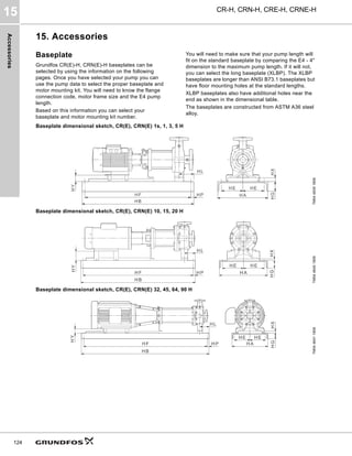
![Accessories
CR-H, CRN-H, CRE-H, CRNE-H
15
125
Baseplate selection
Notes
1. If E4 - 4" > maximum pump length, select XLBP (dimensions are in
inches).
2. XLBP1 = longer version of 139 and 245 baseplate
XLBP2 = longer version of 148 and 252 baseplate
XLBP3 = longer version of 258 and 264 baseplate
XLBP4 = longer version of 153 baseplate
3. HF on long baseplate versions has bolt holes to use existing ANSI
anchor bolts as well as additional bolt holes 1 1/4" from the end.
4. These long baseplates will accommodate all oversize pumps as
listed.
Baseplate
number
NEMA frame Flange size
CR(E), CRN(E) 1s H to CR 20 H
max. pump length
(E4 is the inlet flange to rear motor foot
line)1)
[inches]
CR(E), CRN(E) 32 H to 64 H, CR 90 H
max. pump length
(foot to rear motor hole)1)
[inches]
139 56T-182T GA, GB, GC 27.5 23.5
148 213T-256T GA, GB, GC 37 33
153 286T-364T GA, GB, GC 42 38
245 56T-182T G05-G70 34.5 30.5
252 213T G05-G70 40.5 36.5
258 254T-286T G05-G70 46.5 42.5
264 324T-364T G05-G70 53 49
XLBP12, 3) 56T-182T 139, 245 BP 4) 4)
XLBP22, 3)
213T-256T 148, 252 BP 4) 4)
XLBP32, 3)
254T-364T 258, 264 BP 4) 4)
XLBP42, 3) 284T-364T 153 BP 4) 4)](https://image.slidesharecdn.com/grundfoscr-hcatalog-220705044556-786af359/85/GRUNDFOS-CR-H-Catalog-pdf-125-320.jpg)
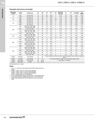
![Accessories
CR-H, CRN-H, CRE-H, CRNE-H
15
127
Baseplate and motor mounting kits
Fig. 63 Baseplate and motor mounting kit
Baseplate Kit description
Product
number
Ship
weight
[lbs]
BP 139
Kit, BP139 56T GA/B/C 97534517 122
Kit, BP139 182T GA/B/C 97534518 118
BP 148
Kit, BP148 213T GA/B/C 97534520 190
Kit, BP148 254T GA/B/C 97534531 200
BP 153
Kit, BP153 284T GA/B/C 97534532 272
Kit, BP153 324T GA/B/C 97534533 264
Kit, BP153 364T GA/B/C 97534534 284
BP 245
Kit, BP245 56T G05/10/50/60/
70/22/33/44
97534535 152
Kit, BP245 182T G05/10/50/60/
70/22/33/44
97534536 150
Kit, BP245 56T G20/30/40 97534537 162
Kit, BP245 182T G20/30/40 97534538 160
BP 252
Kit, BP252 213T G05/10/50/60/
70/22/33/44
97534539 222
Kit, BP252 213T G20/30/40 97534540 228
BP 258
Kit, BP258 254T G05/10/50/60/
70/22/33/44
97534543 299
Kit, BP258 284T G05/10/50/60/
70/22/33/44
97534544 287
Kit, BP258 254T G20/30/40 97534545 307
Kit, BP258 284T G20/30/40 97534546 307
BP 264
Kit, BP264 324T G05/10/50/60/
70/22/33/44
97534548 332
Kit, BP264 364T G05/10/50/60/
70/22/33/44
97534550 356
Kit, BP264 324T G20/30/40 97534571 332
Kit, BP264 364T G20/30/40 97534572 334
XLBP1
Kit, BP139 56T GA/B/C 97534573 167
Kit, BP139 182T GA/B/C 97534574 163
Kit, BP245 56T G05/10/50/60/
70/22/33/44
97534575 180
Kit, BP245 182T G05/10/50/60/
70/22/33/44
97534576 178
Kit, BP245 56T G20/30/40 97534577 190
Kit, BP245 182T G20/30/40 97534578 188
XLBP2
Kit, BP148 213T GA/B/C 97573875 262
Kit, BP148/252 254T GA/B/C 97534579 275
Kit, BP252 213T G05/10/50/60/
70/22/33/44
97573873 278
Kit, BP252 213T G20/30/40 97573874 284
XLBP3
Kit, BP258/264 254T G05/10/
50/60/70/22/33/44
97573876 461
Kit, BP258/264 284T G05/10/
50/60/70/22/33/44
97573877 449
Kit, BP258/264 254T G20/30/40 97573878 469
Kit, BP258/264 284T G20/30/40 97573879 469
Kit, BP258/264 324T G05/10/
50/60/70/22/33/44
97534580 461
Kit, BP258/264 364T G05/10/
50/60/70/22/33/44
97534591 470
Kit, BP258/264 324T G20/30/40 97534592 476
Kit, BP258/264 364T G20/30/40 97534593 463
XLBP4
Kit, BP153 284T GA/B/C 97534594 453
Kit, BP153 324T GA/B/C 97534595 445
Kit, BP153 364T GA/B/C 97534596 465
TM04
4805
2109
Inlet-outlet housing
Motor mounting kit
Baseplate
Volute pad
spacer and pins
(included when
required)](https://image.slidesharecdn.com/grundfoscr-hcatalog-220705044556-786af359/85/GRUNDFOS-CR-H-Catalog-pdf-127-320.jpg)
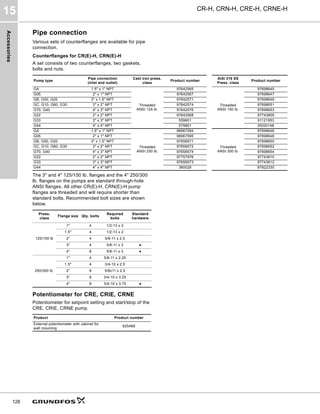
![Accessories
CR-H, CRN-H, CRE-H, CRNE-H
15
129
LiqTec
Description
LiqTec features:
• Protects the pump against dry-running.
• Protects the pump against too high liquid
temperature (+266 °F ± 9 °F (130 °C ± 5 °C)).
• Has a fail-safe design. If the sensor, sensor cable,
electronic unit or power supply fails, the pump stops
immediately.
• The LiqTec is not to be used with the MGFlex motor.
Mounting the LiqTec sensor
The LiqTec can be fitted to a DIN rail to be
incorporated in a control cabinet.
Electrical connection
Example of electrical connection, see page 129.
Calibration of sensor and controller
Follow the procedure on the next page.
Functions
Fig. 64 LiqTec functions
1. Connection for dry-running sensor
2. Connection for external restarting
3. Motor PTC
Green light indicates OK or short-circuited
terminals.
Red light indicates too high motor temperature. The
alarm relay is activated.
4. Connection for PTC sensor
This input is not used in connection with E-pumps
as the variable frequency drive protects the motor
against overload.
5. Sensor indicator light
Red light indicates defective sensor or cable. The
alarm relay is activated.
6. Deactivation of the dry-running monitoring
function
Press the button to deactivate the dry-running
monitoring function. Red flashing light. The PTC
monitoring function is still active.
Press [Restart] to reactivate the dry-running
monitoring function.
7. High liquid temperature indicator light
Red light indicates too high liquid temperature
(+266 °F ± 9 °F (130 °C ± 5 °C)). The alarm relay is
activated.
8. Supply voltage
200-240 VAC, 50/60 Hz and 80-130 VAC 50/60 Hz.
9. Dry-running indicator light
Green light indicates OK (liquid in pump).
Red light indicates dry running (no liquid in pump).
The alarm relay is activated.
10.Alarm/Run relay output
Potential-free changeover contact.
Maximum contact load: 250 V, 1 A, AC (inductive
load).
11.Auto/Man
Changeover between automatic and manual
restarting.
The default setting is "Man".
Changeover is carried out by means of a small
screwdriver.
When "Auto" has been selected, the alarm
indication will automatically be reset 10 to 20
seconds after detection of liquid.
12.Restart
Press [Restart] to restart the pump. The button has
no influence on the PTC monitoring.
TM03
0111
4004](https://image.slidesharecdn.com/grundfoscr-hcatalog-220705044556-786af359/85/GRUNDFOS-CR-H-Catalog-pdf-129-320.jpg)
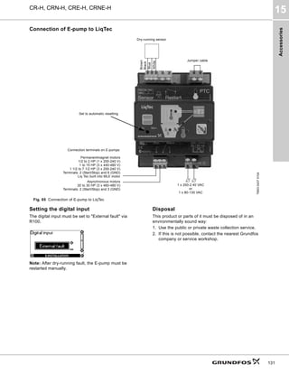
![Accessories
CR-H, CRN-H, CRE-H, CRNE-H
15
132
Pressure sensor
Technical data
Dimensions
Fig. 66 Dimensions RPI transmitter
TM04
7865
2510
Accessory Supplier Type
Pressure range
[psi (bar)]
Product number
EPDM
Product number
FKM
Pressure sensors
Pressure transmitter
with 6 ft screened cable
Connection:
1/4" - 18 NPT
Grundfos RPI
0-87 (0-6) 97748922 97748953
0-145 (0-10) 97748923 97748954
0-232 (0-16) 97748924 97748955
0-362 (0-25) 97748925 97748956
Pressure sensor
Product number
97748922
97748953
97748923
97748954
97748924
97748955
97748925
97748956
Pressure range [psi (bar)] 0-87 (0-6) 0-145 (0-10) 0-232 (0-16) 0-362 (0-25)
Maximum operating pressure [psi (bar)] 870 (60)
Supply voltage 12.5 - 30 VDC
Output signal [mA] 4-20
Load impedance
60 Ω at 12.5 VDC
100 Ω at 13.3 V
Max 900 Ω at 30 VDC
Response time 100 ms typical 50 ms
Resolution
Accuracy
1/1000 FS
+32 to +176 °F +/- 2.0 % FS
-22 to +212 °F +/- 2.5 % FS
Operation temperature -22 to +212 °F (-30 to +100 °C)
Ambient temperature -13 to +140 °F (-25 to 60 °C)
Wetted parts material AISI 316 L
Housing material AISI 316 L
Enclosure IP 67
Weight [lb (kg)] 0.3 (14)
EMC - EN 61326-1
Pressure - mechanical connection Adaptor solution for 1/2" and 1/4" NPT
Markings
TM04
9237
1612
B
A
C
4.33 in.
1.45 in.
ISO 228 - G1/2](https://image.slidesharecdn.com/grundfoscr-hcatalog-220705044556-786af359/85/GRUNDFOS-CR-H-Catalog-pdf-132-320.jpg)
![Accessories
CR-H, CRN-H, CRE-H, CRNE-H
15
133
Pressure sensor
Technical data
Dimensions
Fig. 67 Dimensional sketch
TM05
1533
2911
Accessory Supplier Type
Pressure range
[psi (bar)]
Product number
Pressure sensors
Pressure transmitter
with 6 ft screened cable
Connection: 1/4" - 18 NPT
Danfoss MBS3000
0-87 (0-6) 91136169
0-145 (0-10) 91136170
0-232 (0-16) 91136171
0-362 (0-25) 91136172
0-580 (0-40) 91136173
0-870 (0-60) 91136174
Pressure sensor
Product number 91136169 91136170 91136171 91136172 91136173 91136174
Pressure range [psi (bar)] 0-87 (0-6) 0-145 (0-10) 0-232 (0-16) 0-362 (0-25) 0-580 (0-40) 0-870 (0-60)
Maximum operating pressure [psi (bar)] 300 (20.1) 300 (20.1) 750 (51.7) 1450 (100) 2900 (200) 2900 (200)
Supply voltage 9-32 VDC
Output signal [mA] 4-20
Insulation resistance > 100 MΩ at 100 V
Accuracy, typical +/- FS [%] 0.5 %
Response time, maximum [ms] 4 ms
Medium temperature range [°F (°C)] -40 °F to +185 °F (-40 °C to +85 °C)
Ambient temperature range [°F (°C)] -40 °F to +185 °F (-40 °C to +85 °C)
Wetted parts, material AISI 316L
Housing material AISI 316L
Enclosure rating IP65
Weight [lb (kg)] 0.3 (0.14)
EMC - Emission EN 61000-6-3
EMC Immunity EN 61000-6-2
Pressure connection NPT 1/4-18
CE-marked EMC protected in accordance with EU EMC Directive
TM05
1532
2911](https://image.slidesharecdn.com/grundfoscr-hcatalog-220705044556-786af359/85/GRUNDFOS-CR-H-Catalog-pdf-133-320.jpg)
![Accessories
CR-H, CRN-H, CRE-H, CRNE-H
15
134
Grundfos differential-pressure sensor, DPI
Select the differential-pressure sensor so that the maximum pressure of the sensor is higher than the maximum differential pressure of the pump.
The sensor housing and parts in contact with the liquid
are made of Inox DIN 1.4305 (3) with composite PA top
(2). The connections (4) are DIN 1.4305, 7/16" UNF
connection and gaskets are FKM.
A black and screened cable (1) goes through a
screwed connection PG with M 12 x 1.5 connection.
The sensor is supplied with angular bracket for
mounting on motor or bracket for wall mounting.
A specially coated silicon chip is used for greater
accuracy.
Fig. 68 DPI sensor
Grundfos differential-pressure sensor, DPI
Pressure range
[psi (bar)]
Product number
• 1 sensor incl. 0.9 m screened cable (7/16" connections)
• 1 original DPI bracket (for wall mounting)
• 1 Grundfos bracket (for mounting on motor)
• 2 M4 screws for mounting of sensor on bracket
• 1 M6 screw (self-cutting) for mounting on 3 HP and smaller
• 1 M8 screw (self-cutting) for mounting on 5-10 HP
• 1 M10 screw (self-cutting) for mounting on 15-25 HP
• 1 M12 screw (self-cutting) for mounting on 30 HP
• 3 capillary tubes (short/long)
• 2 fittings (1/4" - 7/16")
• 5 cable clips (black)
• Installation and operating instructions
0 - 8.7 (0 - 0.6) 96611522
0 - 14.5 (0 - 1.0) 96611523
0-23 (0 - 1.6) 96611524
0-36 (0 - 2.5) 96611525
0-58 (0 - 4.0) 96611526
0-87 (0 - 6.0) 96611527
0-145 (0-10) 96611550
TM03
2057
3505
P2
P1
3
2
4
1](https://image.slidesharecdn.com/grundfoscr-hcatalog-220705044556-786af359/85/GRUNDFOS-CR-H-Catalog-pdf-134-320.jpg)
![Accessories
CR-H, CRN-H, CRE-H, CRNE-H
15
135
Technical data
Dimensions
Fig. 69 Dimensional sketch
Fig. 70 Wiring
Grundfos differential-pressure sensor, DPI
Product number 96611522 96611523 96611524 96611525 96611526 96611527 96611550
Pressure ranges, differential pressure [psi (bar)]
0 - 8.7
(0 - 0.6)
0 - 14.5
(0 - 1.0)
0-23
(0 - 1.6)
0-36
(0 - 2.5)
0-58
(0 - 4.0)
0-87
(0 - 6.0)
0-145
(0-10)
Supply voltage 12-30 VDC
Output signal 4-20 mA
Load [Ω] 24 V: max. 500 [Ω], 16 V: max. 200 [Ω], 12 V: max. 100 [Ω]
Maximum system pressure, P1 and P2 simultaneously
[psi (bar)]
232 (16)
Rupture pressure [bar] 1.5 x system pressure
Measuring accuracy 2.5 % BFSL
Response time < 0.5 seconds
Liquid temperature range +14 °F to +158 °F (-10 °C to +70 °C)
Storage temperature range -40 °F to +176 °F (-40 °C to +80 °C)
Electrical connection 26 GA, 3 ft cable - M12 x 1.5 in sensor top
Short circuit-proof Yes
Protected against reverse polarity Yes
Over supply voltage Yes
Materials in contact with liquid DIN 1.4305 FKM and PPS
Enclosure class IP55
Weight [lb] 1.2
EMC (electromagnetic compatibility) According to EN 60335-1
Emission/immunity According to EN 61800-3
Connections 7/16"-UNF
Sealing material FKM
TM03
2059
3505
TM03
2225
3905
1
12-30 V supply
voltage
Brown
2
GND (earth
conductor)
Yellow
3 Signal conductor Green
4
Test conductor (can
be cut off during
mounting). This
conductor must not
be connected to the
power supply.
White
E
C
D
B
A
F
P2
P1
∅1.77
0.55"
0.24"
3.03"](https://image.slidesharecdn.com/grundfoscr-hcatalog-220705044556-786af359/85/GRUNDFOS-CR-H-Catalog-pdf-135-320.jpg)
![Accessories
CR-H, CRN-H, CRE-H, CRNE-H
15
136
Grundfos differential-pressure sensor, DPI g.2 version
Select the differential-pressure sensor so that the maximum pressure of the sensor is higher than the maximum differential pressure of the pump.
All materials used for DPI 2 are 316 L.
Fitting connection for capillary tube is 7/16" UNF.
Cable with M12 x 4 connector.
Sensor is supplied with fitting for capillary tubing.
Measuring technology is based on Coated Silicon
Chip.
Fig. 71 DPI sensor g.2 version
TM04
7866
2410
Grundfos differential-pressure sensor, DPI g.2 version
Pressure range
[psi (bar)]
Product number
• 1 sensor
• 1 capillary tube short version
• 1 fitting for capillary tube
• 6 ft (1.8 m) cable
• 1 installation and operation instructions
0 - 8.7 (0 - 0.6) 97747194
0 - 14.5 (0 - 1.0) 97747195
0-23 (0 - 1.6) 97747196
0-36 (0 - 2.5) 97747197
0-58 (0 - 4.0) 97747198
0-87 (0 - 6.0) 97747199
0-145 (0-10) 97747200
TM04
9237
3710
B
A
C
4.33
in.
(110
mm)
1.46 in.
(36.95 mm)](https://image.slidesharecdn.com/grundfoscr-hcatalog-220705044556-786af359/85/GRUNDFOS-CR-H-Catalog-pdf-136-320.jpg)
![Accessories
CR-H, CRN-H, CRE-H, CRNE-H
15
137
Technical data
Dimensions
Fig. 72 DPI sensor g.2 version
Electrical connections
Fig. 73 Electrical connections
* Common ground for both pressure and temperature signal.
* Power supply (screened cable): SELV or PELV.
Grundfos differential-pressure sensor, DPI g.2 version
Product number 97747194 97747195 97747196 97747197 97747198 97747199 97747200
Pressure ranges, differential pressure [psi (bar)]
0 - 8.7
(0 - 0.6)
0 - 14.5
(0 - 1.0)
0-23
(0 - 1.6)
0-36
(0 - 2.5)
0-58
(0 - 4.0)
0-87
(0 - 6.0)
0-145
(0-10)
Supply voltage 12-30 VDC
Output signal 4-20 mA
Load [Ω] 30 V DC: max. 900 ohms [Ω], 1.3 V: max. 100 [Ω], 12.5 V: max. 60 [Ω]
Maximum system pressure, P1 and P2 simultaneously
[psi (bar)]
870 (60)
Rupture pressure [bar] 1.5 x system pressure
Measuring accuracy 2.0 % FS
Response time < 100 ms (typical 50 ms)
Liquid temperature range -22 to +212 °F (-30 to +100 °C)
Storage temperature range -67 to +158 °F (-55 to +70 °C)
Electrical connection 27 ga, 6 ft (1.8) cable M 12 x 4
Short circuit-proof Yes
Protected against reverse polarity Yes
Over supply voltage Yes
Materials in contact with liquid AISI 316 L
Enclosure class IP67
Weight [lb] 1.2
EMC (electromagnetic compatibility) According to EN 61326-1
Connections 7/16"-UNF
Sealing material EPDM
TM04
9237
3710
B
A
C
4.33
in.
(110
mm)
1.46 in.
(36.95 mm)
TM04
7156
1610
PIN 1 2 3 4
Wire color Brown Grey Blue Black
Output
4-20 mA
+ Not used - Not used
Output
2 x 0-10 V
+ Pressure signal -*
Temperature
signal
1
3
4
2](https://image.slidesharecdn.com/grundfoscr-hcatalog-220705044556-786af359/85/GRUNDFOS-CR-H-Catalog-pdf-137-320.jpg)
![Accessories
CR-H, CRN-H, CRE-H, CRNE-H
15
138
Flow transmitters
• Flow tube in AISI 316 mounted with transmitter
• Transmitter AISI 316 L
• 4-20 mA output signal
• 2 x flanges
• 15 ft cable free ends
• quick guide.
For more information about the VFI sensor, see the Grundfos Direct Sensors data booklet, publication number 97790189, at www.grundfos.com
(Grundfos Product Center).
Gauges for CRE, CRIE, CRNE
TM04
7362
2210
Type
Flow range
[gpm]
Connection
O-ring Flange material Product
number
EPDM FKM Cast iron Stainless
VFI 0.3-6
1.3 - 26 3/4" ● ● 97686127
1.3 - 2.6 3/4" ● ● 97688293
VFI 0.6-12
2.6 - 53 1" ● ● 97686129
2.6 - 53 1" ● ● 97688295
VFI 1.3-25
5.7 - 110 1 1/4" ● ● 97686141
5.7 - 110 1 1/4" ● ● 97688297
VFI 2-40
8.8 - 176 1 3/4" ● ● 97686143
8.8 - 176 1 3/4" ● ● 97688299
VFI 3.2-64
14-282 2" ● ● 97686145
14-282 2" ● ● 97688301
VFI 5.2-104 23-458 2 1/2" ● ● 96788476
VFI 8-160 35-704 3" ● ● 97788478
VFI 8-160 53-1060 4" ● ● 97788492
Accessory Measuring range Product number
Liquid filled pressure gauge
• AISI 304/Copper
30" Hg - 30 psi 91123566
0-60 psi 00ID8562
0-100 psi 00ID8563
0-160 psi 00ID8564
0-200 psi 00ID8565
0-300 psi 00ID8566
0-400 psi 00ID8567
0-600 psi 00ID8568
Liquid filled pressure gauge
• AISI 316
30" Hg - 30 psi 91130835
0-60 psi 00ID8569
0-100 psi 00ID8570
0-160 psi 00ID8571
0-200 psi 00ID8572
0-300 psi 00ID8573
0-400 psi 00ID8574
0-600 psi 00ID8575
0-200 psi 00ID8576](https://image.slidesharecdn.com/grundfoscr-hcatalog-220705044556-786af359/85/GRUNDFOS-CR-H-Catalog-pdf-138-320.jpg)
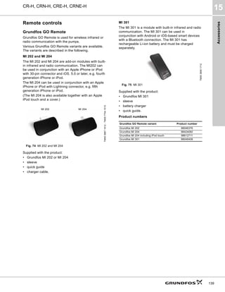
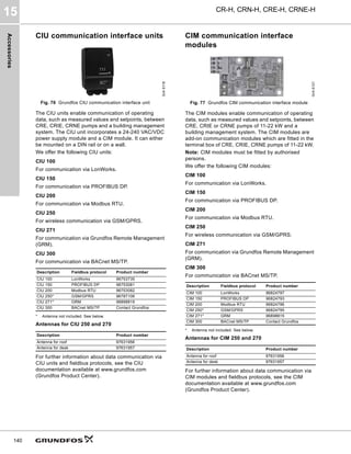
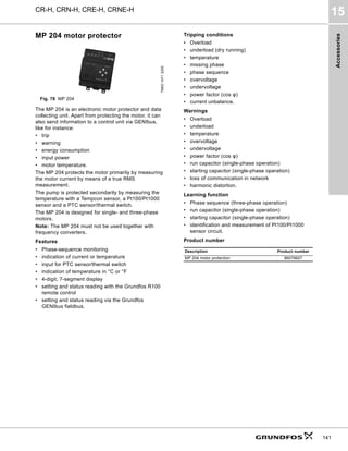
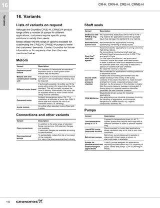
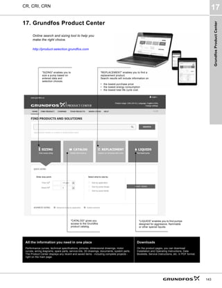

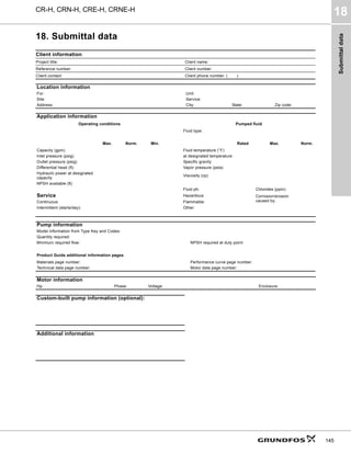
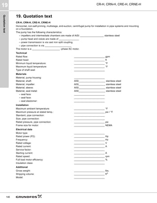


The document is a product guide for Grundfos CR-H, CRN-H, CRE-H, and CRNE-H horizontal end-suction multistage centrifugal pumps, detailing their features, performance ranges, and applications. It explains the difference between standard and e-pumps with built-in frequency control, highlighting their operational advantages and selection criteria. Additionally, the guide includes technical data, motor specifications, installation guidelines, and various available accessories.


