Download to read offline

![Product
data
5
Hydro MPC, ASEAN range
2
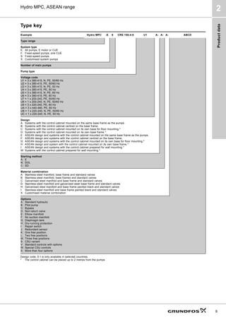
2. Product data
Performance range
TM06
3290
5014
4PñK@
+
P@
+GUR03(6
+]
,62$QQH[$
5
5
5
5
5,
5,
5,
5,
5,
[
[
[ [
[
[
[
[
[](https://image.slidesharecdn.com/grundfoshydrompccatalog-220705055457-497630e1/85/Grundfos-Hydro-MPC-Catalog-pdf-5-320.jpg)
![Product
data
6
Hydro MPC, ASEAN range
2
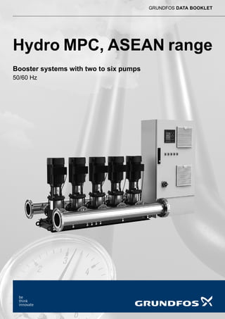
Product range, 50 Hz
● Available as standard.
❍ Available on request.
1) Higher temperature available on request.
2)
Booster systems with a maximum operating pressure higher than 16 bar are available on request.
3)
The pressure will be almost constant between Hset and Hstop. For further information, see page 14.
4) Requires that a flowmeter has been installed and connected.
5)
In some regions, galvanised manifolds are available as an option. For further information, contact Grundfos.
6)
CRN: EN/DIN 1.4401 / AISI 316.
TM03
0993
0905
TM03
0999
0905
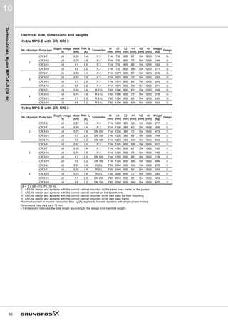
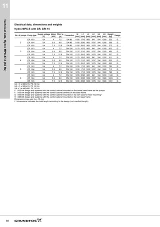
Control variant Hydro MPC-E Hydro MPC-S
Frequency 50 Hz 50 Hz
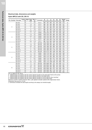
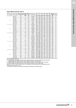
Hydraulic data
Maximum head [m] 144 144
Flow rate [m3/h] 0-720 0-720
Liquid temperature [°C] 0-601)
0-60
Maximum operating pressure [bar] 162)
162)
Motor data
Number of pumps 2-6 2-6
Motor power [kW] 0.37 - 30 0.37 - 30
Shaft seal
HQQE (SiC/SiC/EPDM) ● ●
Materials
CRI/CRN 3 to CRI/CRN 90:
Stainless steel EN/DIN 1.4301/AISI 3046) ❍ ❍
CR 3 to CR 90:
Cast iron and stainless steel EN/DIN
1.4301/AISI 304
● ●
Manifold: Stainless steel5)
● ●
Pipework connection
Union connection R 2 to R 2 1/2 R 2 to R 2 1/2
DIN flange DN 80 to DN 350 DN 80 to DN 350
Functions
Constant-pressure control ● ● 3)
Automatic cascade control ● ●
Pump changeover/alternation ● ●
Stop function ● -
Proportional-pressure control ● -
Bus communication (external) ❍ ❍
Integrated frequency converter (in pump) ● -
External frequency converter (in cabinet) ● -
Ethernet connection ● ●
Alternative setpoints ● ●
Redundant primary sensor (option) ● ●
Standby pump ● ●
Emergency run ● ●
Specific energy calculation ●4) -
Log function ● ●
Reduced operation ● ●
Service contact information ● ●
Help texts ● ●
PT PT](https://image.slidesharecdn.com/grundfoshydrompccatalog-220705055457-497630e1/85/Grundfos-Hydro-MPC-Catalog-pdf-6-320.jpg)
![Product
data
7
Hydro MPC, ASEAN range
2
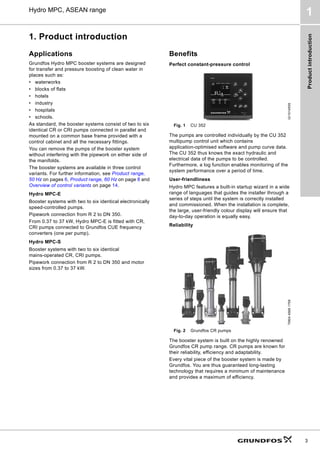
Performance range
TM06
3292
5014
4PñK@
+
P@
+GUR03(6
+]
,62$QQH[$
5
5
5
5
5
5
5
5
5
[
[
[
[
[
[
[
[
[](https://image.slidesharecdn.com/grundfoshydrompccatalog-220705055457-497630e1/85/Grundfos-Hydro-MPC-Catalog-pdf-7-320.jpg)
![Product
data
8
Hydro MPC, ASEAN range
2
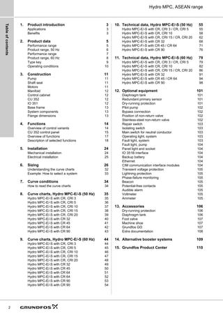
Product range, 60 Hz
● Available as standard.
❍ Available on request.
1)
Higher temperature available on request.
2) Booster systems with a maximum operating pressure higher than 16 bar are available on request.
3)
The pressure will be almost constant between Hset and Hstop. For further information, see page 14.
4)
Requires that a flowmeter has been installed and connected.
5) In some regions, galvanised manifolds are available as an option. For further information, contact Grundfos.
6)
CRN: EN/DIN 1.4401 / AISI 316.
TM03
0993
0905
TM03
0999
0905
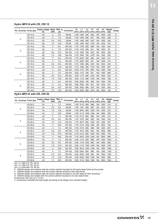
Control variant Hydro MPC-E Hydro MPC-S
Frequency 60 Hz 60 Hz
Hydraulic data
Maximum head [m] 144 144
Flow rate [m3
/h] 0-876 0-876
Liquid temperature [°C] 0-601) 0-601)
Maximum operating pressure [bar] 162)
162)
Motor data
Number of pumps 2-6 2-6
Motor power [kW] 0.37 - 37 0.37 - 37
Shaft seal
HQQE (SiC/SiC/EPDM) ● ●
Materials
CRI/CRN 3 to CRI/CRN 90:
Stainless steel EN/DIN 1.4301/AISI 3046) ● ●
CR 3 to CR 90:
Cast iron and stainless steel EN/DIN
1.4301/AISI 304
● ●
Manifold: Stainless steel5)
● ●
Pipework connection
Union connection R 2 to R 2 1/2 R 2 to R 2 1/2
DIN flange DN 80 to DN 350 DN 80 to DN 350
Functions
Constant-pressure control ● ● 3)
Automatic cascade control ● ●
Pump changeover/alternation ● ●
Stop function ● -
Proportional-pressure control ● -
Bus communication (external) ❍ ❍
Integrated frequency converter (in pump) ● -
External frequency converter (in cabinet) ● -
Ethernet connection ● ●
Alternative setpoints ● ●
Redundant primary sensor (option) ● ●
Standby pump ● ●
Emergency run ● ●
Specific energy calculation ● 4) -
Log function ● ●
Reduced operation ● ●
Service contact information ● ●
Help texts ● ●
PT PT](https://image.slidesharecdn.com/grundfoshydrompccatalog-220705055457-497630e1/85/Grundfos-Hydro-MPC-Catalog-pdf-8-320.jpg)


![Functions
23
Hydro MPC, ASEAN range
4
Soft pressure build-up
Fig. 29 Soft pressure build-up
This function ensures a soft start of systems with for
instance empty pipework.
It has two phases:
1. The pipework is slowly filled with water.
2. When the pressure sensor of the system detects
that the pipework has been filled with water, the
pressure is increased until it reaches the setpoint.
See fig. 30.
Fig. 30 Filling and pressure build-up phases
You can use the function to prevent water hammer in
high-rise buildings with unstable power supply or in
irrigation systems.
Emergency run
Fig. 31 Emergency run
This function is especially suited for important systems
where the operation must not be interrupted.
The function will keep all pumps running regardless of
warnings or alarms. The pumps will run according to a
setpoint set specifically for this function.
Reduced operation
This function makes it possible to reduce the operation
of the system via a digital input. The function is used in
applications where the mains power is sometimes
switched to generator power. To avoid using more
power than the generator can deliver, the system can
be derated via a digital input.
TM03
9037
3207
1. Filling phase 2. Pressure build-up phase
H [m]
Filling time Ramp time
Time [sec]](https://image.slidesharecdn.com/grundfoshydrompccatalog-220705055457-497630e1/85/Grundfos-Hydro-MPC-Catalog-pdf-23-320.jpg)


![Sizing
28
Hydro MPC, ASEAN range
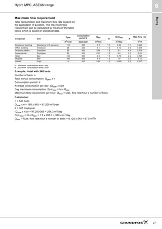
6
Required discharge pressure
You can calculate the required discharge pressure,
pset, of the booster system with the following equation:
Key
Fig. 34 Calculation of required discharge pressure
Calculation
System layout
What is the system layout?
a) Direct boosting
Example: Booster system connected to water mains
designed to distribute water from one place to
another.
b) Break tank
Example: Booster system connected to a break tank
installed before the booster system.
c) Pressure boosting in zones
Example: High-rise building or hilly landscape
where the water supply system is divided into
zones.
d) Roof tank
Example: Booster system distributes water to a roof
tank on top of a high-rise building.
Consumption profile and load profile
The consumption pattern of the installation can be
illustrated as a 24-hour consumption profile and a load
profile.
24-hour consumption profile
The 24-hour consumption profile is the relation
between the time of the day and the flow rate.
Fig. 35 Example of 24-hour consumption profile
Note: If the consumption is variable and optimum
comfort is required, pumps with continuously variable
speed control should be used.
pset = ptap(min) + pf + (hmax/10.2)
pboost = pset - pin(min)
pset = Required discharge pressure in bar
ptap(min) = Required minimum pressure at the
highest tapping point in bar
pf = Total pipe friction loss in metres
hmax = Height from booster discharge port to
highest tapping point in metres
pin(min) = Minimum inlet pressure in bar
pboost = Required boost in bar
TM04
4105
0709
Ptap(min)
hmax
P
P
P
P
f
in(min)
boost
set
ptap(min)
hmax
pf
pin(min)
pboost
pset
ptap(min) = 2 bar
pf = 1.2 bar
hmax = 41.5 metres
pin(min) = 2 bar
pset = 2 + 1.2 + (41.5/10.2) = 7.3 bar
pboost = 7.3 - 2 = 5.3 bar
TM00
9188
1303
24
21
18
15
12
9
6
10
20
30
40
[ m3 /h ]
Q
3](https://image.slidesharecdn.com/grundfoshydrompccatalog-220705055457-497630e1/85/Grundfos-Hydro-MPC-Catalog-pdf-28-320.jpg)
![Sizing
30
Hydro MPC, ASEAN range
6
Inlet pressure
Is there a positive inlet pressure? If so, the inlet
pressure must be taken into consideration to ensure
safe operation.
If there is a positive inlet pressure, this has to be
added to the discharge pressure supplied by the
booster system in order to evaluate the resulting
maximum discharge pressure.
Example
A Hydro MPC-E booster system with three CRI 20-7
pumps has been selected.
Maximum operating pressure: 16 bar.
Maximum inlet pressure: 10 bar.
Discharge pressure against a closed valve: 10 bar.
The selected system is allowed to start at an inlet
pressure of maximum 5.8 bar, as the maximum
operating pressure is limited to 16 bar. If the maximum
inlet pressure exceeds 5.8 bar, a system rated PN 25
must be selected.
Selection of booster system
Select the booster system on the basis of these
factors: maximum flow requirement, required
discharge pressure, load profile, number of pumps
required, possible standby pumps, etc.
Accessories
Having selected the optimum booster system, you
must consider whether accessories as those
mentioned below are required.
Dry-running protection
Every booster system must be protected against dry
running.
The inlet conditions determine the type of dry-running
protection:
• If the system draws water from a tank or a well,
select a level switch or an electrode relay for
dry-running protection.
• If the system has an inlet pressure, select a
pressure transmitter or a pressure switch for
dry-running protection.
Pilot pump
If you select a pilot pump, it must be sized according to
the size of the main pumps in the system. As a rule of
thumb, the pilot pump should not be smaller than 1/5 of
the flow of a main pump at the desired setpoint.
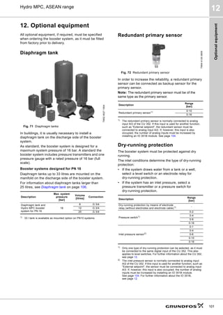
Diaphragm tank
The need for a diaphragm tank is estimated on the
basis of the following guidelines:
• Due to the stop function, all booster systems in
buildings must be equipped with a diaphragm tank.
• Normally, the booster systems in water supply
applications require no diaphragm tank, as miles of
piping partly hold the necessary capacity, partly
have the elasticity to give sufficient capacity.
Note: To avoid the risk of water hammer, a
diaphragm tank may be necessary.
• The need for a diaphragm tank for the booster
systems in industrial applications should be
estimated from situation to situation on the basis of
the individual factors on site.
Note: If the booster system includes pilot pumps, the
diaphragm tank is to be sized according to the capacity
of this pump.
For further information about optional equipment and
accessories, see pages 146 to 153.
Pump type
Recommended diaphragm tank size
[litres]
-E -S
CR, CRI, CRE, CRIE 3 8 80
CR, CRI, CRE, CRIE 5 12 120
CR, CRI, CRE, CRIE 10 18 180
CR, CRI, CRE, CRIE 15 80 300
CR, CRI, CRE, CRIE 20 80 400
CR, CRE 32 80 600
CR, CRE 45 120 800
CR, CRE 64 120 1000
CR, CRE 90 180 1500
CR, CRE 120 300 1500
CR, CRE 150 400 1500](https://image.slidesharecdn.com/grundfoshydrompccatalog-220705055457-497630e1/85/Grundfos-Hydro-MPC-Catalog-pdf-30-320.jpg)
![Sizing
31
Hydro MPC, ASEAN range
6
You can calculate the size of the obligatory diaphragm
tank in litres from the following equations:
Hydro MPC-E
Hydro MPC-S
Hydro MPC-E
Hydro MPC-S
The tank values are based on the following data:
Example of Hydro MPC-E and -S with CRI 20
V0 =
kQ × Q x (pset + 1)2
x
3.6 x (kf x pset + 1) x kH x pset
V0 =
1000 x Q x (pset + 1) x (kH x pset + pset + 1)
4 x N x (kf x pset + 1) x kH x pset
Symbol Description
V0 Tank volume [litres]
kQ
The ratio between rated flow rate of one pump Qnom and
the flow rate Qmin at which the pump is to change to
on/off operation.
kQ = Qmin/Qnom
Q Mean flow rate, Qnom [m3
/h]
pset Setpoint [bar]
kH
The ratio between the on/off band ΔH and the setpoint
pset, kH = ΔH/pset
kf
The ratio between tank pre-charge pressure p0 and the
setpoint pset
kf = p0/pset
0.9 for Hydro MPC-S
0.7 for Hydro MPC-E and -F
N Maximum number of starts/stops per hour.
TM03
3070
0206
TM03
3071
0206
3600
N
------------
- 10
–
H
Q
Qmin
pset + 1/2 ΔH
pset - 1/2 ΔH
pset
ΔH
Qnom
H
Q
pset + ΔH
pset
Qnom
ΔH
Symbol
Hydro MPC
-E -S
Q Qnom of one pump Qnom of one pump
kQ 10 % -
pset 4 bar 4 bar
kH 20 % 25 %
kf 0.7 0.9
Symbol Hydro MPC-E Hydro MPC-S
Q [m3
/h] 10 10
kQ 10 % -
kH 20 % 25 %
pset [bar] 4 4
N [h-1] 200 100
Result
V0 [litres] 18.3 163
Selected tank 18 180
ΔH [bar] 0.8 1
p0 [bar] 2.8 3.6](https://image.slidesharecdn.com/grundfoshydrompccatalog-220705055457-497630e1/85/Grundfos-Hydro-MPC-Catalog-pdf-31-320.jpg)
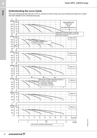


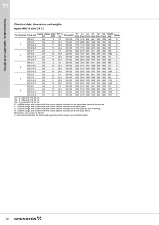
![+]
,62$QQH[$
Specification of booster system, pump type,
frequency and of the standard to which the
QH-curves correspond.
The y-axis is adapted to the
individual pump type.
Specification of system performance based on
the number of pumps in operation:
1 = one pump in operation
2 = two pumps in operation
3 = three pumps in operation.
The x-axis is common to all pump types.](https://image.slidesharecdn.com/grundfoshydrompccatalog-220705055457-497630e1/85/Grundfos-Hydro-MPC-Catalog-pdf-39-320.jpg)
![Sizing
33
Hydro MPC, ASEAN range
6
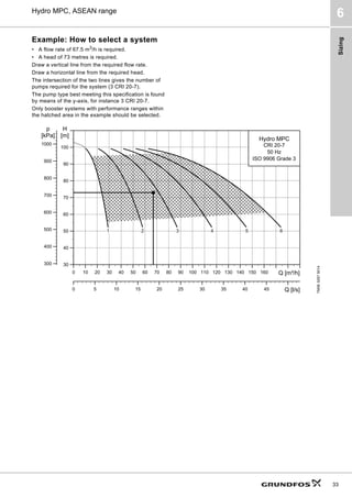
Example: How to select a system
• A flow rate of 67.5 m3
/h is required.
• A head of 73 metres is required.
Draw a vertical line from the required flow rate.
Draw a horizontal line from the required head.
The intersection of the two lines gives the number of
pumps required for the system (3 CRI 20-7).
The pump type best meeting this specification is found
by means of the y-axis, for instance 3 CRI 20-7.
Only booster systems with performance ranges within
the hatched area in the example should be selected.
TM06
3297
5014
4PñK@
P@
+
N3D@
S
4OV@
+GUR03
5,
+]
,62*UDGH](https://image.slidesharecdn.com/grundfoshydrompccatalog-220705055457-497630e1/85/Grundfos-Hydro-MPC-Catalog-pdf-40-320.jpg)


![+]
,62$QQH[$](https://image.slidesharecdn.com/grundfoshydrompccatalog-220705055457-497630e1/85/Grundfos-Hydro-MPC-Catalog-pdf-47-320.jpg)


![+]
,62$QQH[$](https://image.slidesharecdn.com/grundfoshydrompccatalog-220705055457-497630e1/85/Grundfos-Hydro-MPC-Catalog-pdf-55-320.jpg)


![+]
,62$QQH[$](https://image.slidesharecdn.com/grundfoshydrompccatalog-220705055457-497630e1/85/Grundfos-Hydro-MPC-Catalog-pdf-62-320.jpg)

![+]
,62$QQH[$](https://image.slidesharecdn.com/grundfoshydrompccatalog-220705055457-497630e1/85/Grundfos-Hydro-MPC-Catalog-pdf-69-320.jpg)
![+]
,62$QQH[$
4PñK@
P@
+
4OV@
N3D@
S
5,](https://image.slidesharecdn.com/grundfoshydrompccatalog-220705055457-497630e1/85/Grundfos-Hydro-MPC-Catalog-pdf-74-320.jpg)
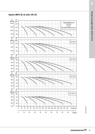
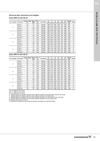
![Curve
charts,
Hydro
MPC-E/-S
(50
Hz)
40
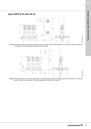
8
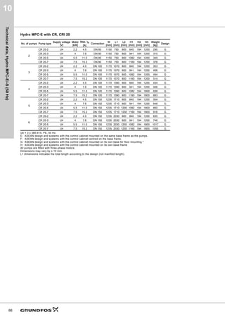
Hydro MPC-E/-S with CR 32
TM06
2941
5014
4PñK@
+
P@
S
N3D@
4OV@
5
4PñK@
P@
+
N3D@
S
5
4PñK@
P@
+
N3D@
S
5
4PñK@
P@
+
N3D@
S
5
4PñK@
P@
+
N3D@
S
+GUR03(6
5
+]
,62$QQH[$](https://image.slidesharecdn.com/grundfoshydrompccatalog-220705055457-497630e1/85/Grundfos-Hydro-MPC-Catalog-pdf-75-320.jpg)
![Curve
charts,
Hydro
MPC-E/-S
(50
Hz)
41
8
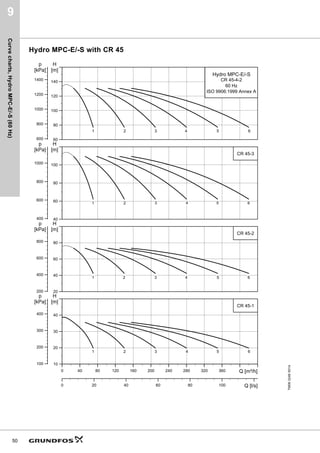
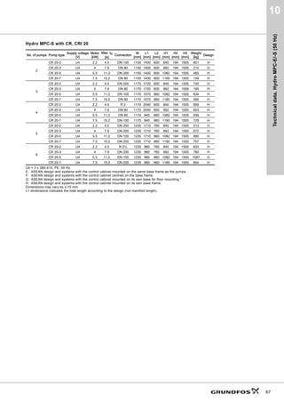
Hydro MPC-E/-S with CR 45
TM06
2942
5014
4PñK@
+
P@
S
N3D@
4OV@
5
4PñK@
P@
+
N3D@
S
5
4PñK@
P@
+
N3D@
S
5
4PñK@
P@
+
N3D@
S
5
4PñK@
P@
+
N3D@
S
+GUR03(6
5
+]
,62$QQH[$](https://image.slidesharecdn.com/grundfoshydrompccatalog-220705055457-497630e1/85/Grundfos-Hydro-MPC-Catalog-pdf-76-320.jpg)
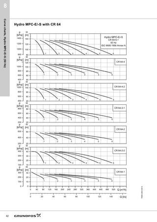
![Curve
charts,
Hydro
MPC-E/-S
(50
Hz)
42
8
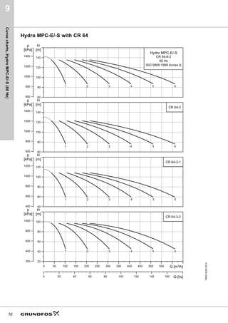
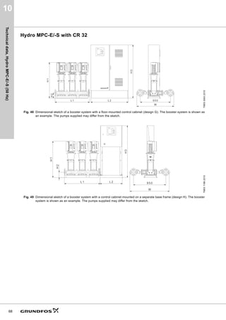
Hydro MPC-E/-S with CR 64
TM06
2943
5014
4PñK@
+
P@
S
N3D@
4OV@
5
4PñK@
P@
+
N3D@
S
5
4PñK@
P@
+
N3D@
S
5
4PñK@
P@
+
N3D@
S
5
4PñK@
P@
+
N3D@
S
5
4PñK@
P@
+
N3D@
S
+GUR03(6
5
+]
,62$QQH[$
4PñK@
P@
+
N3D@
S
5](https://image.slidesharecdn.com/grundfoshydrompccatalog-220705055457-497630e1/85/Grundfos-Hydro-MPC-Catalog-pdf-77-320.jpg)
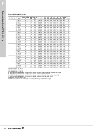
![Curve
charts,
Hydro
MPC-E/-S
(50
Hz)
43
8
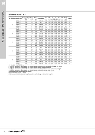
Hydro MPC-E/-S with CR 90
TM06
2944
5014
4PñK@
+
P@
S
N3D@
5
4PñK@
P@
+
4OV@
N3D@
S
5
4PñK@
P@
+
N3D@
S
5
4PñK@
P@
+
N3D@
S
5
4PñK@
P@
+
N3D@
S
5
4PñK@
P@
+
N3D@
S
5
4PñK@
P@
+
N3D@
S
+GUR03(6
5
+]
,62$QQH[$](https://image.slidesharecdn.com/grundfoshydrompccatalog-220705055457-497630e1/85/Grundfos-Hydro-MPC-Catalog-pdf-78-320.jpg)
![+]
,62$QQH[$
4PñK@
P@
+
N3D@
S
5,](https://image.slidesharecdn.com/grundfoshydrompccatalog-220705055457-497630e1/85/Grundfos-Hydro-MPC-Catalog-pdf-80-320.jpg)


![+]
,62$QQH[$](https://image.slidesharecdn.com/grundfoshydrompccatalog-220705055457-497630e1/85/Grundfos-Hydro-MPC-Catalog-pdf-87-320.jpg)


![+]
,62$QQH[$](https://image.slidesharecdn.com/grundfoshydrompccatalog-220705055457-497630e1/85/Grundfos-Hydro-MPC-Catalog-pdf-94-320.jpg)

![+]
,62$QQH[$](https://image.slidesharecdn.com/grundfoshydrompccatalog-220705055457-497630e1/85/Grundfos-Hydro-MPC-Catalog-pdf-99-320.jpg)
![+]
,62$QQH[$](https://image.slidesharecdn.com/grundfoshydrompccatalog-220705055457-497630e1/85/Grundfos-Hydro-MPC-Catalog-pdf-105-320.jpg)
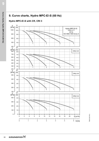
![Curve
charts,
Hydro
MPC-E/-S
(60
Hz)
49
9
Hydro MPC-E/-S with CR 32
TM06
3245
5014
4PñK@
+
P@
S
N3D@
4OV@
5
4PñK@
P@
+
N3D@
S
5
4PñK@
P@
+
N3D@
S
5
4PñK@
P@
+
N3D@
S
5
4PñK@
P@
+
N3D@
S
+GUR03(6
5
+]
,62$QQH[$](https://image.slidesharecdn.com/grundfoshydrompccatalog-220705055457-497630e1/85/Grundfos-Hydro-MPC-Catalog-pdf-106-320.jpg)
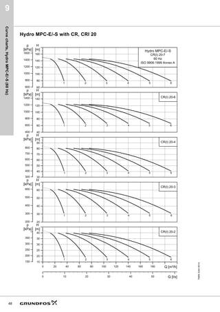
![Curve
charts,
Hydro
MPC-E/-S
(60
Hz)
50
9
Hydro MPC-E/-S with CR 45
TM06
3246
5014
4PñK@
P@
+
N3D@
S
4OV@
5
4PñK@
P@
+
N3D@
S
5
4PñK@
P@
+
N3D@
S
5
4PñK@
P@
+
N3D@
S
+GUR03(6
5
+]
,62$QQH[$](https://image.slidesharecdn.com/grundfoshydrompccatalog-220705055457-497630e1/85/Grundfos-Hydro-MPC-Catalog-pdf-107-320.jpg)
![Curve
charts,
Hydro
MPC-E/-S
(60
Hz)
51
9
Hydro MPC-E/-S with CR 64
TM06
3247
5014
4PñK@
+
P@
S
N3D@
5
4PñK@
P@
+
4OV@
N3D@
S
5
4PñK@
P@
+
N3D@
S
5
4PñK@
P@
+
N3D@
S
+GUR03(6
5
+]
,62$QQH[$
4PñK@
P@
+
N3D@
S
5](https://image.slidesharecdn.com/grundfoshydrompccatalog-220705055457-497630e1/85/Grundfos-Hydro-MPC-Catalog-pdf-108-320.jpg)
![Curve
charts,
Hydro
MPC-E/-S
(60
Hz)
52
9
Hydro MPC-E/-S with CR 64
TM06
3248
5014
4PñK@
+
P@
S
N3D@
5
4PñK@
P@
+
4OV@
N3D@
S
5
4PñK@
P@
+
N3D@
S
5
4PñK@
P@
+
N3D@
S
+GUR03(6
5
+]
,62$QQH[$](https://image.slidesharecdn.com/grundfoshydrompccatalog-220705055457-497630e1/85/Grundfos-Hydro-MPC-Catalog-pdf-109-320.jpg)
![Curve
charts,
Hydro
MPC-E/-S
(60
Hz)
53
9
Hydro MPC-E/-S with CR 90
TM06
3256
5014
4PñK@
P@
+
N3D@
S
5
4PñK@
P@
+
N3D@
S
5
4PñK@
P@
+
N3D@
S
+GUR03(6
5
+]
,62$QQH[$
4PñK@
P@
+
N3D@
S
4OV@
5](https://image.slidesharecdn.com/grundfoshydrompccatalog-220705055457-497630e1/85/Grundfos-Hydro-MPC-Catalog-pdf-110-320.jpg)
![Curve
charts,
Hydro
MPC-E/-S
(60
Hz)
54
9
Hydro MPC-E/-S with CR 90
TM06
3257
5014
4PñK@
P@
+
N3D@
S
4OV@
5
4PñK@
P@
+
N3D@
S
5
4PñK@
P@
+
N3D@
S
+GUR03(6
5
+]
,62$QQH[$](https://image.slidesharecdn.com/grundfoshydrompccatalog-220705055457-497630e1/85/Grundfos-Hydro-MPC-Catalog-pdf-111-320.jpg)


The Grundfos Hydro MPC booster systems are designed for pressure boosting of clean water in various applications such as hotels, industries, and schools, featuring configurations with two to six identical pumps. These systems are equipped with advanced control features for optimal efficiency, including constant-pressure control and user-friendly interfaces for installation and operation. Variants are available for different power specifications and operating conditions, ensuring flexibility and reliability in various environments.