Download to read offline


![1
ELECTRIC SELF PRIMING CENTRIFUGAL PUMPS WITH BUILT-IN EJECTOR
Series M 50-60-70-80-300-400-500
USES:
They are used in the supply of clean water and non-aggressive
chemical liquids, in the irrigation of orchards and gardens.
particularly suited for domestic systems and automatic
distribution of water by small or medium sized hydro-
pneumatic pressure tanks or automatic pressure controllers.
FEATURES:
- Pump body: Cast iron
- Impeller: Thermoplastic resin
- Shaft: Stainless steel Aisi-43
- Mechanical seal: Carbon / Ceramic
- Motor protected to: IP 44
On request IP55
- Standard tension: 1x230V-50Hz
3x230V/400V
- Max. flow rate [m3/h]: 10
- Max. head [m]: 92
- Max. working pressure [bar]: 8
- Max. Tº pumped liquid [ºC]: -15 / +50
- Max. Enviroment Tº [ºC]: +40
- Max. suction lift [m]: 8-9 with foot valve
- Installation: Horizontal
Type DNA DNM f a n1 n2 H h1 h2 w Ø d Kg
M 50 1” 1” 256 113 150 110 188 128 163 210 11 10
M 60 1” 1” 277 144 180 140 207 154 188 240 9 15,5
M 70 1” 1” 277 144 180 140 207 154 188 240 9 16
M 80 1” 1” 277 144 180 140 207 154 188 240 9 17,5
M 300B-C / M 400B-C 1”1/2 1”1/4 246,5 168,5 180 228 235 120 233 180 11 –
M 300A / M 400 A / M 500 1”1/2 1”1/4 284,5 168,5 180 228 235 120 233 180 11 –
DIMENSIONS AND WEIGHTS
Type
Voltage
50Hz
P2 Nominal Absorbed
current [A]
Capacitor m3
/h 0 0.6 0.9 1.2 1.5 1.8 2 2.4 2.7 3 3.6 4 5 6 7 8 9 9.6 10
kW H.P. μF V l/min 0 10 15 20 25 30 33 40 45 50 60 67 83 100 117 133 150 160 167
M 50
1 x 230V
0.37 0.5
2.4
10 450
h
[m]
33 27 24 21 18.5 17 14.9 14 12
3 x 230-400V 1.9-1.1
M 60
1 x 230V
0.37 0.5
3.5
12.5 450 47 42 40 37 32.5 28 26.8 23 19
3 x 230-400V 2.8-1.6
M 70
1 x 230V
0.55 0.75
3.9
16 450 52 48 45 42 39 35 32 27
3 x 230-400V 3.3-1.9
M 80
1 x 230V
0.75 1
5.7
20 450 55 52 49 45 43 38 36.5 32 30 25
3 x 230-400V 4.7-2.7
M 300-C
1 x 230V
1.1 1.5
9.1
31.5 450 48 45 43.5 42 40.5 39 38 37 36 35 32.5 31 27.5 25 22
3 x 230-400V 6.6-3.8
M 300-B
1 x 230V
1.5 2
12
40 450 60 56 54 53 51.3 49.5 48.5 47 45 44 42 40 36 33 28
3 x 230-400V 8.7-5
M 300-A
1 x 230V
2.2 3
14.8
50 450 69 66 65 63 61.6 60 58.8 56.5 55 53.5 50.5 48.5 43.7 39 26
3 x 230-400V 10.4-6
M 400-C
1 x 230V
1.1 1.5
9.1
31.5 450 41 39 38 37 36 35 33.5 32 31.5 30.5 29.5 28 26 24 22 20.5 19 17
3 x 230-400V 6.6-3.8
M 400-B
1 x 230V
1.5 2
12
40 450 52 50 49 48 46 45 44 43.5 42 41 39 38 34 31.5 29 27 25 24 16
3 x 230-400V 8.7-5
M 400-A
1 x 230V
2.2 3
14.8
50 450 63 60 59 57.5 56 55 54 53 51 50 49 47 43 40 36 33.5 31 28 16
3 x 230-400V 10.4-6
M 500
1 x 230V
2.2 3
14.5
50 450 92 84 80 77 74 71 69 64.5 62 60 56
3 x 230-400V 10,4-6
MODEL/FEATURES](https://image.slidesharecdn.com/saerallmodelcatalogcopy-220621133840-f3b41f50/85/SAER-Catalog-7-320.jpg)
![2
MODEL/FEATURES
Type
Voltage
50Hz
P2 Nominal Absorbed
current [A]
Capacitor m3
/h 0 0.6 1.2 1.5 1.8 2.4 3 3.3 3.6 4 5 6 7 8 9 9.6 10
kW H.P. μF V l/min 0 10 20 25 30 40 50 55 60 67 83 100 117 133 150 160 167
M 94 1 x 230V 0.37 0.5 3.6 12.5 450
h
[m]
39 32 28 26 24 20 18
3 x 230-400V 2.8-1.6
M 97 1 x 230V 0.55 0.75 4.1 16 450 45 42 36 33.5 31 27 23 21
3 x 230-400V 3.3-1.9
M 99 1 x 230V 0.75 1 5.2 16 450 48 44 39 37 35 31 28 27 25
3 x 230-400V 4.3-2.5
M 600-C 1 x 230V 1.1 1.5 9.1 31.5 450 48 45 42 40.5 39 37 35 33.5 32.5 31 27.5 25 22
3 x 230-400V 6.6-3.8
M 600-B 1 x 230V 1.5 2 12 40 450 60 56 53 51.3 49.5 47 44 43 42 40 36 33 28
3 x 230-400V 8.7-5
M 600-A 1 x 230V 2.2 3 14.8 50 450 69 66 63 61.6 60 56.5 53.5 52 50.5 48.5 43.7 39 26
3 x 230-400V 10.4-6
M 700-C 1 x 230V 1.1 1.5 9.1 31.5 450 41 39 37 36 35 32 30.5 30 29.5 28 26 24 22 20.5 19 17
3 x 230-400V 6.6-3.8
M 700-B 1 x 230V 1.5 2 12 40 450 52 50 48 46 45 43.5 41 40 39 38 34 31.5 29 27 25 24 16
3 x 230-400V 8.7-5
M 700-A 1 x 230V 2.2 3 14.8 50 450 63 60 57.5 56 55 53 50 49.5 49 47 43 40 36 33.5 31 28 16
3 x 230-400V 10.4-6
APPLICATIONS:
Their main application is the supply of clean water and non-
aggressive chemical liquids, in the irrigation of orchards
and gardens. particularly suited for domestic systems and
automatic distribution of water by hydro-pneumatic pressure
tanks or automatic pressure controllers.
FEATURES:
- Pump body: Stainless steel Aisi-304
- Impeller: Thermoplastic resin
- Shaft: Stainless steel Aisi-431
- Mechanical seal: Graphite / Ceramic
- Motor protected to: IP 44
On request IP55
- Standard tensions: 1x230V-50Hz
3x230V/400V
- Max. flow [m3/h]: 10
- Max. heads [m]: 69
- Max. working pressure [bar]: 6
- Max. Tº pumped liquid [ºC]: -15 / +50
- Max. environment Tº [ºC]: +40
- Max. suction lift [m]: 8-9 m
With foot valve
- Installation: Horizontal
Type DNA DNM f a n1 n2 H h1 h2 w Ø d
M 600-C 1" 1/2 1" 1/4 386,0 172 180 230 255 185 240 325 11
M 600-B 1" 1/2 1" 1/4 386,0 172 180 230 255 185 240 325 11
M 600-A 1" 1/2 1" 1/4 418,5 172 180 230 255 185 240 325 11
M 700-C 1" 1/2 1" 1/4 386,0 172 180 230 255 185 240 325 11
M 700-B 1" 1/2 1" 1/4 386,0 172 180 230 255 185 240 325 11
M 700-A 1" 1/2 1" 1/4 418,5 172 180 230 255 185 240 325 11
Type DNA DNM f a n1 n2 H h1 h2 w Ø d Kg
M 94 1” 1” 295 98 200 160 155 100 106 209 10 7,8
M 97 1” 1” 295 98 200 160 155 100 106 209 10 8,5
M 99 1” 1” 295 98 200 160 155 100 106 209 10 9,3
DIMENSIONS AND WEIGHTS
ELECTRIC SELF PRIMING CENTRIFUGAL PUMPS WITH BUILT-IN EJECTOR
Series M 94-97-99-600-700](https://image.slidesharecdn.com/saerallmodelcatalogcopy-220621133840-f3b41f50/85/SAER-Catalog-8-320.jpg)
![3
Model [CV]
OUT
IN
Q
[m3
/h]
0 3 6 9 12 15 18 20 22 24 26
CAI-1-1/90 1 1”1/2
H [m]
10 9.5 8.5 7.5 6 4 1.8
CAI-1-1/100 1 1”1/2 13 12 11 9.5 7.5 5.5 3
CAI-1-1/110 1 1”1/2 15 14 13 11 9 7
CAI-1-1/120 1 1”1/2 18 17 15 13
CAI-1-1/90/2 1 2” 9 9 8.5 7.5 6.5 5.5 3.7 2.2 1
CAI-1-1/100/2 1 2” 12 11.5 10.5 9.5 8.3 7 5
CAI-1-1,5/110 1,5 1”1/2 15 14 12.3 10.5 8.2 6 3 1
CAI-1-1,5/120 1,5 1”1/2 18 17 15.5 13 11
CAI-1-1,5/130 1,5 1”1/2 21 20 18.5 16.5 14.2
CAI-1-2/130 2 1”1/2 22 21 19.5 17.5 15 11.5 7.5 4
CAI-1-2/120 2 2” 18 17 16 15 13 11 8.5 6.5 4.2 2
CAI-1-2/130/2 2 2” 20 19 18 17 15 13 11
CAI-1-3/140 3 1”1/2 22 21 20 18,5 16 13,5 10 7
CAI-1-3/130 3 2” 20 19 18 17 15.5 13.5 11 10 8 6 4
CAI-1-3/140/2 3 2” 22 21.5 21 20 18.5 17 14 12.5 10
MODEL/FEATURES
Model [CV]
ASP
IMP
Q
[m3
/h]
0 3 6 9 12 15 18 20 22 24 26 28 30 32 34 36
SELF-PRIMING STAINLESS-STEEL 316L CENTRIFUGAL PUMP
Series CAI
APPLICATIONS:
The CAI series in stainless steel AISI-316L are self-priming
centrifugal pumps, close coupled type with priming chamber,
so they can suck without foot valve up to 6 meters.
FEATURES:
- Manufactured in stainless steel 316 polished externally..
- Normalized mechanical seal. It allows all types of material to
be placed on both friction faces or joints without having to
change any part of the pump. This allows to pump different
liquids just by changing the mechanical seal. It is possible to
place double seal,“Dual”or“Dual non-pressurized”types for
liquids that require it.
- They are equipped with thread DIN-11851 or Gas thread,
and you can adapt different types of threads or flanges.
- The applications are almost unlimited. Suitable for any
type of liquid that does not exceed 350 cps (wines, beers,
liqueurs, waters, acids, etc.)
- On request they can be delivered with sanitary exterior
casing in Stainless steel 316L..
CAI-2-3/120 3 2”
H [m]
18 18.5 17 16 15 13.5 11 10.5 9 7 6 4 2
CAI-2-3/130 3 2” 22 21,5 21 20 19 17 16 14 13 11 10 7,5 6
CAI-2-3/140 3 2” 25.5 25.3 25 23 22.5 20 18 17
CAI-2-3/150 3 2” 30 29 28 27 25.5
CAI-2-4/130 4 2” 22 21.5 20.8 20 18.5 17 15 13.5 12 11 10 7.5 5 3
CAI-2-4/140 4 2” 26 25,5 25 24,5 24 22,5 22 21 20 19,2 18 16,5 16
CAI-2-4/150 4 2” 30 29.5 28.5 28 27 26 24 23
CAI-2-4/160 4 2” 34 33.5 32.8 31.5 30 28
CAI-2-4/130/2 4 2”1/2 21 20.7 20 19.5 19 18 17 16 15.5 14.7 13.5 13 12 10.5 10 9
CAI-2-4/140/2 4 2”1/2 26 25.5 25 24 23 22 21 20.7 19.3 18.7 18
CAI-2-5,5/140 5,5 2” 26 25.5 25 24.5 24 23 22 21 20 18.5 17 15 14 12 10 7
CAI-2-5,5/150 5,5 2” 32 31 30,5 29,5 29 26,5 26 25 23 22,5 21,5 19,5
CAI-2-5,5/160 5,5 2” 36 35.5 35 34.5 33.5 32 30.5 30 28
CAI-2-5,5/170 5,5 2” 38 37.5 37 36 35.5 34 32
CAI-2-7,5/150 7,5 2” 32 32 31.5 31 30.5 29 28 26.5 26 24 22 20.5 18 16 14 12
CAI-2-7,5/160 7,5 2” 36 35,5 35 34,5 34 33 31 30,5 29,5 27,5 26 21 18 20 17,5 14
CAI-2-7,5/170 7,5 2” 38 38 37.5 37 36 35 33.5 32 31 29.5 28 26 24
CAI-2-7,5/150/2 7,5 2”1/2 31 30.5 30 29.5 29 28.5 27.5 27 25.5 25 24 22.5 22 20 18 17](https://image.slidesharecdn.com/saerallmodelcatalogcopy-220621133840-f3b41f50/85/SAER-Catalog-9-320.jpg)
![4
Model [CV]
ASP
IMP
Q
[m3/h]
0 6 12 18 24 30 36 42 48 54 60 66 72 84 98
DIMENSIONS AND WEIGHTS
TYPE
MOTOR DIMENSIONS
KG
rpm. CV KW Asp. Imp. X1 X2 X3 X4 X5 X6 X7 Y1 Y2 Y3 Y4 Y5
CAI-1 3000
1 0,75
1 1/2”
2”
1 1/2”
2” 435 300
135 295
100
125
230 95
220 315 80
380
19,5
1,5 1,1 1 1/2” 1 1/2” 21,1
2 1,5
1 1/2”
2”
1 1/2”
2” 475 340 140 230 325 90
24,4
3 2,2
1 1/2”
2”
1 1/2”
2”
125 27
CAI-2 3000
3 2,2 2” 2” 557 403
154 350
125 140
280 124
240 364 90
435
43
4 3
2”
2 1/2”
2”
2 1/2”
627 473 140
160 250 374 100 49,5
5,5 4 2” 2”
190 262 386 112
54,5
7,5 5,5
2”
2 1/2”
2”
2 1/2”
59,5
CAI-3 3000
7,5 5,5
2 1/2”
3”
2 1/2”
3
767 577
190 420
140
216
355 125
405 530 132
590
98,5
10 7,5
2 1/2”
3
2 1/2”
3
104
15 11
2 1/2”
3”
2 1/2”
3”
178
20 15
2 1/2”
3
2 1/2”
3
903 713
210
254 433 558 160
137
25 18,5
2 1/2”
3”
2 1/2”
3”
254 146
30 22
2 1/2”
3
2 1/2”
3
241 279 453 578 180 157
SELF-PRIMING STAINLESS-STEEL 316L CENTRIFUGAL PUMP
Series CAI
CAI-3-7,5/160 7,5 2”1/2
H [m]
36 35.7 34 32 30 27
CAI-3-7,5/150 7,5 3” 28 26,5 25,5 24 22,5 21 19,5 18
CAI-3-10/175 10 2”1/2 40 39,2 38 36,5 34 31 27 22
CAI-3-10/150 10 3” 28 26.5 25.5 24.5 23 21.5 20 18.5 17 14
CAI-3-10/175 10 3” 36 35.5 34.7 34 32.8 31 29
CAI-3-15/175 15 2”1/2 38 38 37.5 36.5 34 31 26 22 13 6
CAI-3-15/185 15 2”1/2 50 49,5 48,5 47,5 45,5 43 40 36
CAI-3-15/195 15 2”1/2 60 59 58 57 54 51
CAI-3-15/160 15 3” 34 34 33 32 30.5 29.5 27.5 26 24 22 19 16 14
CAI-3-15/175/2 15 3” 36 35.5 35 34 33.5 32.5 30.5 28 26.5 24 22 19
CAI-3-15/185/2 15 3” 47.5 47 46 45 43.5 42 40 38
CAI-3-20/185 20 2”1/2 52 52 51,2 50 47 44,5 40,5 35 27 20
CAI-3-20/195 20 2”1/2 60 59 57.5 56 53.5 51.5 48 43 40
CAI-3-20/175 20 3” 40 38.5 38 37 35.5 33.5 32 31 28 26.5 25 22.5 20 13
CAI-3-20/185/2 20 3” 50 49 48 47.5 46 43.5 42.5 41 38.5 37.5 35 33
CAI-3-25/205 25 2”1/2 65 64,5 63,5 62 58 55 50 45 37,5
CAI-3-25/185 25 3” 49 47.5 47 45 44 43 41 38.5 37 34 31.5 28.5 25.5 17
CAI-3-25/195 25 3” 55 54 53 52.5 51 49 48 45.5 43.5 41
CAI-3-25/205/2 25 3” 65 63 61 59 57 55 52.5 50
CAI-3-30/215 30 2”1/2 68 68 67,5 66,5 65 62,5 59 55 50 45
CAI-3-30/190 30 3” 50 50 49.5 49 48 47.5 46 44 42 40 37.5 33 30 22.5 10
CAI-3-30/195 30 3” 58 58 58 57.5 56.5 55 54 52 50 47.5 45 42 38
CAI-3-30/205 30 3” 65 64 63 61.5 60 58 57.5 55 53.5 52 50 47](https://image.slidesharecdn.com/saerallmodelcatalogcopy-220621133840-f3b41f50/85/SAER-Catalog-10-320.jpg)
![5
SELF-PRIMING CENTRIFUGAL PUMPS
WITH INCORPORATED EJECTOR AT 12 AND 24V
Series ECC JET
Type DNA DNM A B C D E F H I L M S T Kg
ECC 12 JET 1” 1” 165 7 45 409 105 90 130 45 100 170 125 190 7.9
ECC 24 JET 1” 1” 165 7 45 409 105 90 130 45 100 170 125 190 7.9
DIMENSIONS AND WEIGHTS
MODEL/FEATURES
Type Voltage
P2 Nominal Absorbed
current [A]
m3
/h 0 0.6 1.2 1.8 2.4 3 3.6
kW H.P. l/min 0 10 20 30 40 50 60
ECC 12 JET 12V 0.5 0.7 35 h
[m]
32 26 21 17 14 11 2
ECC 24 JET 24V 0.5 0.7 19 36 30 25 20 16 13 2
APPLICATIONS:
They are used in clean water pumping and non chemically
aggressive liquids and for irrigations of orchards and gardens.
Especially suitable for domestic systems and automatic water
distribution with hydro-pneumatic pressure tanks.
FEATURES:
- Pump body: Stainless steelAisi 304
- Impeller: Thermoplastic resin
- Shaft: Stainless steel Aisi-304
- Mechanical seal: Graphite/Ceramic
- Motor protected to: IP 23
- Standard voltage: 12 / 24V
- Max. flow [m3/h]: 3.7
- Max. head [m]: 36
- Max. working pressure[bar]: 6
- Max. T° pumped liquid [ºC]: +60
- Max. environment T° [ºC]: +40
- Max. suction lift [m]: 8 With foot valve
- Installation: Horizontal](https://image.slidesharecdn.com/saerallmodelcatalogcopy-220621133840-f3b41f50/85/SAER-Catalog-11-320.jpg)
![6
SELF-PRIMING WITH OPEN IMPELLER
SerieS AP
Type DNA DNM f a m1 m2 n1 n2 H h1 h2 w B b c Ød Kg
AP-97/B 2" 2" 340 90 124 100 152 125 146 96 105 137 202 30 11 9 20.7
AP-97/A 2" 2" 340 90 124 100 152 125 146 96 105 137 202 30 11 9 23.8
DIMENSIONS AND WEIGHTS
MODEL/FEATURES
Type H.P. KW [V] [A]
m3
/h 0 6 9 12 15 18 21 24 27 30
l/min 0 100 150 200 250 300 350 400 450 500
AP-97/B 1 0.75
230 6.2
h
[m]
12 11 10,2 9,6 9 8 7 5,8 4,6
400 2.8
AP-97/A 1.5 1.1
230 8.1
16,5 15 14,3 13,3 12 10,5 8,9 7,2 5,1 3
400 4.5
APPLICATIONS:
Agricultural sector for flood irrigation, in buildings for drying
excavations, canals and basins. The particular configuration
of the impeller with open vanes allows the pumping of sandy
and muddy liquids or solids in suspension.
FEATURES:
- Pump body: Cast iron
- Impeller: Cast iron
- Shaft: Stainless steelAisi-431
- Mechanical seal: Carbon / Ceramin
- Motor protected to: IP 44
On request IP55
- Standard tensions: 1x230V-50Hz
3x230V/400V
- Max. flow. [m3
/h]: 30
- Max. head [m]: 16.5
- Max. working pressure [bar]: 6
- Max. T° pumped liquid [ºC]: -15 / +70
- Max. environment T° [ºC]: +40
- Max. suction lift[m]: 8
- Installation: Horizontal](https://image.slidesharecdn.com/saerallmodelcatalogcopy-220621133840-f3b41f50/85/SAER-Catalog-12-320.jpg)
![7
Type HP A B C E G H H1 N DNA DNM kg
ARA-3055 5.5 376.5 252 628.5 179 277 443 350 198 3” 3” 65
ARA-3075 7.5 424 252 676 216 277 443 350 198 3” 3” 79
ARA-3100 10 424 252 676 216 277 443 350 198 3” 3” 82
ARA-4125 12.5 552 322.5 874.5 235 315 541 411 256 4” 4” 112
ARA-4150 15 552 322.5 874.5 235 315 541 411 256 4” 4” 119
ARA-4200 20 552 322.5 874.5 235 315 541 411 256 4” 4” 150
Type HP A B C E G H H1 N DNA DNM kg
ARA-2015 1.5 260 152 412 185 193 302 240 122 2” 2” 26
ARA-2020 2 260 152 412 185 193 302 240 122 2” 2” 28
ARA-3030 3 335 193 528 200 193 312 220 150 3” 3” 36
DIMENSIONS AND WEIGHTS
APPLICATIONS:
Agricultural sector for flood irrigation, in buildings for drying
excavations, canals and basins. The particular configuration of
the impeller with open vanes allows the pumping of sandy and
muddy liquids or solids in suspension.
FEATURES:
- Pump body: Cast iron
- Impeller: Cast iron
- Shaft: Stainless steel Aisi-431
- Mechanical seal: Graphite/ Ceramic
- Motor protected to: IP 44
- Standard tensions: 1x230V-50Hz
3x230V/400V < 4kW
3x400V/690V > 4kW
- Max. flow [m3/h]: 156
- Max. head [m]: 37
- Max. working pressure [bar]: 6
- Max. T° pumped liquid [ºC]: -15 / +70
- Max. environment T° [ºC]: +40
- Max. suction lift [m]: 6
- Installation: Horizontal
- We have models up to 1200 m3 / h. Check with our sales
Department.
SELF-PRIMING WITH OPEN IMPELLER
Series ARA
Type HP KW V m3
/h 1,5 3 6 12 18 24 30 36 48 60 72 78 84 96 108 120 132 144 156
ARA-2015 1.5 1.1
1x230
h
[m]
19 18,5 18 16 13,5 10,5 6,5
3x230/400
ARA-2020 2 1.5
1x230
19 18,5 17 15 12 9 4
3x230/400
ARA-3030 3 2.2
1x230
17 16 15 14 13,5 13 11 6
3x230/400
ARA-3055 5.5 4 3x230/400 24 23 22,5 22 21 19 17 14 12,5 11
ARA-3075 7.5 5.5 3x400/690 26,5 26 25,3 25 24 22,5 21 20 19 16,5
ARA-3100 10 7.5 3x400/690 27 26,5 26 25 23,5 22 21 20 17,5 14,5
ARA-4125 12.5 9 3x400/690 33,5 33 32,5 32 31,5 31 30 29 27 25 22 19
ARA-4150 15 11 3x400/690 33,5 33 32,5 32 31,5 31 30 29 27,5 25 22,5 20
ARA-4200 20 15 3x400/690 34 33 33 32,5 32 31 30 27,5 27 25 22,5 20
MODEL/FEATURES](https://image.slidesharecdn.com/saerallmodelcatalogcopy-220621133840-f3b41f50/85/SAER-Catalog-13-320.jpg)
![8
APPLICATIONS:
Self-priming motor pumps for industrial uses with solid
particles in suspension (AS / LH) and domestic uses
with clean water (MSA).
The AS / LH pumps series are used in the agricultural
sector, dredging, quarries, marble, chemical industry,
sewerage, naval, etc. for flood irrigation, in construction
to dry excavations, channels and basins. The particular
configuration of the impeller with open vanes allows the
pumping of sandy and muddy liquids or solids in suspension.
The MSA pumps series can only pump clean water.
SELF-PRIMING MOTOR PUMPS
DRIVEN BY A 4 STROKE PETROL ENGINE
Series MSA-AS-LH
FEATURES: MSA AS / LH
- Pump body:
- Impeller:
- Support
- Rpm:
- Starter:
- Max. pumped liquid (ºC):
- Max. environment T (ºC):
- Capacidad tanque (lt):
- Max. flow (m3
/h):
- Max. head (m):
- Max. suction lift
- Installation:
Aluminium
Aluminium
Aluminium
3600
Cord
60
40
1
54
29
7
Horizontal
Cast iron
Cast iron
Cast iron
3200
Cord
60
40
3.6
54
25
7
Horizontal
SPECIAL VERSIONS
- Bronze for sea water.
AS
MSA MSA
LH
Tipo A B C E H H1 DNA DNM K L M Kg
MSA-30 320 420 400 1" 1" 17
MSA-40 320 420 350 1 1/2" 1 1/2" 15
MSA-50 430 390 550 2" 2" 24
MSA-80 430 470 550 3" 3" 28
LH-3 430 380 550 122 310 240 3" 3" 440 560 390 33
Type DNA DNM f a m1 m2 n1 n2 H h1 h2 w B b b1 c Ød Kg
AS / 97 G2“ G2” 356 90 95 80 182 162 156 340 106 137 202 30 66 11 8,5 24,3
DIMENSIONS AND WEIGHTS
MODEL/FEATURES
Type
Motor
MotorType
Out
-
In
m3
/h 0 0,4 2,1 3,5 5,1 5,7 6 9 12 15 18 22 27 33 36 42 48 54
HP l/min 0 6 35 58 85 95 100 150 200 250 300 350 450 550 600 700 800 900
MSA-30 2,5 LONCIN 1"
h
[m]
26 25 20 15 10 5
MSA-40 2,5 LONCIN 1 1/2" 20 18 15 13 12 10 6
MSA-50 5,5 LONCIN 2" 29 28 27,2 26 24,5 22,5 18,5 12,5 3
MSA-80 6,5 LONCIN 3" 29 29 28,5 27,5 26,5 25,8 24,5 22 19 17,4 13,5 8 3
AS-97 3,7 TECUMSEH 2" 25 24 23 22 21 20 18 14 7,7 4
LH-3 6,5 LONCIN 3" 20 21 20,5 20,1 19,8 19,2 19 17,5 16 15,2 12,5 9 2](https://image.slidesharecdn.com/saerallmodelcatalogcopy-220621133840-f3b41f50/85/SAER-Catalog-14-320.jpg)
![9
VOLUMETRIC PUMPS
Series KF
Type DNA DNM f a m1 m2 n1 n2 H h1 h2 w Ød Kg
AKF-60 1” 1” 200 40 80 120 100 190 65 7 7,5
KF-0 1” 1” 215 35 100 80 120 100 166 63 143 60 7 5,2
KF-3 1” 1” 240,5 45 112 90 135 112 180 71 161 64,5 7 8,2
KF-4 1” 1” 240,5 45 112 90 135 112 180 71 161 64,5 7 9,3
KF-5 1” 1” 274 45 124 100 152 125 200 80 175 69 9 14,5
KF-6 1” 1” 274 45 124 100 152 125 200 80 175 69 9 15,5
KF-1 1” 1” 225 23 100 80 120 100 166 109 143 68 7 5,5
KF-2 1” 1” 237 23 112 90 135 112 180 124 156 64 7 9,3
DIMENSIONS AND WEIGHTS
MODEL/FEATURES
Type
Voltage
50Hz
P2 Nominal Absorbed
current [A]
Capacitor m3
/h 0 0.6 1.2 1.8 2.4 3 3.6 4.2
kW H.P. μF V l/min 0 10 20 30 40 50 60 70
AKF-60 1x230V 0.45 0.6 3.1 16 450
h
[m]
40 35 24 12 2
KF 0
1x230V
0.37 0.5
2.3
10 450 30 24 18 11 4
3x230-400V 1.7/1
KF 3
1x230V
0.55 0.75
5.5
16 450 62 50 36 26 17 6
3x230-400V 4.2/2.4
KF 4
1x230V
0.75 1
6.8
20 450 76 63 46 33 22 11
3x230-400V 4.8/2.8
KF 5
1x230V
1.1 1.5
9
31.5 450 73 68 61 52 43 33 23 13
3x230-400V 6/3.5
KF 6
1x230V
1.5 2
11.5
40 450 88 82 73 63 52 41 29 18
3x230-400V 11
KF 1
1x230V
0.37 0.5
2.3
10 450 40 32 25 17 9
3x230-400V 1.7/1
KF2
1x230V
0.55 0.75
5.5
16 450 54 49 42.5 37 29 21 13
3x230-400V 4.2/2.4
APPLICATIONS:
Domestic systems, water supply, gardening, emptying and
filling of tanks, increasing pressure in main water supply
systems. They work only with clean fluids.
AKF: Self-priming model
On request, models KF-1 and KF-2 can be supplied in bronze.
FEATURES:
- Pump body: Cast iron
- Impeller: Brass
- Shaft: Stainless steelAisi-431
- Mechanical seal: Carbon/ Ceramic
- Motor protected to: IP 44
- Standard tensions: 1x230V-50Hz
3x230V/400V
- Max. flow [m3/h]: 4.2
- Max. head [m]: 88
- Max. working pressure [bar]: 9
- Max. T° pumped liquid [ºC]: -15 / +70
- Max. environment T° [ºC]: +40
- Max. suction lift [m]: 8 with foot valve
- Installation: Horizontal
AKF-60
KF 0-3-4-5-6
KF 1-2](https://image.slidesharecdn.com/saerallmodelcatalogcopy-220621133840-f3b41f50/85/SAER-Catalog-15-320.jpg)
![10
SINGLE IMPELLER CENTRIFUGAL PUMPS
Series CM-CMP
APPLICATIONS:
Domestic systems, water supply, gardening, increasing
pressure in main water supply systems. They work with clean
and chemically non-aggressive fluids.
FEATURES:
- Pump body: Cast iron
- Impeller: Thermoplastic resin
On request in brass
- Shaft: Stainless steelAisi-431
- Mechanical seal: Carbon/ Ceramic
- Motor protected to: IP 44
On request IP 55
- Standard tensions: 1x230V-50Hz
3x230V/400V
- Max. flow [m3/h]: 8
- Max. head [m]: 59
- Max. working pressure [bar]: 9
- Max. T° pumped liquid [ºC]: -15 / +70
- Max. environment T°[ºC]: +40
- Max. suction lift [m]: 7 With foot valve
- Installation: Vertical / Horizontal
Type DNA DNM f a m1 m2 n1 n2 h1 h2 w Ød Kg
CMP 1” 1” 216 43 150 110 83 135 58 11 10
CMP 76 1” 1” 254 46 180 140 98 135 72 9 12
CMP 79 1” 1” 254 46 180 140 98 135 72 9 15
CM 1 1” 1” 293 49 80 58 240 205 116 174 11 22,2
CM 1B 1” 1” 293 49 80 58 240 205 116 174 11 24,3
CM 1C 1” 1” 293 49 80 58 240 205 116 174 11 27
DIMENSIONS AND WEIGHTS
MODEL/FEATURES
Type
Voltage
50Hz
P2 Nominal Absorbed
current [A]
Capacitor m3
/h 0 1.2 2.4 3 3.6 4.8 6 7.2 8
kW H.P. μF V l/min 0 20 40 50 60 80 100 120 133
CMP
1x230V
0.37 0.5
3
10 450
h
[m]
24 22 20 19 17 16
3x230-400V 2.5/1.4
CMP 76
1x230V
0.55 0.75
4.5
16 450 30 29 28 27 26 23.7 21
3x230-400V 3.2/1.8
CMP 79
1x230V
0.75 1
6
20 450 35 33 32 31 30 28 26
3x230-400V 4.7/2.7
CM 1
1x230V
1 1.5
9
31.5 450 44 42 39.5 38 36.5 33.5 30 21
3x230-400V 6/3.5
CM 1B
1x230V
1.6 2.2
10.6
40 450 52 50 47 46 44.5 41 37 32
3x230-400V 8.3/4.8
CM 1C
1x230V
2.2 3
13.7
50 450 59 57 54.5 53.5 52 48.5 45 39 35
3x230-400V 9.7/5.6](https://image.slidesharecdn.com/saerallmodelcatalogcopy-220621133840-f3b41f50/85/SAER-Catalog-16-320.jpg)
![11
DOUBLE IMPELLER CENTRIFUGAL PUMPS
Series FC
Type DNA DNM f a m1 m2 n1 n2 h1 h2 Ø d Kg
FC 20-2B 1” 1” 247 72 80 60 170 140 100 130 12 17,5
FC 20-2A 1” 1” 247 72 80 60 170 140 100 130 12 18
FC 25-2F 1”1/4 1” 301 80 90 70 190 150 115 150 12 25
FC 25-2E 1”1/4 1” 301 80 90 70 190 150 115 150 12 27
FC 25-2B 1”1/4 1” 313 80 90 70 190 150 115 150 12 30
FC 25-2A 1”1/4 1” 336 80 90 70 190 150 115 150 12 32
FC 30-2D 1”1/2 1”1/4 396 91 100 70 240 170 132 170 14 46
FC 30-2B 1”1/2 1”1/4 396 91 100 70 240 170 132 170 14 51
FC 30-2A 1”1/2 1”1/4 420 91 100 70 240 170 132 170 14 58
DIMENSIONS AND WEIGHTS
MODEL/FEATURES
Type
Voltage
50Hz
P2 Nominal Absorbed
current[A]
Capacitor m3
/h 0 1 2 3 4 5 6 7 8 9 10 12 14 16 18
kW H.P. μF V l/min 0 17 33 50 67 83 100 117 133 150 167 200 233 267 300
FC 20-2B
1x230V
0.55 0.75
4.2
16 450
h
[m]
39 36 32.5 28 21.5 13
3x230-400V 3.3/1.9
FC 20-2A
1x230V
0.75 1
6.4
20 450 46 43.5 40.5 36 30.5 23.5
3x230-400V 4.8/2.8
FC 25-2F
1x230V
1.1 1.5
9.8
31.5 450 51 49 47 45 42.5 40 38 34
3x230-400V 7.3/4.2
FC 25-2E
1x230V
1.5 2
12
40 450 61.5 58 55 52 47.5 45 41.5 39 34
3x230-400V 9.1/5.3
FC 25-2B 3x230-400V 2.2 3 10/5.8 64 59 57 54.5 51 47 42.5 36.5
FC 25-2A 3x230-400V 3 4 12/7 70 66 64 62 59.5 56.5 52.5 48 42.5
FC 30-2D 3x230-400V 4 5.5 16/9.3 83 79 77 75 73 70.5 68 65 59 52 44
FC 30-2B 3x400-690V 5.5 7.5 11/6.4 89 86 84 82 80 78 76 74 69 62 56
FC 30-2A 3x400-690V 7.5 10 13.4/7.8 96 93 91 88 87 85 83 77 72 66 58
APPLICATIONS:
Electric pumps for domestic systems, automatic water
distribution with hydropneumatic accumulators, for
irrigation, increasing pressure in main water supply systems
and refrigeration circuits. They work with clean and non
chemically aggressive fluids. They can be mounted with
the motor shaft in horizontal or vertical position. In vertical
position, the engine always located at the top.
FEATURES:
- Pump body: Cast iron
- Impeller: Brass
- Shaft: Stainless steelAisi-431
- Mechanical seal: Carbon/ Ceramic
- Motor protected to: IP 44,
On request IP55
- Standard tensions: 1x230V-50Hz
3x230V/400V < 4kW
3x400V/690V> 4kW
- Max. flow [m3/h]: 18
- Max. head [m]: 96
- Max. working pressure [bar]: 10
- Max. T° pumped liquid [ºC]: -15 / +70
- Max. environment T° [ºC]: +40
- Max. suction lift [m]: 8 With foot valve
- Installation: Vertical / Horizontal](https://image.slidesharecdn.com/saerallmodelcatalogcopy-220621133840-f3b41f50/85/SAER-Catalog-17-320.jpg)
![12
MULTI-STAGE CENTRIFUGAL PUMPS
Series CB
APPLICATIONS:
Surface-flooding and spray irrigation systems, lifting water
from lakes, rivers and tanks, and for various industrial
applications requiring elevated capacities and medium-to-
low heads. Suitable to pump clean water.
FEATURES:
- Pump body: Cast iron
- Impeller: Thermoplastic resin
On request in
Brass
- Shaft: Stainless stell Aisi-431
- Mechanical seal: Carbon / Ceramic
- Motor protected to: IP 44
- Standard voltage: 1x230V-50Hz
3x230V/400V
- Max. flow [m3/h]: 14
- Max. head [m]: 64
- Max. working pressure [bar]: 10
- Max. Tº pumped liquid [ºC]: -15 / +70
- Max. environment Tº [ºC]: +40
- Max. suction lift [m]: 7 with foot valve
- Installation: Vertical / Horizontal
Type DNM DNA f a h h1 h2 n2 Kg
CB 40 1" 1/2 1” 393 51 232 112 120 205 24
CB 50 1" 1/2 1” 393 51 232 112 120 205 26
CB 60 1" 1/2 1” - - - - - - -
DIMENSIONS AND WEIGHTS
MODEL/FEATURES
Type
Voltage
50Hz
P2 Nominal Absorbed
Current [A]
Capacitor m3
/h 0 1 2 3 4 5 6 7 8 9 10 12 14
kW H.P. μF V l/min 0 17 33 50 67 83 100 117 133 150 167 200 233
CB 40
1x230V
1.1 1.5
9.5
31.5 450
h
[m]
41 42 42 42 41 40 38 36 33 30 25 15
3x230-400V 6.4/3.7
CB 50
1x230V
1.5 2
10.5
40 450 50 49 49 49 49 48 47 45 42 40 36 28 17
3x230-400V 9/5.2
CB 60
1x230V
2.2 3
17.2
60 450 64 62 61 59 57 55 51 48 44 40 35 23 8
3x230-400V 10.6/6.1](https://image.slidesharecdn.com/saerallmodelcatalogcopy-220621133840-f3b41f50/85/SAER-Catalog-18-320.jpg)
![13
HIGH FLOW SINGLE IMPELLER CENTRIFUGAL PUMPS
Series BP
APPLICATIONS:
Surface-flooding and spray irrigation systems, lifting water
from lakes, rivers and tanks, and for various industrial
applications requiring elevated capacities and medium-to-low
heads. Suitable to pump slightly dirty waters.
FEATURES:
- Pump body: Cast iron
- Impeller: Cast iron / Brass
- Shaft: Stainless steel Aisi-431
- Mechanical seal: Carbon / Ceramic
- Motor protected to: IP 44, BP 3 to BP 7
IP 55, BP 8 to BP17
- Standard voltage: 1x230V-50Hz
3x230V/400V < 4kW
3x400V/690V > 4kW
- Max. flow [m3
/h]: 210
- Max. head [m]: 63
- Max working pressure [bar]: 6
- Max. Tº pumped liquid [ºC]: -15 / +70, BP 3 to PB 6
-15 / +120, BP 7 a BP 17
- Max. environment Tº [ºC]: +40
- Max. suction lift [m]: 6/7 with foot valve
- Installation: Vertical / Horizontal
MODEL/FEATURES
Type
Voltage
50 Hz
P2 Nominal Absorbed current
[A]
Capacitor m3
/h 0 3 5 6 7 9 10 12 15 18 20 25 30 32 36 40
kW H.P. µF V l/min 0 50 83 100 117 150 167 200 250 300 333 417 500 533 600 667
BP 3
1x230V
0,75 1
6,6
25 450
h
[m]
21,520,6 20 19,519,318,5 18 17,3 16 14 12 8
3x230-400V 4,8/2,8
BP 4
1x230V
1,1 1,5
8,8
31,5 450 22 21,4 21 20,6 20 19 18,2 15 11,5 10
3x230-400V 6/3,5
BP 5
1x230V
1,5 2
12,6
40 450 24 23,5 23 22 21,5 19 15 14 9 6
3x230-400V 8,5/4,9
Type
Motor m3
/h 0 3 6 9 12 15 18 21 24 27 30 36 42 48 54 60 66 72 78 84 90 100 120
kW HP l/min 0 50 100 150 200 250 300 350 400 450 500 600 700 800 900 1000 1100 1200 1300 1400 1500 1667 2000
BP 6C 0,55 0,75
h
[m]
12,6 12,3 11,9 11,5 10,8 9,8 8,6 7,1 5,4
BP 6B 0,75 1 14,5 14,4 14,3 14 13,5 12,7 11,7 10,5 9 7,2
BP 6A 0,9 1,2 16 15,9 15,5 14,8 14 12,9 11,5 10,1
BP 7D 1,1 1,5 12,7 12,6 12,5 12,3 12,1 12 11,7 11,4 11 9,6 8,3 6,7 5 2,9
BP 7C 1,5 2 15,9 15,7 15,5 15,3 15,2 14,8 14,6 14,1 12,8 11,5 10 8,2 6,1
BP 7B 2,2 3 19,4 19,2 19 18,8 18,7 18,4 18 17,6 17,2 15 13,4 11,7 9,6
BP 7A 3 4 22,4 22,2 22 21,8 21,7 21,4 21 20,8 19,6 18 16,4 14,7 12,6 10,3
BP 8C 3 4 16,5 16,4 16,2 15,8 15,3 14,7 14 13,2 12,3 11,4 10,3 8
BP 8B 4 5,5 18,5 18,4 18,2 17,8 17,3 16,7 16 15,2 14,3 13,4 12,3 10
BP 8A 5,5 7,5 20,5 20,4 20,2 19,8 19,3 18,7 18 17,2 16,3 15,4 14,3 12 7](https://image.slidesharecdn.com/saerallmodelcatalogcopy-220621133840-f3b41f50/85/SAER-Catalog-19-320.jpg)
![14
HIGH FLOW SINGLE IMPELLER CENTRIFUGAL PUMPS
Series BP
Type
Voltage
50 Hz
P2 Nominal m3
/h 0 4 6 8 10 12 14 16 18 20 25 30 35
kW HP l/min 0 67 100 133 167 200 233 267 300 333 417 500 583
BP 9C
1x230V
1,5 2
h
[m]
28 27,4 27 26,3 25,6 24,8 23,4 22,3 20,7 18,5
3x230-400V
BP 9B
1x230V
2,2 3 33,4 32,6 32,2 31,5 30,7 29,7 28,7 27,4 25,8 23,7
3x230-400V
BP 9A 3x230-400V 3 4 37 36,5 36 35,4 34,7 33,8 32,8 31,6 30,1 28,3
BP 10NC 3x230-400V 4 5,5 44,5 43 42,6 42 41,6 41 40,2 39,6 36,5 30,7
BP 10NB 3x230-400V 5,5 7,5 53,6 53 52,8 52,5 51,7 51,1 50,2 49,8 47,4 43 35
BP 10NA 3x230-400V 7,5 10 63 62,8 62,6 62,5 62,3 62,2 62 60,6 59,5 57,5 49,7 38,6
MODEL/FEATURES
Type
Voltage
50 Hz
P2 Nominal m3
/h 0 10 12 14 16 18 20 25 30 35 40 45 50
kW HP l/min 0 167 200 233 267 300 333 417 500 583 667 750 833
BP11NC 3x230-400V 3 4
h
[m]
31,5 30,8 30,6 30,5 30,3 30,2 29,8 28 27,5 26,5
BP11CB 3x230-400V 4 5,5 35,5 35 34,9 34,7 34,3 33,7 33 31,7 30 28,5
BP11NA 3x400-690V 5,5 7,5 38,6 38 37,8 37,6 37,5 37,3 36,2 35,5 34 32,5 30,8
B12C 3x230-400V 4 5,5 45 43,9 43,7 43,5 42,2 41,2 37,3 33,5 28,2
BP12B 3x400-690V 5,5 7,5 47,5 47,4 47,3 47,1 46,9 45,6 42,5 39,9 35,6
BP12A 7,5 10 57,5 56,9 56,7 56,5 56 55,1 53 50 46,5 39,5 31,7 21
Type
Voltage
50 Hz
P2 Nominal m3
/h 0 30 35 40 45 50 55 60 65 70 75 80 90 100 110 120
kW HP l/min 0 500 583 667 750 833 917 1000 1083 1167 1250 1333 1500 1667 1833 2000
BP 15C 3x400-690V 9 12,5
h
[m]
31,8 31,3 30,8 30,6 30,2 29,8 29,6 29,1 28,3 27,7 26,8 26,1 24,2 22,1 19,3
BP 15B 3x400-690V 11 15 39,3 38,8 38,6 38,3 38 37,8 37,5 37 36,7 36,2 35,8 35 33,5 31,6 29,2
BP 15A 3x400-690V 15 20 41,5 41,5 41,3 41,2 41 40,8 40,4 40,2 39,9 39,3 38,9 38,2 36,7 34,7 32 28,6
BP 16C 3x400-690V 15 20 41 40 39,6 39 38,5 37,8 37 36 33,9 31 27
BP 16B 3x400-690V 18,5 25 48 47,9 47,3 47 46,9 46,2 45,8 45 42,8 40 36,9 33
BP 16A 3x400-690V 22 30 54 55,1 55 54,9 54,2 54 53,5 53 51,5 49,5 47 44,2
Type
Voltage
50 Hz
P2 Nominal m3
/h 0 65 70 75 80 90 100 110 120 130 140 150 165 180 195 210
kW HP l/min 0 1083 1167 1250 1333 1500 1667 1833 2000 2167 2333 2500 2750 3000 3250 3500
BP 17G 3x400-690V 5,5 7,5
h
[m]
19,2 18,5 17,7 17,1 16,3 15,5 14 13,1 12 10,6
BP 17F 3x400-690V 7,5 10 20,2 19,9 19,4 19 18,5 18 17 16 15 13,5 12,7 10,7
BP 17E 3x400-690V 9 12,5 23,6 22,3 22 21,7 21,2 20,3 19,5 18,4 17,5 16 14,8 11,8
BP 17D 3x400-690V 11 15 26,5 24,9 24,4 24,1 24 23,2 22,5 21,5 20,5 19,5 17,8 16
BP 17C 3x400-690V 15 20 32,5 31 30,8 30,2 30 28,5 27,5 26,5 25 24 22,4 20 17,6
BP 17B 3x400-690V 18,5 25 37,5 36 35,8 35,2 34,5 33,6 32,6 31,8 30,5 29,5 28,4 26,4 24,1 21
BP 17A 3x400-690V 22 30 40,3 39,2 39 38,9 38,4 38 37,2 36,5 35,6 34,9 33,7 31,8 29,5 27,8 24,5
Type
Voltage
50 Hz
P2 Nominal m3
/h 0 25 30 35 40 45 50 55 60 65 70 75
kW HP l/min 0 417 500 583 667 750 833 917 1000 1083 1167 1250
BP 13B 3x400-690V 5,5 7,5
h
[m]
31,5 31 30,1 28,9 27,6 26 25 23 20 18
BP 13A 3x400-690V 7,5 10 39,4 39 38,4 37,6 36,6 36 34,5 32,8 30,5 28,5
BP 14C 3x400-690V 9 12,5 51,2 48 48,2 47 45,5 43,8 41,5 39 36,5 33 28,7
BP 14B 3x400-690V 11 15 57,5 55,1 54,2 53 51,5 49,8 47,5 45 42,5 39,4 35,2
BP 14A 3x400-690V 15 20 61 59 58,2 57 55,5 54 52 49,5 47 44 40,1 35,5](https://image.slidesharecdn.com/saerallmodelcatalogcopy-220621133840-f3b41f50/85/SAER-Catalog-20-320.jpg)


![18
STAINLESS STEEL 316L CLOSE COUPLED CENTRIFUGAL PUMPS
Series CMI
APPLICATIONS:
Stainless steel AISI-316L CMI series are close coupled
centrifugal pumps with easy assembly and comfortable
maintenance.
FEATURES:
- Normalized mechanical seal. It allows different types of
materials to be placed on both friction faces or joints
without having to change any part of the pump. This allows
to pump different liquids just by changing the mechanical
seal. It is possible to place double seal, “Dual” or “Dual non-
pressurized”types for liquids that require it.
- Self priming up to 6 m with foot valve.
- They are equipped with DIN-11851 thread or Gas thread,
different types of threads or flanges are available optionally.
- The applications are almost unlimited. Suitable for any
type of liquid that does not exceed 350 cps (wines, beers,
liqueurs, waters, acids, etc.)
- On request they can be delivered with sanitary exterior
casing in Stainless steel.316L..
Model [CV] OUT INL
Q
[m3
/h]
0 3 6 9 12 15 18 20 22 24 26 28 30 32
CMI-1-0.5 0.5 1”½ 1”¼
H [m]
12 11.5 10 7 2
CMI-1-0.75/100 0.75 1”½ 1”¼ 12 11 9.3 7 4
CMI-1-0.75/110 0.75 1”½ 1”¼ 15 14,5 11 10,8 9 2
CMI-1-0.75/120 0.75 1”½ 1”¼ 18 17.5 16 14 10
CMI-1-1/120 1 1”½ 1”¼ 20 18.5 16.5 14 11.5
CMI-1-1/140 1 1”½ 1”¼ 22 20 17.5
CMI-1-1/90 1 2” 1”½ 9 8.5 8 7 6 5 3.9 2.9 1.9
CMI-1-1/100 1 2” 1”½ 11 11 10.5 10 9 7.58 6 4.9 3
CMI-1-1/110 1 2” 1”½ 15 14.5 13.5 12.5 11 9.5
CMI-1-1.5/120 1.5 1”½ 1”¼ 18 17 15 12.5 9
CMI-1-1.5/130 1.5 1”½ 1”¼ 22 20.5 18 15.9 12.9
CMI-1-1.5/100 1.5 2” 1”½ 12 11.9 11.5 11.5 9.5 8.5 7 5.5 4 2.5 1
CMI-1-1.5/110 1.5 2” 1”½ 14 13,8 13,1 12,5 11,2 9,5 7,8 6,2 4,8
CMI-1-1.5/120/2 1.5 2” 1”½ 18 17 15.9 14.8 13.5 11.5 10
CMI-1-1.5/130/2 1.5 2” 1”½ 20 18.5 18.5 17.5 16 14.2
CMI-1-2/130 2 1”½ 1”¼ 22 20.5 18 15 10
CMI-1-2/110 2 2” 1”½ 14 13.8 13 12.3 11.3 10 8.3 7.5 6 4.5 3 1
CMI-1-2/120 2 2” 1”½ 17,2 17 16,5 15,5 14,6 13 11,2 9,8 8,1 6,2 4,1 2
CMI-1-2/130/2 2 2” 1”½ 20 19.5 19 18 17 15.8 14
CMI-1-2/140 2 2” 1”½ 22 21 20 19 18 16.5 15
CMI-1-3/120 3 2” 1”½ 18 18 17.8 17 16.5 15 13.8 12.5 11 9 8 6 3.5 1.2
CMI-1-3/130 3 2” 1”½ 21,2 21 20,5 19,2 18,3 17,1 15,8 14,7 13,2 11,5 10,8 9 7 5
CMI-1-3/140 3 2” 1”½ 22 21.7 21.5 20.5 20 19 17.8 17 15.8 14.5 13.5 12
MODEL/FEATURES](https://image.slidesharecdn.com/saerallmodelcatalogcopy-220621133840-f3b41f50/85/SAER-Catalog-24-320.jpg)
![19
STAINLESS STEEL 316L CLOSE COUPLED CENTRIFUGAL PUMPS
Series CMI
Model [CV] OUT INL
Q
[m3
/h]
0 3 6 9 12 15 18 20 22 24 26 28 30 32 34 36 38 40
CMI-2-2/120 2 1”½ 1”½
H [m]
20 19 16.5 13.5 7.5
CMI-2-2/130 2 1”½ 1”½ 23 22 19.5 17 14
CMI-2-2/140 2 1”½ 1”½ 28 26 23.7 21 19
CMI-2-2/150 2 1”½ 1”½ 32,1 30,1 28,5 26 24
CMI-2-2/120/2 2 2” 1”½ 19 18 16.5 15 13.5 12 10.5 9.5
CMI-2-2/130/2 2 2” 1”½ 22.5 21 20 19.5 18.5
CMI-2-2/140/2 2 2” 1”½ 26 25 22.9 22.5
CMI-2-2/150/2 2 2” 1”½ 30 27.5 27
CMI-2-2/120/3 2 2”½ 2” 18 17.5 17 16.5 15.5 14.5 14 13 12.2
CMI-2-3/160 3 1”½ 1”½ 36 34,5 32,5 28,5 22,2
CMI-2-3/170 3 1”½ 1”½ 37 35 32
CMI-2-3/180 3 1”½ 1”½ 42 38
CMI-2-3/120 3 2” 1”½ 18 17.5 17 15.5 14 13 11 9.5 8 6.8 4.5 3 1
CMI-2-3/130 3 2” 1”½ 22 21.5 20.7 19.5 18.5 17 15 14 13 11.5 9.5 8 6
CMI-2-3/140 3 2” 1”½ 26 25.5 24.5 23.5 21.5 21 19.5 18 16.5
CMI-2-3/150 3 2” 1”½ 30 28.5 27.5 26 25 23.8 22
CMI-2-3/120/2 3 2”½ 2” 18 18 17.8 17 16.7 16.2 15 14.3 13.8 12.9 11.6 10.5 9.5 8 7 5 4 2
CMI-2-3/130/2 3 2”½ 2” 22 21.6 21.2 20.7 20 19.4 18.3 17.7 17 16 15 14
CMI-2-3/140/2 3 2”½ 2” 25 24.6 24.2 23.7 23 22.5 21
CMI-2-3/150/4 3 2”½ 2” 30 29 28 27.2 26.2 25.5
CMI-2-4/170 4 1”½ 1”½ 39 37 35 32 28
CMI-2-4/180 4 1”½ 1”½ 44 42 39 37.5 35
CMI-2-4/130 4 2” 1”½ 22 21 20.5 20 18.5 17 15.5 14.5 13.5 11.8 10 8 6 4
CMI-2-4/140 4 2” 1”½ 26 25 24 23 21 19 18 16 14.5 13 12 10 8 6
CMI-2-4/150 4 2” 1”½ 30 29.5 28.5 27.7 26.5 25 23 22.5
CMI-2-4/160 4 2” 1”½ 36 35 34 32.5 31 30 28
CMI-2-4/170/2 4 2” 1”½ 40 38.5 38 36 35
CMI-2-4/180/2 4 2” 1”½ 44 43 42 40
CMI-2-4/120 4 2”½ 2” 18 18 17.7 17 16.5 16 15 14.5 14 13 12.2 11 10 9 8 6.5 5.5 3
CMI-2-4/130/2 4 2”½ 2” 22 21.5 21 20.2 19.7 18.5 18 17 16.2 15.7 15 14 13 12 11 10 9.5 8
CMI-2-4/140/2 4 2”½ 2” 24 23,8 23,5 23 22,5 21 20 19,2 18,5 18 17 15,5 14
CMI-2-4/150/2 4 2”½ 2” 30 29.5 29 28.5 28 26.5 26
CMI-2-4/160/2 4 2”½ 2” 34 33.5 33 32 31 30.5
CMI-2-4/170/3 4 2”½ 2” 39 39 38 37 34.5
CMI-2-5.5/160 5.5 1”½ 1”½ 38 36 34 31 26
CMI-2-5.5/170 5.5 1”½ 1”½ 40 38 36 34 32
CMI-2-5.5/180 5.5 1”½ 1”½ 46 45 42 39 35
CMI-2-5.5/150 5.5 2” 1”½ 32 31 30 29 28.5 27 26 24.5 23 22 20 18.5 17 14.5
CMI-2-5.5/160/2 5.5 2” 1”½ 36 35 34 33 32.5 31 30 28.5 27 26 24
CMI-2-5.5/170/2 5.5 2” 1”½ 40 39 38 37 36.5 35 34.5 34
CMI-2-5.5/180/2 5.5 2” 1”½ 44 44 43 42.5 41 38
CMI-2-5.5/130 5.5 2”½ 2” 22 21.5 21 20.7 20.2 19.7 19 18.5 18 17.5 17 16 15 14.5 14 13 12 10
CMI-2-5.5/140 5.5 2”½ 2” 26 26 25.7 25.2 25 24.5 23.8 23 22.5 22 21 20 18.5 18 17 16 14 13
CMI-2-5.5/150/2 5.5 2”½ 2” 30,2 30 29,7 29,2 29 28 27 26 25,5 25 24 23 22 20,5 19
CMI-2-5.5/160/3 5.5 2”½ 2” 34 33.7 33.2 33 32.7 32.3 31 30.5 30 29 28
CMI-2-5.5/170/3 5.5 2”½ 2” 40 39 38.5 38 37.5 35.8 34
CMI-2-7.5/130 7.5 2” 1”½ 24 24 23 22 22 21 19 18 16 14.5 12.5 10.5 8 5 2
CMI-2-7.5/150 7.5 2” 1”½ 32 32 31 31.5 30 29.5 28 27 26 23.7 22 19.5 17.5 14.5 12
CMI-2-7.5/160 7.5 2” 1”½ 36 35,8 35 34,8 34,5 33,5 33 32 30,5 30 29 28 26,5 26 25 23 22 20
CMI-2-7.5/170 7.5 2” 1”½ 40 40 39 38.5 38 37.5 36 35 34 31.8 30 27.5 26 22.5 20
CMI-2-7.5/180 7.5 2” 1”½ 44 44 43 42.7 42.5 42 39.5 38 37 35 34 31.5 30 26.5
CMI-2-7.5/140 7.5 2”½ 2” 27 27 27 27 27 27 26.5 26 25 24.5 23.7 22.5 22 20.5 19 18 16 14
CMI-2-7.5/150/2 7.5 2”½ 2” 32 31.5 31 31.2 30.5 30 29 28 27 26.5 26 25 23.8 22.5 22 20 19 18
CMI-2-7.5/160/2 7.5 2”½ 2” 36 35.5 35 34.7 34.5 34 33 32 31 30.5 29.5 28 27 26 24 23 22 20
CMI-2-7.5/170/2 7.5 2”½ 2” 38.5 38 37.5 37.3 37 36.5 35.5 35 34 33 32 31 29.5 28 27](https://image.slidesharecdn.com/saerallmodelcatalogcopy-220621133840-f3b41f50/85/SAER-Catalog-25-320.jpg)
![20
STAINLESS STEEL 316L CLOSE COUPLED CENTRIFUGAL PUMPS
Series CMI
Model [CV] ASP IMP
Q
[m3
/h]
0 3 6 9 12 15 18 20 22 24 26 28 30 32 34 36
CMI4P-1-0.5 0.5 2” 1”½
H [m]
4.5 4.2 3.9 3.2 2.5
CMI4P-2-0.75/150 0.75 2”½ 1”½ 9 9 9 8.5 8 7 6 5 4 2.5
CMI4P-2-0.75/160 0.75 2”½ 1”½ 11 11 10.5 10 9.5 8.5 7.5 6.5 5.5 4.5
CMI4P-2-0.75/180 0.75 2”½ 1”½ 13 13 13 12.5 12 11 9.5 8.5
CMI4P-2-1.5 1.5 2”½ 1”½ 12 12 11.5 11 10.5 9.5 8.5 7 6.5 5.5 3.8 2
CMI4P-2-2 2 2”½ 2” 11 11 11 10.5 10 9.5 9 8 7.5 7 6 5.5 4.5 3.5 2.5 1.5
DIMENSIONS AND WEIGHTS
TYPE
MOTOR DIMENSIONS
KG
rpm. CV kW Out. Inlet. X1 X2 X3 X4 X6 X6 X7 Y1 Y2 Y3
CMI-1 3000
0 ,5 0,37
1 1/2”
2”
1 1/4”
1 1/2”
327
53
274
60 165
90
100
158
71 229
9,5
0,75 0,55 1 1/2” 1 1/4” 112 11
1 0,75
1 1/2”
2”
1 1/4”
1 1/2”
100
125 80 238
12
1,5 1,1
1 1/2”
2”
1 1/4”
1 1/2”
340 287 14
2 1,5
1 1/2”
2”
1 1/4”
1 1/2” 393 340 140 90 248
17,5
3 2,2 2” 1 1/2” 125 21,5
CMI-2 3000
2 1,5
1 1/2”
2”
2 1/2”
1 1/2”
1 1/2”
2”
397
57
340
95 195
100
140
163
90 253
21
3 2,2
1 1/2”
2”
2 1/2”
1 1/2”
1 1/2”
2”
125 23,5
4 3
1 1/2”
2”
2 1/2”
1 1/2”
1 1/2”
2”
443 386
140
160 100 263 27
5,5 4
1 1/2”
2”
2 1/2”
1 1/2”
1 1/2”
2” 455 398 190 112 275
45,5
7,5 5,5
2”
2 1/2”
1 1/2”
2”
48](https://image.slidesharecdn.com/saerallmodelcatalogcopy-220621133840-f3b41f50/85/SAER-Catalog-26-320.jpg)
![21
CLOSE COUPLED CENTRIFUGAL PUMPS ACCORDING EN733
Series IR
APPLICATIONS:
Heating, air conditioning, heat recovery, water supply plants,
pressure booster sets and fire-fighting systems. Pump body
with dimension and preformances according to EN733 rules,
closed impeller dynamically balanced, stainless steel shaft,
greased ball bearings, flanges (UNI EN 1092-2): up to DN 150:
PN16, from DN 200: PN10.
FEATURES:
- Pump body: Cast iron
- Impeller: Brass / Cast iron
- Seal holding disc: Cast iron
- Shaft: Stainless steel Aisi-431
- Max. flow [m3/h]: 400
- Max. head [m]: 100
- Max. pumped liquid Tº [ºC]: -15 / +120
- Max. Environment Tº [ºC]: +40
- Rpm: 1450 / 2900
- Insulation: Class F
- Protection: IP55
- Standard tensions: 1x230V-50Hz
3x230V/400V < 4kW
3x400V/690V> 4kW
- Installation: Horizontal/Vertical
SPECIAL VERSIONS
IRX: Construction in 316 stainless steel
IRM: Construction in bronze
IRI: With frequency inverter integrated
MODEL/FEATURES 2900 RPM
Type
P2
In (A)
3~
ls
/
ln
U.S.g.p.m. 0 17 26 35 44 53 62 70 79 88 101 110 123 132 154 176 220 242
Q m3
/h 0 4 6 8 10 12 14 16 18 20 23 25 28 30 35 40 50 55
kW HP V 230/400 V 400 Δ l/min 0 67 100 133 167 200 233 267 300 333 383 417 467 500 583 667 833 913
IR32-125SD 0,75 1 5,2-3 - 5,8
H
(m)
12 11,5 11,3 11 10,5 10 9,5 9 8,5 8 7
IR32-125SC 1,1 1,5 6,9-4 - 6,4 18 17,5 17,3 17 16,5 16 15,5 15 14,5 14 13
IR32-125SB 1,5 2 7,4-4,3 - 7 22 21,5 21,3 21 20,5 20 19,5 19 18,5 18 17
IR32-125SA 2,2 3 7,8-4,5 - 6,8 26 25,5 25,3 25 24,5 24 23,5 23 22,5 22 21 20,3 18
IR32-160SC 2,2 3 7,8-4,5 - 6,8 25,5 25 24,7 24 23 22 21 20 18
IR32-160SB 3 4 10-5,7 - 7,6 32,5 32 31,7 31,5 31 30,5 29 28 27 25 24 20
IR32-160SA 4 5,5 16-9,2 - 8,4 41 40,5 40,3 40 39,5 39 38 37 35 33 31 29 27
IR32-160NC 3 4 10 - 5,7 - 7,6 29 29 28,8 28,3 27,5 26,2 25,8 25,5 24 22,3 20 18,5
IR32-160NB 4 5,5 16 - 9,2 9,2 8,4 36,4 36,4 36,2 35,8 35,4 34,7 34 33,2 32 31 29 27,5 23
IR32-160NA 5,5 7,5 - 10,7 8,6 43 42,4 42,2 41,9 41,3 41 40,5 39,8 39 38 36,5 34,5 31,1 26
IR32-200N 4 5,5 15,6 - 9 9 8,4 56,3 54,7 54 53 51,7 50,2 48,6
IR32-200NC 4 5,5 14,8 - 8,5 8,5 8,4 46 45 44 43 41,3 39,8 38,2 36,2 34,4 30 27,5
IR32-200NB 5,5 7,5 - 11,5 8,6 53,6 53 52,8 52,5 51,7 51,1 50,2 49,8 47,4 45 43 39 35
IR32-200NA 7,5 10 - 15 8,3 63 62,8 62,6 62,5 62,3 62,2 62 60,6 59,5 59 57,5 53 49,7 38,6
IR32-250SE 7,5 10 - 15,2 8,3 62 57 56,7 56,5 56,3 56 54 53 49 45
IR32-250SD 9,2 12,5 - 18 8,6 68 63 62,7 62,5 62 61 60,5 60 57 55
IR32-250SC 11 15 - 20,5 6,3 76 71 70,7 70,5 69,5 69 68,7 68,3 67 65 62 54
IR32-250SB 12,5 17 - 21,5 6,3 83 77 76,8 76,7 76,6 76,5 76 75,5 75 73 70 65
IR32-250SAB 15 20 - 26,5 6,4 90 85 84,7 84,5 84,3 84 83 82,5 82 81 78 74 57
IR32-250SA 17 23 - 32 6,6 98 93 92,7 92,5 92,3 92 91 90,7 90,5 90 88 85 72 64
IRX
IRM
IR](https://image.slidesharecdn.com/saerallmodelcatalogcopy-220621133840-f3b41f50/85/SAER-Catalog-27-320.jpg)


![29
CLOSE COUPLED IN-LINE CENTRIFUGAL PUMPS
Series L
APPLICATIONS:
Hot/cold water circulation pumps with in-line inlet/outlet
connections, ideal for installation in series directly to the pipe,
in civil and industrial plants for heating, cooling, hot water for
sanitary purposes and other applications. 27 models, DN32
to DN150, 0,37 Kw up to 75 Kw, 50 and 60 Hz, 2 and 4 poles.
MODEL/FEATURES
1500 RPM 2900 RPM
Type Q [m³/h] H [m]
L4P32-125S 5-13 6-3
L4P32-160S 5-13 9-6
L4P32-200 5-15 15-10
L4P32-250 5-30 21-14
L4P40-125S 10-30 6,5-2
L4P40-160N 10-25 9-5
L4P40-200N 8-22 14-11
L4P40-250N 10-35 20-7
L4P50-125 10-30 6-4
L4P50-160N 15-35 9-7
L4P50-200S 15-45 14-10
L4P50-250N 15-40 22-17
L4P65-125S 20-60 6-4
L4P65-160 25-65 10-6
L4P65-200N 25-80 15-11
L4P65-250N 25-80 22-16
L4P80-160 30-80 9-7
L4P80-200 50-100 13-11
L4P80-250 60-140 23-18
L4P80-315 70-170 34-26
L4P100-200 80-180 14-9
L4P100-250 100-220 23-12
L4P100-315 120-290 35-20
L4P125-250 150-350 22-10
L4P125-315 150-400 37-22
L4P150-315 250-550 36-20
L4P150-400 250-580 58-35
Type Q [m³/h] H [m]
L32-125S 10-25 25-14
L32-160S 10-25 37-27
L32-200 10-30 60-40
L32-250 10-50 90-68
L40-125S 15-50 27-16
L40-160N 15-45 38-24
L40-200N 15-50 55-39
L40-250N 15-60 82-46
L50-125 20-60 23-18
L50-160N 30-80 37-26
L50-200S 30-90 57-33
L50-250N 30-80 88-70
L65-125S 40-130 24-13
L65-160 50-130 39-28
L65-200N 50-150 60-48
L65-250N 50-130 88-77
L80-160 90-170 36-29
L80-200 100-240 52-38
L100-200 140-320 58-35](https://image.slidesharecdn.com/saerallmodelcatalogcopy-220621133840-f3b41f50/85/SAER-Catalog-35-320.jpg)
![30
USES:
Close coupled, single turbine, centrifugal electric pumps with
permanent coupling for B3/B5 standard motors. They are used
for recirculation, heating, air conditioning and heat recovery
systems, water supply facilities, pressurisation groups and fire-
fighting systems among many other applications.
The motor unit and the rotating part of the pump can be
dissassembled without having to remove the pump body from
the plant pipes. Pump casing according to EN733 standard,
closed impeller dynamically balanced, shaft completely in
stainless steel, greased ball bearings, flanges (UNI EN 1092-2):
up to DN 150: PN16, from DN 200: PN10.
MG1: Pump body without motor.
MG2: Complete electric pump with motor.
FEATURES:
- Pump body: Cast iron
- Impeller: Cast iron
- Seal holding disc: Cast iron
- Shaft: Stainless steel Aisi-431
- Max. flow [m3/h]: 255
- Max. head [m]: 102
- Max. pumped liquid Tº [ºC]: -15 / +120
- Max. environment Tº [ºC]: +40
- Rpm: 2900
- Insulation: Class F
- Protection: IP55
- Standard voltage: 1x230V-50Hz
3x230V/400V < 4kW
3x400V/690V> 4kW
- Installation: Horizontal/Vertical/
Angular
SPECIAL VERSIONS:
MGX: Stainless steel AISI-316 version.
MGM: Bronze version.
MG-I: Version with frequency changer integrated
CENTRIFUGAL PUMPS ACCORDING TO EN733 STANDARD
WITH COUPLING FOR B3/B5 STANDARD MOTORS
Series MG
MODEL/FEATURES 2900 RPM
Type
Nominal Power
P2
In (A)
3~
V
400 ∆
ls
/
ln
Q
USg.p.m. 0 26 35 44 53 62 70 79 88 110 132 154
m3
/h 0 6 8 10 12 14 16 18 20 25 30 35
kW HP l/min 0 100 133 167 200 233 267 300 333 417 500 583
MG2 32-200NB 5,5 7,5 11,5 8,6
H
(m)
53,6 53 52,8 52,5 51,7 51,1 50,2 49,8 47,4 43 35
MG2 32-200NA 7,5 10 14,7 8,3 63 62,8 62,6 62,5 62,3 62,2 62 60,6 59,5 57,5 49,7 38,6
MG2 32-250E 7,5 10 14,7 8,3 64 63 62,6 62,4 61,8 61,3 60,9 59 56
MG2 32-250D 9,2 12,5 17,1 8,6 70 69,8 69,6 69,3 68,9 68,4 68,1 67,3 65,3 63
MG2 32-250C 11 15 20 6,3 76,3 76,3 76 75,7 75,3 74,8 74,4 73,8 71,4 68,8
MG2 32-250B 15 20 26,8 6,6 86 83,5 83 82,2 81,9 81,3 80,8 80 79,2 75 55
MG2 32-250A 18,5 25 26,8 8,2 94 92 91 90,5 90 89,5 89 88,4 87,3 86 66
MG-1
MGM-1
MGX-2](https://image.slidesharecdn.com/saerallmodelcatalogcopy-220621133840-f3b41f50/85/SAER-Catalog-36-320.jpg)


![36
MODEL/FEATURES
Type
Nominal power P2
Q
m3
/h 3 6,3 9 12,5 15 18 20
kW HP l/min 50 105 150 208 250 300 333
MGX�E 32�160/1,1 1,1 1,5
H [m]
18,7 18 17,2 16,4
MGX�E 32�160/1,5 1,5 2 22,5 22 21 20 19 18
MGX�E 32�160/2,2 2,2 3 28 27 26,3 25 24 22,5
MGX�E 32�200/3,0 3 4 34,9 34,1 33,3 32 31 29,8 28,9
MGX�E 32�200/4,0 4 5,5 45,7 44,8 43,7 42 40,7 39 37,7
MGX�E 32�200/5,5 5,5 7,5 58,5 57,2 56 54 52,5 50 48,5
Type
Nominal power P2
Q
m3
/h 5 10 15 20 25 30 35 40
kW HP l/min 83 166 250 333 416 500 583 666
MGX�E 40�125/1,5 1,5 2
H [m]
15,5 15,4 15 14,4 13 11,3
MGX�E 40�125/2,2 2,2 3 20 19,7 19,5 19 18 16,7 15,2
MGX�E 40�125/3,0 3 4 25,7 25,3 25,1 24,8 24 22,3 20,3
MGX�E 40�160/4,0 4 5,5 30 29,7 29,3 28,9 28 26,5 24,5
MGX�E 40�200/5,5 5,5 7,5 37,4 37,2 36,7 36,4 36 35,5 34,6 33,3
MGX�E 40�200/7,5 7,5 10 48 47,5 47 46,6 46 45,2 44,5 43,3
MGX�E 40�200/11,0 11 15 64 63,5 63 62,5 62 61,5 60,5 59
Type
Nominal power P2
Q
m3
/h 5 10 20 30 40 50 60 70
kW HP l/min 83 166 333 500 666 833 1000 1166
MGX�E 50�125/3,0 3 4
H [m]
18 17,8 17,2 16,4 15,1 13 10
MGX�E 50�125/4,0 4 5,5 24,2 24,2 23,6 22,6 20,7 18 14,8
MGX�E 50�160/5,5 5,5 7,5 31,6 31,5 31 30 28 25 21,5
MGX�E 50�200/7,5 7,5 10 36,6 36,4 36,3 35,6 34,1 32 29,6
MGX�E 50�200/9,2 9,2 12,5 43,5 43,5 43,5 43 42 40 37,5
MGX�E 50�200/11,0 11 15 51,5 51,5 51 50 49,3 48 45,6
MGX�E 50�200/15,0 15 20 59,7 59,7 59,6 59,5 59 58 56,2 53
MGX�E 50�200/18,5 18,5 25 70,2 70,2 70,1 70 69,1 68 66,4 64
STAINLESS STEEL CENTRIFUGAL PUMPS ACCORDING TO EN733
STANDARD WITH COUPLING FOR B3/B5 STANDARD MOTORS
Serie MGX-E
APPLICATIONS:
Centrifugal electric pumps in stainless steel AISI 304 and
stainless steel AISI 316L with dimensions according to EN733.
Particularly suitable for water supplying in agricultural and
industrial sectors, pressure booster sets, fire-fighting systems,
air conditioning, water treatment, cooling towers and heat
exchangers. Incorporated to different types of industrial
machinery.
FEATURES:
- Pump body: AISI 304 or AISI 316L
- Impeller: AISI 304 or AISI 316L
- Seal holding base: AISI 304 or AISI 316L
- Shaft: AISI 304 or AISI 316L
- Mechanical seal: Carbon/Ceramic/NBR
- Asynchronous motor: 2 & 4 poles
- Insulation: Class
- Protection: IP55
- Max. working pressure: 10 bar.
- Max. pumped liquid temperature: 20ºC / +120ºC
- Tension: 3x230/400V < 4kW
3x400/690V < 4kW
- Available in 4 versions with 2 and 4 pole motors..
Type
Nominal power P2
Q
m3
/h 40 50 60 70 80 90 100 110 120 130
kW HP l/min 666 833 1000 1166 1333 1500 1666 1833 2000 2166
MGX�E 65�125/5,5 5,5 7,5
H [m]
19,3 18,7 18 17 15,8 14,8 13 11,4 9,7
MGX�E 65�125/7,5 7,5 10 24,5 23,8 23,1 22,2 21 19,6 18 16,2 14,1
MGX�E 65�125/9,2 9,2 12,5 28,1 27,8 27,3 26,6 25,7 24,3 23 21,8 20,1 18,3
MGX�E 65�160/11,0 11 15 33,9 33 32,2 31,3 29,9 28,8 27 25,1 22,9 20,7
MGX�E 65�160/15,0 15 20 41,8 41,1 40,4 39,5 38,6 37,6 36 34,8 33 31
MGX�E 65�200/18,5 18,5 25 51 50,5 49,6 48,7 47,6 46,3 45 43,5 42,2 40,2
MGX�E 65�200/22,0 22 30 57,7 57,2 56,8 55,9 55,1 54 53 51,6 49,7 48,2
MGX�E 65�250/30,0 30 40 70,2 70,2 69,6 68,9 68,2 67,1 66 64,6 63,3 61,4](https://image.slidesharecdn.com/saerallmodelcatalogcopy-220621133840-f3b41f50/85/SAER-Catalog-42-320.jpg)
![37
Type
Dimensions [mm]
n1 n2 Kg
A1 A2 D1 D2 D3 D4 a a1 H1 H2 L1 L2 L3 DN1 DN2
MGX�E 32�160/1,1 98 75 125 100 160 139 80 32 132 160 470 192 210 50 32 4 4 31
MGX�E 32�160/1,5 98 75 125 100 160 139 80 46 132 160 500 192 210 50 32 4 4 37
MGX�E 32�160/2,2 98 75 125 100 160 139 80 46 132 160 500 192 210 50 32 4 4 39
MGX�E 32�200/3,0 98 75 125 100 160 139 84 42 160 180 550 242 300 50 32 4 4 53
MGX�E 32�200/4,0 98 75 125 100 160 139 84 47 160 180 560 242 300 50 32 4 4 58
MGX�E 32�200/5,5 98 75 125 100 160 139 84 50 160 180 660 280 300 50 32 4 4 77
MGX�E 40�125/1,5 118 84 145 110 185 145 80 45 112 140 502 192 210 65 40 4 4 33
MGX�E 40�125/2,2 118 84 145 110 185 145 80 45 112 140 502 192 210 65 40 4 4 35
MGX�E 40�125/3,0 118 84 145 110 185 145 80 45 112 140 532 212 250 65 40 4 4 47
MGX�E 40�160/4,0 118 84 145 110 185 145 80 45 132 160 557 242 250 65 40 4 4 52
MGX�E 40�200/5,5 118 84 145 110 185 145 100 50 160 180 680 280 300 65 40 4 4 78
MGX�E 40�200/7,5 118 84 145 110 185 145 100 50 160 180 680 280 300 65 40 4 4 82
MGX�E 40�200/11,0 118 84 145 110 185 145 100 50 160 180 790 330 350 65 40 4 4 161
MGX�E 50�125/3,0 118 98 145 125 185 160 86 45 132 160 548 242 250 65 50 4 4 49
MGX�E 50�125/4,0 118 98 145 125 185 160 86 45 132 160 570 242 250 65 50 4 4 54
MGX�E 50�160/5,5 118 98 145 125 185 160 100 50 160 180 680 280 300 65 50 4 4 78
MGX�E 50�200/7,5 118 98 145 125 185 160 100 50 162 202 680 280 300 65 50 4 4 82
MGX�E 50�200/9,2 118 98 145 125 185 160 100 50 162 202 680 280 300 65 50 4 4 85
MGX�E 50�200/11,0 118 98 145 125 185 160 100 50 162 202 790 330 350 65 50 4 4 161
MGX�E 50�200/15,0 118 98 145 125 185 160 100 50 162 202 790 330 350 65 50 4 4 171
MGX�E 50�200/18,5 118 98 145 125 185 160 100 50 162 202 830 330 350 65 50 4 4 188
MGX�E 65�125/5,5 130 118 160 145 200 185 100 50 160 180 690 280 300 80 65 8 4 79
MGX�E 65�125/7,5 130 118 160 145 200 185 100 50 160 180 690 280 300 80 65 8 4 83
MGX�E 65�125/9,2 130 118 160 145 200 185 100 50 160 180 690 280 300 80 65 8 4 87
MGX�E 65�160/11,0 130 118 160 145 200 185 100 50 160 200 790 330 350 80 65 8 4 163
MGX�E 65�160/15,0 130 118 160 145 200 185 100 50 160 200 790 330 350 80 65 8 4 173
MGX�E 65�200/18,5 130 118 160 145 200 185 100 50 180 225 830 330 350 80 65 8 4 190
MGX�E 65�200/22,0 130 118 160 145 200 185 100 50 202 252 880 365 350 80 65 8 4 220
MGX�E 65�250/30,0 130 118 160 145 200 185 100 50 202 252 950 405 400 80 65 8 4 292
MGX�E 80�160/11 150 130 180 160 220 200 125 75 180 225 830 330 350 100 80 8 8 163
MGX�E 80�160/15 150 130 180 160 220 200 125 75 180 225 830 330 350 100 80 8 8 173
MGX�E 80�160/18,5 150 130 180 160 220 200 125 75 180 225 870 330 350 100 80 8 8 185
MGX�E 80�200/22 150 130 180 160 220 200 125 75 180 250 915 365 350 100 80 8 8 223
MGX�E 80�200/30 150 130 180 160 220 200 125 75 180 250 985 405 400 100 80 8 8 295
MGX�E 80�200/37 150 130 180 160 220 200 125 75 180 250 985 405 400 100 80 8 8 315
STAINLESS STEEL CENTRIFUGAL PUMPS ACCORDING TO EN733
STANDARD WITH COUPLING FOR B3/B5 STANDARD MOTORS
Serie MGX-E
Type
Nominal power P2
Q
m3
/h 60 80 100 120 140 160 180 192 200
kW HP l/min 1000 1333 1666 2000 2333 2666 3000 3200 3333
MGX�E 80�160/11 11 15
H [m]
23,8 22,7 21,1 19,7 17,6 15 11,8 9,7
MGX�E 80�160/15 15 20 32,3 30,8 29,1 27,2 25,1 22 18,8 17,5 16,1
MGX�E 80�160/18,5 18,5 25 36,2 35,2 33,8 32,7 31 28 24,8 22,5 21,5
MGX�E 80�200/22 22 30 43,5 42 39,7 38,3 35,9 33 29 23 24,9
MGX�E 80�200/30 30 40 55,4 54,1 52,6 50,5 48,2 45 41,9 40 37,6
MGX�E 80�200/37 37 50 64,1 62,5 61 59 57,4 54 51,2 50 47,1
DIMENSIONS AND WEIGHTS MG2 - COMPLETE ELECTRIC PUMP](https://image.slidesharecdn.com/saerallmodelcatalogcopy-220621133840-f3b41f50/85/SAER-Catalog-43-320.jpg)
![38
CENTRIFUGAL PUMP ON A BASE ACCORDING TO EN733 STANDARD
Series NCB / NCBZ
APPLICATIONS:
Recicling plants, heating, air conditioning, heat recovery, water
supply procurement plants, pressure booster sets and fire-fighting
systems.
Pump body with dimensions and preformances according to
EN733 rules, dynamically balanced closed impeller. Stainless
steel shaft, greased ball bearings, flanges (UNI EN 1092-2): up to
DN 150: PN16, from DN 200: PN10.
NCB: Bareshaft end-suction centrifugal pumps
NCBZ: Bareshaft end-suction centrifugal pumps with electric
motor on a base.
FEATURES:
- Pump body: Cast iron
- Impeller: Cast iron
- Seal holding disc: Cast iron
- Shaft: Stainless steel Aisi-431
- Max. flow [m3/h]: 675
- Max.head [m]: 129
- Max. Tº pumped liquid [ºC]: -15/120
- Max. environment Tº [ºC]: +40
- Rpm: 1450 / 2900
- Insulation: Class F
- Protection: IP55
- Standard tensions: 1x230V-50Hz
3x230V/400V < 4kW
3x400V/690V> 4kW
- Installation: Horizontal/Vertical
SPECIAL VERSIONS
NCBX: Construction in 316 stainless steel
NCBM: Construction in bronze
Vertical version with rigid coupling and reinforced bearings
NCBX
NCBM
NCB
NCBMZ
NCBXZ
NCBZ](https://image.slidesharecdn.com/saerallmodelcatalogcopy-220621133840-f3b41f50/85/SAER-Catalog-44-320.jpg)


![44
CENTRIFUGAL PUMP ON A BASE ACCORDING TO EN733 STANDARD
Series NCB / NCBZ
DIMENSIONS AND WEIGHTS ELECTRIC PUMPS ON BASE
DNA Holes DNM Holes
DN PN
D
[mm]
K
[mm]
C
[mm]
Ø [mm] n° DN PN
D
[mm]
K
[mm]
C
[mm]
Ø
[mm]
n°
50 16 165 125 102 19 4 32 16 140 100 78 19 4
Type
P2 Motor
Size
a f H h1 h2 b3 b2 b1
S
e l1 l2 l3 l4
x L I
II III
kg
kW HP [mm] [mm] [mm] [mm] [mm] [mm] [mm] [mm] [mm] [mm] [mm] [mm] [mm] [mm] [mm]
NCBZ2P 32-125C 0,75 1 80M 80 360 192 80 140 380 330 280 M16 90 750 650 50 4 281 1 32 0 55
NCBZ2P 32-125B 1,1 1,5 80M 80 360 192 80 140 380 330 280 M16 90 750 650 50 4 281 1 32 0 56
NCBZ2P 32-125A 1,5 2 90L 80 360 192 80 140 380 330 280 M16 90 750 650 50 4 326 1 22 0 60
NCBZ2P 32-160C 1,5 2 90L 80 360 212 80 160 380 330 280 M16 90 750 650 50 4 326 1 42 0 64
NCBZ2P 32-160B 2,2 3 90L 80 360 212 80 160 380 330 280 M16 90 750 650 50 4 326 1 42 0 66
NCBZ2P 32-160A 3 4 100L 80 360 212 80 160 450 400 350 M16 90 950 850 50 425 4 371 4 32 0 85
NCBZ2P 32-160NC 3 4 100L 80 360 212 80 160 450 400 350 M16 90 950 850 50 425 4 371 4 32 0 85
NCBZ2P 32-160NB 4 5,5 112M 80 360 212 80 160 450 400 350 M16 90 950 850 50 425 4 387 4 20 0 90
NCBZ2P 32-160NA 5,5 7,5 132M 80 360 212 80 160 450 400 350 M16 90 950 850 50 425 4 499 4 0 0 104
NCBZ2P 32-200NC 4 5,5 112M 80 360 240 80 180 450 400 350 M16 90 950 850 50 425 4 387 4 48 0 96
NCBZ2P 32-200NB 5,5 7,5 132M 80 360 240 80 180 450 400 350 M16 90 950 850 50 425 4 499 4 28 0 108
NCBZ2P 32-200NA 7,5 10 132M 80 360 240 80 180 450 400 350 M16 90 950 850 50 425 4 499 4 28 0 122
NCBZ2P 32-250E 11 15 160M 80 360 280 100 225 460 410 360 M16 95 1015 915 50 457,5 4 650 6 20 0 168
NCBZ2P 32-250D 15 20 160M 80 360 280 100 225 460 410 360 M16 95 1015 915 50 457,5 4 650 6 20 0 182
NCBZ2P 32-250C 15 20 160M 80 360 280 100 225 460 410 360 M16 95 1015 915 50 457,5 4 650 6 20 0 182
NCBZ2P 32-250B 18,5 25 160L 80 360 280 100 225 460 410 360 M16 95 1015 915 50 457,5 4 670 6 20 0 200
NCBZ2P 32-250A 22 30 180L 80 360 280 100 225 560 510 460 M16 95 1200 1100 50 550 4 715 12 0 0 220](https://image.slidesharecdn.com/saerallmodelcatalogcopy-220621133840-f3b41f50/85/SAER-Catalog-50-320.jpg)
![45
CENTRIFUGAL PUMP ON A BASE ACCORDING TO EN733 STANDARD
Series NCB / NCBZ
DNA Holes DNM Holes
DN PN
D
[mm]
K
[mm]
C
[mm]
Ø
[mm]
n° DN PN
D
[mm]
K
[mm]
C
[mm]
Ø
[mm]
n°
65 10 185 145 122 19
4
(8* NCBX 40-125 /
40-160 / 40-200)
40 10 150 110 88 19 4
Type
P2 Motor
Size
a f H h1 h2 b3 b2 b1
S
e l1 l2 l3 l4
x L I
II III
kg
kW HP [mm] [mm] [mm] [mm] [mm] [mm] [mm] [mm] [mm] [mm] [mm] [mm] [mm] [mm] [mm]
NCBZ2P 40-125C 1,5 2 90L 80 360 192 80 140 380 330 280 M16 90 750 650 50 4 326 2 22 0 63
NCBZ2P 40-125B 2,2 3 90L 80 360 192 80 140 380 330 280 M16 90 750 650 50 4 326 2 22 0 65
NCBZ2P 40-125A 3 4 100L 80 360 192 80 140 380 330 280 M16 90 900 800 50 4 371 5 12 0 74
NCBZ2P40-160NC/A 4 5,5 112M 80 360 212 80 160 450 400 350 M16 90 950 850 50 425 4 387 4 20 0 93
NCBZ2P40-160NB/A 5,5 7,5 132M 80 360 212 80 160 450 400 350 M16 90 950 850 50 425 4 499 4 0 0 107
NCBZ2P 40-160NA 5,5 7,5 132M 80 360 212 80 160 450 400 350 M16 90 950 850 50 425 4 499 4 0 0 107
NCBZ2P 40-160NO 7,5 10 132M 80 360 212 80 160 450 400 350 M16 90 950 850 50 425 4 499 4 0 0 121
NCBZ2P 40-200C 4 5,5 112M 100 360 240 80 180 380 330 280 M16 90 900 800 50 4 387 5 48 0 89
NCBZ2P 40-200B 5,5 7,5 132M 100 360 240 80 180 380 330 280 M16 90 900 800 50 4 499 5 28 0 101
NCBZ2P 40-200A 7,5 10 132M 100 360 240 80 180 380 330 280 M16 90 900 800 50 4 499 5 28 0 115
NCBZ2P 40-200NB 7,5 10 132M 100 360 240 80 180 380 330 280 M16 90 900 800 50 4 499 5 28 0 115
NCBZ2P 40-200NA 11 15 160M 100 360 260 100 200 460 410 360 M16 95 1015 915 50 457,5 4 650 6 0 0 162
NCBZ2P 40-250NE 15 20 160M 100 360 280 100 225 460 410 360 M16 95 1015 915 50 457,5 4 650 6 20 0 185
NCBZ2P 40-250ND 15 20 160M 100 360 280 100 225 460 410 360 M16 95 1015 915 50 457,5 4 650 6 20 0 185
NCBZ2P 40-250NC 18,5 25 160L 100 360 280 100 225 460 410 360 M16 95 1015 915 50 457,5 4 670 6 20 0 203
NCBZ2P 40-250NB 18,5 25 160L 100 360 280 100 225 460 410 360 M16 95 1015 915 50 457,5 4 670 6 20 0 203
NCBZ2P 40-250NA 22 30 180L 100 360 280 100 225 560 510 460 M16 95 1200 1100 50 550 4 715 12 0 0 223
NCBZ2P 40-315C 37 50 200L 125 470 345 120 250 620 550 480 M16 180 1350 1250 50 625 4 728 9 25 0 380
NCBZ2P 40-315B 45 60 225M 125 470 345 120 250 620 550 480 M16 180 1350 1250 50 625 4 809 9 0 0 502
Type
P2 Motor
Size
a f H h1 h2 b3 b2 b1
S
e l1 l2 l3 l4
x L I
II III
kg
kW HP [mm] [mm] [mm] [mm] [mm] [mm] [mm] [mm] [mm] [mm] [mm] [mm] [mm] [mm] [mm]
NCBZ2P 50-125C 2,2 3 90L 100 360 212 80 160 380 330 280 M16 90 750 650 50 4 326 1 42 0 67
NCBZ2P 50-125B 3 4 100L 100 360 212 80 160 450 400 350 M16 90 950 850 50 425 4 371 4 32 0 76
NCBZ2P 50-125A 4 5,5 112M 100 360 212 80 160 450 400 350 M16 90 950 850 50 425 4 487 4 20 0 81
NCBZ2P 50-160B 5,5 7,5 132M 100 360 240 80 180 380 330 280 M16 90 900 800 50 4 499 5 28 0 98
NCBZ2P 50-160A 7,5 10 132M 100 360 240 80 180 380 330 280 M16 90 900 800 50 4 499 5 28 0 112
NCBZ2P 50-160NC 5,5 7,5 132M 100 360 240 80 180 380 330 280 M16 90 900 800 50 4 499 5 28 0 98
NCBZ2P 50-160NB 7,5 10 132M 100 360 240 80 180 380 330 280 M16 90 900 800 50 4 499 5 28 0 112
NCBZ2P 50-160NA 9,2 12,5 132M 100 360 240 80 180 380 330 280 M16 90 900 800 50 4 499 5 28 0 126
NCBZ2P 50-200C 9,2 12,5 132M 100 360 240 80 200 380 330 280 M16 90 900 800 50 4 499 5 28 0 132
NCBZ2P 50-200B 11 15 160M 100 360 260 100 200 460 410 360 M16 95 1015 915 50 457,5 4 650 6 0 0 165
NCBZ2P 50-200A 15 20 160M 100 360 260 100 200 460 410 360 M16 95 1015 915 50 457,5 4 650 6 0 0 179
NCBZ2P 50-200NC 15 20 160M 100 360 260 100 200 460 410 360 M16 95 1015 915 50 457,5 4 650 6 0 0 179
NCBZ2P 50-200NB 18,5 25 160L 100 360 260 100 200 460 410 360 M16 95 1015 915 50 457,5 4 670 6 0 0 197
NCBZ2P 50-200NA 22 30 180L 100 360 280 100 200 560 510 460 M16 95 1200 1100 50 550 4 715 12 0 20 217
NCBZ2P 50-250ND 18,5 25 160L 100 360 280 100 225 460 410 360 M16 95 1015 915 50 457,5 4 670 6 20 0 204
NCBZ2P50-250NC/B 18,5 25 160L 100 360 280 100 225 460 410 360 M16 95 1015 915 50 457,5 4 670 6 20 0 204
NCBZ2P50-250NC/A 22 30 180L 100 360 280 100 225 560 510 460 M16 95 1200 1100 50 550 4 715 12 0 0 224
NCBZ2P50-250NB/B 22 30 180L 100 360 280 100 225 560 510 460 M16 95 1200 1100 50 550 4 715 12 0 0 224
NCBZ2P50-250NB/A 30 40 200L 100 360 300 100 225 560 510 460 M16 95 1200 1100 50 550 4 728 12 0 20 305
NCBZ2P 50-250NA 30 40 200L 100 360 300 100 225 560 510 460 M16 95 1200 1100 50 550 4 728 12 0 20 305
NCBZ2P 50-315D 45 60 225M 125 470 345 120 280 620 550 480 M16 180 1350 1250 50 625 4 809 9 0 0 506
NCBZ2P 50-315C 55 75 250M 125 470 370 120 280 720 650 580 M16 95 1500 1400 50 700 4 915 8 0 25 591](https://image.slidesharecdn.com/saerallmodelcatalogcopy-220621133840-f3b41f50/85/SAER-Catalog-51-320.jpg)
![46
CENTRIFUGAL PUMP ON A BASE ACCORDING TO EN733 STANDARD
Series NCB / NCBZ
DNA Holes DNM Holes
DN PN
D
[mm]
K
[mm]
C
[mm]
Ø
[mm]
n° DN PN
D
[mm]
K
[mm]
C
[mm]
Ø
[mm]
n°
65 16 185 145 122 19 4
(8: NCBX 50-200)
50 16 165 125 102 19 4
DNA Holes DNM Holes
DN PN
D
[mm]
K
[mm]
C
[mm]
Ø [mm] n° DN PN
D
[mm]
K
[mm]
C
[mm]
Ø
[mm]
n°
80 16 200 160 138 19 4(8*) 65 16 185 145 145 19 4
DNA Holes DNM Holes
DN PN
D
[mm]
K
[mm]
C
[mm]
Ø [mm] n° DN PN
D
[mm]
K
[mm]
C
[mm]
Ø
[mm]
n°
100 16 220 180 158 19 8 80 16 200 160 138 19 4(8*)
Type
P2 Motor
Size
a f H h1 h2 b3 b2 b1
S
e l1 l2 l3 l4
x L I
II III
kg
kW HP [mm] [mm] [mm] [mm] [mm] [mm] [mm] [mm] [mm] [mm] [mm] [mm] [mm] [mm] [mm]
NCBZ2P 65-125D 3 4 100L 100 360 260 100 180 460 410 360 M16 95 800 700 50 4 371 3 60 0 87
NCBZ2P 65-125C 4 5,5 112M 100 360 260 100 180 460 410 360 M16 95 800 700 50 4 387 3 48 0 92
NCBZ2P 65-125B 5,5 7,5 132M 100 360 260 100 180 480 430 380 M16 95 1090 990 50 495 4 499 7 28 0 115
NCBZ2P 65-125A 7,5 10 132M 100 360 260 100 180 480 430 380 M16 95 1090 990 50 495 4 499 7 28 0 129
NCBZ2P 65-160C 9,2 12,5 132M 100 360 260 100 200 480 430 380 M16 95 1090 990 50 495 4 499 7 28 0 145
NCBZ2P 65-160B 11 15 160M 100 360 260 100 200 480 430 380 M16 95 1090 990 50 495 4 650 7 0 0 166
NCBZ2P 65-160A 15 20 160M 100 360 260 100 200 480 430 380 M16 95 1090 990 50 495 4 650 7 0 0 180
NCBZ2P 65-200C 15 20 160M 100 360 280 100 225 460 410 360 M16 95 1015 915 50 457,5 4 650 6 20 0 183
NCBZ2P 65-200B 18,5 25 160L 100 360 280 100 225 460 410 360 M16 95 1015 915 50 457,5 4 670 6 20 0 201
NCBZ2P 65-200A 22 30 180L 100 360 280 100 225 560 510 460 M16 95 1200 1100 50 550 4 715 12 0 0 221
NCBZ2P 65-200NC 18,5 25 160L 100 360 280 100 225 460 410 360 M16 95 1015 915 50 457,5 4 670 6 20 0 201
NCBZ2P 65-200NB 22 30 180L 100 360 280 100 225 460 410 360 M16 95 1015 915 50 457,5 4 715 6 0 0 212
NCBZ2P 65-200NA 30 40 200L 100 360 280 100 225 560 510 460 M16 95 1200 1100 50 550 4 728 12 0 20 302
NCBZ2P 65-250NC 22 30 180L 100 470 320 120 250 620 550 480 M16 135 1370 1270 50 635 4 715 13 20 0 281
NCBZ2P 65-250NB 30 40 200L 100 470 320 120 250 620 550 480 M16 135 1370 1270 50 635 4 728 13 0 0 362
NCBZ2P 65-250NA 37 50 200L 100 470 320 120 250 620 550 480 M16 135 1370 1270 50 635 4 728 13 0 0 377
NCBZ2P 65-250NO 45 60 225M 100 470 345 120 250 620 550 480 M16 135 1370 1270 50 635 4 809 13 0 25 500
Type
P2 Motor
Size
a f H h1 h2 b3 b2 b1
S
e l1 l2 l3 l4
x L I
II III
kg
kW HP [mm] [mm] [mm] [mm] [mm] [mm] [mm] [mm] [mm] [mm] [mm] [mm] [mm] [mm] [mm]
NCBZ2P 80-160G 5,5 7,5 132M 125 360 280 100 225 460 410 360 M16 95 1015 915 50 457,5 4 499 6 48 0 123
NCBZ2P 80-160F 7,5 10 132M 125 360 280 100 225 460 410 360 M16 95 1015 915 50 457,5 4 499 6 48 0 137
NCBZ2P 80-160E 9,2 12,5 132M 125 360 280 100 225 460 410 360 M16 95 1015 915 50 457,5 4 499 6 48 0 151
NCBZ2P 80-160D 11 15 160M 125 360 280 100 225 460 410 360 M16 95 1015 915 50 457,5 4 650 6 20 0 172
NCBZ2P 80-160C 15 20 160M 125 360 280 100 225 460 410 360 M16 95 1015 915 50 457,5 4 650 6 20 0 186
NCBZ2P 80-160B 18,5 25 160L 125 360 280 100 225 460 410 360 M16 95 1015 915 50 457,5 4 670 6 20 0 204
NCBZ2P 80-160A 22 30 180L 125 360 280 100 225 560 510 460 M16 95 1200 1100 50 550 4 715 12 0 0 224
NCBZ2P 80-200B 30 40 200L 125 360 320 120 250 620 550 480 M16 180 1350 1250 50 625 4 728 9 0 20 353
NCBZ2P 80-200O 45 60 225M 125 360 345 120 250 620 550 480 M16 180 1350 1250 50 625 4 809 9 0 45 490
NCBZ2P 80-250C 45 60 225M 125 470 345 120 280 620 550 480 M16 135 1370 1270 50 635 4 809 13 0 25 504
NCBZ2P 80-250B 55 75 250M 125 470 370 120 280 720 650 580 M16 105 1500 1400 50 730 4 915 14 0 50 579
NCBZ2P 80-250A 75 100 280S 125 470 400 120 280 720 650 580 M16 105 1500 1400 50 730 4 984 14 0 80 799](https://image.slidesharecdn.com/saerallmodelcatalogcopy-220621133840-f3b41f50/85/SAER-Catalog-52-320.jpg)
![47
CENTRIFUGAL PUMP ON A BASE ACCORDING TO EN733 STANDARD
Series NCB / NCBZ
DNA Holes DNM Holes
DN PN
D
[mm]
K
[mm]
C
[mm]
Ø [mm] n° DN PN
D
[mm]
K
[mm]
C
[mm]
Ø
[mm]
n°
125 16 250 210 188 19 8 100 16 220 180 158 19 8
DNA Holes DNM Holes
DN PN
D
[mm]
K
[mm]
C
[mm]
Ø [mm] n° DN PN
D
[mm]
K
[mm]
C
[mm]
Ø
[mm]
n°
50 16 165 125 102 19 4 32 16 140 100 78 19 4
DNA Holes DNM Holes
DN PN
D
[mm]
K
[mm]
C
[mm]
Ø
[mm]
n° DN PN
D
[mm]
K
[mm]
C
[mm]
Ø
[mm]
n°
65 16 185 145 122 19
4
(8* NCBX 40-125 /
40-160 / 40-200)
40 16 150 11 0 88 19 4
Type
P2 Motor
Size
a f H h1 h2 b3 b2 b1
S
e l1 l2 l3 l4
x L I
II III
kg
kW HP [mm] [mm] [mm] [mm] [mm] [mm] [mm] [mm] [mm] [mm] [mm] [mm] [mm] [mm] [mm]
NCBZ2P 100-200D 22 30 180L 125 470 320 120 280 620 550 480 M16 135 1370 1270 50 635 4 715 13 20 0 282
NCBZ2P 100-200C 30 40 200L 125 470 320 120 280 620 550 480 M16 135 1370 1270 50 635 4 728 13 0 0 363
NCBZ2P 100-200B 37 50 200L 125 470 320 120 280 620 550 480 M16 135 1370 1270 50 635 4 728 13 0 0 378
NCBZ2P 100-200A 55 75 250M 125 470 370 120 280 720 650 580 M16 105 1500 1400 50 730 4 915 14 0 50 577
NCBZ2P 100-250D 45 60 225M 140 470 345 120 280 620 550 480 M16 135 1370 1270 50 635 4 809 13 0 0 514
NCBZ2P 100-250C 75 100 280S 140 470 400 120 280 720 650 580 M16 105 1500 1400 50 730 4 984 14 0 55 811
NCBZ2P 100-250B 75 100 280S 140 470 400 120 280 720 650 580 M16 105 1500 1400 50 730 4 984 14 0 55 811
NCBZ2P 100-250A 90 125 280M 140 470 400 120 280 720 650 580 M16 105 1500 1400 50 730 4 1035 14 0 55 851
Type
P2 Motor
Size
a f H h1 h2 b3 b2 b1
S
e l1 l2 l3 l4
x L I
II III
kg
kW HP [mm] [mm] [mm] [mm] [mm] [mm] [mm] [mm] [mm] [mm] [mm] [mm] [mm] [mm] [mm]
NCBZ4P 32-125A 0,37 0,5 80M 80 360 192 80 140 380 330 280 M16 90 750 650 50 4 281 1 32 0 51
NCBZ4P 32-160A 0,55 0,75 80M 80 360 212 80 160 380 330 280 M16 90 750 650 50 4 281 1 52 0 57
NCBZ4P 32-200NA 1,1 1,5 90S 80 360 240 80 180 380 330 280 M16 90 750 650 50 4 302 1 70 0 70
NCBZ4P 32-250C 2,2 3 100L 80 360 280 100 225 460 410 360 M16 95 800 700 50 4 371 3 80 0 94
NCBZ4P 32-250A 3 4 100L+C.A. 80 360 280 100 225 460 410 360 M16 95 800 700 50 4 403 3 80 0 97
Type
P2 Motor
Size
a f H h1 h2 b3 b2 b1
S
e l1 l2 l3 l4
x L I
II III
kg
kW HP [mm] [mm] [mm] [mm] [mm] [mm] [mm] [mm] [mm] [mm] [mm] [mm] [mm] [mm] [mm]
NCBZ4P 40-125A 0,37 0,5 80M 80 360 192 80 140 380 330 280 M16 90 750 650 50 4 281 2 32 0 53
NCBZ4P 40-160NA 0,75 1 80M+C.A. 80 360 212 80 160 380 330 280 M16 90 750 650 50 4 301 1 52 0 64
NCBZ4P 40-200A 1,1 1,5 90S 100 360 240 80 180 380 330 280 M16 90 750 650 50 4 302 2 70 0 71
NCBZ4P 40-250ND 1,5 2 90L 100 360 280 100 225 460 410 360 M16 95 800 700 50 4 326 3 90 0 89
NCBZ4P 40-250NA 3 4 100L+C.A. 100 360 280 100 225 460 410 360 M16 95 800 700 50 4 403 3 80 0 100
NCBZ4P 40-315C 4 5,5 112M+C.A. 125 470 325 100 250 490 440 390 M16 90 1150 1050 50 525 4 419 11 113 0 148
NCBZ4P 40-315B 5,5 7,5 132S 125 470 325 100 250 490 440 390 M16 90 1150 1050 50 525 4 461 11 93 0 164
NCBZ4P 40-315A 9,2 12,5 132M+C.A. 125 470 325 100 250 490 440 390 M16 90 1150 1050 50 525 4 531 11 93 0 191](https://image.slidesharecdn.com/saerallmodelcatalogcopy-220621133840-f3b41f50/85/SAER-Catalog-53-320.jpg)
![48
CENTRIFUGAL PUMP ON A BASE ACCORDING TO EN733 STANDARD
Series NCB / NCBZ
DNA Holes DNM Holes
DN PN
D
[mm]
K
[mm]
C
[mm]
Ø
[mm]
n° DN PN
D
[mm]
K
[mm]
C
[mm]
Ø
[mm]
n°
65 16 185 145 122 19 4
(8: NCBX 50-200)
50 16 165 125 102 19 4
DNA Holes DNM Holes
DN PN
D
[mm]
K
[mm]
C
[mm]
Ø [mm] n° DN PN
D
[mm]
K
[mm]
C
[mm]
Ø
[mm]
n°
80 16 200 160 138 19 4(8*) 65 16 185 145 122 19 4
Type
P2 Motor
Size
a f H h1 h2 b3 b2 b1
S
e l1 l2 l3 l4
x L I
II III
kg
kW HP [mm] [mm] [mm] [mm] [mm] [mm] [mm] [mm] [mm] [mm] [mm] [mm] [mm] [mm] [mm]
NCBZ4P 50-125A 0,55 0,75 80M 100 360 212 80 160 380 330 280 M16 90 750 650 50 4 281 1 52 0 58
NCBZ4P 50-160A 1,1 1,5 90S 100 360 240 80 180 380 330 280 M16 90 750 650 50 4 302 2 70 0 68
NCBZ4P 50-200A 1,5 2 90L 100 360 240 80 200 380 330 280 M16 90 750 650 50 4 326 2 70 0 75
NCBZ4P 50-200NA 3 4 100L+C.A. 100 360 240 80 200 380 330 280 M16 90 900 800 50 4 403 5 60 0 88
NCBZ4P 50-250ND 2,2 3 90L 100 360 280 100 225 460 410 360 M16 95 800 700 50 4 326 3 90 0 98
NCBZ4P 50-250NA 4 5,5 112M+C.A. 100 360 280 100 225 460 410 360 M16 95 800 700 50 4 419 3 68 0 107
NCBZ4P 50-315D 5,5 7,5 132S 125 470 325 100 280 490 440 390 M16 90 1150 1050 50 525 4 461 11 93 0 169
NCBZ4P 50-315C 7,5 10 132M 125 470 325 100 280 490 440 390 M16 90 1150 1050 50 525 4 499 11 93 0 180
NCBZ4P 50-315B 9,2 12,5 132M+C.A. 125 470 325 100 280 490 440 390 M16 90 1150 1050 50 525 4 531 11 93 0 196
NCBZ4P 50-315A 11 15 160L 125 470 325 100 280 490 440 390 M16 90 1150 1050 50 525 4 670 11 65 0 220
Type
P2 Motor
Size
a f H h1 h2 b3 b2 b1
S
e l1 l2 l3 l4
x L I
II III
kg
kW HP [mm] [mm] [mm] [mm] [mm] [mm] [mm] [mm] [mm] [mm] [mm] [mm] [mm] [mm] [mm]
NCBZ4P 65-125A 0,75 1 80M+C.A. 100 360 260 100 180 460 410 360 M16 95 800 700 50 4 301 3 80 0 74
NCBZ4P 65-160A 1,5 2 90L 100 360 260 100 200 460 410 360 M16 95 800 700 50 4 326 3 70 0 81
NCBZ4P 65-200A 3 4 100L+C.A. 100 360 280 100 225 460 410 360 M16 95 800 700 50 4 403 3 80 0 98
NCBZ4P 65-200NA 3 4 100L+C.A. 100 360 280 100 225 460 410 360 M16 95 800 700 50 4 403 3 80 0 98
NCBZ4P 65-250NB 4 5,5 112M+C.A. 100 470 300 100 250 580 530 480 M16 100 1250 1150 50 575 4 419 10 88 0 153
NCBZ4P 65-250NA 5,5 7,5 132S 100 470 300 100 250 580 530 480 M16 100 1250 1150 50 575 4 461 10 68 0 168
NCBZ4P 65-315C 9,2 12,5 132M+C.A. 125 470 325 100 280 580 530 480 M16 100 1250 1150 50 575 4 531 10 93 0 210
NCBZ4P 65-315B 11 15 160L 125 470 325 100 280 580 530 480 M16 100 1250 1150 50 575 4 670 10 65 0 234
NCBZ4P 65-315A 15 20 160L+C.A. 125 470 325 100 280 580 530 480 M16 100 1250 1150 50 575 4 710 10 65 0 253
NCBZ4P 65-400C 18,5 25 180L 125 470 370 120 355 620 550 480 M16 97 1370 1270 50 635 4 715 13 70 0 334
NCBZ4P 65-400B 22 30 180L 125 470 370 120 355 620 550 480 M16 97 1370 1270 50 635 4 715 13 70 0 351
NCBZ4P 65-400B1 30 40 200L 125 470 370 120 355 620 550 480 M16 107 1350 1250 50 625 4 728 9 50 0 408
NCBZ4P 65-400A 30 40 200L 125 470 370 120 355 620 550 480 M16 107 1350 1250 50 625 4 728 9 50 0 408](https://image.slidesharecdn.com/saerallmodelcatalogcopy-220621133840-f3b41f50/85/SAER-Catalog-54-320.jpg)
![49
CENTRIFUGAL PUMP ON A BASE ACCORDING TO EN733 STANDARD
Series NCB / NCBZ
DNA Holes DNM Holes
DN PN
D
[mm]
K
[mm]
C
[mm]
Ø [mm] n° DN PN
D
[mm]
K
[mm]
C
[mm]
Ø
[mm]
n°
100 16 220 180 158 19 8 80 16 200 160 138 19 4(8*)
DNA Holes DNM Holes
DN PN
D
[mm]
K
[mm]
C
[mm]
Ø [mm] n° DN PN
D
[mm]
K
[mm]
C
[mm]
Ø
[mm]
n°
125 16 250 210 188 19 8 100 16 220 180 158 19 8
Type
P2 Motor
Size
a f H h1 h2 b3 b2 b1
S
e l1 l2 l3 l4
x L I
II III
kg
kW HP [mm] [mm] [mm] [mm] [mm] [mm] [mm] [mm] [mm] [mm] [mm] [mm] [mm] [mm] [mm]
NCBZ4P 80-160C 2,2 3 100L 125 360 280 100 225 460 410 360 M16 95 800 700 50 4 371 3 80 0 98
NCBZ4P 80-160A 2,2 3 100L 125 360 280 100 225 460 410 360 M16 95 800 700 50 4 371 3 80 0 98
NCBZ4P 80-200B 4 5,5 112M+C.A. 125 470 280 100 250 490 440 390 M16 90 1150 1050 50 525 4 419 11 68 0 137
NCBZ4P 80-200A 5,5 7,5 132S 125 470 280 100 250 490 440 390 M16 90 1150 1050 50 525 4 461 11 48 0 153
NCBZ4P 80-250C 7,5 10 132M 125 470 300 100 280 580 530 480 M16 100 1250 1150 50 575 4 499 10 68 0 184
NCBZ4P 80-250A 9,2 12,5 132M+C.A. 125 470 300 100 280 580 530 480 M16 100 1250 1150 50 575 4 531 10 68 0 200
NCBZ4P 80-315C 11 15 160M 125 470 350 100 315 580 530 480 M16 100 1250 1150 50 575 4 650 10 90 0 242
NCBZ4P 80-315B 15 20 160L+C.A. 125 470 350 100 315 580 530 480 M16 100 1250 1150 50 575 4 710 10 90 0 261
NCBZ4P 80-315A 22 30 180L 125 470 370 120 315 620 550 480 M16 135 1370 1270 50 635 4 715 13 70 0 340
NCBZ4P 80-400C 30 40 200L 125 530 400 120 355 720 650 580 M16 155 1450 1350 50 675 4 728 15 80 0 428
NCBZ4P 80-400B 37 50 225M 125 530 400 120 355 720 650 580 M16 155 1450 1350 50 675 4 809 15 55 0 534
NCBZ4P 80-400A 45 60 225M 125 530 400 120 355 720 650 580 M16 155 1450 1350 50 675 4 809 15 55 0 566
Type
P2 Motor
Size
a f H h1 h2 b3 b2 b1
S
e l1 l2 l3 l4
x L I
II III
kg
kW HP [mm] [mm] [mm] [mm] [mm] [mm] [mm] [mm] [mm] [mm] [mm] [mm] [mm] [mm] [mm]
NCBZ4P 100-200C 5,5 7,5 132S 125 470 300 100 280 580 530 480 M16 100 1250 1150 50 575 4 461 10 68 0 171
NCBZ4P 100-200A 7,5 10 132M 125 470 300 100 280 580 530 480 M16 100 1250 1150 50 575 4 499 10 68 0 182
NCBZ4P 100-250B 9,2 12,5 132M+C.A. 140 470 325 100 280 580 530 480 M16 100 1250 1150 50 575 4 531 10 93 0 212
NCBZ4P 100-250A 15 20 160L+C.A. 140 470 325 100 280 580 530 480 M16 100 1250 1150 50 575 4 710 10 65 0 255
NCBZ4P 100-315C 18,5 25 180L 140 470 370 120 315 620 550 480 M16 135 1370 1270 50 635 4 715 13 70 0 333
NCBZ4P 100-315B 22 30 180L 140 470 370 120 315 620 550 480 M16 135 1370 1270 50 635 4 715 13 70 0 350
NCBZ4P 100-315A 30 40 200L 140 470 370 120 315 620 550 480 M16 180 1350 1250 50 625 4 728 9 50 0 402
NCBZ4P100-400NC 37 50 225M 140 530 400 120 355 720 650 580 M16 155 1450 1350 50 675 4 809 15 55 0 581
NCBZ4P100-400NB 45 60 225M 140 530 400 120 355 720 650 580 M16 155 1600 1500 50 750 4 809 16 55 0 621
NCBZ4P100-400NA/B 55 75 250M 140 530 400 120 355 720 650 580 M16 155 1600 1500 50 750 4 915 16 30 0 681
NCBZ4P100-400NA/A 75 100 280S 140 530 400 120 355 720 650 580 M16 155 1600 1500 50 750 4 944 16 0 0 994
Type
P2 Motor
Size
a f H h1 h2 b3 b2 b1
S
e l1 l2 l3 l4
x L I
II III
kg
kW HP [mm] [mm] [mm] [mm] [mm] [mm] [mm] [mm] [mm] [mm] [mm] [mm] [mm] [mm] [mm]
NCBZ4P 125-250B 11 15 160M 140 470 350 100 355 580 530 480 M16 100 1250 1150 50 575 4 650 10 90 0 249
NCBZ4P 125-250A 18,5 25 180L 140 470 370 120 355 620 550 480 M16 135 1370 1270 50 620 4 715 13 70 0 332
NCBZ4P 125-315C 18,5 25 180L 140 530 400 120 355 720 650 580 M16 155 1600 1500 50 750 4 715 16 100 0 395
NCBZ4P 125-315B 30 40 200L 140 530 400 120 355 720 650 580 M16 155 1450 1350 50 675 4 728 15 80 0 461
NCBZ4P 125-315A 37 50 225M 140 530 400 120 355 720 650 580 M16 155 1450 1350 50 675 4 809 15 55 0 567
NCBZ4P 125-400C 45 60 225M 140 530 435 120 400 720 650 580 M16 155 1450 1350 50 675 4 809 15 90 0 628
NCBZ4P 125-400B 55 75 250M 140 530 435 120 400 720 650 580 M16 155 1600 1500 50 750 4 925 16 65 0 697
NCBZ4P 125-400A 75 100 280S 140 530 435 120 400 720 650 580 M16 155 1600 1500 50 750 4 944 16 35 0 910](https://image.slidesharecdn.com/saerallmodelcatalogcopy-220621133840-f3b41f50/85/SAER-Catalog-55-320.jpg)
![50
CENTRIFUGAL PUMP ON A BASE ACCORDING TO EN733 STANDARD
Series NCB / NCBZ
DNA Holes DNM Holes
DN PN
D
[mm]
K
[mm]
C
[mm]
Ø [mm] n° DN PN
D
[mm]
K
[mm]
C
[mm]
Ø
[mm]
n°
150 16 285 240 212 22 8 125 16 250 210 188 19 8
DNA Holes DNM Holes
DN PN
D
[mm]
K
[mm]
C
[mm]
Ø [mm] n° DN PN
D
[mm]
K
[mm]
C
[mm]
Ø
[mm]
n°
200 10 340 295 268 22 8 150 16 285 240 212 22 8
Type
P2 Motor
Size
a f H h1 h2 b3 b2 b1
S
e l1 l2 l3 l4
x L I
II III
kg
kW HP [mm] [mm] [mm] [mm] [mm] [mm] [mm] [mm] [mm] [mm] [mm] [mm] [mm] [mm] [mm]
NCBZ4P 150-315C 30 40 200L 160 530 400 120 400 720 650 580 M16 155 1450 1350 50 675 4 728 15 80 0 478
NCBZ4P 150-315B 37 50 225M 160 530 400 120 400 720 650 580 M16 155 1450 1350 50 675 4 809 15 55 0 584
NCBZ4P 150-315A 55 75 250M 160 530 400 120 400 720 650 580 M16 155 1600 1500 50 750 4 915 16 30 0 684
NCBZ4P150-400C/B 55 75 250M 160 530 435 120 450 720 650 580 M16 155 1600 1500 50 750 4 915 16 65 0 709
NCBZ4P150-400C/A 75 100 280S 160 530 435 120 450 720 650 580 M16 155 1600 1500 50 750 4 944 16 35 0 922
NCBZ4P 150-400B 75 100 280S 160 530 435 120 450 720 650 580 M16 155 1600 1500 50 750 4 944 16 35 0 922
NCBZ4P 150-400A 90 125 280M 160 530 435 120 450 720 650 580 M16 155 1600 1500 50 750 4 1035 16 35 0 962](https://image.slidesharecdn.com/saerallmodelcatalogcopy-220621133840-f3b41f50/85/SAER-Catalog-56-320.jpg)

![52
CENTRIFUGAL PUMP ON A BASE EXCEEDING EN733 STANDARD
Series NCBK / NCBKZ
USES:
Recircling plants, heating, air conditioning, heat recovery,
water supply procurement plants, pressure booster sets and
fire-fighting systems. The motor unit and the rotating part of
the pump can be dissassembled without removing the pump
bodyfromthesystempiping.Pumpbodywithdimensionand
preformances exceeding EN733 rules, dynamically balanced
closed impeller. Greased ball bearings (oil lubricated on
request) Flanges (UNI EN 1092-2): PN16
NCBK: Bareshaft end-suction centrifugal pumps.
NCBKZ: Electric pump on a base.
FEATURES:
- Pump body: Cast iron
- Impeller: Cast iron
- Seal holding disc: Cast iron
- Shaft: Stainless steelAisi-431
- Max. flow [m3/h]: 2300
- Max. head [m]: 97
- Max.t° pumped liquid [ºC]: -15/120
- Max. environment t° [ºC]: +40
- Rpm: 950/1450
- Insulation: Class F
- Protection: IP55
- Installation: Horizontal/Vertical
SPECIAL VERSIONS
NCBKX: Construction in 316 stainless steel
NCBKM: Construction in bronze
Vertical version with rigid coupling and reinforced bearings
MODEL/FEATURES 1450 RPM
Type
P2 In (A) ls
/
ln
U.S.g.p.m. 0 440 880 1100 1321 1541 1761 1981 2200 2420 2640 2860 2900 3302 3522
Q m3
/h 0 100 200 250 300 350 400 450 500 550 600 650 700 750 800
kW HP 400V l/min 0 1667 3333 4167 5000 5833 6667 7500 8333 9166 1000010833116671250013333
NCBKZ4P 150-500D 110 150 186,7 7,8
H
(m)
65,5 65 64 63,5 62,5 61,5 60,5 59 57,5 55,5 53,5 51 48 45 41
NCBKZ4P 150-500C 132 180 221,1 7,8 75 74 72,5 71,5 70,5 69,5 68 66,5 64,5 62,5 60,5 58 55,5 52,5 47,5
NCBKZ4P 150-500B 160 220 267,4 7,9 84,5 84 82,5 82 81 80 79 77,5 76 74,5 72,5 70,5 68 65 59
NCBKZ4P 150-500A 200 270 337,3 7,7 94,5 93 91 90 89 88 86,7 85,5 84 82,5 80,5 78,5 76 73,5 69
1450 RPM
Type
P2 In (A) ls
/
ln
U.S.g.p.m. 0 440 880 1100 1321 1761 1981 2200 2420 2640 2860 2900 3105 3302 3412 3522 3545
Q m3
/h 0 100 200 250 300 400 450 500 550 600 650 700 725 750 775 800 825
kW HP 400V l/min 0 1667 3333 4167 5000 6667 7500 8333 9166 1000010833116671208512500129151333313752
NCBKZ4P 200-315C 37 50 72 6,7
H
(m)
26,7 26,4 25,7 25,1 24,5 22,7 21,5 20,4 18,9 17,2 15 12,3 10,5
NCBKZ4P 200-315B 45 60 87,2 7 30,9 30,5 29,7 29,2 28,6 27 25,9 24,8 23,4 21,5 19,5 17 15,8 14,5 13
NCBKZ4P 200-315A 55 75 96,5 7,4 36,8 36,4 35,9 35,4 34,9 33,6 32,5 31,5 30 28,3 26 23,3 21,9 20,5 18,8 17 15
NCBK
NCBKX](https://image.slidesharecdn.com/saerallmodelcatalogcopy-220621133840-f3b41f50/85/SAER-Catalog-58-320.jpg)


![55
CENTRIFUGAL PUMP ON A BASE EXCEEDING EN733 STANDARD
Series NCBK / NCBKZ
DIMENSIONS AND WEIGHTS ELECTIC PUMP ON BASE
Type
P2
MEC
a f H h1 h2 b3 b2 b1
S
e l1 l2 l5
x L I
II III
kg
kW HP [mm] [mm] [mm] [mm] [mm] [mm] [mm] [mm] [mm] [mm] [mm] [mm] [mm] [mm]
NCBKZ4P150-500D 110 150 315S 180 530 620 220 500 950 870 760 M20 330 2090 640 2020 4 1190 22 85 0 1520
NCBKZ4P150-500C 132 180 315M 180 530 620 220 500 950 870 760 M20 330 2090 640 2020 4 1340 22 85 0 1580
NCBKZ4P150-500B 160 220 315L 180 530 620 220 500 950 870 760 M20 330 2090 640 2020 4 1340 22 85 0 1640
NCBKZ4P150-500A 200 270 315L 180 530 620 220 500 950 870 760 M20 330 2090 640 2020 4 1340 22 85 0 1800
DNA Holes DNM Holes
DN PN
D
[mm]
K
[mm]
C
[mm]
Ø [mm] n° DN PN
D
[mm]
K
[mm]
C
[mm]
Ø
[mm]
n°
200 16 340 295 266 23 12 150 16 285 240 211 23 8
Type
P2 In (A)
ls
/
ln
U.S.g.p.m. 0 2311 2640 3522 4402 4843 5283 5724 6164 6384
Q m3
/h 0 525 600 800 1000 1100 1200 1300 1400 1450
kW HP 400V l/min 0 8750 10000 13333 16667 18333 20000 21667 23333 24167
NCBKZ6P300-315C 22 30 40,6 7,9 H
(m)
9,7 8,4 7,9 6,9 5,5 4,8 4 3,2
NCBKZ6P300-315AB 45 60 81,5 7,2 15,9 15,5 15,1 14,2 12,6 11,6 10,8 9,5 7,9 7
950 RPM
Type
P2 In (A)
ls
/
ln
U.S.g.p.m. 0 1761 2640 3522 4402 5283 6164 7045 7925
Q m3
/h 0 400 600 800 1000 1200 1400 1600 1800
kW HP 400V l/min 0 6667 10000 13333 16667 20000 23333 26667 30000
NCBKZ6P300-400C 75 100 129,8 7,9
H
(m)
19,5 19,3 19 18 16,5 14,5 12 9
NCBKZ6P300-400B 90 125 153,6 8 23 22,8 22,5 22 20,5 18,5 16 13,5 10
NCBKZ6P300-400A 110 150 187,1 7,7 26 25,9 25,8 25,7 24,8 23 21 17,8 14,5
950 RPM
Type
P2 In (A)
ls
/
ln
U.S.g.p.m. 0 1761 2640 3522 4402 4843 5283 5724 6164
Q m3
/h 0 400 600 800 1000 1100 1200 1300 1400
kW HP 400V l/min 0 6667 10000 13333 16667 18333 20000 21667 23333
NCBKZ6P300-500C 75 100 129,8 7,9
H
(m)
33,2 31 29,4 26,5 22,1 19,7 16,6 13,6 10,4
NCBKZ6P300-500B 90 125 153,6 8 38 34,8 33,2 30,7 27,1 24,7 22,1 19,2 15,6
NCBKZ6P300-500A 110 150 187,1 7,7 41,6 37,8 36,5 34,2 30,7 28,7 25,9 23,5 19,4
950 RPM](https://image.slidesharecdn.com/saerallmodelcatalogcopy-220621133840-f3b41f50/85/SAER-Catalog-61-320.jpg)
![56
CENTRIFUGAL PUMP ON A BASE EXCEEDING EN733 STANDARD
Series NCBK / NCBKZ
Type
P2
MEC
a f H h1 h2 b3 b2 b1
S
e l1 l2 l5
x L I
II III
kg
kW HP [mm] [mm] [mm] [mm] [mm] [mm] [mm] [mm] [mm] [mm] [mm] [mm] [mm] [mm]
NCBKZ4P200-315C 37 50 225M 180 530 575 200 500 900 820 710 M20 325 1860 1800 875 4 809 20 150 20 740
NCBKZ4P200-315B 45 60 225M 180 530 575 200 500 900 820 710 M20 325 1860 1800 875 4 809 20 150 20 770
NCBKZ4P200-315A 55 75 250M 180 530 575 200 500 900 820 710 M20 325 1860 1800 875 4 915 20 150 45 830
Type
P2
MEC
a f H h1 h2 b3 b2 b1
S
e l1 l2 l5
x L I
II III
kg
kW HP [mm] [mm] [mm] [mm] [mm] [mm] [mm] [mm] [mm] [mm] [mm] [mm] [mm] [mm]
NCBKZ4P200-500C 200 270 315L 200 630 670 220 560 990 910 820 M20 345 2270 700 2200 4 1340 23 135 25 1977
NCBKZ4P200-500B 250 340 355M 200 630 670 220 560 990 910 820 M20 355 2500 570 2430 4 1840 24 95 25 2470
NCBKZ4P200-500A 315 430 355L 200 630 670 220 560 990 910 820 M20 355 2500 570 2430 4 1840 24 95 25 2640
DNA Holes DNM Holes
DN PN
D
[mm]
K
[mm]
C
[mm]
Ø [mm] n° DN PN
D
[mm]
K
[mm]
C
[mm]
Ø
[mm]
n°
250 16 405 355 319 28 12 200 16 340 295 266 23 12
DNA Holes DNM Holes
DN PN
D
[mm]
K
[mm]
C
[mm]
Ø [mm] n° DN PN
D
[mm]
K
[mm]
C
[mm]
Ø
[mm]
n°
250 16 405 355 319 28 12 200 16 340 295 266 23 12
DNA Holes DNM Holes
DN PN
D
[mm]
K
[mm]
C
[mm]
Ø [mm] n° DN PN
D
[mm]
K
[mm]
C
[mm]
Ø
[mm]
n°
250 16 405 355 319 28 12 200 16 340 295 266 23 12
DNA Holes DNM Holes
DN PN
D
[mm]
K
[mm]
C
[mm]
Ø [mm] n° DN PN
D
[mm]
K
[mm]
C
[mm]
Ø
[mm]
n°
300 16 460 410 370 28 12 250 16 405 355 319 28 12
Type
P2
MEC
a f H h1 h2 b3 b2 b1
S
e l1 l2 l5
x L I
II III
kg
kW HP [mm] [mm] [mm] [mm] [mm] [mm] [mm] [mm] [mm] [mm] [mm] [mm] [mm] [mm]
NCBKZ4P200-400D 90 125 280M 180 630 600 200 500 900 820 710 M20 225 2000 1940 945 4 1035 21 120 45 1225
NCBKZ4P200-400C 110 150 315S 180 630 620 220 500 950 870 760 M20 230 2090 640 2020 4 1190 22 85 45 1545
NCBKZ4P200-400B 132 180 315M 180 630 620 220 500 950 870 760 M20 230 2090 640 2020 4 1340 22 85 45 1605
NCBKZ4P200-400A 160 220 315L 180 630 620 220 500 950 870 760 M20 230 2090 640 2020 4 1340 22 85 45 1645
Type
P2
MEC
a f H h1 h2 b3 b2 b1
S
e l1 l2 l5
x L I
II III
kg
kW HP [mm] [mm] [mm] [mm] [mm] [mm] [mm] [mm] [mm] [mm] [mm] [mm] [mm] [mm]
NCBKZ4P250-315D 55 75 250M 225 630 600 200 560 900 820 710 M20 225 1860 1800 875 4 915 20 150 0 960
NCBKZ4P250-315C 75 100 280S 225 630 600 200 560 900 820 710 M20 225 2000 1940 945 4 984 21 120 0 1200
NCBKZ4P250-315B 90 125 280M 225 630 600 200 560 900 820 710 M20 225 2000 1940 945 4 1035 21 120 0 1245
NCBKZ4P250-315A 110 150 315S 225 630 620 220 560 950 870 760 M20 230 2090 640 2020 4 1190 22 85 0 1565](https://image.slidesharecdn.com/saerallmodelcatalogcopy-220621133840-f3b41f50/85/SAER-Catalog-62-320.jpg)
![57
CENTRIFUGAL PUMP ON A BASE EXCEEDING EN733 STANDARD
Series NCBK / NCBKZ
DNA Holes DNM Holes
DN PN
D
[mm]
K
[mm]
C
[mm]
Ø [mm] n° DN PN
D
[mm]
K
[mm]
C
[mm]
Ø
[mm]
n°
300 16 460 410 370 28 12 250 16 405 355 319 28 12
DNA Holes DNM Holes
DN PN
D
[mm]
K
[mm]
C
[mm]
Ø [mm] n° DN PN
D
[mm]
K
[mm]
C
[mm]
Ø
[mm]
n°
300 16 460 410 370 28 12 250 16 405 355 319 28 12
DNA Holes DNM Holes
DN PN
D
[mm]
K
[mm]
C
[mm]
Ø [mm] n° DN PN
D
[mm]
K
[mm]
C
[mm]
Ø
[mm]
n°
350 16 520 470 429 28 16 300 16 460 410 370 28 12
Type
P2
MEC
a f H h1 h2 b3 b2 b1
S
e l1 l2 l5
x L I
II III
kg
kW HP [mm] [mm] [mm] [mm] [mm] [mm] [mm] [mm] [mm] [mm] [mm] [mm] [mm] [mm]
NCBKZ4P250-400D 200 270 315L 225 630 620 220 600 950 870 760 M20 230 2090 640 2020 4 1340 22 85 0 1827
NCBKZ4P250-400C 200 270 315L 225 630 620 220 600 950 870 760 M20 230 2090 640 2020 4 1340 22 85 0 1827
NCBKZ4P250-400B 250 340 355M 225 630 670 220 600 990 910 820 M20 355 2500 570 2430 4 1840 24 95 50 2367
NCBKZ4P250-400A 315 430 355L 225 630 670 220 600 990 910 820 M20 355 2500 570 2430 4 1840 24 95 50 2537
Type
P2
MEC
a f H h1 h2 b3 b2 b1
S
e l1 l2 l5
x L I
II III
kg
kW HP [mm] [mm] [mm] [mm] [mm] [mm] [mm] [mm] [mm] [mm] [mm] [mm] [mm] [mm]
NCBKZ4P250-500C 250 340 355M 225 720 670 220 670 990 910 820 M20 270 2600 595 2530 4 1840 29 95 0 2595
NCBKZ4P250-500B 315 430 355L 225 720 670 220 670 990 910 820 M20 270 2600 595 2530 4 1840 29 95 0 2765
NCBKZ4P250-500AB 355 480 355X 225 720 670 220 670 990 910 820 M20 270 2600 595 2530 4 1840 29 95 0 2803
NCBKZ4P250-500A 400 540 355X 225 720 670 220 670 990 910 820 M20 270 2600 595 2530 4 1840 29 95 0 3125
Type
P2
MEC
a f H h1 h2 b3 b2 b1
S
e l1 l2 l5
x L I
II III
kg
kW HP [mm] [mm] [mm] [mm] [mm] [mm] [mm] [mm] [mm] [mm] [mm] [mm] [mm] [mm]
NCBKZ4P300-315C 90 125 280M 300 640 625 200 600 900 820 710 M20 245 2000 1940 945 4 1035 28 145 0
NCBKZ4P300-315A 160 220 315L 300 640 645 220 600 990 910 820 M20 345 2270 700 2200 4 1340 23 110 0
Type
P2
MEC
a f H h1 h2 b3 b2 b1
S
e l1 l2 l5
x L I
II III
kg
kW HP [mm] [mm] [mm] [mm] [mm] [mm] [mm] [mm] [mm] [mm] [mm] [mm] [mm] [mm]
NCBKZ4P300-400C 200 270 315L 300 720 670 220 670 990 910 820 M20 260 2270 700 2200 4 1340 23 135 0 2070
NCBKZ4P300-400B 250 340 355M 300 720 670 220 670 990 910 820 M20 270 2500 570 2430 4 1840 24 95 0 2565
NCBKZ4P300-400A 315 430 355L 300 720 670 220 670 990 910 820 M20 270 2500 570 2430 4 1840 24 95 0 2735
DNA Holes DNM Holes
DN PN
D
[mm]
K
[mm]
C
[mm]
Ø [mm] n° DN PN
D
[mm]
K
[mm]
C
[mm]
Ø
[mm]
n°
350 16 520 470 429 28 16 300 16 460 410 370 28 12](https://image.slidesharecdn.com/saerallmodelcatalogcopy-220621133840-f3b41f50/85/SAER-Catalog-63-320.jpg)
![58
CENTRIFUGAL PUMP ON A BASE EXCEEDING EN733 STANDARD
Series NCBK / NCBKZ
DNA Holes DNM Holes
DN PN
D
[mm]
K
[mm]
C
[mm]
Ø [mm] n° DN PN
D
[mm]
K
[mm]
C
[mm]
Ø
[mm]
n°
350 16 520 470 429 28 16 300 16 460 410 370 28 12
DNA Holes DNM Holes
DN PN
D
[mm]
K
[mm]
C
[mm]
Ø [mm] n° DN PN
D
[mm]
K
[mm]
C
[mm]
Ø
[mm]
n°
250 16 405 355 319 28 12 200 16 340 295 266 23 12
DNA Holes DNM Holes
DN PN
D
[mm]
K
[mm]
C
[mm]
Ø [mm] n° DN PN
D
[mm]
K
[mm]
C
[mm]
Ø
[mm]
n°
250 16 405 355 319 28 12 200 16 340 295 266 23 12
Type
P2
MEC
a f H h1 h2 b3 b2 b1
S
e l1 l2 l5
x L I
II III
kg
kW HP [mm] [mm] [mm] [mm] [mm] [mm] [mm] [mm] [mm] [mm] [mm] [mm] [mm] [mm]
NCBKZ4P300-500D 250 340 355M 300 720 670 220 670 990 910 820 M20 270 2600 595 2530 4 1840 29 95 0 2688
NCBKZ4P300-500C 280 380 355L 300 720 670 220 670 990 910 820 M20 270 2600 595 2530 4 1840 29 95 0 2858
NCBKZ4P300-500B 315 430 355L 300 720 670 220 670 990 910 820 M20 270 2600 595 2530 4 1840 29 95 0 2858
NCBKZ4P300-500A 355 480 355X 300 720 670 220 670 990 910 820 M20 270 2600 595 2530 4 1840 29 95 0 2898
Type
P2
MEC
a f H h1 h2 b3 b2 b1
S
e l1 l2 l5
x L I
II III
kg
kW HP [mm] [mm] [mm] [mm] [mm] [mm] [mm] [mm] [mm] [mm] [mm] [mm] [mm] [mm]
NCBKZ6P200-400D 22 30 200L 180 630 535 180 500 900 820 720 M16 230 1660 1610 785 4 768 17 155 0 705
NCBKZ6P200-400C 30 40 225M 180 630 535 180 500 900 820 720 M16 230 1660 1610 785 4 839 17 130 0 835
NCBKZ6P200-400B 37 50 250M 180 630 600 200 500 900 820 710 M20 225 2000 1940 945 4 915 21 150 45 955
NCBKZ6P200-400A 45 60 280S 180 630 600 200 500 900 820 710 M20 225 2000 1940 945 4 984 21 120 45 1165
Type
P2
MEC
a f H h1 h2 b3 b2 b1
S
e l1 l2 l5
x L I
II III
kg
kW HP [mm] [mm] [mm] [mm] [mm] [mm] [mm] [mm] [mm] [mm] [mm] [mm] [mm] [mm]
NCBKZ6P200-315C 11 15 160L 180 530 535 180 500 840 760 660 M16 225 1660 1600 780 4 670 26 195 0 502
NCBKZ6P200-315B 15 20 180L 180 530 535 180 500 840 760 660 M16 225 1660 1600 780 4 715 26 175 0 540
NCBKZ6P200-315A 18,5 25 200L 180 530 535 180 500 840 760 660 M16 225 1660 1600 780 4 728 26 155 0 575
DNA Holes DNM Holes
DN PN
D
[mm]
K
[mm]
C
[mm]
Ø [mm] n° DN PN
D
[mm]
K
[mm]
C
[mm]
Ø
[mm]
n°
250 16 405 355 319 28 12 200 16 340 295 266 23 12
Type
P2
MEC
a f H h1 h2 b3 b2 b1
S
e l1 l2 l5
x L I
II III
kg
kW HP [mm] [mm] [mm] [mm] [mm] [mm] [mm] [mm] [mm] [mm] [mm] [mm] [mm] [mm]
NCBKZ6P200-500C 55 75 280M 200 630 625 200 560 900 820 710 M20 220 2000 1940 945 4 1035 28 145 0 1335
NCBKZ6P200-500B 75 100 315S 200 630 670 220 560 990 910 820 M20 345 2270 700 2200 4 1190 23 135 25 1627
NCBKZ6P200-500A 75 100 315S 200 630 670 220 560 990 910 820 M20 345 2270 700 2200 4 1190 23 135 25 1627](https://image.slidesharecdn.com/saerallmodelcatalogcopy-220621133840-f3b41f50/85/SAER-Catalog-64-320.jpg)
![59
CENTRIFUGAL PUMP ON A BASE EXCEEDING EN733 STANDARD
Series NCBK / NCBKZ
DNA Holes DNM Holes
DN PN
D
[mm]
K
[mm]
C
[mm]
Ø [mm] n° DN PN
D
[mm]
K
[mm]
C
[mm]
Ø
[mm]
n°
300 16 460 410 370 28 12 250 16 405 355 319 28 12
DNA Holes DNM Holes
DN PN
D
[mm]
K
[mm]
C
[mm]
Ø [mm] n° DN PN
D
[mm]
K
[mm]
C
[mm]
Ø
[mm]
n°
300 16 460 410 370 28 12 250 16 405 355 319 28 12
Type
P2
MEC
a f H h1 h2 b3 b2 b1
S
e l1 l2 l5
x L I
II III
kg
kW HP [mm] [mm] [mm] [mm] [mm] [mm] [mm] [mm] [mm] [mm] [mm] [mm] [mm] [mm]
NCBKZ6P250-315D 15 20 180L 225 630 580 180 560 900 820 720 M16 230 1660 1610 785 4 725 17 220 0 662
NCBKZ6P250-315C 22 30 200L 225 630 580 180 560 900 820 720 M16 230 1660 1610 785 4 768 17 200 0 723
NCBKZ6P250-315B 30 40 225M 225 630 600 200 560 900 820 710 M20 225 1860 1800 875 4 839 20 175 0 894
NCBKZ6P250-315A 30 40 225M 225 630 600 200 560 900 820 710 M20 225 1860 1800 875 4 839 20 175 0 894
Type
P2
MEC
a f H h1 h2 b3 b2 b1
S
e l1 l2 l5
x L I
II III
kg
kW HP [mm] [mm] [mm] [mm] [mm] [mm] [mm] [mm] [mm] [mm] [mm] [mm] [mm] [mm]
NCBKZ6P250-400D 55 75 280M 225 630 200 600 600 900 820 710 M20 225 2000 1940 945 4 1035 21 120 0 1249
NCBKZ6P250-400C 75 100 315S 225 630 620 220 600 950 870 760 M20 230 2090 640 2020 4 1190 22 85 0 1520
NCBKZ6P250-400B 75 100 315S 225 630 620 220 600 950 870 760 M20 230 2090 640 2020 4 1190 22 85 0 1520
NCBKZ6P250-400A 90 125 315M 225 630 620 200 600 950 870 760 M20 230 2090 640 2020 4 1340 22 85 0 1620
DNA Holes DNM Holes
DN PN
D
[mm]
K
[mm]
C
[mm]
Ø [mm] n° DN PN
D
[mm]
K
[mm]
C
[mm]
Ø
[mm]
n°
300 16 460 410 370 28 12 250 16 405 355 319 28 12
DNA Holes DNM Holes
DN PN
D
[mm]
K
[mm]
C
[mm]
Ø [mm] n° DN PN
D
[mm]
K
[mm]
C
[mm]
Ø
[mm]
n°
350 16 520 470 429 28 16 300 16 460 410 370 28 12
Type
P2
MEC
a f H h1 h2 b3 b2 b1
S
e l1 l2 l5
x L I
II III
kg
kW HP [mm] [mm] [mm] [mm] [mm] [mm] [mm] [mm] [mm] [mm] [mm] [mm] [mm] [mm]
NCBKZ6P250-500C 90 125 315M 225 720 670 220 670 990 910 820 M20 275 2270 700 2200 4 1340 25 135 0 1840
NCBKZ6P250-500B 110 150 315L 225 720 670 220 670 990 910 820 M20 275 2270 700 2200 4 1340 25 135 0 1930
NCBKZ6P250-500A 110 150 315L 225 720 670 220 670 990 910 820 M20 275 2270 700 2200 4 1340 25 135 0 1930
Type
P2
MEC
a f H h1 h2 b3 b2 b1
S
e l1 l2 l5
x L I
II III
kg
kW HP [mm] [mm] [mm] [mm] [mm] [mm] [mm] [mm] [mm] [mm] [mm] [mm] [mm] [mm]
NCBKZ6P300-315C 22 30 200L 300 640 625 200 600 900 820 710 M20 245 2000 1940 945 4 768 28 225 0
NCBKZ6P300-315A 45 60 280S 300 640 625 200 600 900 820 710 M20 245 2000 1940 945 4 984 28 145 0](https://image.slidesharecdn.com/saerallmodelcatalogcopy-220621133840-f3b41f50/85/SAER-Catalog-65-320.jpg)
![60
CENTRIFUGAL PUMP ON A BASE EXCEEDING EN733 STANDARD
Series NCBK / NCBKZ
DNA Holes DNM Holes
DN PN
D
[mm]
K
[mm]
C
[mm]
Ø [mm] n° DN PN
D
[mm]
K
[mm]
C
[mm]
Ø
[mm]
n°
350 16 520 470 429 28 16 300 16 460 410 370 28 12
DNA Holes DNM Holes
DN PN
D
[mm]
K
[mm]
C
[mm]
Ø [mm] n° DN PN
D
[mm]
K
[mm]
C
[mm]
Ø
[mm]
n°
350 16 520 470 429 28 16 300 16 460 410 370 28 12
Type
P2
MEC
a f H h1 h2 b3 b2 b1
S
e l1 l2 l5
x L I
II III
kg
kW HP [mm] [mm] [mm] [mm] [mm] [mm] [mm] [mm] [mm] [mm] [mm] [mm] [mm] [mm]
NCBKZ6P300-400C 75 100 315S 300 720 670 220 670 990 910 820 M20 260 2270 700 2200 4 1190 23 135 0 1720
NCBKZ6P300-400B 90 125 315M 300 720 670 220 670 990 910 820 M20 260 2270 700 2200 4 1340 23 135 0 1820
NCBKZ6P300-400A 110 150 315L 300 720 670 220 670 990 910 820 M20 260 2270 700 2200 4 1340 23 135 0 1910
Type
P2
MEC
a f H h1 h2 b3 b2 b1
S
e l1 l2 l5
x L I
II III
kg
kW HP [mm] [mm] [mm] [mm] [mm] [mm] [mm] [mm] [mm] [mm] [mm] [mm] [mm] [mm]
NCBKZ6P300-500C 75 100 315S 300 720 670 220 670 990 910 820 M20 275 2270 700 2200 4 1190 25 135 0 1835
NCBKZ6P300-500B 90 125 315M 300 720 670 220 670 990 910 820 M20 275 2270 700 2200 4 1340 25 135 0 1935
NCBKZ6P300-500A 110 150 315L 300 720 670 220 670 990 910 820 M20 275 2270 700 2200 4 1340 25 135 0 2025](https://image.slidesharecdn.com/saerallmodelcatalogcopy-220621133840-f3b41f50/85/SAER-Catalog-66-320.jpg)

![62
USES:
Irrigation systems, drinking water supply, treatment
plants, heating and air conditioning installations, fire-
fighting systems, liquid transfer in industrial plants, mines,
construction sites, etc. The construction materials can be
adapted to handle clean, abrasive, corrosive liquids and with
high temperatures up to 200º C.
Single stage, split-casing pumps with suction and impulsion
flanges fused in its lower body to allow easy access and
disassembly of the parts avoiding the disconnection of the
pipes. The impellers have been designed to guarantee the
best performance.
The double volute body reduces the radial forces in
the impeller and the bearing loads. Impeller balanced
dynamically with double entry.
- Max. flow. [m3
/h]: 20000
- Max. head. [m]: 230
- Max. working pressure [bar]: 50
- Max. pumped liquid Tº [ºC]: -15 / +200
SPLIT-CASING PUMPS
Series SKD-190
2980 RPM](https://image.slidesharecdn.com/saerallmodelcatalogcopy-220621133840-f3b41f50/85/SAER-Catalog-68-320.jpg)


![65
TRACTOR PUMPS
Series CU
MODEL/FEATURES
MODEL RPM
multiplying
factor
TRACTOR
POWER[V]
m3
/h 12 15 18 24 30 36 42 48 54 60 66 OUT INL
CU0-FF A 540 6.71 16
H [m]
62 62 61 59 56 53 48 65 50
CU1/S-FF A 540 6.71 19 76 75 74 67 58 46 50 40
CU2/S-D
B
540 7.33 20
81 80 78 73 65 55
50 40
488 8.11 27
A
540 7.33 24
90 88.5 86.7 81 73 61
488 8.11 31
CU3/S-D
B
540 7.33 32
87 86.5 85.5 83.5 81 77.5
65 50
488 8.11 43
A
540 7.33 37
96.5 96 95 93 90 86
488 8.11 50
CMSN/50-A
B
540 5.35 50
129 128 126 123 119 113 106
65 50
496 5.84 64
A
540 5.35 53
137 135 133 131 127 121 114
496 5.84 68
C
540 5.84
54
144 144 142 139 135 129 122
914 3.45
513 6.14 63
491 6.41 71
B
540 5.84
60
52 151 150 147 143 138 131
914 3.45
513 6.14 70
491 6.41 80
A
540 5.84
65
161 160 159 156 151 146 140
914 3.45
513 6.14 75
491 6.41 86
CU4-M
C
540 6.14 42
100 99 98 96 93.5 90 86 80
65 50
517 6.41 47
434 7.61 79
B
540 6.14 47
109 108 106.5 104.5 102.5 99.5 96 91
517 6.41 53
434 7.61 89
A
540 6.14 51
118 117 116 114 111.5 109 105 100
517 6.41 58
434 7.61 97
CU2-FF
C 540 6.71 21 55 54.5 53.5 51 48 44
80 65
B 540 6.71 25 63 62 61 59 56 53 48.5
A 540 6.71 29 70 69.5 68.5 67 65 62 57
MODEL
REMOVABLETRAILER ADJUSTABLE BASE
TYPE
CARDAN SHAFT
TYPE
CARDAN SHAFT
540 RPM 1000 RPM 540 RPM 1000 RPM
CU0-FF A L4 B1 BS4/1 TP1
CU1/S-FF A L4 B1 BS4/1 TP1
CU2/S-D
B
L4 B2 BS4/1 TP2
A
CU3/S-D
B
L4 B3 BS4/1 TP3
A
CMSN/50-A
B
L5 B6 B4 BS5/1 TP6 TP4
A
C
B
A
CU4-M
C
L5 B5 B3 BS5/1 TP5 TP3
B
A
CU2-FF
C
L4 B2 BS4/1 TP2
B
A](https://image.slidesharecdn.com/saerallmodelcatalogcopy-220621133840-f3b41f50/85/SAER-Catalog-71-320.jpg)
![66
TRACTOR PUMPS
Series CU
MODEL RPM
multiplying
factor
TRACTOR
POWER[V]
m3
/h 36 42 48 54 60 66 72 78 84 90 96 102 OUT INL
CU3-D A
540 7.33 40
H [m]]
69.5 69 69 68 67 66 64 62 59.5 80 65
488 8.11 54
CU4-D
B
540 6.5 39
73 72.5 72 71.5 71 69.5 68 66 53.5
80 65
477 7.33 56
432 8.11 76
A
540 6.5 45
80.6 80.4 80 79.5 79 77.6 76 74.6 72.7
477 7.33 64
432 8.11 86
CU5/M
C
540 6.14 53
95 95 94 93 93 92 90 88 86
80 65
517 6.41 60
434 7.61 100
B
540 6.14 59
103.5 103 103 102 102 100 99 97 95
517 6.41 67
434 7.61 112
A
540 6.14 65
112 112 111 111 110 109 107.5 106 104
517 6.41 74
434 7.61 123
CMS/65-A
C
540 5.35 70
128 128 127 126 125 122 119 116 112 107 102
80 65
495 5.84 71
B
540 5.35 75
135 135 134 133 132 130 127 123 119 115 110
495 5.84 98
A
540 5.35 83
144 143 142 141 140 137 135 131 128 124 119.5 114
495 5.84 108
C
540 5.84
88
151 150 149 149 147 145 143 140 136 133 128 123
914 3.45
513 6.14 102
491 6.41 116
B
540 5.84
92
159 158 157 157 156 154 152 149 146 142 137
914 3.45
513 6.14 107
491 6.41 121
A
540 5.84
91
168 167 166 166 165 163 161 158
914 3.45
513 6.14 105
491 6.41 120
CU80-FF A
540 5.22 8
17 17 17 16.5 16 15 80 80
470 6 12
420 6.71 16
MODEL
REMOVABLETRAILER ADJUSTABLE BASE
TYPE
CARDAN SHAFT
TYPE
CARDAN SHAFT
540 RPM 1000 RPM 540 RPM 1000 RPM
CU3-D L4 B4 BS4/1 TP4 TP1
CU4-D L4 B4 BS4/1 TP4 TP1
CU5/M L5 B6 B4 BS5/1 TP6 TP4
CMS/65-A L5 B7 B5 BS5/1 TP7 TP5
CU80-FF L4 B1 BS4/1 TP1](https://image.slidesharecdn.com/saerallmodelcatalogcopy-220621133840-f3b41f50/85/SAER-Catalog-72-320.jpg)
![67
TRACTOR PUMPS
Series CU
MODEL RPM
multiplying
factor
TRACTOR
POWER[V]
m3
/h 60 72 84 96 108 120 132 144 156 168 180 210 OUT INL
CU5-A
B
540 5.35 53
H [m]
]
62 61.5 61 60 59.5 58 57 54 51.5
100 80
494 5.84 69
A
540 5.35 60
67.5 57.5 67 66 65 64 63 61 58.5
494 5.84 78
B
540 5.84
65
72.5 72 71 70.5 70 69 67.5 66 63
914 3.45
513 6.14 75
491 6.41 86
A
540 5.84
73
79 79 78.5 78 77 76 74.5 72.6 71
914 3.45
513 6.14 85
491 6.41 96
CU6-P
B
540 5.69
88
93.5 92 91 89.5 88 86 83 80 75
100 80
917 3.35
518 5.93 100
A
540 5.69
100
101 100 99 97.5 96 93.5 91 88 84
917 3.35
518 5.93 112
A
540 5.93 110
110 109 108 107 105 103 100 97.6 94
489 6.42 138
CU6/M
C
540 5.21 107
113 111 109 106 102 98 93 87
100 80
494 5.69 138
474 5.93 157
B
540 5.21 115
121 119 117 114 110 106 101 95
494 5.69 150
474 5.93 170
CMS/80-P
C
540 4.12 105
124 122 119 116 113 109 105 101 96 91.5
100 80
495 4.44 132
B
540 4.12 115
129 127 125 122 118 114 111 106 101 96.5
495 4.44 142
A
540 4.12 118
135 133 131 128 125 121 116 112 107 101
495 4.44 148
D
540 4.44
125 141 139 137 134 130 126 123 117 112 106
916 2.62
C
540 4.44
134 147 145 143 140.5 137 133 129 124 118 112
916 2.62
B
540 4.44
140 154 152 150 147 144 140 136 130 125 119
916 2.62
A
540 4.44
150 161 159 157 154 151 147 143 138 132 126.5
916 2.62
CU100-FF
B
540 5.22 17
24 23.5 22.6 21.4 19.8 18 16 14
100 80
470 6 25
420 6.71 35
A
540 5.22 43
27.7 26.6 25.8 24.4 22.6 20.6 18.3 16
470 6 30
420 6.71 20
CU125-D A
540 5.25 22
27.6 27 26 25 24 22 21 19.3 17.4 13 125 100
487 5.81 30
436 6.5 43](https://image.slidesharecdn.com/saerallmodelcatalogcopy-220621133840-f3b41f50/85/SAER-Catalog-73-320.jpg)
![68
TRACTOR PUMPS
Series CU
MODEL RPM
multiplying
factor
TRACTOR
POWER[V]
m3
/h 120 132 144 156 168 180 210 240 270 360 420 480 540 OUT INL
CU7-P
C
540 5.21 87
H [m]
]
69 68 67 66 65 64 60 54
125 100
494 5.69 112
B
540 5.21 97
75 74 73.5 72.5 71.5 70 66 60.5
494 5.69 126
A
540 5.21 108
81.7 81.4 80.6 79.4 78.5 77 72.6 67.4
494 5.69 140
B
540 5.69
125
91 90.5 90 89 88 87 83 77
917 3.35
518 5.93 140
478 6.42 180
A
540 5.69
138
99 98.5 98.2 97 96.3 95 91 85.7
917 3.35
518 5.93 157
478 6.42 198
CU150-A
B
540 4.56 29
26.5 25.7 25 24.6 24 23.7 21.4 18.7 14.5
150 150
460 5.35 46
A
540 4.56 33
29 28 27.6 27 26.5 26 23.5 20.5 16
460 5.35 53
CU200-A B
540 4.23 52
21.2 20.7 19.5 18 16 14 200 200
500 4.56 64
427 4.23 105
MODEL
REMOVABLETRAILER ADJUSTABLE BASE
TYPE
CARDAN SHAFT
TYPE
CARDAN SHAFT
540RPM 1000RPM 540RPM 1000RPM
CU5-A L5 B6 B4 BS5/1 TP6 TP4
CU6-P L6 B8 B6 BS6/1 TP8 TP6
CU6/M L6 B8 B6 BS6/1 TP8 TP6
CMS/80-P BS6/1 TP9 TP7
CU100-FF L4 B1 BS4/1 TP1
CU125-D L4 B2 BS4/1 TP2
MODEL
REMOVABLETRAILER ADJUSTABLE BASE
TYPE
CARDAN SHAFT
TYPE
CARDAN SHAFT
540 RPM 1000 RPM 540 RPM 1000 RPM
CU7-P L6 B9 B7 BS6/1 TP9 TP7
CU150-A L5 B3 BS5/1 TP3 TP8
CU200-A L5 B5 BS5/1 TP5](https://image.slidesharecdn.com/saerallmodelcatalogcopy-220621133840-f3b41f50/85/SAER-Catalog-74-320.jpg)


![79
USES:
Horizontal multistage centrifugal electric pumps are used
in the supply of clean water and non-aggressive chemical
liquids. Suitable for domestic use, for water automatic
distribution by using small-middle pressuretanks, for
gardening, irrigation, water supply from wells. furthermore,
thanks to the high head, they can be used as pilot pump for
pressurization units and fire-fighting systems.
MULTISTAGE HORIZONTAL PUMPS
Series OP
FEATURES: OP 25 OP 32/40 OP 50/65
- Body outlet/inlet:
- Diffuser body:
- Impeller:
- Mechanical seal:
- Shaft:
- Insulation:
- Protection:
- Max.t°pumpl (ºC):
- Max. environment T
(ºC):
- Max. flow (m3
/h):
- Max. head (m):
- Installation:
Cast iron
Inox-304
Tecnopolímero
Cerámic/graphite
Inox-304
Class B
IP44
90
40
5,4
60
Horizontal
Cast iron
Inox-304
Inox-304
Alumina oxide
Inox-431
Class F
IP44/55*
90
40
14
101
Horizontal
Cast iron
Acero
Acero
graphite/EPDM
Inox-431
Class F
IP55
90
40
40
162
Horizontal
SPECIAL VERSIONS:
- OP-I: With frequency changer integrated
- OPX-65: Impeller and diffuser in stainless steel AISI-316.
- OPTX-65: Completely in stainless steel AISI-316.
OP
50 Hz
P2
Corriente absorbida [A]
Q
U.S.g.p.m. 0 4,5 9 13 18 22 26,5 31 35,5
m3
/h 0 1 2 3 4 5 6 7 8
Kw Hp 1 x 230V 3 x 400V l/min 0 17 33 50 67 83 100 117 133
OP32/2 0,37 0,5 3,5 1,5
H [m]
18,5 17,5 16,5 15,5 14,5 13 11,5 9,5 7
OP32/3 0,55 0,75 4 2 28 26,5 25 23,5 22 19,5 17,5 14,5 10,5
OP32/4 0,75 1 5,8 2,6 37 35 33 31 29 26 23 19 14
OP32/5 0,9 1,2 6,2 3,1 46,5 44 41 39 36,5 33 29 24 17,5
OP32/6 1,1 1,5 8,5 3,5 55,5 52,5 49,5 46,5 43,5 39 34,5 28,5 21
OP32/8 1,5 2 10,3 4,1 73 69,5 66 62 57 51 44 36 26,5
OP32/10 2,2 3 13,7 4,8 91,5 87,5 83 77 71 64 56 46,5 34
OP32/11 2,2 3 14,5 5,1 101 96 91 85 78 70,5 62 51,5 37,5
MODEL/FEATURES
OP
50 Hz
P2 Absorbed curr[A] m3
/h 0,6 1,2 1,8 2,7 3,6 4,2 4,5 4,8 5,4
Kw Hp 1 x 230V 3 x 400V l/min 10 20 30 45 60 70 75 80 90
OP 25/3 0,6 0,8 3,5 1,8
H [m]
34 33 31 28 23 20 18 15 13
OP 25/4 0,7 1 4,8 2,2 45 44 43 38 33 29 25 21 18
OP 25/5 1,1 1,5 6,2 3 60 56 53 47 40 37 33 28 24
OP 32-40
OP 50-65
OP-25
OPTX
OP
50 Hz
P2
Corriente absorbida [A]
Q
U.S.g.p.m. 0 18 26,5 31 35,5 40 44 48,5 53 57,5 62
m3
/h 0 4 6 7 8 9 10 11 12 13 14
Kw Hp 1 x 230V 3 x 400V l/min 0 67 100 117 133 150 167 183 200 217 233
OP 40/2 0,75 1 5,5 2,4
H [m]
21,5 19,5 18 17,5 16 14,5 13 11,5 10 7,5 5
OP 40/3 1,1 1,5 8,5 3,2 32 29 27 26 24 22 19,5 17 15 11 7,5
OP 40/4 1,5 2 10,1 3,9 43 39 36 35 32 29,5 26 22,5 20 15 10
OP 40/5 2,2 3 14,0 4,8 53 48,5 45 43,5 40 36,5 32,5 28,5 25 18,5 12,5
OP 40/6 2,2 3 15,2 5,2 64,5 58,5 54 52,5 48 44 39 33,5 30 22,5 15](https://image.slidesharecdn.com/saerallmodelcatalogcopy-220621133840-f3b41f50/85/SAER-Catalog-85-320.jpg)
![80
MULTISTAGE HORIZONTAL PUMPS
Series OP
OP
50 Hz
P2
Corriente absorbida [A]
Q
U.S.g.p.m. 0 26,5 35 44 53 70 88 105,6
m3
/h 0 6 8 10 12 16 20 24
Kw Hp 1 x 230V 3 x 400V l/min 0 100 133 167 200 267 333 400
OP 50/3 3 4 - 8,1
H [m]
55 52 51 50 48 42,5 34 22
OP 50/4 4 5,5 - 8,5 73 69 68 67 64,5 57 46 30
OP 50/5 5,5 7,5 - 11,4 92 87 86 84 81 71,5 57 38
OP 50/6 7,5 10 - 15,2 110 104 103 100 97 85,5 69 45,5
OP 50/7 7,5 10 - 15,2 129 121 120 117 113 100 80 52
OP
50 Hz
P2
Corriente absorbida [A]
Q
U.S.g.p.m. 0 44 66 88 110 132 154 176
m3
/h 0 10 15 20 25 30 35 40
Kw Hp 1 x 230V 3 x 400V l/min 0 167 250 333 417 500 583 667
OP 65/2 4 5,5 - 8,3
H [m]
52 48 45 42 37 31 24 17
OP 65/3 5,5 7,5 - 11,4 78 72 67 62 55 47 36 26
OP 65/4 7,5 10 - 15,2 104 96 90 83 74 62 48 34
OP 65/5 9,2 12,5 - 18 135 123 115 108 95 80 60 43
OP 65/6 11 15 - 20,5 162 147 138 129 114 96 72 51
OP
a f w H Ød h1 h2 n1 n2
DNA DNM
(mm)
OP 32/2 160,5 210 157 190 11 153 80 87 142 1”1/4 1”
OP 32/3 191 210 187,5 190 11 153 80 87 142 1”1/4 1”
OP 32/4 221,5 210 218 190 11 153 80 87 142 1”1/4 1”
OP 32/5 252 233 248,5 212(*) 11 153 80 87 190(*) 1”1/4 1”
OP 32/6 282,5 238 275,5 200 11 170 80 87 160 1”1/4 1”
OP 32/8 343,5 283 336,5 210 11 163 90 90 160 1”1/4 1”
OP 32/10 404,5 283 397,5 237(*) 11 163 90 90 207(*) 1”1/4 1”
OP 32/11 435 283 428 237(*) 11 163 90 90 207(*) 1”1/4 1”
DIMENSIONS AND WEIGHTS
Type A B C D E F H H1 DNA DNM Peso [Kg]
OP 25/3 195 170 375 180 140 9,5 185 150 1" 1" 13,2
OP 25/4 220 194 400 180 140 9,5 185 150 1" 1" 14,5
OP 25/5 245 218 420 180 140 9,5 185 150 1" 1" 14,8](https://image.slidesharecdn.com/saerallmodelcatalogcopy-220621133840-f3b41f50/85/SAER-Catalog-86-320.jpg)

![82
USES:
Horizontal multistage centrifugal electric pumps made
completely in stainless steel -316 are used in the supply of
clean water and non-aggressive chemical liquids. Suitable
for domestic use, for water automatic distribution by using
small-middle pressuretanks, for gardening, irrigation, water
supply from wells. furthermore, thanks to the high head, they
can be used as pilot pump for pressurization units and fire-
fighting systems.
MULTISTAGE HORIZONTAL PUMPS
Series MHX
FEATURES:
- Body outlet/inlet:
- Diffuser body:
- Impeller:
- Mechanical seal:
- Shaft:
- Insulation:
- Protection:
- Max. pumped liquid T º(ºC):
- Max. ambient Tº (ºC):
- Max. flow (m3
/h):
- Max. head (m):
- Installation:
Stainless steel-316
Stainless steel-316
Stainless steel-316
Silicio-Grafito-Vitón
Stainless steel-316
Class F
IP55
-15 / +70
40
28
60
Horizontal
SPECIAL VERSIONS:
- Version for temperature up to 110º C.
- Completely in stainless steel Aisi-304.
MODEL/FEATURES
MHX
50 Hz
P2 Connection m3
/h 0,5 1 1,5 2 2,5 3 3,5
Kw Hp Suction Impulsion l/min 8 17 25 33 41 50 58
MHX 25-2/30 0,37 0,5 1” 1”
H [m]
28 26,5 24,5 22 19 15,5 12
MHX 25-2/50 0,55 0,75 1” 1” 45,5 43 40 36 31,5 26,5 20,5
MHX 25-2/60 0,75 1 1” 1” 53,5 51 48 44 39 32 24
MHX
50 Hz
P2 Connection m3
/h 1 2 3 4 5 6 7
Kw Hp Suction Impulsión l/min 17 33 50 67 83 100 117
MHX 25-4/40 0,75 1 1 1/4” 1”
H [m]
37,5 36 34 31 27 23 19
MHX 25-4/60 1,1 1,5 1 1/4” 1” 56 54 51 47 41,5 35,5 28
MHX
50 Hz
P2 Connection m3
/h 5 6 7 8 9 10 11
Kw Hp Suction Impulsión l/min 83 100 167 133 150 167 183
MHX 32-8/40 1,5 2 1 1/2” 1 1/4”
H [m]
39 38 37 35 33 30,5 27,5
MHX 32-8/50 2,2 3 1 1/2” 1 1/4” 51 49,5 47,5 45 42,5 39,5 36
MHX
50 Hz
P2 Connection m3
/h 7 9 10 11 12 13 14 15 16
Kw Hp Suction Impulsión l/min 117 150 167 183 200 217 233 250 267
MHX 40-12/40 2,4 3,3 1 1/2” 1 1/2”
H [m]
47 45 43,5 41,5 39,5 37,5 35 31,5 27,5
MHX 40-12/50 3 4 1 1/2” 1 1/2” 60 56,5 55 52,5 50 47 44 40 35
MHX
50 Hz
P2 Connection m3
/h 8 10 12 14 16 18 20 22
Kw Hp Suction Impulsión l/min 133 167 200 233 267 300 333 367
MHX 50-16/40 4 5,5 2” 2” H [m] 53,5 52 50 48 45 42 38 33,5](https://image.slidesharecdn.com/saerallmodelcatalogcopy-220621133840-f3b41f50/85/SAER-Catalog-88-320.jpg)
![83
OP
H J B L1 L2 L3 N K E M A
(mm)
MHX 25-2/30 215/230 138 160 323 105 102 110 96 182 108 130
MHX 25-2/50 215/230 138 160 359 141 138 110 96 182 108 130
MHX 25-2/60 225/245 138 160 422 159 156 110 100 182 108 130
MHX 25-4/40 225/245 138 160 416 162 156 110 100 182 108 130
MHX 25-4/60 225/245 138 160 482 213 210 110 100 182 108 130
MHX 32-8/40 240/270 138 160 490 186 168 118 100 228 108 130
MHX 32-8/50 240/270 138 160 520 216 198 118 100 228 108 130
MHX 40-12/40 240/270 138 160 460 186 168 118 100 228 108 130
MHX 40-12/50 270 138 160 555 216 198 126 240 108 130
MHX 50-16/40 270 140 170 621 340 216 120 230 190 230
MHX 50-20/40 270 140 170 621 340 216 120 230 190 230
MULTISTAGE HORIZONTAL PUMPS
Series OP
MHX
50 Hz
P2 Connection m3
/h 10 14 16 18 20 22 24 26 28
Kw Hp Suction Impulsión l/min 166 233 266 300 333 366 400 433 466
MHX 50-20/40 4,4 6 2” 2” H [m] 53 51 50 48,5 46,5 43 40 36 32,5
DIMENSIONS AND WEIGHTS](https://image.slidesharecdn.com/saerallmodelcatalogcopy-220621133840-f3b41f50/85/SAER-Catalog-89-320.jpg)


![88
MULTISTAGE VERTICAL PUMPS
Series MES
USES:
The long-shaft multistage vertical pumps of the MES series,
thanks to their high performance and noiseless operation,
they are especially indicated for their use in pressurization
units and fire-fighting systems for both civil and industrial
uses. Designed especially to work with modern control
systems such as frequency variators.
FEATURES:
- Body Outlet/Inlet: Cast iron GG20
- Flanges/Counterflanges: Cast iron GG20
- Diffuser: Stainless steel-304
- Impeller: Stainless steel-304
- Shaft: Stainless steel-304
- Mechanical seal: Graphite/Stainle-304
- Motor protected to: IP 55
- Insulation: Class F
- Standard tensions: 1x230V-50Hz
3x 230V/400V
- Max. flow [m3
/h]: 21
- Max. head [m]: 133
- Max. T° pumped liquid[ºC]: 45
- Max. environment T°[ºC]: 40
Type
Power
(HP)
Absorbed current (A) Connection Flow(m3
/h)
1-230 3-400 Out. Inl.
h
[m]
0 3 4,5 6 7 9 10 11 12 15 18 21
MES-303* 1.2 4.2 2.3 1”½ 1”¼ 40 37 35 32 28 20 14 8
MES-304* 1.5 4.8 2.5 1”½ 1”¼ 53 50 46 42 37 26 18 12
MES-305* 2 6.1 3.5 1”½ 1”¼ 66 62 58 52 46 32 24 14
MES-306 3 8.5 5.1 1”½ 1”¼ 79 75 70 63 56 38 28 16
MES-307 3 8.5 5.1 1”½ 1”¼ 92 86 79 70 65 42 32 18
MES-308 4 11 6.6 1”½ 1”¼ 106 100 92 84 74 52 36 21
MES-309 4 11 6.6 1”½ 1”¼ 120 112 104 92 83 56 42 23
MES-310 5.5 14 8 1”½ 1”¼ 133 124 116 104 92 64 48 26
MES-403* 2 6.1 3.5 1”½* 1”¼ 36 35 34 33 32 31 30 29.5 29 25 19 11
MES-404 3 8.5 5.1 1”½ * 1”¼ 49 47 45 44 43 42 41 40 38 33 25 14
MES-405 4 11 6.6 1”½ * 1”¼ 61 58 57 55 53 52 51 49 48 41 31 18
MES-406 4 11 6.6 1”½ * 1”¼ 72 70 68 67 64 62 61 59 57 50 37 22
MES-407 5.5 14 8 1”½ * 1”¼ 85 82 80 78 75 72 71 68 66 58 44 26
MES-408 6,5 - 9 1”½ * 1”¼ 90 88 86 84 81 79 78 73 72 62 48 24
MES-409 7,5 - 10 1”½ * 1”¼ 95 93 91 89 86 84 83 81 80 67 33 29
*Tensión 1x230V disponible
MODEL/FEATURES
DIMENSIONS AND WEIGHTS
Type A B C D E F DG
303 38 162 200 531 133 182 9
304 38 187 225 555 133 182 9
305 38 212 250 579 133 182 9
306 38 237 275 629 133 182 9
307 38 262 300 653 133 182 9
308 38 286 325 718 133 182 9
309 38 311 350 742 133 182 9
Type A B C D E F DG
310 38 335 375 133 182 9
403 38 207 245 574 133 182 9
404 38 247 285 638 133 182 9
405 38 287 325 717 133 182 9
406 38 326 365 756 133 182 9
407 38 365 405 810 133 182 9](https://image.slidesharecdn.com/saerallmodelcatalogcopy-220621133840-f3b41f50/85/SAER-Catalog-94-320.jpg)
![89
MULTISTAGE VERTICAL PUMPS
Series MKM
USES:
long-shaft multistage vertical pumps of minimum
dimensions, suitable for lifting plants with or without
autoclave, irrigation system and all other applications where
high pressure is required.
FEATURES:
- Body Outlet/Inlet: Cast iron EN-GJL-250
- Diffuser: Stainless steel-304
- Impeller: Stainless steel-304
- Shaft: Stainless steel431
- Mechanical seal: Graphite/SiC/EPDM
- Insulation: Class F
- Motor protected to: IP55
- Max. T° pumped liquid [ºC]: 90
On request 120
- Max. flow [m³/h]: 15
- Max. head [m]: 127,5
- Standard version with circular flange. On request with oval
flange
MODEL/FEATURES
Type
P2
Q
U.S.g.p.m. 0 4,5 9 13 18 22 26,5 31 35,5
Kw H.P.
m3
/h 0 1 2 3 4 5 6 7 8
l/min 0 17 33 50 67 83 100 117 133
MKM-32/4 0,75 1
H [m]
37 35,5 34 32 29,5 26,5 24 20 15,5
MKM-32/5 0,9 1,2 46,5 44,5 43 40,5 37,5 34 30 25 19,5
MKM-32/6 1,1 1,5 56 53 51 48 44,5 40,5 36 30 23
MKM-32/7 1,5 2 65 62 60 56 51,5 46,5 41 35 27
MKM-32/8 1,5 2 74 71 68 64 59 53,5 48 40 31
MKM-32/9 2,2 3 83,5 80 76 72 66,5 60,5 54 45 35
MKM-32/10 2,2 3 93 89 86 80,5 74,5 67,5 59 50 39
MKM-32/11 2,2 3 103 99 95,5 90 83,5 75,5 67 57 44
Type
P2
Q
U.S.g.p.m. 0 18 22 31 40 48,5 57 66
Kw H.P.
m3
/h 0 4 5 7 9 11 13 15
l/min 0 67 83 117 150 183 217 250
MKM-40/4 1,5 2
H [m]
42 37,5 36,5 33 28 21 14,5
MKM-40/5 1,5 2 52,5 47 45,5 41,5 35 26,5 18
MKM-40/6 2,2 3 63 56 54,5 49,5 42 32 21,5
MKM-40/7 2,2 3 73,5 65,5 63,5 58 49 37 25
MKM-40/8 3 4 84 75 72,5 66 56 42,5 28,5
MKM-40/9 3 4 96,7 88,3 85,7 78,4 66,6 52,6 34,9
MKM-40/10 4 5,5 107 98,6 95,8 87,9 76,9 60,2 38,8 15,9
MKM-40/11 4 5,5 117,7 108,5 105,4 96,7 84,6 66,2 42,7 17,5
MKM-40/12 4 5,5 127,5 118 115 105 91,7 73,8 46,6 20
Oval flange
Circular flange](https://image.slidesharecdn.com/saerallmodelcatalogcopy-220621133840-f3b41f50/85/SAER-Catalog-95-320.jpg)
![90
MULTISTAGE VERTICAL PUMPS
Series MKM
DIMENSIONS AND WEIGHTS
Type
P2
MEC ø D T T* Weight [Kg]
kW HP
MKM-32/4 0,75 1 71 135 502 477 28,5
MKM-32/5 0,9 1,2 71 135 533 508 30,5
MKM-32/6 1,1 1,5 80 160 578 553 33,5
MKM-32/7 1,5 2 80 160 645 620 35,5
MKM-32/8 1,5 2 80 160 675 650 39,5
MKM-32/9 2,2 3 90 180 711 686 40,5
MKM-32/10 2,2 3 90 180 741 716 41
MKM-32/11 2,2 3 90 180 771 746 44,5
Type
P2
MEC ø D T Weight [Kg]
kW HP
MKM-40/4 1,5 2 80 160 620 48,5
MKM-40/5 1,5 2 80 160 652 50,5
MKM-40/6 2,2 3 90 180 696 54
MKM-40/7 2,2 3 90 180 728 55,5
MKM-40/8 3 4 112 210 807 60,5
MKM-40/9 3 4 112 210 839 61,5
MKM-40/10 4 5,5 112 210 871 67
MKM-40/11 4 5,5 112 210 903 69
MKM-40/12 4 5,5 112 210 935 70](https://image.slidesharecdn.com/saerallmodelcatalogcopy-220621133840-f3b41f50/85/SAER-Catalog-96-320.jpg)

![92
Type
P2 230V
3~
In (A)
400V
3~
In (A)
Q
U.S.g.p.m. 0 4,5 9 13 18 22 26,5 31 35,5
Kw H.P.
m3
/h 0 1 2 3 4 5 6 7 8
l/min 0 17 33 50 67 83 100 117 133
MK-32/4 0,75 1 4,5 2,6
H (m)
37 35,5 34 32 29,5 26,5 24 20 15,5
MK-32/5 1,1 1,5 5,2 3 46,5 44,5 43 40,5 37,5 34 30 25 19,5
MK-32/6 1,1 1,5 5,9 3,4 56 53 51 48 44,5 40,5 36 30 23
MK-32/7 1,5 2 6,1 3,5 65 62 60 56 51,5 46,5 41 35 27
MK-32/8 1,5 2 6,4 3,7 74 71 68 64 59 53,5 48 40 31
MK-32/9 2,2 3 7,4 4,3 83,5 80 76 72 66,5 60,5 54 45 35
MK-32/10 2,2 3 8,0 4,6 93 89 86 80,5 74,5 67,5 59 50 39
MK-32/11 2,2 3 8,7 5 103 99 95,5 90 83,5 75,5 67 57 44
MK-32/12 3 4 10,0 5,8 113 108 103 98 91 82,5 73 62 48
MK-32/13 3 4 10,7 6,2 122 117 113 107 98,5 89,5 79 67,5 52
MK-32/14 3 4 11,4 6,6 132 126 122 115 106 96,5 85 72,5 56
MK-32/15 3 4 11,8 6,8 141 135 131 123 114 103,5 91,5 78 60
MK-32/16 4 5,5 11,9 6,9 150 144 139 131 122 110 97,5 83 64
MK-32/17 4 5,5 12,5 7,2 160 153 148 139 129 117 103,5 88 68
MK-32/18 4 5,5 13,0 7,5 169 162 157 148 137 124 109,5 93,5 72
MK-32/19 4 5,5 13,5 7,8 179 171 165 156 144 131 115,5 98,5 76
MK-32/20 5,5 7,5 8,5 188 180 173 164 152 138 122 104 80
MK-32/21 5,5 7,5 8,7 197 189 183 172 160 144,5 128 109 84
MK-32/22 5,5 7,5 9 207 198 190 180 167 151,5 134 114 88
MK-32/23 5,5 7,5 9,3 216 207 199 189 175 158,5 140 119,5 92
MK-32/24 5,5 7,5 9,6 225 216 207 197 182 165,5 146 124,5 96
MK-32/25 5,5 7,5 10,2 235 226 216 205 190 172 152 130 100
MODEL/FEATURES
MULTISTAGE VERTICAL PUMPS
Series MK
Type
P2 230V
3~
In (A)
400V
3~
In (A)
Q
U.S.g.p.m. 0 18 22 31 40 48,5 57 66
Kw H.P.
m3
/h 0 4 5 7 9 11 13 15
l/min 0 67 83 117 150 183 217 250
MK-40/5 1,5 2 6,6 3,8
H [m]
52,5 47 45,5 41,5 35 26,5 18
MK-40/6 2,2 3 8 4,6 63 56 54,5 49,5 42 32 21,5
MK-40/7 2,2 3 9,2 5,3 73,5 65,5 63,5 58 49 37 25
MK-40/8 3 4 11,2 6,5 84 75 72,5 66 56 42,5 28,5
MK-40/9 3 4 11,9 6,9 96,7 88,3 85,7 78,4 66,6 52,6 34,9
MK-40/10 4 5,5 12,3 7,1 107 98,6 95,8 87,9 76,9 60,2 38,8 15,9
MK-40/11 4 5,5 14,4 8,3 117,7 108,5 105,4 96,7 84,6 66,2 42,7 17,5
MK-40/12 4 5,5 14,7 8,5 127,5 118 115 105 91,7 73,8 46,6 20
MK-40/13 5,5 7,5 9,8 139,1 128,2 124,5 114,3 100 78,3 50,4 20,7
MK-40/14 5,5 7,5 10,8 149,8 138 134,1 123,1 107,7 84,3 54,3 22,3
MK-40/15 5,5 7,5 11,5 160,5 147,9 143,7 131,9 115,4 90,3 58,2 23,9
MK-40/16 5,5 7,5 11,8 170 158 154,7 142,4 124,7 99,7 61,6 31,8
MK-40/17 7,5 10 12,2 181,9 167,6 162,9 149,4 130,7 102,3 66 27
MK-40/18 7,5 10 12,8 192,6 177,5 172,4 158,2 138,4 108,4 69,8 28,6
MK-40/19 7,5 10 13,5 203,3 187,3 182 167 146,1 114,4 73,7 30,2
MK-40/20 7,5 10 13,8 214 197,2 191,6 175,8 153,8 120,4 77,6 31,8
MK-40/21 7,5 10 14,7 224 206 200 185 158 126 80,4 27,1
MK-40/22 9,2 12,5 15,6 235,4 216,9 210,8 193,4 169,2 132,4 85,4 35](https://image.slidesharecdn.com/saerallmodelcatalogcopy-220621133840-f3b41f50/85/SAER-Catalog-98-320.jpg)


![96
MULTISTAGE VERTICAL PUMPS
Series MK
Type Ø D H L T*
MK-50/3 210 371 301 802
MK-50/4 210 426 301 857
MK-50/5 260 503 390 1023
MK-50/6 260 558 390 1078
MK-50/7 260 613 390 1133
MK-50/8 260 668 416 1214
MK-50/9 260 723 416 1269
MK-50/10 320 814 540 1484
MK-50/11 320 869 540 1539
MK-50/12 320 924 540 1594
MK-50/13 320 979 540 1649
MK-50/14 320 1034 540 1704
Type Ø D H L T*
MK-65/3 260 456 390 1019
MK-65/4 260 525 416 1088
MK-65/5 320 594 540 1183
MK-65/6 320 695 540 1408
MK-65/7 320 764 540 1477
MK-65/8 320 833 540 1546
MK-65/9 320 902 540 1615
MK-65/10 320 971 580 1684
MK-65/11 320 1040 580 1793
MK-65/12 320 1109 580 1862
MK-65/13 320 1178 580 1931
MK-65/14 360 1247 640 2000
MK-65/15 360 1311 640 2124
Type øD H L T Weight [Kg]
MK 100X/3 260 454 475 1169 139,5
MK 100X/4 260 518 475 1233 165
MK 100X/5 312 617 542 1399 189
MK 100X/6 312 681 542 1463 215
MK 100X/7 312 745 542 1527 229
MK 100X/8 312 909 542 1691 268,5
MK 100X/9 345 973 605 1818 301,5
MK 100X/10 345 1037 605 1882 3165,5
MK 100X/11 345 1101 605 1946 341,5
MK 100X/12 345 1165 605 2010 356,5
MK 100X/13 345 1224 618 2082 398,5](https://image.slidesharecdn.com/saerallmodelcatalogcopy-220621133840-f3b41f50/85/SAER-Catalog-102-320.jpg)
![97
MULTISTAGE VERTICAL PUMPS
Series MK
Type øD H L T Weight [Kg]
MK 100A/2 260 390 475 1105 125
MK 100A/3 260 454 475 1169 151
MK 100A/4 312 553 542 1335 176
MK 100A/5 312 617 542 1399 203
MK 100A/6 312 681 542 1463 242,5
MK 100A/7 345 745 605 1590 275,5
MK 100A/8 345 909 605 1754 290,5
MK 100A/9 345 973 605 1818 315,5
MK 100A/10 345 1032 618 1890 356,5
MK 100A/11 345 1096 618 1954 369,5
MK 100A/12 345 1160 618 2018 397,5
MK 100A/13 345 1224 618 2082 411,5
Type øD H L T Weight [Kg]
MK 100B/1 260 235 475 950 128
MK 100B/2 312 443 542 1225 166
MK 100B/3 312 516 542 1298 185,5
MK 100B/4 345 589 605 1434 242,5
MK 100B/5 345 662 605 1507 267,5
MK 100B/6 345 730 618 1588 308,5
MK 100B/7 345 803 618 1661 337,5
MK 100B/8 460 976 706 1834 461
MK 100B/9 460 1034 706 1980 476
MK 100B/10 460 115 706 2061 521
MK 100B/11 460 1188 706 2134 537
Type øD H L T Weight [Kg]
MK 100C/2 312 443 542 1225 160
MK 100C/3 312 516 542 1298 197,5
MK 100C/4 345 589 605 1434 242,5
MK 100C/5 345 657 618 1515 283,5
MK 100C/6 345 730 618 1588 310,5
MK 100C/7 460 788 706 1734 436
MK 100C/8 460 961 706 1907 482](https://image.slidesharecdn.com/saerallmodelcatalogcopy-220621133840-f3b41f50/85/SAER-Catalog-103-320.jpg)
![98
MODEL/FEATURES
Type
P2 Nominal Intensity[A] m3
/h 0,4 0,6 0,8 1 1,2 1,4 1,6 1,8 2
kW HP 1x230 3x400 l/min 6,6 10 13,3 16,6 20 23,3 26,6 30 33,3
MKX-1395 1-2 0,37 0,5 2,75 0,97
H
[m]
13 12,5 12 11,5 11 10,5 10 9,5 9
MKX-1395 1-3 0,37 0,5 2,75 0,97 19 18 17,5 17 16,5 16 15 14 12
MKX-1395 1-4 0,37 0,5 2,75 0,97 24 23,5 23 22,5 21,5 21 19 18 16
MKX-1395 1-5 0,37 0,5 2,75 0,97 30 29,6 29 28 27 26 24 22 20
MKX-1395 1-6 0,37 0,5 2,75 0,97 36 35,5 35 33,5 33 31 28 26 23
MKX-1395 1-7 0,37 0,5 2,75 0,97 42 41 40,5 39 38 36 33 30 27
MKX-1395 1-8 0,55 0,75 3,5 1,3 48 47 46 45 43 41 38 34 30
MKX-1395 1-9 0,55 0,75 3,5 1,3 54 53 52 51 49 46 43 39 33
MKX-1395 1-10 0,55 0,75 3,5 1,3 60 59 58 57 54 51 48 43 36
MKX-1395 1-11 0,55 0,75 3,5 1,3 66 65 63 61 59 56 52 47 40
MKX-1395 1-12 0,75 1 4,6 1,6 72 71 69 67 64 61 57 51 44
MKX-1395 1-13 0,75 1 4,6 1,6 78 77 75 73 69 66 62 55 47
MKX-1395 1-15 0,75 1 4,6 1,6 89 88 86 84 79 76 71 63 55
MKX-1395 1-17 1,1 1,5 6,7 2,5 101 99 97 95 89 86 80 71 62
MKX-1395 1-19 1,1 1,5 6,7 2,5 113 110 108 106 99 96 89 79 69
MKX-1395 1-21 1,1 1,5 6,7 2,5 124 122 120 117 110 106 98 87 75
MKX-1395 1-23 1,1 1,5 6,7 2,5 137 133 131 128 121 116 107 96 82
MKX-1395 1-25 1,5 2 8,7 3,2 149 145 143 139 131 126 116 104 89
MKX-1395 1-27 1,5 2 8,7 3,2 161 157 155 150 141 136 125 112 95
MKX-1395 1-30 1,5 2 8,7 3,2 178 175 171 166 157 150 139 124 106
MKX-1395 1-33 2,2 3 12,8 4,5 196 192 188 183 173 165 154 137 118
MKX-1395 1-36 2,2 3 12,8 4,5 214 210 205 200 190 181 169 151 130
304 STAINLESS STEEL MULTISTAGE VERTICAL PUMPS
Series MKX-1395
USES:
long-shaft multistage vertical pumps of minimum
dimensions, suitable for lifting plants with or without
accumulator, fire-fighting systems, irrigation system and all
other applications where high pressure is required.
FEATURES:
- Body Out/Inl: Stainless steel-304
- Pump body: Stainless steel-304
- Diffuser: Stainless steel-304
- Impeller: Stainless steel-304
- Seal: Graphite/Silicon
- Shaft: Stainless steel-303
- Insulation: Class F
- Protection: IP55
- Max. T° pumped liquid [ºC]: 110
- Max. environment T°[ºC]: 40
- Max. flow [m3
/h]: 240
- Max. head. [m]: 305
- On request in stainless steel-316.](https://image.slidesharecdn.com/saerallmodelcatalogcopy-220621133840-f3b41f50/85/SAER-Catalog-104-320.jpg)
![99
Type
P2 Nominal Intensity [A] m3
/h 1,2 1,6 2 2,4 2,8 3 3,2 3,6 4
kW HP 1x230 3x400 l/min 20 26 33 40 46 50 53 60 66,6
MKX-1395 3-2 0,37 0,5 2,75 0,97
H
[m]
12,5 11,5 11 10,5 10 9 8 7 6
MKX-1395 3-3 0,37 0,5 2,75 0,97 19 18,5 17,5 16,5 15 14 13 11 9
MKX-1395 3-4 0,37 0,5 2,75 0,97 25 24 23 21,5 20 19 18 15 12
MKX-1395 3-5 0,37 0,5 2,75 0,97 31 30 29 27 25 23 22 19 16
MKX-1395 3-6 0,55 0,75 3,5 1,3 36 35 34 32 30 28 27 23 19
MKX-1395 3-7 0,55 0,75 3,5 1,3 43 41 39 37 34 32 31 27 22
MKX-1395 3-8 0,75 1 4,6 1,6 49 47 45 43 39 37 35 31 25
MKX-1395 3-9 0,75 1 4,6 1,6 55 53 51 48 45 42 40 35 28
MKX-1395 3-10 0,75 1 4,6 1,6 61 59 57 54 50 47 45 39 31
MKX-1395 3-11 1,1 1,5 6,7 2,5 67 64 61 58 54 51 49 42 34
MKX-1395 3-12 1,1 1,5 6,7 2,5 73 70 67 63 58 55 52 45 37
MKX-1395 3-13 1,1 1,5 6,7 2,5 78 76 73 69 64 60 57 49 40
MKX-1395 3-15 1,1 1,5 6,7 2,5 90 88 84 79 73 69 66 57 46
MKX-1395 3-17 1,5 2 8,7 3,2 103 100 96 90 83 79 75 64 52
MKX-1395 3-19 1,5 2 8,7 3,2 115 112 107 100 92 88 83 72 58
MKX-1395 3-21 2,2 3 12,8 4,5 128 124 119 112 102 98 91 79 64
MKX-1395 3-23 2,2 3 12,8 4,5 140 135 130 122 112 107 100 86 70
MKX-1395 3-25 2,2 3 12,8 4,5 151 147 141 131 122 116 109 94 76
MKX-1395 3-27 2,2 3 12,8 4,5 164 159 152 143 132 124 117 101 82
MKX-1395 3-29 2,2 3 12,8 4,5 175 170 163 153 142 133 126 109 88
MKX-1395 3-31 3 4 5,8 187 182 175 165 153 142 135 116 94
MKX-1395 3-33 3 4 5,8 199 194 187 176 163 151 145 125 100
MKX-1395 3-36 3 4 5,8 218 212 204 192 178 168 159 137 109
Type
P2 Nominal Intensity [A] m3
/h 1 1,2 1,6 2 2,4 2,8 3,2 3,5
kW HP 1x230 3x400 l/min 16 20 26 33 40 46 53 58
MKX-1395 2-2 0,37 0,5 2,75 0,97
H
[m]
18 17 16 15 13 12 10 8
MKX-1395 2-3 0,37 0,5 2,75 0,97 27 26 24 22 20 18 15 12
MKX-1395 2-4 0,55 0,75 3,5 1,3 36 35 33 30 26 24 20 16
MKX-1395 2-5 0,55 0,75 3,5 1,3 45 43 40 37 33 30 24 20
MKX-1395 2-6 0,75 1 4,6 1,6 53 52 50 45 40 36 30 24
MKX-1395 2-7 0,75 1 4,6 1,6 63 61 57 52 47 41 35 28
MKX-1395 2-9 1,1 1,5 6,7 2,5 80 78 73 67 61 54 45 37
MKX-1395 2-11 1,1 1,5 6,7 2,5 98 95 89 82 73 64 54 44
MKX-1395 2-13 1,5 2 8,7 3,2 116 114 106 98 89 78 65 52
MKX-1395 2-15 1,5 2 8,7 3,2 134 130 123 112 100 90 73 60
MKX-1395 2-18 2,2 3 12,8 4,5 161 157 148 136 121 108 91 76
MKX-1395 2-22 2,2 3 12,8 4,5 197 192 180 165 148 130 110 90
MKX-1395 2-26 3 4 5,8 232 228 214 198 179 158 130 110
304 STAINLESS STEEL MULTISTAGE VERTICAL PUMPS
Series MKX-1395
Type
P2 Nominal Intensity [A] m3
/h 1,5 2 3 4 5 6 7
kW HP 1x230 3x400 l/min 25 33 50 66 83 100 116
MKX-1395 4-2 0,37 0,5 2,75 0,97
H
[m]
19 18 17 15 13 10 8
MKX-1395 4-3 0,55 0,75 3,5 1,3 28 27 26 24 20 18 13
MKX-1395 4-4 0,75 1 4,6 1,6 38 36 34 32 27 24 19
MKX-1395 4-5 1,1 1,5 6,7 2,5 47 45 43 40 34 31 23
MKX-1395 4-6 1,1 1,5 6,7 2,5 56 54 52 48 41 37 28
MKX-1395 4-7 1,5 2 8,7 3,2 66 63 61 56 48 43 33
MKX-1395 4-8 1,5 2 8,7 3,2 74 72 70 64 55 50 38
MKX-1395 4-10 2,2 3 12,8 4,5 96 90 87 81 71 62 48
MKX-1395 4-12 2,2 3 12,8 4,5 114 108 104 95 85 75 58
MKX-1395 4-14 3 4 5,8 136 126 122 112 101 89 68
MKX-1395 4-16 3 4 5,8 152 144 140 129 115 101 78
MKX-1395 4-19 4 5,5 7,6 183 171 168 153 137 122 93
MKX-1395 4-22 4 5,5 7,6 211 200 192 178 160 138 108](https://image.slidesharecdn.com/saerallmodelcatalogcopy-220621133840-f3b41f50/85/SAER-Catalog-105-320.jpg)
![100
304 STAINLESS STEEL MULTISTAGE VERTICAL PUMPS
Series MKX-1395
Type
P2 Nominal Intensity [A] m3
/h 5 6 7 8 9 10 11 12
kW HP 1x230 3x400 l/min 83 100 116 133 150 166 183 200
MKX-1395 8-2/1 0,75 1 4,6 1,6
H
[m]
10 9,5 9,3 9 8,5 8 7 6
MKX-1395 8-2 0,75 1 4,6 1,6 20 19,5 19 18 17 16 14 13
MKX-1395 8-3 1,1 1,5 6,7 2,5 30 29,5 28,5 27 25 24 21 19
MKX-1395 8-4 1,5 2 8,7 3,2 41 39,5 38 36 34 32 28 26
MKX-1395 8-5 2,2 3 12,8 4,5 52 50 48 45 42 40 36 32
MKX-1395 8-6 2,2 3 12,8 4,5 62 60 57 54 51 48 43 39
MKX-1395 8-8 3 4 5,8 83 80 77 73 69 65 58 52
MKX-1395 8-10 4 5,5 7,6 104 100 97 92 87 81 73 65
MKX-1395 8-12 4 5,5 7,6 124 120 116 111 104 92 87 78
MKX-1395 8-14 5,5 7,5 10,3 145 141 136 130 122 113 102 92
MKX-1395 8-16 5,5 7,5 10,3 166 161 156 148 139 130 118 106
MKX-1395 8-18 7,5 10 13,5 187 182 175 167 157 146 134 120
MKX-1395 8-20 7,5 10 13,5 208 202 195 186 175 163 150 135
Type
P2 Nominal Intensity [A] m3
/h 7 8 9 10 11 12 13 14 15 16
kW HP 1x230 3x400 l/min 116 133 150 166 183 200 216 233 250 266
MKX-1395 12-2 1,5 2 8,7 3,2
H
[m]
23,5 23 22,5 22 21 20 18,5 17 15,5 14
MKX-1395 12-3 2,2 3 12,8 4,5 35,5 35 34 33 31,5 30 28 26 23,5 21
MKX-1395 12-4 3 4 5,8 47 46 45 44 42 40 37 34 31 28
MKX-1395 12-5 3 4 5,8 59,5 58 56,5 55 52,5 50 46,5 43 39 35
MKX-1395 12-6 4 5,5 7,6 71,5 70 68 66 63 60 56 52 47 42
MKX-1395 12-7 5,5 7,5 10,3 83,5 82 79,5 77 73,5 70 65,5 61 55 49
MKX-1395 12-8 5,5 7,5 10,3 95,5 94 91 88 84 80 75 70 63 56
MKX-1395 12-9 5,5 7,5 10,3 108 106 103 100 95,5 91 85 79 71,5 64
MKX-1395 12-10 7,5 10 13,5 120 118 114,5 111 106 101 94,5 88 80 72
MKX-1395 12-12 7,5 10 13,5 143,5 141 137 133 127 121 113,5 106 96 86
MKX-1395 12-14 11 15 20 168 165 160 155 148 141 132,5 124 112 100
MKX-1395 12-16 11 15 20 192,5 189 183,5 178 170 162 152 142 128,5 115
MKX-1395 12-18 11 15 20 217 213 207,5 202 192,5 183 171,5 160 145 130
Type
P2 Nominal Intensity [A] m3
/h 8 10 12 14 16 18 20 22
kW HP 1x230 3x400 l/min 133 166 200 233 266 300 333 366
MKX-1395 16-2 2,2 3 12,8 4,5
H
[m]
27 26 25 24 22 21 19 16
MKX-1395 16-3 3 4 5,8 41 40 38 37 34 32 26 25
MKX-1395 16-4 4 5,5 7,6 54 53 52 49 46 43 38 34
MKX-1395 16-5 5,5 7,5 10,3 68 67 65 62 858 54 48 43
MKX-1395 16-6 5,5 7,5 10,3 82 80 78 74 70 64 58 52
MKX-1395 16-7 7,5 10 13,5 96 95 91 87 82 76 68 61
MKX-1395 16-8 7,5 10 13,5 110 108 104 99 94 86 77 70
MKX-1395 16-10 11 15 20 138 136 131 125 118 109 97 87
MKX-1395 16-12 11 15 20 166 162 157 150 141 130 116 105
MKX-1395 16-14 15 20 26,5 194 190 184 175 166 152 136 122
MKX-1395 16-16 15 20 26,5 222 217 210 200 189 174 156 140
Type
P2 Nominal Intensity [A] m3
/h 10 12 14 16 18 20 22 24 26 28
kW HP 1x230 3x400 l/min 166 200 233 266 300 333 366 400 433 466
MKX-1395 20-1 1,1 1,5 6,7 2,5
H
[m]
13,5 13 12,5 12 11 10 9 8 7 6
MKX-1395 20-2 2,2 3 12,8 4,5 27 26,5 26 25 24 23 22 20 18 15
MKX-1395 20-3 4 5,5 7,6 40 39,5 39 38 37 35 33 30 27 24
MKX-1395 20-4 5,5 7,5 10,3 54 53 52 51 49 47 44 41 37 33
MKX-1395 20-5 5,5 7,5 10,3 67 66 64 62 60 58 55 50 45 40
MKX-1395 20-6 7,5 10 13,5 81 79 77 75 73 70 66 61 55 49
MKX-1395 20-7 7,5 10 13,5 95 93 91 89 86 82 77 71 65 58
MKX-1395 20-8 11 15 20 109 107 105 102 99 94 89 82 75 67
MKX-1395 20-10 11 15 20 136 134 131 128 124 118 111 103 95 85
MKX-1395 20-12 15 20 26,5 164 162 158 154 149 142 133 124 114 102
MKX-1395 20-14 15 20 26,5 192 189 185 180 174 166 156 145 133 119
MKX-1395 20-17 18,5 25 32,2 234 230 225 219 212 202 190 177 162 145](https://image.slidesharecdn.com/saerallmodelcatalogcopy-220621133840-f3b41f50/85/SAER-Catalog-106-320.jpg)
![101
304 STAINLESS STEEL MULTISTAGE VERTICAL PUMPS
Series MKX-1395
Type
P2 Nominal Intensity [A] m3
/h 16 20 24 28 32 36 40
kW HP 1x230 3x400 l/min 266 333 400 466 573 600 666
MKX-1395 32-1/1 1,5 2 8,7 3,2
H
[m]
14 13 12 11 9 7 4
MKX-1395 32-1 2,2 3 12,8 4,5 18 17 15 14 13 11 8
MKX-1395 32-2/2 3 4 5,8 29 28 26 23 20 16 11
MKX-1395 32-2 4 5,5 7,6 36 34 32 29 27 23 18
MKX-1395 32-3/2 5,5 7,5 10,3 47 44 41 38 33 28 21
MKX-1395 32-3 5,5 7,5 10,3 54 51 48 44 40 35 27
MKX-1395 32-4/2 7,5 10 13,5 65 62 58 53 46 40 30
MKX-1395 32-4 7,5 10 13,5 72 69 65 59 53 47 37
MKX-1395 32-5/2 11 15 20 83 79 74 68 60 52 41
MKX-1395 32-5 11 15 20 90 86 81 74 67 59 47
MKX-1395 32-6/2 11 15 20 101 97 90 83 74 65 51
MKX-1395 32-6 11 15 20 108 104 97 90 81 72 57
MKX-1395 32-7/2 15 20 26,5 119 114 107 98 88 78 60
MKX-1395 32-7 15 20 26,5 126 121 113 105 95 85 67
MKX-1395 32-8/2 15 20 26,5 136 131 123 114 102 90 71
MKX-1395 32-8 15 20 26,5 144 138 130 120 109 97 77
MKX-1395 32-9/2 18,5 25 32,2 154 148 140 129 117 102 82
MKX-1395 32-9 18,5 25 32,2 162 156 147 136 124 109 88
MKX-1395 32-10/2 18,5 25 32,2 175 166 157 146 131 115 91
MKX-1395 32-10 18,5 25 32,2 182 173 164 152 138 122 98
MKX-1395 32-11/2 22 30 39,7 193 184 173 164 146 128 102
MKX-1395 32-11 22 30 39,7 200 191 180 168 153 135 109
MKX-1395 32-12/2 22 30 39,7 211 201 189 178 160 140 113
MKX-1395 32-12 22 30 39,7 218 208 196 184 167 147 120
MKX-1395 32-13/2 30 40 53,7 230 218 206 193 174 153 124
MKX-1395 32-13 30 40 53,7 237 225 213 200 181 160 131
MKX-1395 32-14/2 30 40 53,7 247 235 222 210 189 165 135
MKX-1395 32-14 30 40 53,7 255 242 229 216 196 172 142
MKX-1395 32-15/2 30 40 53,7 266 253 239 224 203 178 145
MKX-1395 32-15 30 40 53,7 274 260 246 231 210 185 152
MKX-1395 32-16/2 30 40 53,7 284 270 255 240 218 190 156
MKX-1395 32-16 30 40 53,7 292 277 262 246 225 197 163
Type
P2 Nominal Intensity [A] m3
/h 25 30 35 40 42 45 50 55
kW HP 3x400 l/min 416 500 583 666 700 750 832 916
MKX-1395 42-1/1 3 4 5,8
H
[m]
20 19 18 17 16 15 13 11
MKX-1395 42-1 4 5,5 7,6 24 23 22 21 20 19 18 16
MKX-1395 42-2/2 5,5 7,5 10,3 40 38 36 33 32 30 27 23
MKX-1395 42-2 7,5 10 13,5 48 46 44 42 41 39 35 31
MKX-1395 42-3/2 11 15 20 63 61 58 54 52 50 44 38
MKX-1395 42-3 11 15 20 71 69 66 63 61 58 53 47
MKX-1395 42-4/2 15 20 26,5 87 84 80 75 73 69 62 54
MKX-1395 42-4 15 20 26,5 95 92 88 84 81 78 71 62
MKX-1395 42-5/2 18,5 25 32,2 111 107 102 96 93 88 80 69
MKX-1395 42-5 18,5 25 32,2 119 115 110 105 101 97 88 78
MKX-1395 42-6/2 22 30 39,7 135 130 124 117 113 108 97 85
MKX-1395 42-6 22 30 39,7 143 138 132 125 122 116 106 93
MKX-1395 42-7/2 30 40 53,7 158 152 146 138 134 127 115 100
MKX-1395 42-7 30 40 53,7 166 161 154 146 142 135 124 109
MKX-1395 42-8/2 30 40 53,7 182 175 168 159 154 146 133 116
MKX-1395 42-8 30 40 53,7 190 184 176 167 162 154 141 124
MKX-1395 42-9/2 30 40 53,7 205 198 190 180 174 166 150 132
MKX-1395 42-9 37 50 64,1 214 207 198 188 183 174 159 140
MKX-1395 42-10/2 37 50 64,1 230 221 212 200 194 185 168 147
MKX-1395 42-10 37 50 64,1 238 230 220 209 203 193 177 155
MKX-1395 42-11/2 45 60 77,7 255 246 236 223 217 206 188 165
MKX-1395 42-11 45 60 77,7 263 255 244 232 225 214 196 173
MKX-1395 42-12/2 45 60 77,7 280 270 259 245 238 226 206 181
MKX-1395 42-12 45 60 77,7 289 280 268 255 247 236 216 190
MKX-1395 42-13/2 45 60 77,7 305 294 282 267 259 247 225 198](https://image.slidesharecdn.com/saerallmodelcatalogcopy-220621133840-f3b41f50/85/SAER-Catalog-107-320.jpg)
![102
304 STAINLESS STEEL MULTISTAGE VERTICAL PUMPS
Series MKX-1395
Type
P2 Nominal Intensity [A] m3
/h 25 30 35 40 42 45 50 55
kW HP 3x400 l/min 416 500 583 666 700 750 832 916
MKX-1395 42-1/1 3 4 5,8
H
[m]
20 19 18 17 16 15 13 11
MKX-1395 42-1 4 5,5 7,6 24 23 22 21 20 19 18 16
MKX-1395 42-2/2 5,5 7,5 10,3 40 38 36 33 32 30 27 23
MKX-1395 42-2 7,5 10 13,5 48 46 44 42 41 39 35 31
MKX-1395 42-3/2 11 15 20 63 61 58 54 52 50 44 38
MKX-1395 42-3 11 15 20 71 69 66 63 61 58 53 47
MKX-1395 42-4/2 15 20 26,5 87 84 80 75 73 69 62 54
MKX-1395 42-4 15 20 26,5 95 92 88 84 81 78 71 62
MKX-1395 42-5/2 18,5 25 32,2 111 107 102 96 93 88 80 69
MKX-1395 42-5 18,5 25 32,2 119 115 110 105 101 97 88 78
MKX-1395 42-6/2 22 30 39,7 135 130 124 117 113 108 97 85
MKX-1395 42-6 22 30 39,7 143 138 132 125 122 116 106 93
MKX-1395 42-7/2 30 40 53,7 158 152 146 138 134 127 115 100
MKX-1395 42-7 30 40 53,7 166 161 154 146 142 135 124 109
MKX-1395 42-8/2 30 40 53,7 182 175 168 159 154 146 133 116
MKX-1395 42-8 30 40 53,7 190 184 176 167 162 154 141 124
MKX-1395 42-9/2 30 40 53,7 205 198 190 180 174 166 150 132
MKX-1395 42-9 37 50 64,1 214 207 198 188 183 174 159 140
MKX-1395 42-10/2 37 50 64,1 230 221 212 200 194 185 168 147
MKX-1395 42-10 37 50 64,1 238 230 220 209 203 193 177 155
MKX-1395 42-11/2 45 60 77,7 255 246 236 223 217 206 188 165
MKX-1395 42-11 45 60 77,7 263 255 244 232 225 214 196 173
MKX-1395 42-12/2 45 60 77,7 280 270 259 245 238 226 206 181
MKX-1395 42-12 45 60 77,7 289 280 268 255 247 236 216 190
MKX-1395 42-13/2 45 60 77,7 305 294 282 267 259 247 225 198
Type
P2 Nominal Intensity [A] m3
/h 30 40 50 60 65 70 80
kW HP 3x400 l/min 500 666 832 1000 1083 1166 1333
MKX-1395 65-1/1 4 5,5 7,6
H
[m]
19 18 16 14 13 11 8
MKX-1395 65-1 5,5 7,5 10,3 27 25 23 21 20 18 15
MKX-1395 65-2/2 7,5 10 13,5 39 36 33 29 26 23 17
MKX-1395 65-2/1 11 15 20 46 44 40 36 33 30 24
MKX-1395 65-2 11 15 20 53 51 47 43 40 37 30
MKX-1395 65-3/2 15 20 26,5 66 62 56 50 46 41 32
MKX-1395 65-3/1 15 20 26,5 73 69 63 57 53 48 39
MKX-1395 65-3 18,5 25 32,2 80 76 70 64 60 55 46
MKX-1395 65-4/2 18,5 25 32,2 92 87 80 71 66 60 47
MKX-1395 65-4/1 22 30 39,7 100 94 87 78 73 67 54
MKX-1395 65-4 22 30 39,7 107 101 94 85 80 74 61
MKX-1395 65-5/2 30 40 53,7 121 114 105 95 88 80 64
MKX-1395 65-5/1 30 40 53,7 128 121 112 102 95 87 71
MKX-1395 65-5 30 40 53,7 136 129 119 109 102 94 78
MKX-1395 65-6/2 30 40 53,7 150 142 131 118 110 101 81
MKX-1395 65-6/1 37 50 64,1 157 149 138 125 117 108 88
MKX-1395 65-6 37 50 64,1 164 156 145 132 124 115 95
MKX-1395 65-7/2 37 50 64,1 179 169 156 141 132 121 99
MKX-1395 65-7/1 37 50 64,1 186 176 163 148 139 128 106
MKX-1395 65-7 45 60 77,7 193 183 170 155 146 135 112
MKX-1395 65-8/2 45 60 77,7 207 196 182 164 154 142 116
MKX-1395 65-8/1 45 60 77,7 215 203 189 171 161 149 123](https://image.slidesharecdn.com/saerallmodelcatalogcopy-220621133840-f3b41f50/85/SAER-Catalog-108-320.jpg)
![103
304 STAINLESS STEEL MULTISTAGE VERTICAL PUMPS
Series MKX-1395
Type
P2 Nominal Intensity [A] m3
/h 50 60 70 80 85 90 100 110
kW HP 3x400 l/min 832 1000 1166 1333 1416 1500 1666 1833
MKX-1395 85-1/1 5,5 7,5 10,3
H
[m]
22 19 17 16 14 13 10 6
MKX-1395 85-1 7,5 10 13,5 25 24 22 21 20 19 16 12
MKX-1395 85-2/2 11 15 20 41 39 36 32 30 28 22 15
MKX-1395 85-2 15 20 26,5 53 50 47 44 41 40 36 30
MKX-1395 85-3/2 18,5 25 32,2 68 65 60 55 52 49 41 32
MKX-1395 85-3 22 30 39,7 81 77 72 67 64 62 55 48
MKX-1395 85-4/2 30 40 53,7 98 93 87 80 75 72 62 50
MKX-1395 85-4 30 40 53,7 110 105 100 92 86 84 76 66
MKX-1395 85-5/2 37 50 64,1 126 120 113 104 98 93 81 68
MKX-1395 85-5 37 50 64,1 139 131 124 115 110 106 94 83
MKX-1395 85-6/2 45 60 77,7 155 148 139 129 122 117 102 86
MKX-1395 85-6 45 60 77,7 168 160 150 141 134 130 117 103
Type
P2 Nominal Intensity m3
/h 60 70 80 90 100 110 120 130 140 150
kW HP 3x400 l/min 1000 1166 1333 1500 1666 1833 2000 2166 2333 2500
MKX-1395 120-1 11 15 20
H
[m]
22 21,8 21,6 21 20,5 19,5 18,5 17 16 15
MKX-1395 120-2/2 15 20 26,5 34 33,6 33 31 30,2 30 28,5 27 25 24
MKX-1395 120-2/1 18,5 25 32,2 41 40 39,5 38,5 37 36,5 34,5 32,5 30 27,5
MKX-1395 120-2 22 30 39,7 46 45 44,5 43,5 42,4 41 40 38 36 33,5
MKX-1395 120-3/2 30 40 53,7 57 56 55 53,5 52 51 49 46,5 43,5 41
MKX-1395 120-3/1 30 40 53,7 64 63 62 60 58,5 57,5 55,5 52 49 46
MKX-1395 120-3 30 40 53,7 69,5 68,5 67,5 66 64,4 62,5 61 57,5 54,5 51
MKX-1395 120-4/2 37 50 64,1 80,5 79 78 76 73,5 72 69 66 61,5 58
MKX-1395 120-4/1 37 50 64,1 87 86 84,5 82 80 78 76 72 68 64,5
MKX-1395 120-4 45 60 77,7 92,5 91 90 88 85,5 83 81 77 73 68,5
MKX-1395 120-5/2 45 60 77,7 104,5 103 101 99 96 93 90 85,5 80,5 75,5
MKX-1395 120-5/1 45 60 77,7 110,5 109 107,5 105 102 100 97 92 86,5 83
MKX-1395 120-5 55 75 94,6 115,5 114 113 110 107,5 104,5 101,5 96 91 86
MKX-1395 120-6/2 55 75 94,6 128 125,5 123 121 117,3 113,5 110 104,5 98,5 92,5
MKX-1395 120-6/1 55 75 94,6 134 132 130,5 127 124 121 118 111 105 100
MKX-1395 120-6 75 100 128 139 137 135 132 128,8 126 123 116 110 104
MKX-1395 120-7/2 75 100 128 151 148 145,5 143 138,6 134 130 123,5 116,5 109
MKX-1395 120-7/1 75 100 128 156,5 154 152 148,5 144,5 141 137,5 130 123 116,5
MKX-1395 120-7 75 100 128 162,5 160,5 158,5 155 151 148 145 137 129 123
Type
P2 Nominal Intensity m3
/h 80 90 100 110 120 130 140 150 160 170 180
kW HP 3x400 l/min 1333 1500 1666 1833 2000 2166 2333 2500 2666 2833 3000
MKX-1395 150-1/1 11 15 20
H
[m]
18,3 17,8 17,3 17 16 15 14 12,5 11 10 8,5
MKX-1395 150-1 15 20 26,5 24 23 22,5 22 21,5 20,5 20 18,5 17 16 15
MKX-1395 150-2/2 18,5 25 32,2 37 35,5 34 33 32 31 29 27,5 26 23 21
MKX-1395 150-2/1 22 30 39,7 44,3 43 42 40 39 38,5 37,5 35 33 30 27
MKX-1395 150-2 30 40 53,7 50 49 48 47 45,5 44 42 40 37 34 32
MKX-1395 150-3/2 30 40 53,7 63,5 61 59 57,5 56 54,5 53 49 45,5 42 39
MKX-1395 150-3/1 30 40 53,7 70 68 67 65 63 62 60 56 53 49 45
MKX-1395 150-3 37 50 64,1 78 76,5 75 73 70,5 68 66 63 59 55 50,5
MKX-1395 150-4/2 45 60 77,7 89 87 84 81,5 79 77 74,5 70,5 65,5 60 56
MKX-1395 150-4/1 45 60 77,7 96,5 94 91,5 89 86,5 84 81,5 77 72,5 67 62
MKX-1395 150-4 55 75 94,6 104 102 100 97 95 91 88 84 79,5 74 68
MKX-1395 150-5/2 55 75 94,6 115,5 112 109 106 102,5 107,5 104,5 99 93,5 87 80
MKX-1395 150-5/1 75 100 128 122,5 119,5 117 113,5 11,5 107,5 104,5 99 93,5 87 80
MKX-1395 150-5 75 100 128 130 127,5 125 121 119 115 111,5 106,5 101 94,5 86,5
MKX-1395 150-6/2 75 100 128 140 137 133 130 126 121 118 112 106 98 91
MKX-1395 150-6/1 75 100 128 148,5 145 141,7 137,5 135 131 127 120,5 114,5 106,5 97,5
MKX-1395 150-6 75 100 128 157 153 149 145 142 139,5 137 130 123,5 116 109](https://image.slidesharecdn.com/saerallmodelcatalogcopy-220621133840-f3b41f50/85/SAER-Catalog-109-320.jpg)
![104
304 STAINLESS STEEL MULTISTAGE VERTICAL PUMPS
Series MKX-1395
Type
P2 Nominal Intensity m3
/h 100 120 140 160 180 200 220 240
kW HP 3x400 l/min 1666 2000 2333 2666 3000 2166 2333 2500
MKX-1395 200-1/B 18,5 25 32,2
H
[m]
25,5 25 24 23 21,5 20 18 15,5
MKX-1395 200-1/A 22 30 39,7 29 28,5 27,5 26,5 25,5 24 22 20
MKX-1395 200-1 30 40 53,7 38,5 38 37,5 36,5 35 34 32,5 30
MKX-1395 200-2/2B 37 50 64,1 53 51 49 47 44 41 37 32
MKX-1395 200-2/2A 45 60 77,7 59,5 58 56 54 52,5 49 44,5 40,5
MKX-1395 200-2/A 55 75 94,6 69 68 66 64 62 59 55,5 51
MKX-1395 200-2 55 75 94,6 78,5 77,5 76 74 71,5 69 66 61,5
MKX-1395 200-3/2B 75 100 128 91,5 89 86,5 83,5 79 75 70 63
MKX-1395 200-3/AB 75 100 128 95 93 90 87 83,5 79 73,5 67
MKX-1395 200-3/2A 75 100 128 99,5 97,5 94,5 91,5 89 84 78,5 72
MKX-1395 200-3/B 75 100 128 104,5 102,5 100 97 93 89 84,5 77,5
MKX-1395 200-3/A 75 100 128 108 106 103,5 100,5 97,5 93 88 81,5
MKX-1395 200-3 90 120 151 117,5 116 113,5 110,5 107 103 99 92
MKX-1395 200-4/2B 90 120 151 131,5 129 125,5 121 115,5 110 103,5 94
MKX-1395 200-4/2A 110 150 185 138,5 136 132 128 124 118 111 102,5
MKX-1395 200-4/A 110 150 185 148 145,5 142,5 138 134 128 122 113
MKX-1395 200-4 110 150 185 157,5 155,5 152,5 148 143,5 138 132,5 123,5
DIMENSIONS AND WEIGHTS
DN 32 DN 40 DN 50
DN 65 DN 80 DN 100
DN 125 DN 150](https://image.slidesharecdn.com/saerallmodelcatalogcopy-220621133840-f3b41f50/85/SAER-Catalog-110-320.jpg)


![110
MULTISTAGE HORIZONTAL/VERTICAL PUMPS
Series MLH / MLV / TM / TMB / TMV
USES:
The multistage centrifugal pumps of the ML series are
suitable for use in water installations in boiler feed systems
for condensate extraction and in fire-fighting installations.
FEATURES:
- Adjustable packing seal on the shaft, in alternative not
balanced or balanced mechanical seal, according to the
working pressure.
- The pumped liquid has to be chemically and mechanically
suitable for the utilized materials
- Layout: MLH/TM/TMB: Horizontal - MLV/TMV: Vertical
- Pump body: Cast iron
- Impeller: Cast iron
- Shaft: Stainless steelAisi-431
- Studs: Acero al carbono
- Caps: Chromed brass
- Mechanical seal: Graphite/ceramic/
teflon
- Motor protected to: IP 55
- Standard tensions:
3x230V/400V < 4kW / 3x400V - 690V> 4kW
- Max. flow [m3
/h]: 850
- Max. head [m]: 670
- Max. working pressure [bar]: 40
- Max. T° pumped liquid [ºC]: -15 / +120
- Max. environment t°[ºC]: +40
SPECIAL VERSIONS:
Impellers in stainless steel-316 or bronze
TMX: completely in stainless steel-316
Coupling for diesel engine
MLH-MLV
TMX
TMVX TMVX
TMBXZ
TMZ
TMBX](https://image.slidesharecdn.com/saerallmodelcatalogcopy-220621133840-f3b41f50/85/SAER-Catalog-116-320.jpg)
![111
MULTISTAGE HORIZONTAL/VERTICAL PUMPS
Series MLH / MLV / TM / TMB / TMV
MODEL/FEATURES
2 POLES - 2900 RPM KW
DN OUT
[mm]
DN INL
[mm]
m3
/h 4 6 8 10 12.5 15 17.5 20 23 25
MLH-40-A/2 MLV-40-A/2 7.5 50 40
H
(m)
71.2 70.8 70.4 70 68.8 66.8 64 60 55 50
MLH-40-A/3 MLV-40-A/3 11 50 40 107 106 105 104 103 100 96 90 82 75
MLH-40-A/4 MLV-40-A74 15 50 40 143 142 141 140 137 133 128 120 110 100
MLH-40-A/5 MLV-40-A/5 18.5 50 40 178 177 176 175 172 167 160 150 136 125
MLH-40-A/6 MLV-40-A/6 22 50 40 213 212 211 210 206 200 192 180 166 150
MLH-40-A/7 MLV-40-A/7 25 50 40 248 247 246 245 241 234 224 210 190 175
MLH-40-A/8 MLV-40-A/8 30 50 40 284 283 281 280 275 267 256 240 221 200
MLH-40-A/9 MLV-40-A/9 37 50 40 319 318 317 315 310 300 288 270 245 225
MLH-40-A/10 MLV-40-A/10 37 50 40 356 354 352 350 344 334 320 300 273 250
MLH-R-40-A/11 MLV-R-40-A/11 45 50 40 391 389 387 385 378 367 352 330 300 275
MLH-R-40-A/12 45 50 40 426 424 422 420 413 401 384 360 325 300
MLH-R-40-A/13 55 50 40 461 459 457 455 447 434 416 390 355 325
MLH-R-40-A/14 55 50 40 496 494 492 490 481 467 448 420 380 350
MLH-R-40-A/15 55 50 40 532 530 528 525 516 501 480 450 405 375
MLH-R-40-A/16 75 50 40 567 564 562 560 550 534 512 480 435 400
MLH-R-40-A/17 75 50 40 602 600 598 595 584 567 544 510 460 425
2 POLES - 2900 RPM KW
DN OUT
[mm]
DN INL
[mm]
m3
/h 12.5 15 17.5 20 22.5 25 28 30 35 40
MLH-40-B/2 MLV-40-B/2 9.2 50 40
H
(m)
70.8 70 68.6 67.4 65.4 63 60 56.6 49.2 40
MLH-40-B/3 MLV-40-B/3 15 50 40 106 105 103 101 98 94.5 90 85 73.8 60
MLH-40-B/4 MLV-40-B/4 18.5 50 40 142 140 137 135 131 126 120 113 98.5 80
MLH-40-B/5 MLV-40-B/5 22 50 40 177 175 171 168 163 157 150 142 123 100
MLH-40-B/6 MLV-40-B/6 30 50 40 212 210 206 202 196 189 180 170 147 120
MLH-40-B/7 MLV-40-B/7 30 50 40 248 245 240 236 229 220 210 198 172 140
MLH-40-B/8 MLV-40-B/8 37 50 40 283 280 274 269 261 252 240 226 197 160
MLH-40-B/9 MLV-40-B/9 45 50 40 318 315 308 303 294 283 240 254 221 180
MLH-40-B/10 MLV-40-B/10 45 50 40 354 350 343 337 327 315 300 283 246 200
MLH-R-40-B/11 MLV-R-40-B/11 55 50 40 389 385 377 371 360 346 330 311 271 220
MLH-R-40-B/12 55 50 40 424 420 411 404 392 378 360 340 295 240
MLH-R-40-B/13 55 50 40 460 455 446 438 425 409 390 368 320 260
MLH-R-408/14 75 50 40 495 490 480 472 458 441 420 396 344 280
MLH-R-40-B/15 75 50 40 531 525 514 505 490 472 450 424 369 300
MLH-R-40-B/16 75 50 40 566 560 548 539 523 504 480 453 394 320
MLH-R-40-B/17 75 50 40 602 595 583 573 556 535 510 481 418 340
2 POLES - 2900 RPM KW
DN OUT
[mm]
DN INL
[mm]
m3
/h 15 20 25 30 35 40 45 50 55
MLH-65-A/2 MLV-65-A/2 18.5 80 65
H
(m)
94.4 93.2 91 88.2 84 78.4 72 64 55
MLH-65-A/3 MLV-65-A/3 25 80 65 142 140 137 132 126 118 108 96 82.5
MLH-65-A/4 MLV-65-A/4 30 80 65 189 186 182 176 168 157 144 128 110
MLH-65-A/5 MLV-65-A/5 37 80 65 236 233 227 220 210 196 180 160 137
MLH-65-A/6 MLV-65-A/6 45 80 65 283 279 273 265 252 235 216 192 165
MLH-65-A/7 MLV-65-A/7 55 80 65 330 326 318 309 294 274 252 224 193
MLH-65-A/8 MLV-65-A/8 75 80 65 378 373 364 353 336 314 288 256 220
MLH-R-65-A/9 MLV-R-65-A/9 75 80 65 425 419 409 397 378 353 324 288 247
MLH-R-65-A/10 75 80 65 472 466 455 441 420 392 360 320 275
MLH-R-65-A/11 90 80 65 519 513 500 485 462 431 396 352 303
MLH-R-65-A/12 90 80 65 566 559 546 529 504 470 432 384 330
MLH-R-65-A/13 110 80 65 616 606 592 573 546 510 468 416 357](https://image.slidesharecdn.com/saerallmodelcatalogcopy-220621133840-f3b41f50/85/SAER-Catalog-117-320.jpg)
![112
MULTISTAGE HORIZONTAL/VERTICAL PUMPS
Series MLH / MLV / TM / TMB / TMV
2 POLES - 2900 RPM KW
DN OUT
[mm]
DN INL
[mm]
m3
/h 25 30 35 40 45 50 55 60 65 70 75 80
MLH-65-B/2 MLV-65-B/2 22 80 65
H
(m)
94.2 93.2 91.8 90 87.5 85 82 78.2 74 69.4 64 58
MLH-65-B/3 MLV-65-B/3 30 80 65 141 140 138 135 132 127 123 117 111 104 96 87
MLH-65-B/4 MLV-65-B/4 45 80 65 188 186 184 180 176 170 164 156 148 139 128 116
MLH-65-B/5 MLV-65-B/5 55 80 65 235 233 229 225 220 212 205 195 185 173 160 145
MLH-65-B/6 MLV-65-B/6 75 80 65 283 280 275 270 264 255 246 235 222 208 192 174
MLH-65-B/7 MLV-65-B/7 75 80 65 330 326 321 315 308 297 287 274 259 243 224 203
MLH-65-B/8 MLV-65-B/8 90 80 65 377 373 367 360 352 340 328 313 296 277 256 232
MLH-R-65-B/9 MLV-R-65-B/9 90 80 65 424 419 413 405 396 382 369 352 333 312 288 261
MLH-R-65-B/10 110 80 65 471 466 459 450 440 425 410 391 370 347 320 290
MLH-R-65-B/11 110 80 65 518 512 505 495 484 467 451 430 407 382 352 319
MLH-R-65-B/12 132 80 65 565 559 551 540 528 510 492 469 444 416 384 348
MLH-R-65-B/13 132 80 65 612 606 597 585 572 552 533 508 481 451 416 377
Type
Motor
U.S.g.m.p. 0 132 176 220 264 286 308 330 352 374
Q m3
/h 0 30 40 50 60 65 70 75 80 85
KW HP l/min 0 500 667 833 1000 1083 1167 1250 1333 1417
Total head in m
TM/TMB/TMV 40-65/2 18,5 25
H
(m)
78,5 71,5 69,5 66,5 62 59 55 51 43 35,5
TM/TMB/TMV 40-65/3 30 40 117,5 107 104 99,5 93 88,5 82,5 76,5 64,5 53
TM/TMB/TMV 40-65/4 37 50 157 143 139 133 123,5 118 110,5 102,5 86,5 71
TM/TMB/TMV 40-65/5 45 60 196 178,5 173,5 166 154,5 147,5 138 128 108 88,5
TM/TMB/TMV 40-65/6 55 75 235,5 214 208 199 185,5 177 165,5 153,5 129,5 106,5
TM/TMB/TMV 40-65/7 75 100 274,5 250 243 232,5 216,5 206,5 193 179,5 151 124
TMB 40-65/8 75 100 314 285,5 277,5 265,5 247,5 236 220,5 205 172,5 142
TMB 40-65/9 75 100 353 321,5 312,5 299 278,5 265,5 248 230,5 194 159,5
TMB 40-65/10 90 125 392,5 357 347 332 309 295 275,5 256 215,5 177,5
TMB 40-65/11R 90 125 431,5 392,5 381,5 365 340 324,5 303,5 282 237,5 195
TMB 40-65/12R 110 150 471 428,5 416,5 398,5 371 354,4 331 307,5 259 213
TMB 40-65/13R 110 150 510 464 451 431,5 402 384 358,5 333 280,5 230,5
TMB 40-65/14R 132 180 549,5 500 486 465 433 413,5 386 359 302 248,5
NPSHr (m) - 1,6 2,1 2,8 4,5 5,3 6,6 7,8 8,6 10,4
3000 RPM
Type
Motor
U.S.g.m.p. 0 176 220 264 308 352 396 440 462 484
Q m3
/h 0 40 50 60 70 80 90 100 105 110
KW HP l/min 0 667 833 1000 1167 1333 1500 1667 1750 1833
Total head in m
TM/TMB/TMV 50-80/2 30 40
H
(m)
96 88 86,5 84 81 78,5 74 69 65 59
TM/TMB/TMV 50-80/3 45 60 143,5 132 129,5 126 121,5 117,5 111 103,5 98 88,5
TM/TMB/TMV 50-80/4 75 100 191,5 176 173 168 162 157 148 138 130,5 118
TM/TMB/TMV 50-80/5 75 100 239,5 220 216 210 202,5 196 185 172,5 163 147,5
TM/TMB/TMV 50-80/6 90 125 287,5 264 259 252 243 235 222 207 195,5 177
TMB 50-80/7 110 150 335,5 308 302,5 294 283,5 274,5 259 241,5 228 206,5
TMB 50-80/8 132 180 383 352 345,5 336 324 313,5 296 276 261 236
TMB 50-80/9 132 180 431 396 389 378 364,5 353 333 310,5 293,5 265,5
TMB 50-80/10R 160 220 479 440 432 420 405 392 370 345 326 295
TMB 50-80/11R 160 220 527 484 475 462 445,5 431 407 379,5 358,5 324,5
TMB 50-80/12R 200 270 575 528 518,5 504 486 470,5 444 414 391 354
TMB 50-80/13R 200 270 622,5 572 561,5 546 526,5 509,5 481 448,5 424 383,5
NPSHr (m) - 1,9 2,3 2,7 3,2 4,1 5,1 7 7,8 9,1
3000 RPM](https://image.slidesharecdn.com/saerallmodelcatalogcopy-220621133840-f3b41f50/85/SAER-Catalog-118-320.jpg)
![113
MULTISTAGE HORIZONTAL/VERTICAL PUMPS
Series MLH / MLV / TM / TMB / TMV
2 POLES - 2900 RPM KW
DN OUT
[mm]
DN INL
[mm]
m3
/h 30 40 50 60 70 80 100 125
MLH-80/2 MLV-80/2 37 100 80
H
(m)
122 120 117 114 110 105 91 64
MLH-80/3 MLV-80/3 55 100 80 183 180 176 172 165 157 136 96
MLH-80/4 MLV-80/4 75 100 80 244 240 235 229 221 210 182 144
MLH-80/5 MLV-80/5 90 100 80 305 300 294 286 276 262 227 192
MLH-80/6 MLV-80/6 110 100 80 366 360 353 343 331 314 272 240
MLH-R-80/7 MLV-R-80/7 132 100 80 427 420 412 400 386 367 318 288
MLH-R-80/8 160 100 80 488 480 470 458 442 419 363 336
MLH-R-80/9 160 100 80 549 540 529 515 497 471 408 384
MLH-R-80/10 200 100 80 610 600 588 572 552 524 454 432
MLH-R-80/11 200 100 80 671 660 647 629 607 576 499 480
2 POLES - 3000 RPM Type
Motor
Q
U.S.g.p.m. 0 264 308 352 396 440 484 528 572 616 660 704
m3
/h 0 60 70 80 90 100 110 120 130 140 150 160
kW HP l/min 0 1000 1167 1333 1500 1667 1833 2000 2167 2333 2500 2667
Total head in m
TM-TMB-TMV 65-100/2 75 100 136 126 122 120 118 116 113 111 109 104 100 96
TM-TMB-TMV 65-100/3 90 125 204 189 183 180 177 174 169,5 166,5 163,5 156 150 144
TM-TMB-TMV 65-100/4 132 180 272 252 244 240 236 232 226 222 218 208 200 192
TM-TMB-TMV 65-100/5 160 220 340 315 305 300 295 290 282,5 277,5 272,5 260 250 240
TMB 65-100/6 200 270 408 378 366 360 354 348 339 333 327 312 300 288
TMB 65-100/7R 250 340 476 441 427 420 413 406 395,5 388,5 381,5 364 350 336
TMB 65-100/8R 250 340 544 504 488 480 472 464 452 444 436 416 400 384
NPSHr [m] - 2,5 2,7 2,9 3 3,2 3,5 3,9 4,4 4,8 5,4 6,6
2 POLES - 2900 RPM KW
DN OUT
[mm]
DN INL
[mm]
m3
/h 50 60 70 80 100 125 150 175
MLH-100/2 MLV-100/2 75 125 100
H
(m)
158 156 154 152 147 135 118 96
MLH-100/3 MLV-100/3 110 125 100 237 234 232 228 220 202 176 144
MLH- 100/4 MLV-100/4 160 125 100 316 312 308 304 293 270 235 192
MLH-R-100/5 MLV-R-100/5 200 125 100 396 391 386 381 367 337 294 240
MLH-R-100/6 200 125 100 475 469 463 457 440 405 353 288
MLH-R-100/7 250 125 100 554 547 540 533 514 472 412 336
MLH-R-100/8 315 125 100 634 626 617 609 587 540 470 384
2 POLES - 3000
RPM
Type
Motor
Q
U.S.g.p.m. 0 704 792 880 968 1057 1145 1233 1321 1365
m3
/h 0 160 180 200 220 240 260 280 300 310
kW HP l/min 0 2667 3000 3333 3667 4000 4333 4667 5000 5167
Total head in m
TM-TMB-TMV 100-150/2 200 270 214 204 201 198 194 190 184 174 155 140
TM-TMB 100-150/3 280 380 321 306 301,5 297 291 285 276 261 232,5 210
TM-TMB 100-150/4 375 510 428 408 402 396 388 380 368 348 310 280
TMB 100-150/5R 500 680 535 510 502,5 495 485 475 460 435 387,5 350
TMB 100-150/6R 560 760 642 612 603 594 582 570 552 522 465 420
RNPSHr [m] - 4 4,3 4,8 5,2 5,6 6,2 6,8 7,3 7,8
2 POLES - 2900 RPM KW
DN OUT
[mm]
DN INL
[mm]
m3
/h 80 100 125 150 175 200 225 250
MLH-125/2 MLV-125/2 132 150 125
H
(m)
200 196 190 182 172 159 140 120
MLH-125/3 MLV-125/3 200 150 125 300 294 285 274 258 239 211 180
MLH-R-125/4 MLV-R-125/4 250 150 125 400 392 380 365 344 318 281 240
MLH-R- 125/5 315 150 125 500 490 475 456 430 398 351 300
MLH-R- 125/6 375 150 125 600 588 570 547 516 478 421 360](https://image.slidesharecdn.com/saerallmodelcatalogcopy-220621133840-f3b41f50/85/SAER-Catalog-119-320.jpg)
![114
MULTISTAGE HORIZONTAL/VERTICAL PUMPS
Series MLH / MLV / TM / TMB / TMV
4 POLES - 1450 RPM KW
DN OUT
[mm]
DN INL
[mm]
m3
/h 2 4 6 8 10 12 14
MLH-40-A/2 MLV-40-A/2 1,5 50 40
H
(m)
17,8 17,6 17,4 16,4 15 13 10,4
MLH-40-A/3 MLV-40-A/3 2,2 50 40 26,7 26,4 26,1 24,6 22,5 19,5 15,6
MLH-40-A/4 MLV-40-A/4 2,2 50 40 35,6 35,2 34,8 32,8 30 26 20,8
MLH-40-A/5 MLV-40-A/5 3 50 40 44,5 44 43,5 41 37,5 32,5 26
MLH-40-A/6 MLV-40-A/6 3 50 40 53,4 52,8 52,2 49,2 45 39 31,2
MLH-40-A/7 MLV-40-A/7 4 50 40 62,3 61,6 60,9 57,4 52,5 45,5 36,4
IVILH40-A/8 MLV-40-A/8 4 50 40 71,2 70,4 69,6 65,6 60 52 41,6
MLH-40-A/9 MLV-40-A/9 5,5 50 40 80 79,2 78,3 73,8 67,5 58,5 46,8
MLH-40-A/10 MLV-40-A/10 5,5 50 40 89 88 87 82 75 65 52
MLH-40-A/11 MLV-40-A/11 5,5 50 40 98 96,8 95,7 90,2 82,5 71,5 57,2
MLH-40-A/12 MLV-40-A/12 7,5 50 40 106,8 105,6 104,4 98,4 90 78 62,4
MLH-40-A/13 MLV-40-A/13 7,5 50 40 115,7 114,4 113 106,6 97,5 84,5 67,6
MLH-40-A/14 MLV-40-A/14 7,5 50 40 124,6 123,2 121,8 114,8 105 91 72,8
MLH-40-A/15 MLV-40-A/15 7,5 50 40 133,5 132 130,5 123 115,5 97,5 78
MLH-40-A/16 MLV-40-A/16 9,2 50 40 142,5 141 139 131 120 104 83
MLH-40-A/17 MLV-40-A/17 9,2 50 40 151 149,5 148 139,5 127,5 110,5 88,5
4 POLES - 1450 RPM KW
DN OUT
[mm]
DN INL
[mm]
m3
/h 6 8 10 12 14 16 18 20
MLH-40-B/2 MLV-40-B/2 1.5 50 40
H
(m)
17.6 17.4 16.8 16 14.8 13 12 10
MLH-40-B/3 MLV-40-B/3 2.2 50 40 27 26 25 24 22 20 18 15
MLH-40-BM MLV-40-B/4 2.2 50 40 35 35 34 32 30 27 24 20
MLH-40-B/5 MLV-40-B/5 3 50 40 44 44 42 40 37 34 30 25
MLH-40-B/6 MLV-40-B/6 4 50 40 53 52 51 48 45 40 35 30
MLH-40-B/7 MLV-40-B/7 4 50 40 62 61 59 56 52 47 41 35
MLH-40-B/8 MLV-40-B/8 5.5 50 40 70 70 67 64 59 54 47 40
MLH-40-B/9 MLV-40-B/9 5.5 50 40 79 78 76 72 67 60 53 45
MLH-40-B/10 MLV-40-B/10 5.5 50 40 88 87 84 80 74 67 59 50
MLH-40-B/11 MLV-40-B/11 7.5 50 40 97 96 92 88 81 74 65 55
MLH-40-B/12 MLV-40-B/12 7.5 50 40 106 104 101 96 89 80 71 60
MLH-40-B/13 MLV-40-B/13 7.5 50 40 114 113 109 104 96 87 77 65
MLH-40-B/14 MLV-40-B/14 9.2 50 40 123 122 117 112 104 94 83 70
MLH-40-B/15 MLV-40-B/15 9.2 50 40 132 130 126 120 111 101 89 75
MLH-40-B/16 MLV-40-B/16 9.2 50 40 141 139 134 128 118 107 95 80
MLH-40-B/17 MLV-40-B/17 9.2 50 40 150 148 143 136 126 114 101 85
4 POLES - 1450 RPM KW
DN OUT
[mm]
DN INL
[mm]
m3
/h 10 12 14 16 18 20 22 24 26 28
MLH-65-A/2 MLV-65-A/2 2.2 80 65
H
(m)
23 23 22 22 21 20 18 17 15 13
MLH-65-A/3 MLV-65-A/3 3 80 65 35 35 34 33 31 29 28 25 23 20
MLH-65-A/4 MLV-65-A/4 4 80 65 47 46 45 44 42 39 37 34 30 27
MLH-65-A;5 MLV-65-A/5 5.5 80 65 59 58 56 55 52 49 46 42 38 34
MLH-65-A/6 MLV-65-A/6 7.5 80 65 70 69 67 65 62 59 55 50 46 40
MLH-65-A/7 MLV-65-A/7 7.5 80 65 82 81 78 76 73 69 64 59 53 47
MLH-65-A/8 MLV-65-A/8 9.2 80 65 94 92 90 87 83 76 74 67 61 54
MLH-65-A/9 MLV-65-A/9 9.2 80 65 105 104 101 98 94 88 83 76 68 60
MLH-65-A/10 MLV-65-A/10 11 80 65 117 115 112 109 104 98 92 84 76 67
MLH-65-A/11 MLV-65-A/11 11 80 65 129 126 123 120 114 108 101 93 84 74
MLH-65-A/12 MLV-65-A/12 15 80 65 140 138 134 131 125 117 110 101 91 81
MLH-65-A/13 MLV-65-A/13 15 80 65 152 149 145 142 135 127 119 109 99 87
MLH-65-A/14 MLV-65-A/14 15 80 65 163 161 157 152 145 137 129 117 106 94
MLH-65-A/15 MLV-65-A/15 15 80 65 175 172 168 163 156 147 138 126 114 100](https://image.slidesharecdn.com/saerallmodelcatalogcopy-220621133840-f3b41f50/85/SAER-Catalog-120-320.jpg)
![115
MULTISTAGE HORIZONTAL/VERTICAL PUMPS
Series MLH / MLV / TM / TMB / TMV
4 POLES - 1450 RPM KW
DN OUT
[mm]
DN INL
[mm]
m3
/h 16 18 20 22 24 26 28 30 32 34 36 38 40
MLH-65-B/2 MLV-65-B/2 4 80 65
H
(m)
23 23 22 22 21 20 20 19 18 17 16 16 15
MLH-65-B/3 MLV-65-B/3 5.5 80 65 35 34 34 33 32 32 31 29 28 27 25 23 22
MLH-65-B/4 MLV-65-B/4 5.5 80 65 46 46 45 44 43 42 41 39 38 36 33 31 29
MLH-65-B/5 MLV-65-B/5 7.5 80 65 58 57 56 55 54 53 51 49 47 45 42 39 36
MLH-65-B/6 MLV-65-B/6 9 80 65 70 68 67 66 65 63 61 59 56 53 50 47 44
MLH-65-B/7 MLV-65-B/7 9.2 80 65 81 80 78 77 46 74 71 69 66 62 59 55 51
MLH-65-B/8 MLV-65-B/8 11 80 65 93 91 90 88 86 84 82 78 75 71 67 62 58
MLH-65-B/9 MLV-65-B/9 15 80 65 104 103 101 99 97 95 92 88 85 80 75 70 65
MLH-65-B/10 MLV-65-B/10 15 80 65 116 114 112 110 108 105 102 98 94 89 84 78 73
MLH-65-B/11 MLV-65-B/11 15 80 65 127 125 123 121 119 115 112 108 103 98 92 86 80
MLH-65-B/12 MLV-65-B/12 18.5 80 65 139 136 134 132 129 126 122 117 113 107 100 94 87
MLH-65-B/13 MLV-65-B/13 18.5 80 65 151 148 145 143 140 36 132 127 122 116 108 101 94
MLH-65-B/14 MLV-65-B/14 18.5 80 65 162 159 156 154 151 147 143 137 131 124 117 109 101
MLH-65-B/15 MLV-65-B/15 22 80 65 174 171 168 165 162 157 153 147 141 133 125 117 108
4 POLES - 1450 RPM
Motor
U.S.g.m.p. 0 88 110 119 132 154 163 176 185 198
Q m3
/h 0 20 25 27 30 35 37 40 42 45
KW HP l/min 0 333 417 450 500 583 617 667 700 750
Total head in m
TM/TMB/TMV 40-65/2 3 4
H
(m)
19,5 17,5 17 16,5 15,5 14 13,5 12 11 10
TM/TMB/TMV 40-65/3 4 5,5 29,5 26,5 25 25 23,5 21 20 18 16,5 15,5
TM/TMB/TMV 40-65/4 5,5 7,5 39,5 35 33,5 33 31,5 28 26,5 24 22,5 20,5
TM/TMB/TMV 40-65/5 5,5 7,5 49 44 42 41,5 39,5 35 33 30 28 25,5
TM/TMB/TMV 40-65/6 7,5 10 59 52,5 50,5 50 47 42 40 36,5 33,5 30,5
TM/TMB/TMV 40-65/7 7,5 10 68,5 61,5 59 58 55 49 46,5 42,5 39 35,5
TM/TMB/TMV 40-65/8 9 12,5 78,5 70 67 66,5 63 56 53 48,5 44,5 41
TM/TMB/TMV 40-65/9 11 15 88,5 79 75,5 74,5 71 63 60 54,5 50 46
TM/TMB/TMV 40-65/10 11 15 98,5 88 84 83 79 70 66,5 60,5 55,5 51
TMB 40-65/11 15 20 108 96,5 92,5 91,5 86,5 77 73 66,5 61,5 56
TMB 40-65/12 15 20 118 105,5 101 99,5 94,5 84,5 80 72,5 67 61
TMB 40-65/13 15 20 127,5 114 109 108 102,5 91,5 86,5 78,5 72,5 66,5
TMB 40-65/14 15 20 137,5 123 117,5 116 110 98,5 93 84,5 78 71,5
NPSHr (m) - 1 1,1 1,3 1,5 2 2,3 2,6 2,9 3,3
4 POLES - 1450 RPM
Motor
U.S.g.m.p. 0 88 110 132 154 176 198 220 229 242
Q m3
/h 0 20 25 30 35 40 45 50 52 55
KW HP l/min 0 333 417 500 583 667 750 834 867 917
Total head in m
TM/TMB/TMV 50-80/2 4 5,5
H
(m)
24 22 21,5 21 20 19,5 18,5 17 16,5 14,5
TM/TMB/TMV 50-80/3 5,5 7,5 36 33 32,5 31,5 30 29,5 28 26 24,5 22
TM/TMB/TMV 50-80/4 7,5 10 48 44 43 42 40 39 37 34,5 32,5 29,5
TM/TMB/TMV 50-80/5 9 12,5 60 55 54 52,5 50 49 46,5 43 41 37
TM/TMB/TMV 50-80/6 11 15 72 66 65 63 60 59 56 51,5 48,9 44
TM/TMB/TMV 50-80/7 15 20 84 77 75,5 73,5 70 68,5 65 60 57 51,5
TM/TMB/TMV 50-80/8 15 20 96 88 86,5 84 80 78,5 74,5 68 65 59
TM/TMB/TMV 50-80/9 18,5 25 108 99 97 94,5 90 88 83,5 77,5 73,5 66
TM/TMB 50-80/10 18,5 25 120 110 108 105 100 98 93 86 81,5 73,5
TMB 50-80/11 22 30 132 121 119 115,5 110 108 102,5 94,5 89,5 81
TMB 50-80/12 22 30 144 132 129,6 126 120 117,5 111,5 103 98 88
TMB 50-80/13 30 40 156 143 140,5 136,5 130 127,5 121 112 106 95,5
NPSHr (m) - 1,9 2,1 2,7 3,7 4,1 5,1 7 7,8 9,1](https://image.slidesharecdn.com/saerallmodelcatalogcopy-220621133840-f3b41f50/85/SAER-Catalog-121-320.jpg)
![116
MULTISTAGE HORIZONTAL/VERTICAL PUMPS
Series MLH / MLV / TM / TMB / TMV
4 POLES - 1450 RPM KW
DN OUT
[mm]
DN INL
[mm]
m3
/h 30 35 40 50 60 70 80 90
MLH-100/2 MLV-100/2 9.2 125 100
H
(m)
39 39 38 37 34 31 27 23
MLH-100/3 MLV-100/3 15 125 100 59 58 57 55 52 47 41 34
MLH-100/4 MLV-100/4 18.5 125 100 79 78 76 73 69 63 55 45
MLH-100/5 MLV-100/5 22 125 100 98 97 95 92 86 79 68 57
MLH-100/6 MLV-100/6 30 125 100 118 116 114 110 103 94 82 68
MLH- 100/7 MLV-100/7 37 125 100 137 135 133 128 120 110 95 79
MLH-100/8 MLV-100/8 37 125 100 157 155 152 146 138 126 109 91
MLH- 100/9 MLV-100/9 45 125 100 176 174 171 165 155 141 122 102
MLH-100/10 MLV-100/10 45 125 100 196 194 190 183 172 157 136 113
MLH-100/11 MLV-100/11 55 125 100 215 213 209 201 189 173 150 124
4 POLES - 1500
RPM
Type
Motor
Q
U.S.g.p.m. 0 132 176 220 264 308 352 396 440 484
m3
/h 0 30 40 50 60 70 80 90 100 110
kW HP l/min 0 500 667 833 1000 1167 1333 1500 1667 1833
Total head in m
TM-TMB-TMV 65-100/2 9 12,5 33 30 29 28 27 25 23 21 18 14
TM-TMB-TMV 65-100/3 15 20 49,5 45 43,5 42 40,5 37,5 34,5 31,5 27 21
TM-TMB-TMV 65-100/4 18,5 25 66 60 58 56 54 50 46 42 36 28
TM-TMB-TMV 65-100/5 22 30 82,5 75 72,5 70 67,5 62,5 57,5 52,5 45 35
TM-TMB-TMV 65-100/6 30 40 99 90 87 84 81 75 69 63 54 42
TM-TMB-TMV 65-100/7 30 40 115,5 105 101,5 98 94,5 87,5 80,5 73,5 63 49
TM-TMB-TMV 65-100/8 37 50 132 120 116 112 108 100 92 84 72 56
TM-TMB-TMV 65-100/9 37 50 148,5 135 130,5 126 121,5 112,5 103,5 94,5 81 63
TM-TMB-TMV 65-100/10 45 60 165 150 145 140 135 125 115 105 90 70
TMB 65-100/11 45 60 181,5 165 159,5 154 148,5 137,5 126,5 115,5 99 77
TMB 65-100/12 55 75 198 180 174 168 162 150 138 126 108 84
RNPSHr [m] - - 2,2 2,3 2,4 2,7 3,5 5,4 7,4 10
4 POLES - 1450 RPM KW
DN OUT
[mm]
DN INL
[mm]
m3
/h 40 50 60 70 80 90 100 110 120
MLH- 125/2 MLV-125/2 18,5 150 125
H
(m)
50 49 48 46 44 42 40 36 32
MLH-125/3 MLV-125/3 30 150 125 75 74 72 70 67 64 60 54 48
MLH- 125/4 MLV-125/4 37 150 125 100 99 96 93 89 85 79 72 64
MLH- 125/5 MLV-125/5 45 150 125 125 123 120 116 111 106 99 90 80
MLH-125/6 MLV-125/6 45 150 125 150 148 144 139 134 127 119 108 96
MLH- 125/7 MLV-125/7 55 150 125 175 172 168 162 156 148 138 126 112
MLH-125/8 MLV-125/8 75 150 125 200 197 192 185 178 169 158 144 128
MLH-125/9 MLV-125/9 75 150 125 225 221 216 209 201 191 178 162 144
4 POLES - 1450 RPM KW
DN OUT
[mm]
DN INL
[mm]
m3
/h 20 25 30 35 40 50 60
MLH-80/2 MLV-80/2 5.5 100 80
H
(m)
30 29 29 28 26 23 18
MLH-80/3 MLV-80/3 7.5 100 80 45 44 43 42 40 34 27
MLH-80/4 MLV-80/4 9.2 100 80 60 59 57 55 53 46 36
MLH-80/5 MLV-80/5 15 100 80 75 74 72 69 66 57 45
MLH-80/6 MLV-80/6 15 100 80 90 88 86 83 79 68 54
MLH-80/7 MLV-80/7 18.5 100 80 105 103 100 97 92 79 63
MLH-80/8 MLV-80/8 18.5 100 80 120 118 114 110 105 91 72
MLH-80/9 MLV-80/9 22 100 80 135 132 129 124 118 102 80
MLH-80/10 MLV-80/10 22 100 80 150 147 143 138 131 113 89
MLH-80/11 MLV-80/11 30 100 80 165 162 157 152 144 124 98
MLH-80/12 MLV-80/12 30 100 80 180 176 172 166 157 136 107
MLH-80/13 MLV-80/13 30 100 80 195 191 186 179 170 147 116](https://image.slidesharecdn.com/saerallmodelcatalogcopy-220621133840-f3b41f50/85/SAER-Catalog-122-320.jpg)
![117
MULTISTAGE HORIZONTAL/VERTICAL PUMPS
Series MLH / MLV / TM / TMB / TMV
4 POLES - 1500
RPM
Type
Motor
Q
U.S.g.p.m. 0 176 220 264 308 352 396 440 484 528 572 638
m3
/h 0 40 50 60 70 80 90 100 110 120 130 145
kW HP l/min 0 667 833 1000 1167 1333 1500 1667 1833 2000 2167 2417
Total head in m
TM-TMB-TMV 80-125/2 15 20 40 38 37 36 35 33,5 32 30 28 25,5 22,5 17,5
TM-TMB-TMV 80-125/3 18,5 25 60 57 55,5 54 52,5 50,5 48 45 42 38 34 26
TM-TMB-TMV 80-125/4 30 40 80 76 74,5 72 70 67 64 60,5 56 51 45 35
TM-TMB-TMV 80-125/5 37 50 100 95 93 90 87,5 84 80 75,5 70 63,5 56,5 43,5
TM-TMB-TMV 80-125/6 37 50 120 114 111,5 108 105 101 96 90,5 84 76 68 52
TM-TMB-TMV 80-125/7 45 60 140 133 130 126 122,5 117,5 112 105,5 98 89 79 61
TM-TMB-TMV 80-125/8 55 75 160 152 149 144 140 134,5 128 121 112 102 90,5 69,5
TM-TMB-TMV 80-125/9 75 100 189 180 176,5 171 166,5 160,5 153 145 135 123,5 111 87,5
TM-TMB-TMV 80-125/10 75 100 210 200 196 190 185 178 170 161 150 137 123 97
NPSHr [m] - 2,1 2,3 2,6 2,8 3,2 3,6 4,0 4,6 5,3 6,2 8,4
4 POLES - 1500 RPM Type
Motor
Q
U.S.g.p.m. 0 264 352 440 528 616 660 704 792 837 880 925
m3
/h 0 60 80 100 120 140 150 160 180 190 200 210
kW HP l/min 0 1000 1333 1667 2000 2333 2500 2667 3000 3167 3333 3500
Total head in m
TM/TMS-TMB-TMV 100-150/2 30 40 56 52 51 50 48 47 46 45 42 40 38 36
TM/TMS-TMB-TMV 100-150/3 45 60 84 78 76,5 75 72 70,5 69 67,5 63 60 57 54
TM/TMS-TMB-TMV 100-150/4 55 75 112 104 102 100 96 94 92 90 84 80 76 72
TM/TMS-TMB-TMV 100-150/5 75 100 140 130 127,5 125 120 117,5 115 112,5 105 100 95 90
TMB-TMV 100-150/6 90 125 168 156 153 150 144 141 138 135 126 120 114 108
TMB-TMV 100-150/7 110 150 196 182 178,5 175 168 164,5 161 157,5 147 140 133 126
TMB 100-150/8 132 180 224 208 204 200 192 188 184 180 168 160 152 144
TMB 100-150/9 132 180 252 234 229,5 225 216 211,5 207 202,5 189 180 171 162
TMB 100-150/10 160 220 280 260 255 250 240 235 230 225 210 200 190 180
NPSHr [m] - 1,5 1,6 1,9 2 2,6 3 3,3 4,5 5,2 6,1 7,8
Type
Motor
U.S.g.m.p. 0 528 616 704 792 880 968 1100 1188 1320
Q m3
/h 0 120 140 160 180 200 220 250 270 300
KW HP l/min 0 2000 2333 2667 3000 3333 3667 4167 4500 5000
Total head in m
TM-TMB-TMV 125-200/2 55 75
H
(m)
81,5 70,5 69 67 65 63 61 58,5 56
TM-TMB-TMV 125-200/3 90 125 122,5 105,5 103 100,5 97,5 94,5 91,5 88 84 74
TM-TMB-TMV 125-200/4 110 150 163,5 140,5 137,5 134,5 130 126 122 117 112
TM-TMB-TMV 125-200/5 160 220 204,5 176 172 168 162,5 157,5 152,5 146,5 140 123
TMB 125-200/6 200 270 245 211 206,5 201,5 195 189 183 175,5 168 147,5
TMB 125-200/7 200 270 286 246 241 235 227,5 220,5 213,5 205 196 172
TMB 125-200/8 250 340 327 281,5 275 268,5 260,5 252,5 244,5 234 224 197
NPSHr (m) - 1,1 1,4 1,6 1,8 2,2 2,5 4 5,5 7,7
1500 RPM
Type
Motor
U.S.g.m.p. 0 704 880 1056 1232 1320 1408 1584 1760 1870
Q m3
/h 0 160 200 240 280 300 320 360 400 425
KW HP l/min 0 2667 3333 4000 4667 5000 5333 6000 6667 7083
Total head in m
TM-TMB 150-200/2 110 150
H
(m)
104 95 93 90,5 86 83,5 81,5 76 71,5 65
TM-TMB 150-200/3 160 220 156 142,5 139,5 136 129 125,5 122,5 114 107,5
TM-TMB 150-200/4 250 340 208 190 186 181 171,5 167 163,5 151,5 143,3 130
TMB 150-200/5 315 430 260 237,5 232,5 226,5 214,5 209 204 189,5 179 162,5
TMB 150-200/6 355 480 311 285 279 272 257,5 251 245 227,5 215 195
NPSHr (m) - 1,9 2,2 2,5 2,8 2,9 3,3 4,4 7,5 8,3
1500 RPM
Type
Motor
U.S.g.m.p. 0 1320 1650 1980 2420 2750 3080 3300 3520 3740
Q m3
/h 0 300 375 450 550 625 700 750 800 850
KW HP l/min 0 5000 6250 7500 9167 10417 11667 12500 13333 14167
Total head in m
TMB 200-250/2 355 480 H
(m)
164 148 145 143 138 132 126,5 123 117,5 101
TMB 200-250/3 560 760 246 222 217,5 214,5 207 198 189,5 184,5 176 151,5
TMB 200-250/4 710 970 328 296 290 285,5 276,5 264 253 246 235 202
NPSHr (m) - 3,8 4,2 4,4 5,2 5,7 7,4 8,3 9,5 10,5
1500 RPM](https://image.slidesharecdn.com/saerallmodelcatalogcopy-220621133840-f3b41f50/85/SAER-Catalog-123-320.jpg)
![118
MODEL/FEATURES
Type W Out/Inlet [V]
[m3
/h] 0 0.2 0.4 0.6 0.8 1 1.2 1.4 1.6 1.8 2 2.2 2.4 2.6 2.8 3 3.2
[l/min] 0 3.3 6.6 10 13.3 16.6 20 23.3 26.6 30 33.2 36.6 40 43.3 46.6 50 53.3
JOLLY PUMP12 245 1" 1x230 H [m] 12.5 12 11.5 11 10.5 10 9.5 9 8.5 8 7 6 5 4.5 3.5 2.5 1.5
USES:
JOLLY PUMP12 is a silent automatic electric pump designed
to boost the water flow rate to a shower head and other
outlets..
Needs minimum flow of water for its operation (minimum 1
l / min). Its operation is very simple, when there is a demand
for water, it is diverted by the unit’s internal flow control
valve, causing the motor to start, ensuring a constant flow.
When the water demand ends due to lack of flow, it shuts
off the motor immediately and prevents the formation of
overpressure that is harmful to the installation.
FEATURES:
- Automatic start-stop
- Protection against dry running
- Water-run motor
- Pump body: Cast iron
- Impeller: PP
- Shaft and bearings: Ceramic
- Motor protected to: IP 44
- Insulation: Class F
- Power [w]: 245
- Standard tensions: 1x230V-50Hz
- Max. flow [l/min]: 53
- Max. pressure [bar]: 1.25
- Max. working pressure [bar]: 10
- Max. T° pumped liquid [ºC]: 60
- Max. environment T° [ºC]: 40
- Installation: Inline
- Available double version up to 2.5 bar.
DOMESTIC PRESSURIZATION SYSTEM
Series JOLLY PUMP12](https://image.slidesharecdn.com/saerallmodelcatalogcopy-220621133840-f3b41f50/85/SAER-Catalog-124-320.jpg)
![119
USES:
The compact T-ONE is an exclusive and patented electronic
pressurization system created by SAER. The innovative
technology is created by the insertion of a submersible
electric pump into a stainless steel tank which, driven by
electronic equipment, can maintain a consistent delivery of
pressure, regardless of the demanded flow The T-One can be
assembled in groups and is battery operated. The device is
multi functioning and the inverters feature communication
via Bluetooth, ensuring continuity of service whilst saving
energy
- condensed design featuring in–line installation and
eliminates the need for securing units to the floor.
- T-ONE is equipped with an electronic system which
maintains constant pressure (inverter) and and allows the
modular to function as a multi-pump
- Energy saving thanks to automatic regulation.
- up to 8 modules can be operated systematically and
interact with eachother via Bluetooth , requiring no messy
wiring.
- the module operates at a quiet 60 dB and the inverter
posseses NS96 pumps, making it highly efficient.
FEATURES:
- Fluid: Chemically and mechanically non-aggressive.
- Max. flow [m³/h]: 15
- Max. head [m]: 66
- Max. working pressure [bar]: 10
- Max. T° pumped liquid [ºC]: -15 / +35
- Max. environment T° [ºC]: +50
- Max. sound level [dB]: 60
NOISELESS COMPACT PRESSURIZATION SYSTEM
WITH INTEGRATED FREQUENCY INVERTER
Series T-ONE
MODEL/FEATURES
Type
Motor
Q
U.S.g.p.m. 0 6,5 9 13 18,5 22 26,5 33 39,5 44 57 66
kW HP
m³/h 0 1,5 2 3 4 5 6 7,5 9 10 13 15
l/min 0 25 33 50 67 83 100 125 150 167 217 250
T1-96 A5 0,55 0,75
H (m)
47 40 38 32 21
T1-96 A7 0,75 1 65 56 53 44 29
T1-96 X5 0,55 0,75 47 43 41 39 34 28 20
T1-96 X7 0,75 1 66 60 57 54 48 39 28
T1-96 B4 0,75 1 39 36 35 33 30 26 16
T1-96 B6 1,1 1,5 59 55 52 50 45 39 24
T1-96 C5 0,75 1 46 42 39 36 32 24 14 10
T1-96 C7 1,1 1,5 64 60 55 50 44 33 19,5 14
T1-96 DA4 1,1 1,5 38 34 31 28 26 16
T1-96 DA5 1,5 2 48 43 39 35 32,5 20 10
DIMENSIONS AND WEIGHTS
Type T (mm) H (mm) D“G
Weight
Kg.
T1-96-A5
1200 1025 2”
42
T1-96-A7 43
T1-96-A10 44
T1-96-B4 41
T1-96-C4 42
T1-96-C6 43
T1-96-DA4 42](https://image.slidesharecdn.com/saerallmodelcatalogcopy-220621133840-f3b41f50/85/SAER-Catalog-125-320.jpg)

![121
INDUSTRIAL PRESSURIZATION SYSTEM
Series GPH / GPV / GPS
USES:
Pressurization systems for the supply of water automatically to certain types of facilities, homes, small irrigation, etc.
EQUIPMENT CALCULATION:
For the selection of the flow in pressurization systems you must follow the “Basic Rules for the Interior Water Supply Facilities”
OM of 9.12.75 published in the BOE on 01.13.1976. Where the necessary Flows and Pressures are established as well as the
Accumulation Deposits.
1) Determination of the necessary flow for residential blocks
Types of homes (A) (B) (C) (D) (E)
Numberofhomes Q [m3
/h]
1 1 1,5 1,8 2 2,2
2 1,5 2 2,5 3 3,3
4 2,2 2,5 3 4 4,4
6 2,7 3 4 4,6 5
8 3 4 4,5 5,5 6
10 3,5 4,3 5,5 6 6,5
15 4 5,5 6,5 7,5 8,3
20 5 6 7,5 8 9
25 5,5 7 8,5 9,5 10,5
30 6 7,5 9 10,8 11,5
35 6,5 8 10 10,8 11,5
Types of homes (A) (B) (C) (D) (E)
Numberofhomes Q [m3
/h]
40 7 8,3 10 11 12
45 7,5 9 11 12 13
50 8 9,3 12 13 14
60 8,6 10,5 13 14,5 16
70 9,3 11 14 16 20
80 10,5 14 17 20 22
90 11,5 15 19 22 25
100 14,5 16,5 20 23 25
150 17,5 20 24 27 31
200 20 23 27,5 31 34
2) Determination of working pressure
The required Manometric Height or Starting Pressure will be
defined by the following sum:
Pa = Hg + Pc + Hr + Ha
Example: we have a 4-storey building + 2 basements, the
pressure group is located in the first basement and with a
suction height of 3.5 m.c.a.
The service or work pressure will be::
Hg (Geometric Height):
(4 floors + 1 basement) x 3 m.c.a. = 15 m.c.a.
Pc (Load Losses 15% Hg):
15% of 15 m.c.a. = 2,25 m.c.a.
Hr(Necessarypressureatthehighestpoint)=20m.c.a.(guidance)
Ha (Aspiration Height) = 3,5 m.c.a.
Pa=Hg+Pc+Hr+Ha=15m.c.a.+2,25m.c.a.+20m.c.a.+3,5m.c.a.
Pa = 40,75 m.c.a. = 4,1 bar = Working pressure
Number of floors in the building
1 2 3 4 5 6 7 8 9 10 11
Starting pressure
m.c.a
25 30 35 40 44 48 52 56 60 65 70
Stop pressure 40 45 50 55 59 63 67 71 75 80 85
As a practical guide we can use the following table:](https://image.slidesharecdn.com/saerallmodelcatalogcopy-220621133840-f3b41f50/85/SAER-Catalog-127-320.jpg)
![122
INDUSTRIAL PRESSURIZATION SYSTEM
Series GPH / GPV / GPS
3) Determination of the storage tank required
There are three ways to calculate the storage tank:
A) Hydropneumatic storage recommended for operation with frequency inverter:
Working pressure
[bar]
Flow [ LTS / H ]
2.500 4.000 6.000 8.000 10.000 12.500 15.000 20.000 25.000 30.000
Storage volume [ LTS ]
4 50 80 100 150 200 200 300 300 500 500
5 50 100 100 150 200 200 300 300 500 500
6 80 100 150 150 300 300 500 500 500 700
7 80 100 150 200 300 300 500 500 500 700
8 80 100 150 200 300 300 500 500 700 700
B) Hydropneumatic storage / galvanized storage
Tipe A Tipe B Tipe C Tipe D Tipe E
Coefficient
Membrane storage 15 18 20 23 26
Galvanized storage 40 50 60 70 80
C)For higher flow rates, consult the technical / commercial department of Aiguapres, S.L.
NOMENCLATURE:
EQUIPMENT STORAGE LACK OFWATER CONTROLLER ASPIRATION COLLECTOR
-Electropump / s
-Power collector
-Retention valves
-Control valve (s)
Anti-vibration cuff
- Common base
-Silenblocs
-electrical panel if applicable
-Connection kit accumulator
with drain valve
-Need/ according to number
of houses
-Kit reversed pressure
switch with coil, 3-way
valve and reversed
-Level switch
-Controller
-Pressure switch, if suited
-Pressure transducer
-Gauge
-Suction collector
-Contact valve (s)
-Anti-vibration cuff
GP H D FC 25-2F + M-300 + I + VV + CA
Pressurization system Electropump model
Storage model Vacuum:Without suction manifold
CA: Suction manifold + valves
H: Horizontal
V:Vertical
S: Silent
Vacuum: 1 pump
D:Two pumps
T:Three pumps, etc..
I: Inverted Kit
B: Level Switch
CE: Electric panel with pressure switches
VVS: SPEEDMATIC frequency changer
VVP: SPEEDBOX frequency changer
VV20:VACON-20 frequency changer
VV: Frame with frequency inverter and
pressure switches in case of converter failurer](https://image.slidesharecdn.com/saerallmodelcatalogcopy-220621133840-f3b41f50/85/SAER-Catalog-128-320.jpg)
![123
INDUSTRIAL PRESSURIZATION SYSTEM
Series GPH / GPV / GPS
MODEL/FEATURES - Systems with horizontal pump
GPH GPHD GPHT
EQUIPMENT PUMP Power[CV]
Flow (m3/h) PRESSURE (m)
1-PUMP 2-PUMPS 3-PUMPS Máx/Min
GPH - GPHD - GPHT CMP/79 1 1,2 - 6 1,2 - 12 1,2 - 18 33 - 26
GPH - GPHD - GPHT CM/1 1,5 1,2 - 7,2 1,2 - 14,4 1,2 - 21,6 42 - 21
GPH - GPHD - GPHT CM/1B 2,2 1,2 - 7,2 1,2 - 14,4 1,2 - 21,6 50 - 32
GPH - GPHD - GPHT CB 40 1,5 1 - 12 1 - 24 1 - 36 42 - 15
GPH - GPHD - GPHT CB 50 2 1 - 14 1 - 28 1 - 42 49 - 17
GPH - GPHD - GPHT FC 20-2A 1 1 - 5 1 - 10 1 - 15 43,5 - 23,5
GPH - GPHD - GPHT FC 25-2F 1,5 1 - 7 1 - 14 1 - 21 49 - 34
GPH - GPHD - GPHT FC 25-2E 2 1 - 8 1 - 16 1 - 24 58 - 34
GPH - GPHD - GPHT FC 25-2B 3 3 - 9 3 - 18 3 - 27 59 - 36,5
GPH - GPHD - GPHT FC 25-2A 4 3 - 10 3 - 20 3 - 30 66 - 42,5
GPH - GPHD - GPHT FC 30-2D 5,5 4 - 16 4 - 32 4 - 48 79 - 44
GPH - GPHD - GPHT FC 30-2B 7,5 4 - 16 4 - 32 4 - 48 86 - 56
GPH - GPHD - GPHT FC 30-2A 10 5 - 18 5 - 36 5 - 54 93 - 58
GPH - GPHD - GPHT OP 32/2 0,5 1 - 8 1 - 16 1 - 24 17,5 - 7
GPH - GPHD - GPHT OP 32/3 0,75 1 - 8 1 - 16 1 - 24 26,5 - 10,5
GPH - GPHD - GPHT OP 32/4 1 1 - 8 1 - 16 1 - 24 35 - 14
GPH - GPHD - GPHT OP 32/5 1,2 1 - 8 1 - 16 1 - 24 44 - 17,5
GPH - GPHD - GPHT OP 32/6 1,5 1 - 8 1 - 16 1 - 24 52,5 - 21
GPH - GPHD - GPHT OP 32/8 2 1 - 8 1 - 16 1 - 24 69,5 - 26,5
GPH - GPHD - GPHT OP 32/10 3 1 - 8 1 - 16 1 - 24 87,5 - 34
GPH - GPHD - GPHT OP 32/11 3 1 - 8 1 - 16 1 - 24 96 - 37,5
GPH - GPHD - GPHT OP 40/2 1 4 - 14 4 - 28 4 - 42 19,5 - 5
GPH - GPHD - GPHT OP 40/3 1,5 4 - 14 4 - 28 4 - 42 29 - 7,5
GPH - GPHD - GPHT OP 40/4 2 4 - 14 4 - 28 4 - 42 39 - 10
GPH - GPHD - GPHT OP 40/5 3 4 - 14 4 - 28 4 - 42 48,5 - 12,5
GPH - GPHD - GPHT OP 40/6 3 4 - 14 4 - 28 4 - 42 58,5 - 15
GPH - GPHD - GPHT OP 50/3 4 6 - 24 6 - 48 6 - 72 52 - 19
GPH - GPHD - GPHT OP 50/4 5,5 6 - 24 6 - 48 6 - 72 70 - 28
GPH - GPHD - GPHT OP 50/5 7,5 6 - 24 6 - 48 6 - 72 88 - 35
GPH - GPHD - GPHT OP 50/6 7,5 6 - 24 6 - 48 6 - 72 105 - 42
GPH - GPHD - GPHT OP 50/7 10 6 - 24 6 - 48 6 - 72 123 - 49
GPH - GPHD - GPHT OP 65/2 5,5 10 - 40 10 - 80 10 - 120 48 - 17
GPH - GPHD - GPHT OP 65/3 7,5 10 - 40 10 - 80 10 - 120 72 - 26](https://image.slidesharecdn.com/saerallmodelcatalogcopy-220621133840-f3b41f50/85/SAER-Catalog-129-320.jpg)
![124
INDUSTRIAL PRESSURIZATION SYSTEM
Series GPH / GPV / GPS
EQUIPMENT PUMP Power [CV]
Flow (m3
/h) PRESSURE (m)
1-PUMS 2-PUMPS 3-PUMPS Máx/Min
GPH - GPHD - GPHT OP 65/4 10 10 - 40 10 - 80 10 - 120 96 - 34
GPH - GPHD - GPHT OP 65/5 12,5 10 - 40 10 - 80 10 - 120 123 - 43
GPH - GPHD - GPHT OP 65/6 15 10 - 40 10 - 80 10 - 120 147 - 51
GPH - GPHD - GPHT IR 32-125 C 1 4 - 16 4 - 32 4 - 48 16,6 - 10,3
GPH - GPHD - GPHT IR 32-125 B 1,5 4 - 16 4 - 32 4 - 48 20,6 - 12,3
GPH - GPHD - GPHT IR 32-125 A 2 4 - 20 4 - 40 4 - 60 25 - 15
GPH - GPHD - GPHT IR 32-160 C 2 4 - 20 4 - 40 4 - 60 27,4 - 18,5
GPH - GPHD - GPHT IR 32-160 B 3 4 - 20 4 - 40 4 - 60 32,2 - 23,2
GPH - GPHD - GPHT IR 32-160 A 4 4 - 20 4 - 40 4 - 60 36,5 - 28,3
GPH - GPHD - GPHT IR 32-160 NC 4 8 - 30 8 - 60 8 - 90 29 - 18,5
GPH - GPHD - GPHT IR 32-160 NB 5,5 8 - 35 8 - 70 8 - 105 36,4 - 23
GPH - GPHD - GPHT IR 32-160 NA 7,5 8 - 40 8 - 80 8 - 120 42,4 - 26
GPH - GPHD - GPHT IR 32-200 N 5,5 6 - 16 6 - 32 6 - 48 54,7 - 48,6
GPH - GPHD - GPHT IR 32-200 NC 5,5 6 - 25 6 - 50 6 - 75 45 - 27,5
GPH - GPHD - GPHT IR 32-200 NB 7,5 6 - 30 6 - 60 6 - 90 53 - 35
GPH - GPHD - GPHT IR 32-200 NA 10 6 - 35 6 - 70 6 - 105 62,8 - 38,6
GPH - GPHD - GPHT IR 32-250 E 10 8 - 25 8 - 50 8 - 75 63 - 56
GPH - GPHD - GPHT IR 32-250 D 12,5 8 - 30 8 - 60 8 - 90 69,8 - 63
GPH - GPHD - GPHT IR 32-250 C 15 8 - 30 8 - 60 8 - 90 76,3 - 68,8
GPH - GPHD - GPHT IR 32-250 B 18,3 8 - 35 8 - 70 8 - 105 83,5 - 55
GPH - GPHD - GPHT IR 32-250 A 23 8 - 35 8 - 70 8 - 105 92 - 66
GPH - GPHD - GPHT IR 40-125 C 2 8 - 35 8 - 70 8 - 105 18,5 - 9,4
GPH - GPHD - GPHT IR 40-125 B 3 10 - 35 10 - 70 10 - 105 22 - 14,9
GPH - GPHD - GPHT IR 40-125 A 4 10 - 40 10 - 80 10 - 120 27,5 - 17,2
GPH - GPHD - GPHT IR 40-160 NC/B 4 10 - 30 10 - 60 10 - 90 31,7 - 26,7
GPH - GPHD - GPHT IR 40-160 NC/A 5,5 12 - 45 12 - 90 12 - 135 31,6 - 30,1
GPH - GPHD - GPHT IR 40-160 NB/B 5,5 12 - 35 12 - 70 12 - 105 36,6 - 16
GPH - GPHD - GPHT IR 40-160 NB/A 7,5 12 - 50 12 - 100 12 - 150 36,6 - 20,5
GPH - GPHD - GPHT IR 40-160 NA 7,5 12 - 55 12 - 110 12 - 165 39 - 22
GPH - GPHD - GPHT IR 40-200 C 5,5 12 - 30 12 - 60 12 - 90 43,9 - 33,5
GPH - GPHD - GPHT IR 40-200 B 7,5 12 - 40 12 - 80 12 - 120 48,3 - 31,4
GPH - GPHD - GPHT IR 40-200 A 10 12 - 40 12 - 80 12 - 120 58 - 42
GPH - GPHD - GPHT IR 40-200NB 10 20 - 55 20 - 110 20 - 165 52,5 - 30,5
GPH - GPHD - GPHT IR 40-200NA 15 20 - 60 20 - 120 20 - 180 60 - 35
GPH - GPHD - GPHT IR 40-250C 12,5 12 - 40 12 - 80 12 - 120 61 - 45
GPH - GPHD - GPHT IR 40-250B 15 12 - 40 12 - 80 12 - 120 68,1 - 53
GPH - GPHD - GPHT IR 40-250A 20 12 - 40 12 - 80 12 - 120 87,6 - 71
GPH - GPHD - GPHT IR 40-250NE 17 10 - 55 10 - 110 10 - 165 66,7 - 43
GPH - GPHD - GPHT IR 40-250ND 20 10 - 60 10 - 120 10 - 180 73 - 54
GPH - GPHD - GPHT IR 40-250NC 23 10 - 70 10 - 140 10 - 210 81 - 55
GPH - GPHD - GPHT IR 40-250NB 25 10 - 70 10 - 140 10 - 210 88,5 - 60](https://image.slidesharecdn.com/saerallmodelcatalogcopy-220621133840-f3b41f50/85/SAER-Catalog-130-320.jpg)
![125
INDUSTRIAL PRESSURIZATION SYSTEM
Series GPH / GPV / GPS
EQUIPMENT PUMP Power [CV]
Flow (m3
/h) PRESSURE (m)
1-PUMP 2-PUMPS 3-PUMPS Máx/Min
GPH - GPHD - GPHT IR 40-250NA 30 10 - 70 10 - 140 10 - 210 95,8 - 61
GPH - GPHD - GPHT IR 50-125C 3 18 - 60 18 - 120 18 - 180 17,2 - 8
GPH - GPHD - GPHT IR 50-125B 4 20 - 65 20 - 130 20 - 195 20,6 - 11
GPH - GPHD - GPHT IR 50-125A 5,5 25 - 65 25 - 130 25 - 195 24,4 - 17
GPH - GPHD - GPHT IR 50-160B 7,5 25 - 75 25 - 150 25 - 225 32 - 16,6
GPH - GPHD - GPHT IR 50-160A 10 25 - 75 25 - 150 25 - 225 40 - 25,7
GPH - GPHD - GPHT IR 50-160NC 7,5 40 - 75 40 - 150 40 - 225 27,7 - 20
GPH - GPHD - GPHT IR 50-160NB 10 40 - 80 40 - 160 40 - 240 36,8 - 25
GPH - GPHD - GPHT IR 50-160NA 12,5 40 - 90 40 - 180 40 - 270 40,6 - 26
GPH - GPHD - GPHT IR 50-200C 12,5 25 - 75 25 - 150 25 - 225 52,1 - 28,4
GPH - GPHD - GPHT IR 50-200B 15 25 - 70 25 - 140 25 - 210 57,3 - 33,8
GPH - GPHD - GPHT IR 50-200A 20 25 - 75 25 - 150 25 - 225 60 - 30
GPH - GPHD - GPHT IR 50-200NC 20 50 - 100 50 - 200 50 - 300 49,2 - 30,5
GPH - GPHD - GPHT IR 50-200NB 23 50 - 100 50 - 200 50 - 300 56,4 - 37
GPH - GPHD - GPHT IR 50-200NA 30 50 - 120 50 - 240 50 - 360 66,8 - 31,5
GPH - GPHD - GPHT IR 50-250ND 23 25 - 80 25 - 160 25 - 240 68,5 - 40,2
GPH - GPHD - GPHT IR 50-250NC/B 25 25 - 70 25 - 140 25 - 210 79 - 61,5
GPH - GPHD - GPHT IR 50-250NC/A 27 25 - 80 25 - 160 25 - 240 79 - 54
GPH - GPHD - GPHT IR 50-250NB/B 30 25 - 75 25 - 150 25 - 225 88 - 68
GPH - GPHD - GPHT IR 50-250NB/A 34 25 - 100 25 - 200 25 - 300 88 - 44
GPH - GPHD - GPHT IR 50-250NA 40 25 - 100 25 - 200 25 - 300 100 - 54
GPH - GPHD - GPHT IR 65-125D 4 30 - 80 30 - 160 30 - 240 12 - 7,4
GPH - GPHD - GPHT IR 65-125C 5,5 30 - 100 30 - 200 30 - 300 16 - 8
GPH - GPHD - GPHT IR 65-125B 7,5 30 - 100 30 - 200 30 - 300 21 - 14
GPH - GPHD - GPHT IR 65-125A 10 30 - 110 30 - 220 30 - 330 26 - 17
GPH - GPHD - GPHT IR 65-160C 12,5 30 - 110 30 - 220 30 - 330 32,3 - 20,3
GPH - GPHD - GPHT IR 65-160B 15 30 - 110 30 - 220 30 - 330 38,8 - 29,2
GPH - GPHD - GPHT IR 65-160A 20 30 - 130 30 - 260 30 - 390 43 - 28
GPH - GPHD - GPHT IR 65-200C 20 50 - 130 50 - 260 50 - 390 42 - 23
GPH - GPHD - GPHT IR 65-200B 25 50 - 140 50 - 280 50 - 420 47,9 - 25
GPH - GPHD - GPHT IR 65-200A 30 50 - 140 50 - 280 50 - 420 55,1 - 35
GPH - GPHD - GPHT IR 65-200NC 25 40 - 140 40 - 280 40 - 420 46,2 - 21,4
GPH - GPHD - GPHT IR 65-200NB 30 40 - 160 40 - 320 40 - 480 53,6 - 27,5
GPH - GPHD - GPHT IR 65-200NA 40 40 - 170 40 - 340 40 - 510 66,5 - 38
GPH - GPHD - GPHT IR 65-250NC 30 50 - 100 50 - 200 50 - 300 68,8 - 62,8
GPH - GPHD - GPHT IR 65-250NB 40 50 - 120 50 - 240 50 - 360 75 - 63,5
GPH - GPHD - GPHT IR 65-250NA 50 50 - 130 50 - 260 50 - 390 89,5 - 76
GPH - GPHD - GPHT IR 80-160G 7,5 65 - 140 65 - 280 65 - 420 17,3 - 10
GPH - GPHD - GPHT IR 80-160F 10 65 - 165 65 - 330 65 - 495 19,9 - 10,5
GPH - GPHD - GPHT IR 80-160E 12,5 65 - 165 65 - 330 65 - 495 25,3 - 16
GPH - GPHD - GPHT IR 80-160D 15 65 - 180 65 - 360 65 - 540 26,5 - 14,8](https://image.slidesharecdn.com/saerallmodelcatalogcopy-220621133840-f3b41f50/85/SAER-Catalog-131-320.jpg)
![126
INDUSTRIAL PRESSURIZATION SYSTEM
Series GPH / GPV / GPS
EQUIPMENT PUMP Power [CV]
Flow (m3
/h) PRESSUR (m)
1-PUMP 2-PUMPS 3-PUMPS Máx/Min
GPH - GPHD - GPHT IR80-160C 20 70-195 70-390 70-585 30,5-17
GPH - GPHD - GPHT IR80-160B 25 70-195 70-390 70-585 36-21
GPH - GPHD - GPHT IR80-160A 30 70-225 70-450 70-675 40,2-23,5
GPH - GPHD - GPHT MG80-200B 40 80-250 80-500 80-750 52,5-31
GPH - GPHD - GPHT MG80-200A 50 80-275 80-550 80-825 58,7-35
GPH - GPHD - GPHT MG80-250C 60 80-225 80-450 80-675 70,3-56,8
GPH - GPHD - GPHT NCBZ-2P-80-250-B 75 80-255 80-510 80-765 80-62
GPH - GPHD - GPHT NCBZ-2P-80-250-A 100 80-255 80-510 80-765 102,5-90,2
GPH - GPHD - GPHT NCBZ-2P-100-200-D 30 65-315 65-630 65-945 37,2-12,1
GPH - GPHD - GPHT NCBZ-2P-100-200-C 40 65-355 65-710 65-1065 42,5-19
GPH - GPHD - GPHT NCBZ-2P-100-200-B 50 65-355 65-710 65-1065 50,3-19
GPH - GPHD - GPHT NCBZ-2P-100-200-A 75 65-375 65-750 65-1125 61,8-34,6
GPH - GPHD - GPHT NCBZ-2P-100-250-D 60 120-375 120-750 120-1125 59,6-28
GPH - GPHD - GPHT NCBZ-2P-100-250-C 100 130-400 130-800 130-1200 72,1-31,7
GPH - GPHD - GPHT NCBZ-2P-100-250-B 100 130-400 130-800 130-1200 79-43,9
GPH - GPHD - GPHT NCBZ-2P-100-250-A 125 130-400 130-800 130-1200 96,4-65
MODEL/FEATURES - Systems with vertical pump
GPV-306 GPVD-306 GPVT-306
EQUIPMENT PUMP Power [CV]
Flow (m3
/h) PRESSURE (m)
1-PUMP 2-PUMPS 3-PUMPS Máx/Min
GPV - GPVD - GPVT MES-303 1,25 3 - 11 3 - 22 3 - 33 37 - 8
GPV - GPVD - GPVT MES-304 1,5 3 - 11 3 - 22 3 - 33 50 - 12
GPV - GPVD - GPVT MES-305 2 3 - 11 3 - 22 3 - 33 62 - 14
GPV - GPVD - GPVT MES-306 3 3 - 11 3 - 22 3 - 33 75 - 16
GPV - GPVD - GPVT MES-307 3 3 - 11 3 - 22 3 - 33 85 - 18
GPV - GPVD - GPVT MES-308 4 3 - 11 3 - 22 3 - 33 100 - 21
GPV - GPVD - GPVT MES-309 4 3 - 11 3 - 22 3 - 33 112 - 23
GPV - GPVD - GPVT MES-310 5,5 3 - 11 3 - 22 3 - 33 124 - 26
GPV - GPVD - GPVT MES-403 2 3 - 21 3 - 42 3 - 63 35 - 11
GPV - GPVD - GPVT MES-404 3 3 - 21 3 - 42 3 - 63 47 - 14
GPV - GPVD - GPVT MES-405 4 3 - 21 3 - 42 3 - 63 58 - 18
GPV - GPVD - GPVT MES-406 4 3 - 21 3 - 42 3 - 63 70 - 22](https://image.slidesharecdn.com/saerallmodelcatalogcopy-220621133840-f3b41f50/85/SAER-Catalog-132-320.jpg)
![127
INDUSTRIAL PRESSURIZATION SYSTEM
Series GPH / GPV / GPS
EQUIPMENT PUMP Power [CV]
Flow (m3/h) PRESSURE (m)
1-PUMP 2-PUMPS 3-PUMPS Máx/Min
GPV - GPVD - GPVT MES-407 5,5 3 - 21 3 - 42 3 - 63 82 - 26
GPV - GPVD - GPVT MK 32/4 1 2 - 8 2 - 16 2 - 24 35,5 - 15,5
GPV - GPVD - GPVT MK 32/5 1,5 2 - 8 2 - 16 2 - 24 44,5 - 19,5
GPV - GPVD - GPVT MK 32/6 1,5 2 - 8 2 - 16 2 - 24 53 - 23
GPV - GPVD - GPVT MK 32/7 2 2 - 8 2 - 16 2 - 24 62 - 27
GPV - GPVD - GPVT MK 32/8 2 2 - 8 2 - 16 2 - 24 71 - 31
GPV - GPVD - GPVT MK 32/9 3 2 - 8 2 - 16 2 - 24 80 - 35
GPV - GPVD - GPVT MK 32/10 3 2 - 8 2 - 16 2 - 24 89 - 39
GPV - GPVD - GPVT MK 32/11 3 2 - 8 2 - 16 2 - 24 99 - 44
GPV - GPVD - GPVT MK 32/12 4 2 - 8 2 - 16 2 - 24 108 - 48
GPV - GPVD - GPVT MK 32/13 4 2 - 8 2 - 16 2 - 24 117 - 52
GPV - GPVD - GPVT MK 32/14 4 2 - 8 2 - 16 2 - 24 126 - 56
GPV - GPVD - GPVT MK 32/15 4 2 - 8 2 - 16 2 - 24 135 - 60
GPV - GPVD - GPVT MK 32/16 5,5 2 - 8 2 - 16 2 - 24 144 - 64
GPV - GPVD - GPVT MK 32/17 5,5 2 - 8 2 - 16 2 - 24 153 - 68
GPV - GPVD - GPVT MK 32/18 5,5 2 - 8 2 - 16 2 - 24 162 - 72
GPV - GPVD - GPVT MK 32/19 5,5 2 - 8 2 - 16 2 - 24 171 - 76
GPV - GPVD - GPVT MK 32/20 7,5 2 - 8 2 - 16 2 - 24 180 - 80
GPV - GPVD - GPVT MK 32/21 7,5 2 - 8 2 - 16 2 - 24 189 - 84
GPV - GPVD - GPVT MK 32/22 7,5 2 - 8 2 - 16 2 - 24 198 - 88
GPV - GPVD - GPVT MK 32/23 7,5 2 - 8 2 - 16 2 - 24 207 - 92
GPV - GPVD - GPVT MK 32/24 7,5 2 - 8 2 - 16 2 - 24 216 - 96
GPV - GPVD - GPVT MK 32/25 7,5 2 - 8 2 - 16 2 - 24 226 - 100
GPV - GPVD - GPVT MK 40/5 2 4 - 13 4 - 26 4 - 39 47 - 18
GPV - GPVD - GPVT MK 40/6 3 4 - 13 4 - 26 4 - 39 56 - 21,5
GPV - GPVD - GPVT MK 40/7 3 4 - 13 4 - 26 4 - 39 65,5 - 25
GPV - GPVD - GPVT MK 40/8 4 4 - 13 4 - 26 4 - 39 75 - 28,5
GPV - GPVD - GPVT MK 40/9 4 4 - 13 4 - 26 4 - 39 84,5 - 32
GPV - GPVD - GPVT MK 40/10 5,5 4 - 15 4 - 30 4 - 45 100 - 25
GPV - GPVD - GPVT MK 40/11 5,5 4 - 15 4 - 30 4 - 45 110 - 27,5
GPV - GPVD - GPVT MK 40/12 5,5 4 - 15 4 - 30 4 - 45 120 - 30
GPV - GPVD - GPVT MK 40/13 7,5 4 - 15 4 - 30 4 - 45 130 - 32,5
GPV - GPVD - GPVT MK 40/14 7,5 4 - 15 4 - 30 4 - 45 140 - 35
GPV - GPVD - GPVT MK 40/15 7,5 4 - 15 4 - 30 4 - 45 150 - 37,5
GPV - GPVD - GPVT MK 40/16 7,5 4 - 15 4 - 30 4 - 45 160 - 40
GPV - GPVD - GPVT MK 40/17 10 4 - 15 4 - 30 4 - 45 170 - 42,5
GPV - GPVD - GPVT MK 40/18 10 4 - 15 4 - 30 4 - 45 180 - 45
GPV - GPVD - GPVT MK 40/19 10 4 - 15 4 - 30 4 - 45 190 - 47,5
GPV - GPVD - GPVT MK 40/20 10 4 - 15 4 - 30 4 - 45 200 - 50
GPV - GPVD - GPVT MK 40/21 10 4 - 15 4 - 30 4 - 45 210 - 52,5
GPV - GPVD - GPVT MK 40/22 12,5 4 - 15 4 - 30 4 - 45 220 - 55](https://image.slidesharecdn.com/saerallmodelcatalogcopy-220621133840-f3b41f50/85/SAER-Catalog-133-320.jpg)
![128
INDUSTRIAL PRESSURIZATION SYSTEM
Series GPH / GPV / GPS
EQUIPPMENT PUMP Power [CV]
Flow (m3
/h) PRESSURE(m)
1-PUMP 2-PUMPS 3-PUMPS Máx/Min
GPV - GPVD - GPVT MK 50/3 4 6 - 24 6 - 48 6 - 72 52 - 22
GPV - GPVD - GPVT MK 50/4 5,5 6 - 24 6 - 48 6 - 72 69 - 30
GPV - GPVD - GPVT MK 50/5 7,5 6 - 24 6 - 48 6 - 72 87 - 38
GPV - GPVD - GPVT MK 50/6 10 6 - 24 6 - 48 6 - 72 104 - 45,5
GPV - GPVD - GPVT MK 50/7 10 6 - 24 6 - 48 6 - 72 121 - 52
GPV - GPVD - GPVT MK 50/8 12,5 6 - 24 6 - 48 6 - 72 144 - 57,5
GPV - GPVD - GPVT MK 50/9 12,5 6 - 24 6 - 48 6 - 72 161 - 65
GPV - GPVD - GPVT MK 50/10 15 6 - 24 6 - 48 6 - 72 180 - 72
GPV - GPVD - GPVT MK 50/11 15 6 - 24 6 - 48 6 - 72 198 - 79
GPV - GPVD - GPVT MK 50/12 20 6 - 24 6 - 48 6 - 72 216 - 86
GPV - GPVD - GPVT MK 50/13 20 6 - 24 6 - 48 6 - 72 234 - 93
GPV - GPVD - GPVT MK 50/14 20 6 - 24 6 - 48 6 - 72 252 - 101
GPV - GPVD - GPVT MK 65/3 10 10 - 40 10 - 80 10 - 120 73 - 26
GPV - GPVD - GPVT MK 65/4 12,5 10 - 40 10 - 80 10 - 120 96 - 32
GPV - GPVD - GPVT MK 65/5 15 10 - 40 10 - 80 10 - 120 120 - 40
GPV - GPVD - GPVT MK 65/6 15 10 - 40 10 - 80 10 - 120 144 - 48
GPV - GPVD - GPVT MK 65/7 20 10 - 40 10 - 80 10 - 120 168 - 56
GPV - GPVD - GPVT MK 65/8 25 10 - 40 10 - 80 10 - 120 192 - 64
GPV - GPVD - GPVT MK 65/9 25 10 - 40 10 - 80 10 - 120 216 - 72
GPV - GPVD - GPVT MK 65/10 30 10 - 40 10 - 80 10 - 120 240 - 80
GPV - GPVD - GPVT MK 65/11 30 10 - 40 10 - 80 10 - 120 264 - 88
GPV - GPVD - GPVT MK 65/12 40 10 - 40 10 - 80 10 - 120 289 - 95
GPV - GPVD - GPVT MK 65/13 40 10 - 40 10 - 80 10 - 120 312 - 104
GPV - GPVD - GPVT MK 65/14 40 10 - 40 10 - 80 10 - 120 336 - 112
GPV - GPVD - GPVT MK 65/15 40 10 - 40 10 - 80 10 - 120 360 - 120
GPV - GPVD - GPVT MK 100 X/3 10 12 - 40 12 - 80 12 - 120 70 - 30
GPV - GPVD - GPVT MK 100 X/4 12,5 12 - 40 12 - 80 12 - 120 93 - 40
GPV - GPVD - GPVT MK 100 X/5 15 12 - 40 12 - 80 12 - 120 116 - 50
GPV - GPVD - GPVT MK 100 X/6 20 12 - 40 12 - 80 12 - 120 140 - 62
GPV - GPVD - GPVT MK 100 X/7 20 12 - 40 12 - 80 12 - 120 163 - 75
GPV - GPVD - GPVT MK 100 X/8 25 12 - 40 12 - 80 12 - 120 190 - 92
GPV - GPVD - GPVT MK 100 X/9 30 12 - 40 12 - 80 12 - 120 213 - 103
GPV - GPVD - GPVT MK 100 X/10 30 12 - 40 12 - 80 12 - 120 235 - 115
GPV - GPVD - GPVT MK 100 X/11 40 12 - 40 12 - 80 12 - 120 258,5 - 126,5
GPV - GPVD - GPVT MK 100 X/12 40 12 - 40 12 - 80 12 - 120 282 - 138
GPV - GPVD - GPVT MK 100 X/13 40 12 - 40 12 - 80 12 - 120 306 - 148,5
GPV - GPVD - GPVT MK 100 A/2 7,5 16 - 50 16 - 100 16 - 150 49,5 - 23
GPV - GPVD - GPVT MK 100 A/3 12,5 16 - 50 16 - 100 16 - 150 74,5 - 34,5
GPV - GPVD - GPVT MK 100 A/4 15 16 - 50 16 - 100 16 - 150 99 - 46
GPV - GPVD - GPVT MK 100 A/5 20 16 - 50 16 - 100 16 - 150 124 - 57,5
GPV - GPVD - GPVT MK 100 A/6 25 16 - 50 16 - 100 16 - 150 149 - 69](https://image.slidesharecdn.com/saerallmodelcatalogcopy-220621133840-f3b41f50/85/SAER-Catalog-134-320.jpg)
![129
EQUIPMENT PUMP Power [CV]
Flow (m3
/h) PRESSURE (m)
1-PUMP 2-PUMPS 3-PUMPS Máx/Min
GPV-GPVD-GPVT MK100A/7 30 16-50 16-100 16-150 173,5-80,5
GPV-GPVD-GPVT MK100A/8 30 16-50 16-100 16-150 198,5-92
GPV-GPVD-GPVT MK100A/9 40 16-50 16-100 16-150 223-103,5
GPV-GPVD-GPVT MK100A/10 40 16-50 16-100 16-150 248-115
GPV-GPVD-GPVT MK100A/11 40 16-50 16-100 16-150 273-126,5
GPV-GPVD-GPVT MK100A/12 50 16-50 16-100 16-150 298-138
GPV-GPVD-GPVT MK100A/13 50 16-50 16-100 16-150 322,5-149,5
GPV-GPVD-GPVT MK100B/1 7,5 36-80 36-160 36-240 24-14
GPV-GPVD-GPVT MK100B/2 15 36-80 36-160 36-240 48-28
GPV-GPVD-GPVT MK100B/3 20 36-80 36-160 36-240 72-42
GPV-GPVD-GPVT MK100B/4 30 36-80 36-160 36-240 96-56
GPV-GPVD-GPVT MK100B/5 40 36-80 36-160 36-240 120-70
GPV-GPVD-GPVT MK100B/6 40 36-80 36-160 36-240 144-84
GPV-GPVD-GPVT MK100B/7 50 36-80 36-160 36-240 168-98
GPV-GPVD-GPVT MK100C/2 20 45-110 45-220 45-330 46,5-12
GPV-GPVD-GPVT MK100C/3 25 45-110 45-220 45-330 69,5-18
GPV-GPVD-GPVT MK100C/4 40 45-110 45-220 45-330 92,5-24
GPV-GPVD-GPVT MK100C/5 40 45-110 45-220 45-330 116-30
GPV-GPVD-GPVT MK100C/6 50 45-110 45-220 45-330 139-36
MODEL/FEATURES - Systems with silent pump
GPS GPSD GPST
EQUIPMENT PUMP Power [CV]
Flow (m3
/h) PRESSURE (m)
1-PUMP 2-PUMPS 3-PUMPS Máx/Min
GPS - GPSD - GPST MVIS 202 0,5 0,5 - 3,5 0,5 - 7 0,5 - 10,5 20 - 10
GPS - GPSD - GPST MVIS 203 0,75 0,5 - 3,5 0,5 - 7 0,5 - 10,5 27 - 14
GPS - GPSD - GPST MVIS 204 0,75 0,5 - 3,5 0,5 - 7 0,5 - 10,5 40 - 20
GPS - GPSD - GPST MVIS 205 1,5 0,5 - 3,5 0,5 - 7 0,5 - 10,5 54 - 33
GPS - GPSD - GPST MVIS 206 1,5 0,5 - 3,5 0,5 - 7 0,5 - 10,5 66 - 37
GPS - GPSD - GPST MVIS 207 1,5 0,5 - 3,5 0,5 - 7 0,5 - 10,5 71 - 40
GPS - GPSD - GPST MVIS 208 1,5 0,5 - 3,5 0,5 - 7 0,5 - 10,5 84 - 49
GPS - GPSD - GPST MVIS 209 3 0,5 - 3,5 0,5 - 7 0,5 - 10,5 96 - 57
GPS - GPSD - GPST MVIS 210 3 0,5 - 3,5 0,5 - 7 0,5 - 10,5 109 - 60
GPS - GPSD - GPST MVIS 402 0,75 1 - 7 1 - 14 1 - 21 20,5 - 9
GPS - GPSD - GPST MVIS 403 1,5 1 - 7 1 - 14 1 - 21 30,5 - 13
GPS - GPSD - GPST MVIS 404 1,5 1 - 7 1 - 14 1 - 21 42 - 17
GPS - GPSD - GPST MVIS 405 1,5 1 - 7 1 - 14 1 - 21 52 - 20
INDUSTRIAL PRESSURIZATION SYSTEM
Series GPH / GPV / GPS](https://image.slidesharecdn.com/saerallmodelcatalogcopy-220621133840-f3b41f50/85/SAER-Catalog-135-320.jpg)
![130
INDUSTRIAL PRESSURIZATION SYSTEM
Series GPH / GPV / GPS
EQUIPMENT PUMP Power [CV]
Flow (m3
/h) PRESSURE (m)
1-PUMP 2-PUMPS 3-PUMPS Máx/Min
GPS - GPSD - GPST MVIS 406 1,5 1 - 7 1 - 14 1 - 21 62 - 25
GPS - GPSD - GPST MVIS 407 3 1 - 7 1 - 14 1 - 21 74 - 44
GPS - GPSD - GPST MVIS 408 3 1 - 7 1 - 14 1 - 21 85 - 38
GPS - GPSD - GPST MVIS 409 3 1 - 7 1 - 14 1 - 21 93 - 43
GPS - GPSD - GPST MVIS 410 3 1 - 7 1 - 14 1 - 21 104 - 46
GPS - GPSD - GPST MVIS 802 1,5 2 - 14 2 - 28 2 - 42 23 - 8
GPS - GPSD - GPST MVIS 803 1,5 2 - 14 2 - 28 2 - 42 34 - 11
GPS - GPSD - GPST MVIS 804 1,5 2 - 14 2 - 28 2 - 42 44 - 13
GPS - GPSD - GPST MVIS 805 3 2 - 14 2 - 28 2 - 42 55 - 19
GPS - GPSD - GPST MVIS 806 3 2 - 14 2 - 28 2 - 42 66 - 22
GPS - GPSD - GPST MBSH-Y/4 1 0,6 - 6,3 0,6 - 12,6 0,6 - 18,9 48 - 12
GPS - GPSD - GPST MBSH-Y/5 1,2 0,6 - 6,3 0,6 - 12,6 0,6 - 18,9 61,5 - 16,5
GPS - GPSD - GPST MBSH-Y/6 1,5 0,6 - 6,3 0,6 - 12,6 0,6 - 18,9 77 - 21
GPS - GPSD - GPST MBSH-Y/7 2 0,6 - 6,3 0,6 - 12,6 0,6 - 18,9 91,5 - 28
GPS - GPSD - GPST MBSH-B/3 1,36 0,6 - 9 0,6 - 18 0,6 - 27 40,5 - 12
GPS - GPSD - GPST MBSH-B/4 1,6 0,6 - 9 0,6 - 18 0,6 - 27 55 - 19
GPS - GPSD - GPST MBSH-B/5 2 0,6 - 9 0,6 - 18 0,6 - 27 67 - 20
GPS - GPSD - GPST MBSH-B/7 3 0,6 - 9 0,6 - 18 0,6 - 27 93 - 30
GPS - GPSD - GPST MBSH-C/3 2 3 - 18 3 - 36 3 - 54 38 - 7
GPS - GPSD - GPST MBSH-C/5 3 3 - 18 3 - 36 3 - 54 65 - 15
GPS - GPSD - GPST MBSH-C/6 3,8 3 - 18 3 - 36 3 - 54 76,5 - 19,5
GPS - GPSD - GPST MBSH-C/7 4,5 3 - 18 3 - 36 3 - 54 89 - 20,5
GPS - GPSD - GPST MBSH-C/9 5,5 3 - 18 3 - 36 3 - 54 112 - 27,5](https://image.slidesharecdn.com/saerallmodelcatalogcopy-220621133840-f3b41f50/85/SAER-Catalog-136-320.jpg)


![133
Flow Compo Series H [m] 50 55 60 65 70 75 80 85 90
12
m
3
/h
Electric
GI-E
12XX
TYPE GI-E 1250 GI-E 1255 GI-E 1260 GI-E 1265 GI-E 1270 GI-E 1275 GI-E 1280 GI-E 1285 GI-E 1290
POWER 4 4 5,5 5,5 6,5 7,5 7,5 10 10
PUMPS MES-406 MES-406 MES-407 MES-407 MES-408 MES-409 MES-409 OP 65/4 OP 65/4
Electric +
Jockey
GI-EJ
12XX
TYPE GI-EJ 1250 GI-EJ 1255 GI-EJ 1260 GI-EJ 1265 GI-EJ 1270 GI-EJ 1275 GI-EJ 1280 GI-EJ 1285 GI-EJ 1290
POWER 4+1 4+1 5,5+2 5,5+2 7,5+2 7,5+2 10+2 10+3 10+3
PUMPS
MES-406 MES-406 MES-407 MES-407 OP 50/5 OP 50/5 OP 50/6 OP 50/6 OP 50/6
KF-4 KF-4 KF-6 KF-6 KF-6 KF-6 KF-6 M-500 M-500
Diesel +
Jockey
GI-DJ
12XX
TYPE GI-DJ 1250 GI-DJ 1255 GI-DJ 1260 GI-DJ 1265 GI-DJ 1270 GI-DJ 1275 GI-DJ 1280 GI-DJ 1285 GI-DJ 1290
POWER 8,8+2 8,8+2 8,8+2 8,8+3 12+3 16+3 16+3 16+3 16+3
PUMPS
103-12/65 103-12/65 103-12/65 103-12/65 440-30/20 440-30/20 440-30/20 625.2-AP 625.2-AP2
MES-305 MES-305 MES-305 MES-306 MES-306 MES-307 MES-307 MES-307 MES-307
Electric +
Diesel +
Jockey
GI-EDJ
12XX
TYPE GI-EDJ 1250 GI-EDJ 1255 GI-EDJ 1260 GI-EDJ 1265 GI-EDJ 1270 GI-EDJ 1275 GI-EDJ 1280 GI-EDJ 1285 GI-EDJ 1290
POWER 4+8,8+2 4+8,8+2 5,5+8,8+3 5,5+8,8+3 7,5+12+3 7,5+16+3 10+16+3 10+16+3 10+16+3
PUMPS
MES-406 MES-406 MES-407 MES-407 OP 50/5 OP 50/5 OP 50/6 OP 50/6 OP 50/6
103-12/65 103-12/65 103-12/65 103-12/65 440-30/20 440-30/20 440-30/20 625.2-AP 625.2-AP2
KF-6 KF-6 M-500 M-500 M-500 M-500 M-500 M-500 M-500
Electric x 2
+ Jockey
GI-EEJ
12XX
TYPE GI-EEJ 1250 GI-EEJ 1255 GI-EEJ 1260 GI-EEJ 1265 GI-EEJ 1270 GI-EEJ 1275 GI-EEJ 1280 GI-EEJ 1285 GI-EEJ 1290
POWER 4+4+1 4+4+1 5,5+5,5+1 5,5+5,5+1 7,5+7,5+2 7,5+7,5+2 10+10+2 10+10+3 10+10+3
PUMPS
MES-406 MES-406 MES-407 MES-407 OP 50/5 OP 50/5 OP 50/6 OP 50/6 OP 50/6
KF-4 KF-4 KF-6 KF-6 KF-6 KF-6 KF-6 M-500 M-500
MODEL/FEATURES UNE 23500-90
Flow Compo Series H [m] 50 55 60 65 70 75 80 85 90
18
m
3
/h
Electric
GI-E
18XX
TYPE GI-E 1850 GI-E 1855 GI-E 1860 GI-E 1865 GI-E 1870 GI-E 1875 GI-E 1880 GI-E 1885 GI-E 1890
POWER 7,5 10 10 12,5 12,5 15 18,5 23 23
PUMPS IR 32-200/NBIR 32-200/NAIR 32-200/NA IR 32-250/D IR 32-250/D IR 32-250/C IR 32-250/B OP 65/5 OP 65/5
Electric +
Jockey
GI-EJ
18XX
TYPE GI-EJ 1850 GI-EJ 1855 GI-EJ 1860 GI-EJ 1865 GI-EJ 1870 GI-EJ 1875 GI-EJ 1880 GI-EJ 1885 GI-EJ 1890
POWER 7,5+1 10+1 10+1 12,5+2 12,5+2 15+2 18,5+3 23+3 23+3
PUMPS
IR 32-200/NBIR 32-200/NAIR 32-200/NA IR 32-250/D IR 32-250/D IR 32-250/C IR 32-250/B OP 65/5 OP 65/5
KF-4 KF-4 KF-4 KF-6 KF-6 KF-6 M-500 M-500 M-500
Diesel +
Jockey
GI-DJ
18XX
TYPE GI-DJ 1850 GI-DJ 1855 GI-DJ 1860 GI-DJ 1865 GI-DJ 1870 GI-DJ 1875 GI-DJ 1880 GI-DJ 1885 GI-DJ 1890
POWER 8,8+2 8,8+2 12+3 13+3 13+3 16+3 16+3 23+4 28+4
PUMPS
103-12/65 103-12/65 103-12/65 440-30/20 440-30/20 477-50/24 477-50/24 625.2-AP2 625.2-AP2
MES-305 MES-305 MES-305 MES-306 MES-307 MES-307 MES-307 MES-308 MES-308
Electric +
Diesel +
Jockey
GI-EDJ
18XX
TYPE GI-EDJ 1850 GI-EDJ 1855 GI-EDJ 1860 GI-EDJ 1865 GI-EDJ 1870 GI-EDJ 1875 GI-EDJ 1880 GI-EDJ 1885 GI-EDJ 1890
POWER 7,5+8,8+2 10+8,8+2 12+10+2 12,5+13+3 12,5+13+3 15+16+3 18,5+16+3 12,5+28+4 12,5+28+4
PUMPS
IR 32-200/NBIR 32-200/NAIR 32-200/NA IR 32-250/D IR 32-250/D IR 32-250/C IR 32-250/B OP 65/5 OP 65/5
103-12/65 103-12/65 103-12/65 440-30/20 440-30/20 477-50/24 477-50/24 625.2-AP2 625.2-AP2
MES-305 MES-305 MES-305 MES-306 MES-307 MES-307 MES-307 MES-308 MES-308
Electricx 2 +
Jockey
GI-EEJ
18XX
TYPE GI-EEJ 1850 GI-EEJ 1855 GI-EEJ 1860 GI-EEJ 1865 GI-EEJ 1870 GI-EEJ 1875 GI-EEJ 1880 GI-EEJ 1885 GI-EEJ 1890
POWER 7,5+7,5+2 10+10+2 10+10+2 12,5+12,5+3 12,5+12,5+3 15+15+3 18,5+18,5+3 12,5+12,5+4 12,5+12,5+4
PUMPS
IR 32-200/NBIR 32-200/NAIR 32-200/NA IR 32-250/D IR 32-250/D IR 32-250/C IR 32-250/B OP 65/5 OP 65/5
MES-305 MES-305 MES-305 MES-306 MES-306 MES-307 MES-307 MES-308 MES-308
FIRE-FIGHTING SYSTEMS
Series UNE/CEPREVEN](https://image.slidesharecdn.com/saerallmodelcatalogcopy-220621133840-f3b41f50/85/SAER-Catalog-139-320.jpg)
![134
UNE 23500-90
Flow Component Series H [m] 50 55 60 65 70 75 80 85 90
24
m
3
/h
Electric
GI-E
24XX
TYPE GI-E 2450 GI-E 2455 GI-E 2460 GI-E 2465 GI-E 2470 GI-E 2475 GI-E 2480 GI-E 2485 GI-E 2490
POTENCIA 10 10 15 10 10 10 12,5 12,5 12,5
PUMPS IR 40-200/A IR 40-200/A IR 40-250/B OP 65/4 OP 65/4 OP 65/4 OP 65/5 OP 65/5 OP 65/5
Electric +
Jockey
GI-EJ
24XX
TYPE GI-EJ 2450 GI-EJ 2455 GI-EJ 2460 GI-EJ 2465 GI-EJ 2470 GI-EJ 2475 GI-EJ 2480 GI-EJ 2485 GI-EJ 2490
POTENCIA 10+3 10+3 15+3 10+3 10+3 10+3 12,5+3 12,5+3 12,5+4
PUMPS
IR 40-200/A IR 40-200/A IR 40-250/B OP 65/4 OP 65/4 OP 65/4 OP 65/5 OP 65/5 OP 65/5
M-500 M-500 M-500 M-500 M-500 M-500 M-500 MES-307 MES-308
Diesel +
Jockey
GI-DJ
24XX
TYPE GI-DJ 2450 GI-DJ 2455 GI-DJ 2460 GI-DJ 2465 GI-DJ 2470 GI-DJ 2475 GI-DJ 2480 GI-DJ 2485 GI-DJ 2490
POTENCIA 12+2 12+2 13+3 23+3 23+3 23+3 23+3 23+4 28+4
PUMPS
440-40/16 440-40/16 820-AP 477-50/24 477-50/24 477-50/24 477-50/24 625.2-AP2 625.2-AP2
MES-305 MES-305 MES-306 MES-307 MES-307 MES-307 MES-307 MES-308 MES-308
Electric +
Diesel +
Jockey
GI-
EDJ
24XX
TYPE GI-EDJ 2450 GI-EDJ 2455 GI-EDJ 2460 GI-EDJ 2465 GI-EDJ 2470 GI-EDJ 2475 GI-EDJ 2480 GI-EDJ 2485 GI-EDJ 2490
POTENCIA 12+10+2 10+12+2 15+13+3 10+23+3 10+23+3 10+23+3 12,5+23+3 12,5+23+4 12,5+23+4
PUMPS
IR 40-200/A IR 40-200/A IR 40-250/B OP 65/4 OP 65/4 OP 65/4 OP 65/5 OP 65/5 OP 65/5
440-40/16 440-40/16 820-AP 477-50/24 477-50/24 477-50/24 477-50/24 625.2-AP2 625.2-AP2
MES-305 MES-305 MES-306 MES-307 MES-307 MES-307 MES-307 MES-308 MES-308
Electric x 2
+ Jockey
GI-EEJ
24XX
TYPE GI-EEJ 2450 GI-EEJ 2455 GI-EEJ 2460 GI-EEJ 2465 GI-EEJ 2470 GI-EEJ 2475 GI-EEJ 2480 GI-EEJ 2485 GI-EEJ 2490
POTENCIA 10+10+2 10+10+2 15+15+3 10+10+3 10+10+3 10+10+3 12,5+12,5+3 12,5+12,5+4 12,5+12,5+4
PUMPS
IR 40-200/A IR 40-200/A IR 40-250/B OP 65/4 OP 65/4 OP 65/4 OP 65/5 OP 65/5 OP 65/5
MES-305 MES-305 MES-306 MES-307 MES-307 MES-307 MES-307 MES-308 MES-308
Flow Componentes Series H [m] 50 55 60 65 70 75 80 85 90
36
m
3
/h
Electric
GI-E
36XX
TYPE GI-E 3650 GI-E 3655 GI-E 3660 GI-E 3665 GI-E 3670 GI-E 3675 GI-E 3680 GI-E 3685 GI-E 3690
POTENCIA 15 15 20 20 23 23 25 30 30
PUMPS IR 40-200/NAIR 40-200/NAIR 40-250/NDIR 40-250/NDIR 40-250/NC IR 40-250/NCIR 40-250/NBIR 40-250/NAIR 40-250/NA
Electric +
Jockey
GI-EJ
36XX
TYPE GI-EJ 3650 GI-EJ 3655 GI-EJ 3660 GI-EJ 3665 GI-EJ 3670 GI-EJ 3675 GI-EJ 3680 GI-EJ 3685 GI-EJ 3690
POTENCIA 15+2 15+2 20+3 20+3 23+3 23+3 25+3 30+4 30+4
PUMPS
IR 40-200/NAIR 40-200/NAIR 40-250/NDIR 40-250/NDIR 40-250/NC IR 40-250/NCIR 40-250/NBIR 40-250/NAIR 40-250/NA
MES-305 MES-305 MES-306 MES-306 MES-307 MES-307 MES-304 MES-308 MES-308
Diesel +
Jockey
GI-DJ
36XX
TYPE GI-DJ 3650 GI-DJ 3655 GI-DJ 3660 GI-DJ 3665 GI-DJ 3670 GI-DJ 3675 GI-DJ 3680 GI-DJ 3685 GI-DJ 3690
POTENCIA 20+2 20+2 23+3 23+3 23+3 23+3 23+3 28+4 28+4
PUMPS
820-AP 820-AP 477-50/24 477-50/24 477-50/24 625.2-AP 625.2-AP 625.2-AP2 625.2-AP2
MES-305 MES-305 MES-307 MES-307 MES-307 MES-307 MES-307 MES-308 MES-308
Electric +
Diesel +
Jockey
GI-
EDJ
36XX
TYPE GI-EDJ 3650 GI-EDJ 3655 GI-EDJ 3660 GI-EDJ 3665 GI-EDJ 3670 GI-EDJ 3675 GI-EDJ 3680 GI-EDJ 3685 GI-EDJ 3690
POTENCIA 15+20+2 15+20+2 20+23+3 20+23+3 23+23+3 23+23+3 25+23+3 30+28+4 30+28+4
PUMPS
IR 40-200/NAIR 40-200/NAIR 40-250/NDIR 40-250/NDIR 40-250/NC IR 40-250/NCIR 40-250/NBIR 40-250/NAIR 40-250/NA
820-AP 820-AP 477-50/24 477-50/24 477-50/24 625.2-AP 625.2-AP 625.2-AP2 625.2-AP2
MES-305 MES-305 MES-307 MES-307 MES-307 MES-307 MES-307 MES-308 MES-308
Electric x 2
+ Jockey
GI-
EEJ
36XX
TYPE GI-EEJ 3650 GI-EEJ 3655 GI-EEJ 3660 GI-EEJ 3665 GI-EEJ 3670 GI-EEJ 3675 GI-EEJ 3680 GI-EEJ 3685 GI-EEJ 3690
POWER 15+15+2 15+15+2 20+20+3 20+20+3 23+23+3 23+23+3 25+25+3 30+30+4 30+30+4
PUMPS
IR 40-200/NAIR 40-200/NAIR 40-250/NDIR 40-250/NDIR 40-250/NC IR 40-250/NCIR 40-250/NBIR 40-250/NAIR 40-250/NA
MES-305 MES-305 MES-306 MES-306 MES-307 MES-307 MES-304 MES-308 MES-308
FIRE-FIGHTING SYSTEMS
Series UNE/CEPREVEN](https://image.slidesharecdn.com/saerallmodelcatalogcopy-220621133840-f3b41f50/85/SAER-Catalog-140-320.jpg)
![135
Flow Componentes Series H [m] 50 55 60 65 70 75 80 85 90
42
m
3
/h
Electric
GI-E
42XX
TYPE GI-E 4250 GI-E 4255 GI-E 4260 GI-E 4265 GI-E 4270 GI-E 4275 GI-E 4280 GI-E 4285 GI-E 4290
POWER 15 15 20 23 23 25 30 40 40
PUMPS IR 40-200/NAIR 40-200/NAIR 40-250/NDIR 40-250/NC IR 40-250/NCIR 40-250/NBIR 40-250/NAIR 50-250/NA IR 50-250/NA
Electric +
Jockey
GI-EJ
42XX
TYPE GI-EJ 4250 GI-EJ 4255 GI-EJ 4260 GI-EJ 4265 GI-EJ 4270 GI-EJ 4275 GI-EJ 4280 GI-EJ 4285 GI-EJ 4290
POWER 15+2 15+2 20+3 23+3 23+3 25+3 30+4 40+4 40+4
PUMPS
IR 40-200/NAIR 40-200/NAIR 40-250/NDIR 40-250/NC IR 40-250/NCIR 40-250/NBIR 40-250/NAIR 50-250/NA IR 50-250/NA
MES-305 MES-305 MES-306 MES-307 MES-307 MES-307 MES-308 MES-308 MES-308
Diesel +
Jockey
GI-DJ
42XX
TYPE GI-DJ 4250 GI-DJ 4255 GI-DJ 4260 GI-DJ 4265 GI-DJ 4270 GI-DJ 4275 GI-DJ 4280 GI-DJ 4285 GI-DJ 4290
POTENCIA 20+2 20+2 23+3 23+3 23+3 23+3 23+4 23+4 28+4
PUMPS
820-AP 820-AP 477-50/24 625.2-AP 625.2-AP 625.2-AP 625.2-AP2 625.2-AP2 625.2-AP2
MES-305 MES-305 MES-307 MES-307 MES-307 MES-307 MES-307 MES-308 MES-308
Electric +
Diesel +
Jockey
GI-
EDJ
42XX
TYPE GI-EDJ 4250 GI-EDJ 4255 GI-EDJ 4260 GI-EDJ 4265 GI-EDJ 4270 GI-EDJ 4275 GI-EDJ 4280 GI-EDJ 4285 GI-EDJ 4290
POTENCIA 15+20+2 15+20+2 20+23+3 23+23+3 23+23+3 25+23+3 30+23+4 40+28+4 40+28+4
PUMPS
IR 40-200/NAIR 40-200/NAIR 40-250/NDIR 40-250/NC IR 40-250/NCIR 40-250/NBIR 40-250/NAIR 50-250/NA IR 50-250/NA
820-AP 820-AP 477-50/24 625.2-AP 625.2-AP 625.2-AP 625.2-AP2 625.2-AP2 625.2-AP2
MES-305 MES-305 MES-307 MES-307 MES-307 MES-307 MES-308 MES-308 MES-308
Electric x 2
+ Jockey
GI-
EEJ
42XX
TYPE GI-EEJ 4250 GI-EEJ 4255 GI-EEJ 4260 GI-EEJ 4265 GI-EEJ 4270 GI-EEJ 4275 GI-EEJ 4280 GI-EEJ 4285 GI-EEJ 4290
POWER 15+15+2 20+20+3 20+20+3 23+23+3 23+23+3 25+25+3 30+30+4 40+40+4 40+40+4
PUMPS
IR 40-200/NAIR 40-200/NAIR 40-250/NDIR 40-250/NC IR 40-250/NCIR 40-250/NBIR 40-250/NAIR 50-250/NA IR 50-250/NA
MES-305 MES-305 MES-306 MES-307 MES-307 MES-307 MES-308 MES-308 MES-308
Flow Componentes Series H [m] 50 55 60 65 70 75 80 85 90
48
m
3
/h
Electric
GI-E
48XX
TYPE GI-E 4850 GI-E 4855 GI-E 4860 GI-E 4865 GI-E 4870 GI-E 4875 GI-E 4880 GI-E 4885 GI-E 4890
POTENCIA 15 23 23 23 25 25 30 40 40
PUMPS IR 50-200/B IR 40-250/NC IR 40-250/NC IR 40-250/NCIR 40-250/NBIR 40-250/NBIR 40-250/NAIR 50-250/NA IR 50-250/NA
Electric +
Jockey
GI-EJ
48XX
TYPE GI-EJ 4850 GI-EJ 4855 GI-EJ 4860 GI-EJ 4865 GI-EJ 4870 GI-EJ 4875 GI-EJ 4880 GI-EJ 4885 GI-EJ 4890
POTENCIA 15+3 23+3 25+3 25+3 25+3 25+3 30+4 40+4 40+4
PUMPS
IR 50-200/B IR 40-250/NC IR 40-250/NC IR 40-250/NCIR 40-250/NBIR 40-250/NBIR 40-250/NAIR 50-250/NA IR 50-250/NA
MES-306 MES-306 MES-306 MES-307 MES-307 MES-307 MES-308 MES-308 MES-308
Diesel +
Jockey
GI-DJ
48XX
TYPE GI-DJ 4850 GI-DJ 4855 GI-DJ 4860 GI-DJ 4865 GI-DJ 4870 GI-DJ 4875 GI-DJ 4880 GI-DJ 4885 GI-DJ 4890
POWER 20+3 23+3 23+3 23+3 23+3 28+3 28+4 28+4 28+4
PUMPS
477-50/24 625.2-MP 625.2-MP 625.2-AP 625.2-AP 625.2-AP 625.2-AP2 625.2-AP2 625.2-AP2
MES-306 MES-306 MES-306 MES-307 MES-307 MES-307 MES308 MES308 MES308
Electric +
Diesel +
Jockey
GI-
EDJ
48XX
TYPE GI-EDJ 4850 GI-EDJ 4855 GI-EDJ 4860 GI-EDJ 4865 GI-EDJ 4870 GI-EDJ 4875 GI-EDJ 4880 GI-EDJ 4885 GI-EDJ 4890
POWER 15+20+3 23+23+3 23+23+3 23+23+3 25+25+3 25+28+3 30+28+4 40+28+4 40+28+4
PUMPS
IR 50-200/B IR 40-250/NC IR 40-250/NC IR 40-250/NCIR 40-250/NBIR 40-250/NBIR 40-250/NAIR 50-250/NA IR 50-250/NA
477-50/24 625.2-MP 625.2-MP 625.2-AP 625.2-AP 625.2-AP 625.2-AP2 625.2-AP2 625.2-AP2
MES-306 MES-306 MES-306 MES-307 MES-307 MES-307 MES-308 MES-308 MES-308
Electric x 2
+ Jockey
GI-
EEJ
48XX
TYPE GI-EEJ 4850 GI-EEJ 4855 GI-EEJ 4860 GI-EEJ 4865 GI-EEJ 4870 GI-EEJ 4875 GI-EEJ 4880 GI-EEJ 4885 GI-EEJ 4890
P 15+15+3 23+23+3 23+23+3 23+23+3 25+25+3 25+25+3 30+30+4 40+40+4 40+40+4
PUMPS
IR 50-200/B IR 40-250/NC IR 40-250/NC IR 40-250/NCIR 40-250/NBIR 40-250/NBIR 40-250/NAIR 50-250/NA IR 50-250/NA
MES-306 MES-306 MES-306 MES-307 MES-307 MES-307 MES-308 MES-308 MES-308
FIRE-FIGHTING SYSTEMS
Series UNE/CEPREVEN](https://image.slidesharecdn.com/saerallmodelcatalogcopy-220621133840-f3b41f50/85/SAER-Catalog-141-320.jpg)
![136
Flow Componentes Series H [m] 50 55 60 65 70 75 80 85 90
54
m
3
/h
Electric
GI-E
54XX
TYPE GI-E5450 GI-E5455 GI-E5460 GI-E5465 GI-E5470 GI-E5475 GI-E5480 GI-E5485 GI-E5490
POTENCIA 20 23 25 25 25 30 30 40 40
PUMPS IR50-200/A IR50-200/NB IR50-250/NC/B IR50-250/NC/B IR50-250/NC/B IR50-250/NB/B IR50-250/NB/B IR50-250/NA IR50-250/NA
Electric +
Jockey
GI-EJ
54XX
TYPE GI-EJ5450 GI-EJ5455 GI-EJ5460 GI-EJ5465 GI-EJ5470 GI-EJ5475 GI-EJ5480 GI-EJ5485 GI-EJ5490
POTENCIA 20+3 23+3 25+3 25+3 25+3 30+3 30+3 40+4 40+4
PUMPS
IR50-200/A IR50-200/NB IR50-250/NC/B IR50-250/NC/B IR50-250/NC/B IR50-250/NB/B IR50-250/NB/B IR50-250/NA IR50-250/NA
MES-306 MES-306 MES-306 MES-307 MES-307 MES-307 MES-307 MES-308 MES-308
Diesel +
Jockey
GI-DJ
54XX
TYPE GI-DJ5450 GI-DJ5455 GI-DJ5460 GI-DJ5465 GI-DJ5470 GI-DJ5475 GI-DJ5480 GI-DJ5485 GI-DJ5490
POTENCIA 28+3 28+3 28+3 28+3 42+3 42+3 42+3 42+4 42+4
PUMPS
CONSULTAR CONSULTAR CONSULTAR CONSULTAR CONSULTAR CONSULTAR CONSULTAR CONSULTAR CONSULTAR
MES-306 MES-306 MES-306 MES-307 MES-307 MES-307 MES-307 MES-308 MES-308
Electric +
Diesel +
Jockey
GI-
EDJ
54XX
TYPE GI-EDJ5450 GI-EDJ5455 GI-EDJ5460 GI-EDJ5465 GI-EDJ5470 GI-EDJ5475 GI-EDJ5480 GI-EDJ5485 GI-EDJ5490
POTENCIA 20+28+3 23+28+3 25+28+3 25+28+3 25+42+3 30+42+3 30+42+3 40+42+4 40+42+4
PUMPS
IR50-200/A IR50-200/NB IR50-250/NC/B IR50-250/NC/B IR50-250/NC/B IR50-250/NB/B IR50-250/NB/B IR50-250/NA IR50-250/NA
CONSULTAR CONSULTAR CONSULTAR CONSULTAR CONSULTAR CONSULTAR CONSULTAR CONSULTAR CONSULTAR
MES-306 MES-306 MES-306 MES-307 MES-307 MES-307 MES-307 MES-308 MES-308
Electric x 2
+ Jockey
GI-
EEJ
54XX
TYPE GI-EEJ5450 GI-EEJ5455 GI-EEJ5460 GI-EEJ5465 GI-EEJ5470 GI-EEJ5475 GI-EEJ5480 GI-EEJ5485 GI-EEJ5490
POWER 20+20+3 23+23+3 25+25+3 25+25+3 25+25+3 30+30+3 30+30+3 40+40+4 40+40+4
PUMPS
IR50-200/A IR50-200/NB IR50-250/NC/B IR50-250/NC/B IR50-250/NC/B IR50-250/NB/B IR50-250/NB/B IR50-250/NA IR50-250/NA
MES-306 MES-306 MES-306 MES-307 MES-307 MES-307 MES-307 MES-308 MES-308
TEST COLECTORS
We can offer you two possibilities for the flow measurement
in fire fighting systems:
1.- Measurement by flowmeter: Composed by a direct
reading methacrylate meter with scale in liters / min. and a
small float in AISI 316 + a tube section flanged laterally with
minimum dimensions of DN.10 before the meter and DN.5
after it. Exclusively for HORIZONTAL pipeline..
Flow DN 40 DN 50 DN 65 DN 80 DN 100 DN 150 DN 200
Minimum 5 9 15 18 30 54 108
Maximum 23 33 54 69 120 234 432
Flow DN 65 DN 80 DN 100 DN 125 DN 150 DN 200 DN 250
Maximum 49 72 124 190 260 460 750
2.- Measurement by differential pressure and measuring
disk: Composed by glass or metal rotameter (meter) with
float, gauging disk + two tube sections flanged laterally with
minimum dimensions of DN.10 before the meter and DN.5
after it . For use with HORIZONTAL or Vertical pipeline. The
flow that circulates through the rotameter is proportional to
the square root of the differential pressure, which in turn is
proportional to the square of the main flow.
FIRE-FIGHTING SYSTEMS
Series UNE/CEPREVEN](https://image.slidesharecdn.com/saerallmodelcatalogcopy-220621133840-f3b41f50/85/SAER-Catalog-142-320.jpg)
![137
VERTICAL SHAFT CENTRIFUGAL PUMPS
Series PZ
6”-2900 RPM HP m3
/h 24 28,8 36 42 48 54 60 64 Column“LA”
Grooved
pulley“VO”
Gear head for
diesel motors“RA”
Head for
tractor RM”
Head for electric
motor “ME”
PZ-80L-20/2 7,5
H[m]
26 26 25 24 21 18 14 10
LA-3-20 VO-80/20 RA-80/20 RM-80/20 ME-80/20
PZ-80L-20/4 10 53 52 50 48 42 36 28 20
PZ-80L-20/6 15 78 76 75 72 63 54 42 60
PZ-80L-20/8 20 104 103 100 96 84 72 56 40
PZ-80L-20/10 25 130 128 125 120 105 90 70 50
PZ-80L-20/12 30 156 154 150 144 126 108 84 60
PZ-80L-24/14 35 182 180 175 168 147 126 98 70
LA-3-24 VO-80/24 RA-80/24 RM-80/24 ME-80/24
PZ-80L-24/16 40 208 206 200 192 168 144 112 80
USES:
The vertical shaft pumps are suitable for the agricultural,
civil and industrial sector. They do not require a specialized
technician since the pump is supported by the head with the
proper regulation. They can be installed up to a maximum
depth of 180 meters.
FEATURES:
1) TRANSMISSION HEAD (It is manufactured in 4 versions):
-
- “VO”head made of flat or grooved pulley, lubricated by oil.
-
- “RA”gear head for live diesel, lubricated by oil.
-
- “RM”head for tractor with multiplier, lubricated by oil.
-
- “ME”head for direct electric motor drive.
-
- 2) COLUMN SECTIONS, COMPOSED BY:
-
- Hot-dip galvanized tube of 3.05 m.
-
- Cast iron guide GG25 with replaceable rubber bearing.
-
- C-45 steel transmission shaft calibrated and balanced.
-
- Steel shaft coupling sleeve.
3) PUMP BODY: Constituted by one or several phases
depending on the needs. The diffuser in cast iron GG25 with
closing ring and rubber bearing, both replaceable in case of
wearing. Casting in GG25 cast iron, hydraulically balanced.
On request, it is manufactured in marine bronze.
4) BOTTOM VALVE: in cast iron GG25 with galvanized grid, on
request in stainless steel
6”-2900 RPM HP m3
/h 9 12 18 24 30 33 36 42 Column“LA”
Grooved
pulley“VO”
Gear head for
diesel motors“RA”
Head for
tractor RM”
Head for electric
motor “ME”
PZ-63-20/2 5
H[m]
25 24 23 22 21 20 18 15
LA-3-20 VO-80/20 RA-80/20 RM-80/20 ME-80/20
PZ-63-20/4 10 50 48 46 44 42 40 36 30
PZ-63-20/6 12,5 75 72 69 68 63 60 54 45
PZ-63-20/8 20 100 96 95 89 85 80 72 60
PZ-63-20/10 20 125 120 116 110 107 100 90 75
PZ-63-20/12 25 152 150 144 133 126 120 108 90
PZ-63-24/14 25 178 175 162 154 147 140 126 105
LA-3-24 VO-80/24 RA-80/24 RM-80/24 ME-80/24
PZ-63-24/16 30 203 200 188 176 168 160 144 120
MODEL/FEATURES Pump body 6”– 2900 RPM](https://image.slidesharecdn.com/saerallmodelcatalogcopy-220621133840-f3b41f50/85/SAER-Catalog-143-320.jpg)
![138
VERTICAL SHAFT CENTRIFUGAL PUMPS
Series PZ
7’’-2900 RPM HP m3
/h 30 36 48 60 66 72 78 84
Column
“LA”
Grooved
pulley“VO”
Gear head for
diesel motors“RA”
Head for
tractor RM”
Cabezal
para Motor
Eléctrico“ME”
PZ-73-20/2 10
H[m]
41,5 40 35 30 27 24 21 18
LA-3-20 VO-80/20 RA-80/20 RM-80/20 ME-80/20
PZ-73-20/3 15 62 60 52,5 45 40,5 36 31,3 27
PZ-73-20/4 20 83 80 75 60 54 48 42 36
PZ-73-20/5 25 104 100 87,5 75 67,5 60 52,5 45
PZ-73-20/7 35 145 140 122,5 105 95 84 73,5 63
PZ-73-24/9 50 186 180 140 135 121 108 94,5 82
LA-3-24 VO-80/24 RA-80/24 RM-80/24 ME-80/24
PZ-73-24/10 50 207 200 175 150 135 120 105 90
PZ-73-24/12 75 248 240 210 180 162 144 126 108
Pump body 7”– 2900 RPM
7’’-2900 RPM HP m3
/h 48 60 72 84 90 96 108 120
Column
“LA”
Grooved
pulley“VO”
Gear head for
diesel motors“RA”
Head for
tractor RM”
Cabezal
para Motor
Eléctrico“ME”
PZ-74-20/2 15
H[m]
36 35 33 30 28 25 18,5 11
LA-4/20 VO-100/20 RA-100/20 RM-100/20 ME-100/20
PZ-74-20/3 20 54 52,5 50 45 42 38 28 17
PZ-74-20/4 30 72 70 66 60 56 50 37 22
PZ-74-20/5 35 90 87 83 75 70 63 48,5 28
PZ-74-24/6 40 108 105 100 90 84 76 56 34
LA-4/24 VO-100/24 RA-100/24 RM-100/24 ME-100/24
PZ-74-24/7 50 126 122,5 116 105 98 88 65 39
PZ-74-24/8 60 144 140 133 120 112 101 74 45
PZ-74-24/9 60 162 157,5 149 135 126 113 84 50
PZ-74-24/10 75 180 175 166 150 140 126 93 56
8’’-2900 RPM HP m3
/h 36 42 48 54 60 64
Column
“LA”
Grooved
pulley“VO”
Gear head for
diesel motors“RA”
Head for
tractor RM”
Cabezal
para Motor
Eléctrico“ME”
PZ-80P-20/1 7,5
H[m]
23 21 20 19 18,5 17,5
LA-3-20 VO-80/20 RA-80/20 RM-80/20 ME-80/20
PZ-80P-20/2 15 46 42 40 38 37 35
PZ-80P-20/3 25 68 63 60 57 55,5 52,5
PZ-80P-20/4 30 90 84 80 76 74 70
PZ-80P-20/5 40 112 105 100 95 92 87,5
PZ-80P-20/6 50 134 126 120 114 110 105
PZ-80P-24/7 60 156 147 140 133 128,5 122,5
LA-3-24 VO-80/24 RA-80/24 RM-80/24 ME-80/24
PZ-80P-24/8 60 178 168 160 152 148 140
Pump body 8”– 2900 RPM
8’’-2900 RPM HP m3
/h 48 54 60 73 78 84 96
Columna
“LA”
Polea
acanalada
“VO”
Cabezal
engranajes Motor
Diesel“RA”
Cabezal para
Tractor“RM”
Cabezal
para Motor
Eléctrico“ME”
PZ-100-20/1
H[m]
LA-4/20 VO-100/20 RA-100/20 RM-100/20 ME-100/20
PZ-100-20/2 17,5 45 41 39 35 33 30 23
PZ-100-20/3 25 64 61 58 52,5 49,5 46 36
PZ-100-20/4 35 86 81 77 70 66 62 49
PZ-100-20/5 40 108 101 96 87,5 82,5 78 62
PZ-100-20/6 50 139 121 115 105 99 94 75
PZ-100-24/7 60 151 141 134 122,5 115,5 110 88
LA-4/24 VO-100/24 RA-100/24 RM-100/24 ME-100/24
PZ-100-24/8 70 163 161 153 140 132 126 101](https://image.slidesharecdn.com/saerallmodelcatalogcopy-220621133840-f3b41f50/85/SAER-Catalog-144-320.jpg)
![139
Model HP m3
/h 94 108 138 162 186 204 208 246
Column
“LA”
Grooved
pulley“VO”
Gear head for
diesel motors“RA”
Head for
tractor RM”
Cabezal
para Motor
Eléctrico“ME”
PZ-106A-24/1 35
H[m]
39 37,5 35 33 30 27 24 20,5 LA-6-24
VO-150 RA-150/6 RA-150/6
ME-150/24
PZ-106A-27/2 75 78 75 70 66 60 54 48 41 LA-6-27 ME-150/27
PZ-106A-30/3 100 117 112,5 105 99 90 81 72 61,5 LA-6-30
RA-150/9 RA-150/9
ME-150/30
PZ-106A-35/4 125 156 150 140 132 120 108 96 82 LA-6-35 ME-150/35
Pump body 10”– 2900 RPM
VERTICAL SHAFT CENTRIFUGAL PUMPS
Series PZ
Modelo HP m3
/h 90 108 120 132 138 144
Columna
«PZ»
Polea
acanalada
“VO”
Cabezal
engranajes Motor
Diesel“RA”
Cabezal para
Tractor“RM”
Cabezal para Motor
Eléctrico“ME”
PZ-85-20/1 10
H[m]
21,5 19 17 14,5 13 11,5 LAZ-
5/20
VO-125/20
RA-125/6 RM-125/6
ME-125/20
PZ-85-20/2 20 43 38 34 29 26 23
PZ-85-24/3 30 64 57 51 43 39 34
LAZ-
5/24
VO-125/24 ME-125/24
PZ-85-24/4 40 86 76 68 58 52 46
PZ-85-24/5 50 107 95 85 72 65 57
PZ-85-27/6 60 129 114 102 87 78 69 LAZ-
5/27
VO-125/27 RA-125/9 RM-125/9 ME-125/27
PZ-85-27/7 75 150 133 119 101 91 80
Modelo HP m3
/h 108 120 132 144 156 180 192 198
Columna
«PZ»
Polea
acanalada
“VO”
Cabezal
engranajes Motor
Diesel“RA”
Cabezal para
Tractor“RM”
Cabezal para Motor
Eléctrico“ME”
PZ-86-24/1 12,5
H[m]
21,5 20,5 19 17,5 15,5 11 8 6,5 LAZ-
5/24
VO-150/24
RA-150/6 RM-150/6
ME-150/24
PZ-86-24/2 25 43 41 38 35 31 22 16 1
PZ-86-27/3 40 64 61 57 52 46 33 24 19,5 LAZ-
5/27
VO-150/27 ME-150/27
PZ-86-27/4 50 86 82 76 70 62 44 32 2
PZ-86-30/5 60 107 102 95 87 77 55 40 32,5
LAZ-
5/30
RA-150/9 RM-150/9 ME-150/30
PZ-86-30/6 75 129 123 114 105 93 66 48 39
PZ-86-30/7 90 150 143 133 122 108 77 56 45,5
Model HP m3
/h 180 216 240 276 300 336 360 396
Column
“LA”
Grooved
pulley“VO”
Gear head for
diesel motors“RA”
Head for
tractor RM”
Cabezal
para Motor
Eléctrico“ME”
PZ-106B-30/1 50
H[m]
37,5 35 33 30 29 25 24 16
LA-6/30
VO-150 RA-150/6 RM-150/6
ME-150/30
PZ-106B-30/2 100 73 70 68 63 60 52 47 35
RA-150/9 RM-150/9
PZ-106B-35/3 150 115 108 103 96 93 81 74 56 LA-6/35 ME-150/35](https://image.slidesharecdn.com/saerallmodelcatalogcopy-220621133840-f3b41f50/85/SAER-Catalog-145-320.jpg)


![143
MULTISTAGE SUBMERSIBLE PUMPS
Series ECODIVER
USES:
Multi-stagesubmersibleelectricpumps,suitableforpumping
clean water from swimming pools, tanks, etc. It is the most
practical and economical solution for the use of water in
domestic and small irrigation systems, etc. To increase the
water pressure in general. It can be used with clear water or
even sea water, but not with chemically aggressive liquids or
with temperatures higher than 35 ºC.
FEATURES:
-
- Anti-corrosion and anti-oxidation materials.
-
- Motor with thermal protection against overheating.
-
- Shaft with anti-wear ceramic coating.
-
- Excellent cooling of the motor that allows the operation of
the pump even when partially submerged.
-
- Equipped with a level switch, power cable with plug and
check valve.
-
- Pump body, handle and base in polypropylene reinforced
with fiberglass.
-
- Diffusers in Noryl.
-
- Motor casing in stainless steel.
-
- Motor cover in aluminum.
-
- IP 68 protection.
-
- Class F insulation
-
- 10 meters of H97RN-F cable with plug
Type Feeding 50 Hz
Power Q [m3
/h] 0 0,6 1.2 1.8 2.4 3 3.6 4.2 4.8 6 7,2 8,4
Dimensions
[mm] Ø Imp
KW H.P. Q [l/min] 0 10 20 30 40 50 60 70 80 100 120 140 Hight Width
ECODIVER 1000-A 1x230 0.9 1.2
h [m]
36 34 32.5 29 26.5 23 19 15 10 375 149 1”
ECODIVER 1200-A 1x230 1,1 1,5 47,5 45 42 38 35 30 25 20 12 400 149 1”
MODEL/FEATURES](https://image.slidesharecdn.com/saerallmodelcatalogcopy-220621133840-f3b41f50/85/SAER-Catalog-149-320.jpg)
![144
MODEL/FEATURES
SUBMERSIBLE PUMPS 5”
Serie SML
USES:
Suitable for pumping clean water, where a lot of manometric
height is needed, for deep wells, tanks, etc.
FEATURES:
- Connection voltage: 1x230 V / 3x400V
- Body and upper support: Noryl
- Diffuser: Noryl
- Impeller: Plastic Ultraform
- Shaft: Stainless steelAisi-316
- Seals: Mechanical seal
- Mechanical seal motor side: Graphite/Alumina
Oxide
- Mechanical seal pump side: Seal
- Cable: 15 m. H05-VVF
- Protection: IP68
- Max. flow [m3
/h]: 8,4
- Max. head [m]: 80
Type Feeding 50 Hz
Power Q [m3
/h] 0 0,6 1.2 1.8 2.4 3 3.6 4.2 4.8 6 7,2 8,4
KW H.P. Q [l/min] 0 10 20 30 40 50 60 70 80 100 120 140
SML 1M 1x230
0,75 1 60 57 55 50 44 35 26 20 10
SML 1T 3x400
SML 15M 1x230
1,1 1,5 68 66 64 62 60 55 52 50 45 35 25 15
SML 15T 3x400
SML 2T 3x400 1,5 2 80 78 76 72 68 64 60 55 50 40 28 15
Type
A
[mm]
B
[mm]
Ø
[Inches]
Free pass
[mm]
Weight
Kg.
SML 1 460 135 1 1/4” 2 12
SML 15 560 135 1 1/4” 2 15,5
SML 2 570 135 1 1/4” 2 16](https://image.slidesharecdn.com/saerallmodelcatalogcopy-220621133840-f3b41f50/85/SAER-Catalog-150-320.jpg)
![145
Type
P2
In(A) U.S.g.p.m. 0 13 26 39 52 65 78
1~
230V
3~
400V
Q
m³/h 0 3 6 9 12 15 18
kW HP l/min 0 50 100 150 200 250 300
MBS-C/3 1,5 2 9,5 3,2
H[m]
38 38 35,5 31,5 25 16,5 7
MBS-C/5 2,2 3 14,4 5,3 66 65 62 55,5 45 32 15
MBS-C/6 2,8 3,8 17,3 6,0 77 76,5 73 65,5 52,5 37,5 19,5
MBS-C/7 3,3 4,5 20,0 7,2 89,5 89 85 74 59 42,5 20,5
MBS-C/9 4,0 5,5 - 9,1 113 112 108 92,5 80 56 27,5
Type
P2
In(A) U.S.g.p.m. 0 5 10 15 21 31,5 36,4 39
1~
230V
3~
400V
Q
m³/h 0 1,2 2,4 3,6 4,8 7,2 8,4 9
kW HP l/min 0 20 40 60 80 120 140 150
MBS-B/3 1,0 1,36 7,3 2,4
H[m]
41 39,5 38 35,5 32,5 23 16,5 12
MBS-B/4 1,2 1,6 9,1 3,0 56 53 50 47 43,5 32 24 19
MBS-B/5 1,5 2,0 9,8 3,7 69 64 61 57 53 38 29 20
MBS-B/7 2,2 3,0 15,0 5,0 96 92 86,5 81,5 75,5 55 39 30
Type
P2
In(A) U.S.g.p.m. 0 2 5 7 10 13 15 18 25,7 27
1~
230V
3~
400V
Q
m³/h 0 0,6 1,2 1,8 2,4 3 3,6 4,2 6 6,3
kW HP l/min 0 10 20 30 40 50 60 70 100 105
MBS-Y/4 0,75 1 7,0 2,2
H[m]
50 48 45,5 43 40 37,5 32,5 28 14 12
MBS-Y/5 0,9 1,2 7,8 2,5 64 61,5 59 56 53,5 49,5 45 39,5 20 16,5
MBS-Y/6 1,1 1,5 8,6 3,0 80 77 75 71,5 68 63 58 50 26,5 21
MBS-Y/7 1,5 2,0 9,2 3,6 94,5 91,5 88,5 85 81 75,5 69,5 62,5 33 28
MODEL/FEATURES
SUBMERSIBLE PUMPS 5”
Series MBS
USES:
They are used for supplying water from tanks, basins or
tubs and from open wells (large wells) or from 6” wells for
residential, civil or agricultural use and for pressurizing water
in general.
FEATURES:
- Connection voltage: 1x230 V / 3x400V
- Casing: Stainless steelAisi-304
- Diffuser: Thermoplastic resin
- Impeller: Thermoplastic resin
- Shaft: Stainless steelAisi-431
- Seals: Two mechanical seals
- Mechanical seal motor side: Graphite/Alumina
oxide
- Mechanical seal pump side: Graphite/Alumina
oxide/Silicon carbide
- Cable: 20 m. H07-RNF
- Protection: IP68
- Max. t° pumped liquid [ºC]: 40
- Max. flow [m3
/h]: 18
- Max. head [m]: 113](https://image.slidesharecdn.com/saerallmodelcatalogcopy-220621133840-f3b41f50/85/SAER-Catalog-151-320.jpg)

![147
MODEL/FEATURES
3"- Ø 1" [HP] Q [m3
/h] 0 2 3 3,5 4 4,5
SIA-3-3/10 0,5
H [m]
29 26 22 19 17 12
SIA-3-3/12 1 38 33 27 22 20 15
SIA-3-3/15 0,75 44 40 32 29 25 19
SIA-3-3/20 1 56 52 45 40 35 25
SIA-3-3/26 1,25 73 68 59 52 46 33
SIA-3-3/32 1,5 90 84 72 64 56 40
DIMENSIONS AND WEIGHTS
Type
P2
L1
[mm]
ØE
[mm]
Motor Gross weight [kg]
kW HP
ØM
[Inches]
ØM
[mm]
L [mm]
Bomba
Pump +motor
1~ 3~ 1~ 3~
SIA-3-3/10 0,37 0,5 428 74 3" 73 928 - 5,2 13,9 -
SIA-3-3/12 0,75 1 484 74 3" 73 1009 - 5,8 15,1 -
SIA-3-3/15 0,55 0,75 568 74 3" 73 1093 - 6,6 15,9 -
SIA-3-3/20 0,75 1 708 74 3" 73 1258 - 8,0 18,0 -
SIA-3-3/26 0,93 1,25 936 74 3" 73 1486 - 9,7 20,3 -
SIA-3-3/32 1,1 1,5 1104 74 3" 73 1654 - 11,4 22,5 -
304-STAINLESS STEEL SUBMERSIBLE PUMPS 3”
Series SIA 3
USES:
SIA 3” submersible pumps are made of corrosion-resistant
AISI-304 stainless steel in all the essential components of the
pump. The optimal design of the impellers and diffusers makes
it possible to obtain a better hydraulic efficiency. The built-in
check valve prevents flow return and reduces the risk of water
hammer.
Great durability, good resistance to abrasives, easy assembly
and high resistance to axial thrust. Extremely durable water
lubricated bearings.
FEATURES:
-
- Shroud: Stainless steel Aisi-304.
-
- Impeller: Stainless steel Aisi-304.
-
- Diffuser: Stainless steel Aisi-304.
-
- Max. flow [m³/h]: 4,5
-
- Max.head [m]: 90
-
- Max. t° pumped liquid [ºC]: 33
-
- Rated speed: 2900 rpm
-
- Oultlet and suction support: StainlesssteelAisi-304.](https://image.slidesharecdn.com/saerallmodelcatalogcopy-220621133840-f3b41f50/85/SAER-Catalog-153-320.jpg)
![148
SUBMERSIBLE PUMPS 4”
Series NP-95 / NP-96
USES:
Suitable for lifting, pressure boosting and distribution in
civil and industrial installations, autoclave and cistern inlets,
washing plants, irrigation systems. Draws from 104mm
minimum diameter wells, tanks or natural basins. Suitable for
chemically and mechanically non-aggressive fluids, without
solid bodies or abrasive particles.
Completeoutletwithnonreturnvalve, Diffuserwithwearring
in stainless steel, anti-wear rubber bushings, radial impellers
and hydraulic part to be connected with 4” submersible
motors with coupling following NEMA MG1-18.388
FEATURES:
- Shroud: StainlesssteelAisi-304.
- Impellers: Tecnopolymer
- Diffuser: Tecnopolymer
- Max. flow [m³/h]: 25
- Max. head [m]: 355
- Max. T° pumped liquid [ºC]: 0 / +35
- Passing of solids: Max. 2 mm.
- Max. immersion depth: 200 m
- Shaft: Stainless steel Aisi-431, with hexagonal profile.
- Outlet and suction support: Brass (on request Stainless steel
Aisi-304)
- Direction of rotation: counter-clockwise, looking by the
outlet.
- Installation: Vertical / Horizontal, depending on power.
- Maximum sand content up to 220 g / m
SPECIAL VERSIONS:
XNP-96: with suction and outlet in cast stainless steel Aisi-304 .
MODEL/FEATURES
TYPE
Nominal power P2
In(A) C - 1~
Q
U.S.g.p.m 0 4 4,4 5,5 7 7,9 8,8 11 14
3~ 1~ Vc
450 m3
/h 0 0,8 1 1,25 1,6 1,8 2 2,5 3,2
kW HP 400V 230V μF l/min 0 13 16,7 21 26,7 30 33 41,7 53
NP-96A/7* 0,37 0,5 1,1 4,8 16
H (m)
45 41 40 38 36 34 32,5 28,5 17,5
NP-96A/8* 0,37 0,5 1,1 4,8 16 51 46 45,5 43 40 39 37 33 20
NP-96A/10* 0,55 0,75 1,5 5,7 20 64 58 56 54 50,5 48,5 46,5 40,5 24,5
NP-96A/12* 0,55 0,75 1,5 5,7 20 77 69 67,5 64,5 61 58 56 48 30
NP-96A/14* 0,75 1 2 7 31,5 90 81,5 79,5 75,5 71 68 65 57 35
NP-96A/15* 0,75 1 2 7 31,5 96 88 85 81 76 72 69 61 37
NP-96A/20* 1,1 1,5 2,8 9,6 40 129 116 112 108 101 96,5 92,5 81 49,5
NP-96A/28* 1,5 2 3,8 11,5 50 178 159 154,5 148 139 133 127 111 68
NP-96A/36* 2,2 3 5,9 14,7 70 228 204 199 190 178 171 164 143 87,5
NP-96A/42* 2,2 3 5,9 14,7 70 267 238 232 223 210 200 191 167 102
NP-96A/50 3 4 7,5 19,1 100 + 100 317 283 276 264 247 237 227 199 122
NP-96A/56 3 4 7,5 19,1 100 + 100 355 317 309 296 278 266 254 222 136
TYPE
Nominal power P2
In(A)
Capacitor 450V
Q
U.S.g.p.m 0 3,5 4,4 5,5 7 8,8
3~ 1~ m3
/h 0 0,8 1 1,25 1,6 2
kW HP 400V 230V μF l/min 0 13,3 16,7 20,8 26,7 33,3
NP-95K/12 * 0,37 0,5 1,5 4,8 16
H (m)
69 60 56 52 44 28
NP-95K/18 * 0,55 0,75 1,6 5,7 20 104 90 83 78 66 43
NP-95K/24 * 0,75 1 2,1 7 30 138 120 111 106 89 60
NP-95K/34 * 1,1 1,5 2,9 9,6 40 196 170 160 150 126 85
NP-95K/46 1,5 2 3,8 11,5 50 262 228 211 195 163 110
NP-95K/55 2,2 3 6,3 14,7 70 316 276 263 241 208 145
Horizontal operation is possible.The motor shall be correctly installed with the appropriate supports in order to prevent the electric pump from working in cantilever.
Horizontal operation is possible.The motor shall be correctly installed with the appropriate supports in order to prevent the electric pump from working in cantilever.
NP-95 NP-96](https://image.slidesharecdn.com/saerallmodelcatalogcopy-220621133840-f3b41f50/85/SAER-Catalog-154-320.jpg)


![153
304-STAINLESS STEEL SUBMERSIBLE PUMPS 4”
Series SIA 4
USES:
SIA 4” submersible pumps are made of corrosion-resistant
stainless steel AISI-304 in all the essential components of
the pump. The optimal design of the impellers and diffusers
makes it possible to obtain a better hydraulic efficiency. the
built-in check valve prevents return flow and reduces the risk
of water hammer.
Good resistance to abrasives, easy assembly and high
resistance to axial thrust. Extremely durable water lubricated
bearings. All installation dimensions of the pumps are in
accordance with NEMA standards.
FEATURES:
-
- Shroud: StainlesssteelAisi-304.
-
- Impeller: StainlesssteelAisi-304.
-
- Diffuser: StainlesssteelAisi-304.
-
- Max. flow [m³/h]: 19
-
- Max.head [m]: 547
-
- Max. t° pumped liquid [ºC]: 33
-
- Max. sand. [g/m³]: 55
-
- Max. passing of solids. [ppm]: 3000
-
- Rated speed: 2900 rpm
-
- Oultlet and suction support: StainlesssteelAisi-304.
MODEL/FEATURES
TYPE kW [HP] Q[m3
/h] 0 0,2 0,6 0,9 1,2 1,5
SIA-4-1/09 0,37 0,5
H[m]
53 53 47 39 28 14
SIA-4-1/14 0,37 0,5 81 79 70 58 40 20
SIA-4-1/18 0,55 0,75 106 103 92 76 54 26
SIA-4-1/21 0,55 0,75 122 119 105 87 61 30
SIA-4-1/28 0,75 1 163 160 142 118 83 40
SIA-4-1/36 1,1 1,5 199 196 170 137 93 48
SIA-4-1/42 1,1 1,5 231 226 197 158 107 54
SIA-4-1/50 1,5 2 277 271 236 188 130 67
SIA-4-1/57 1,5 2 313 306 266 213 145 73
TYPE kW [HP] Q[m3
/h] 0 0,4 1,2 1,6 1,9 2,7
SIA-4-2/06 0,37 0,5
H[m]
36 35 32 29 24 10
SIA-4-2/09 0,37 0,5 54 52 47 41 34 14
SIA-4-2/13 0,55 0,75 78 76 67 59 50 21
SIA-4-2/18 0,75 1 108 105 93 83 69 29
SIA-4-2/23 1,1 1,5 138 135 120 107 90 39
SIA-4-2/28 1,5 2 168 165 147 132 110 48
SIA-4-2/33 1,5 2 196 192 171 154 128 54
SIA-4-2/40 2,2 3 245 239 213 190 158 62
SIA-4-2/48 2,2 3 292 284 252 225 185 70
SIA-4-2/55 3 4 336 327 290 260 214 85
SIA-4-2/65 3 4 394 385 340 302 249 94
SIA-4-2/75 4 5,5 458 447 397 355 293 118
SIA-4-2/90 4 5,5 547 532 469 419 344 129](https://image.slidesharecdn.com/saerallmodelcatalogcopy-220621133840-f3b41f50/85/SAER-Catalog-159-320.jpg)
![154
304-STAINLESS STEEL SUBMERSIBLE PUMPS 4”
Series SIA 4
TYPE kW [HP] Q [m3
/h] 0 0,8 1,6 2,4 3,1 4,3
SIA-4-3/06 0,37 0,5
H [m]
38 36 33 30 24 10
SIA-4-3/09 0,55 0,75 57 54 50 44 36 15
SIA-4-3/12 0,75 1 76 72 67 60 49 20
SIA-4-3/15 1,1 1,5 95 90 84 76 62 26
SIA-4-3/18 1,1 1,5 113 107 100 90 73 30
SIA-4-3/22 1,5 2 139 131 122 110 89 38
SIA-4-3/25 1,5 2 157 149 138 124 100 41
SIA-4-3/29 2,2 3 184 174 163 147 120 52
SIA-4-3/33 2,2 3 209 197 184 166 135 57
SIA-4-3/39 3 4 246 233 220 201 170 90
SIA-4-3/45 3 4 282 267 252 230 193 100
SIA-4-3/52 4 5,5 328 310 294 269 227 120
SIA-4-3/60 4 5,5 378 357 336 306 258 134
TYPE kW [HP] Q [m3
/h] 0 0,7 2,4 4 5,5 6,7
SIA-4-5/04 0,37 0,5
H [m]
26 24 23 20 14 -
SIA-4-5/06 0,55 0,75 39 36 32 29 20 11
SIA-4-5/08 0,75 1 51 48 44 38 27 15
SIA-4-5/12 1,1 1,5 77 72 65 57 40 22
SIA-4-5/17 1,5 2 109 103 92 80 57 30
SIA-4-5/21 2,2 3 135 127 116 100 73 40
SIA-4-5/25 2,2 3 160 150 137 118 84 45
SIA-4-5/33 3 4 211 198 179 154 110 59
SIA-4-5/38 4 5,5 250 236 213 186 134 72
SIA-4-5/44 4 5,5 281 265 239 207 148 80
SIA-4-5/52 5,5 7,5 333 315 285 249 179 100
SIA-4-5/60 5,5 7,5 384 365 326 283 202 110
SIA-4-5/75 7,5 10 480 453 409 355 254 137
SIA-4-5/85 7,5 10 542 510 459 397 280 150
TYPE kW [HP] Q [m3
/h] 0 3.0 5 6,5 8 11,5
SIA-4-8/05 0,75 1
H [m]
30 27 25 23 20 11
SIA-4-8/07 1,1 1,5 41 38 35 32 29 15
SIA-4-8/10 1,5 2 60 54 49 45 40 22
SIA-4-8/12 2,2 3 73 65 60 56 50 29
SIA-4-8/15 2,2 3 90 80 73 68 61 33
SIA-4-8/18 3 4 108 96 87 81 73 40
SIA-4-8/21 4 5,5 127 113 104 97 88 49
SIA-4-8/25 4 5,5 150 134 123 114 104 56
SIA-4-8/30 5,5 7,5 180 160 146 136 121 64
SIA-4-8/37 5,5 7,5 221 195 178 165 147 75
SIA-4-8/44 7,5 10 263 230 210 196 177 90
SIA-4-8/50 7,5 10 298 260 236 220 198 100
SIA-4-8/58 9,2 12,5 346 304 275 256 230 117
SIA-4-8/66 11 15 394 345 315 294 265 133
SIA-4-8/73 11 15 434 380 344 320 290 144
SIA-4-8/82 13 17,5 490 430 390 365 329 165
SIA-4-8/91 15 20 543 479 435 405 366 185](https://image.slidesharecdn.com/saerallmodelcatalogcopy-220621133840-f3b41f50/85/SAER-Catalog-160-320.jpg)
![155
304-STAINLESS STEEL SUBMERSIBLE PUMPS 4”
Series SIA 4
TYPE kW [HP] Q [m3
/h] 0 4 8 12 16 19
SIA-4-14/05 1,5 2
H [m]
33 33 30 26 19 12
SIA-4-14/07 2,2 3 46 46 42 37 27 18
SIA-4-14/10 3 4 66 66 60 52 38 24
SIA-4-14/13 4 5,5 86 86 78 67 50 32
SIA-4-14/18 5,5 7,5 119 118 108 94 69 44
SIA-4-14/25 7,5 10 164 164 148 129 94 60
TYPE
P2
L1
[mm]
ØE
[mm]
G
Motor
Weight Kg
kW HP
ØM
[Inches]
SIA-4-1/09 0,37 0,5 344 101 1 ¼” 4" 5,0
SIA-4-1/14 0,37 0,5 449 101 1 ¼” 4" 6,0
SIA-4-1/18 0,55 0,75 533 101 1 ¼” 4" 6,7
SIA-4-1/21 0,55 0,75 596 101 1 ¼” 4" 7,8
SIA-4-1/28 0,75 1 743 101 1 ¼” 4" 8,2
SIA-4-1/36 1,1 1,5 956 101 1 ¼” 4" 15,6
SIA-4-1/42 1,1 1,5 1082 101 1 ¼” 4" 18,2
SIA-4-1/50 1,5 2 1250 101 1 ¼” 4" 21,5
SIA-4-1/57 1,5 2 1397 101 1 ¼” 4" 22,8
TYPE
P2
L1
[mm]
ØE
[mm]
G
Motor
Weight Kg
kW HP
ØM
[Inches]
SIA-4-2/06 0,37 0,5 281 101 1 ¼” 4” 3,7
SIA-4-2/09 0,37 0,5 344 101 1 ¼” 4” 4,9
SIA-4-2/13 0,55 0,75 428 101 1 ¼” 4” 5,7
SIA-4-2/18 0,75 1 533 101 1 ¼” 4” 7,1
SIA-4-2/23 1,1 1,5 638 101 1 ¼” 4” 7,6
SIA-4-2/28 1,5 2 743 101 1 ¼” 4” 9,1
SIA-4-2/33 1,5 2 844 101 1 ¼” 4” 10,2
SIA-4-2/40 2,2 3 1040 101 1 ¼” 4” 17,3
SIA-4-2/48 2,2 3 1208 101 1 ¼” 4” 19,4
SIA-4-2/55 3 4 1355 101 1 ¼” 4” 22,5
SIA-4-2/65 3 4 1565 101 1 ¼” 4” 25,7
SIA-4-2/75 4 5,5 1956 101 1 ¼” 4” 37,9
SIA-4-2/90 4 5,5 2269 101 1 ¼” 4” 45
DIMENSIONS AND WEIGHTS](https://image.slidesharecdn.com/saerallmodelcatalogcopy-220621133840-f3b41f50/85/SAER-Catalog-161-320.jpg)
![156
304-STAINLESS STEEL SUBMERSIBLE PUMPS 4”
Series SIA 4
TYPE
P2
L1
[mm]
ØE
[mm]
G
Motor
Weight Kg
kW HP
ØM
[Inches]
SIA-4-3/06 0,37 0,5 281 101 1 ¼” 4" 4,1
SIA-4-3/09 0,55 0,75 344 101 1 ¼” 4" 4,3
SIA-4-3/12 0,75 1 407 101 1 ¼” 4" 5,0
SIA-4-3/15 1,1 1,5 470 101 1 ¼” 4" 6,0
SIA-4-3/18 1,1 1,5 533 101 1 ¼” 4" 7,1
SIA-4-3/22 1,5 2 617 101 1 ¼” 4" 7,7
SIA-4-3/25 1,5 2 680 101 1 ¼” 4" 8,8
SIA-4-3/29 2,2 3 764 101 1 ¼” 4" 9,6
SIA-4-3/33 2,2 3 848 101 1 ¼” 4" 10,8
SIA-4-3/39 3 4 1019 101 1 ¼” 4" 17,1
SIA-4-3/45 3 4 1145 101 1 ¼” 4" 19,5
SIA-4-3/52 4 5,5 1292 101 1 ¼” 4" 22,8
SIA-4-3/60 4 5,5 1460 101 1 ¼” 4" 25,0
TYPE
P2
L1
[mm]
ØE
[mm]
G
Motor
Weight Kg
kW HP
ØM
[Inches]
SIA-4-5/04 0,37 0,5 240 101 1 ½” 4" 2,9
SIA-4-5/06 0,55 0,75 282 101 1 ½” 4" 4,2
SIA-4-5/08 0,75 1 324 101 1 ½” 4" 4,5
SIA-4-5/12 1,1 1,5 408 101 1 ½” 4" 4,7
SIA-4-5/17 1,5 2 513 101 1 ½” 4" 6,1
SIA-4-5/21 2,2 3 597 101 1 ½” 4" 6,7
SIA-4-5/25 2,2 3 681 101 1 ½” 4" 7,8
SIA-4-5/33 3 4 849 101 1 ½” 4" 9,8
SIA-4-5/38 4 5,5 998 101 1 ½” 4" 16,2
SIA-4-5/44 4 5,5 1124 101 1 ½” 4" 18,3
SIA-4-5/52 5,5 7,5 1292 101 1 ½” 4" 21,5
SIA-4-5/60 5,5 7,5 1460 101 1 ½” 4" 23,8
SIA-4-5/75 7,5 10 2146 142 1 ½” 4" 56,0
SIA-4-5/85 7,5 10 2356 142 1 ½” 4” 62,0](https://image.slidesharecdn.com/saerallmodelcatalogcopy-220621133840-f3b41f50/85/SAER-Catalog-162-320.jpg)
![157
304-STAINLESS STEEL SUBMERSIBLE PUMPS 4”
Series SIA 4
TYPE
P2
L1
[mm]
ØE
[mm]
G
Motor
Weight Kg
kW HP
ØM
[Inches]
SIA-4-8/05 0,75 1 409 101 2” 4" 6,7
SIA-4-8/07 1,1 1,5 493 101 2” 4" 7,3
SIA-4-8/10 1,5 2 619 101 2” 4" 8,9
SIA-4-8/12 2,2 3 703 101 2” 4" 9,9
SIA-4-8/15 2,2 3 829 101 2” 4" 12,0
SIA-4-8/18 3 4 955 101 2” 4" 13,1
SIA-4-8/21 4 5,5 1082 101 2” 4" 15,2
SIA-4-8/25 4 5,5 1249 101 2” 4" 17,3
SIA-4-8/30 5,5 7,5 1459 101 2” 4" 20,5
SIA-4-8/37 5,5 7,5 1753 101 2” 4" 24,6
SIA-4-8/44 7,5 10 2109 142 2” 4" 30,9
SIA-4-8/50 7,5 10 2361 142 2” 4" 35,0
SIA-4-8/58 9,5 12,5 3013 142 2” 4” 71,5
SIA-4-8/66 11 15 3349 142 2” 6” 80,0
SIA-4-8/73 11 15 3643 142 2” 6” 85,0
SIA-4-8/82 13 17,5 4021 142 2” 6” 94,0
SIA-4-8/91 15 20 4399 142 2” 6” 104,0
TYPE
P2
L1
[mm]
ØE
[mm]
G
Motor
Weight Kg
kW HP
ØM
[Inches]
SIA-4-14/05 1,5 2 510 95 2” 4" 7,5
SIA-4-14/07 2,2 3 640 95 2” 4" 8,7
SIA-4-14/10 3 4 835 95 2” 4" 11,0
SIA-4-14/13 4 5,5 1030 95 2” 4" 13,3
SIA-4-14/18 5,5 7,5 1355 95 2” 4" 16,8
SIA-4-14/25 7,5 10 1872 142 2” 6" 25,0](https://image.slidesharecdn.com/saerallmodelcatalogcopy-220621133840-f3b41f50/85/SAER-Catalog-163-320.jpg)
![158
Type
P2 In(A)
3~
400V
U.S.g.p.m. 0 17,6 22 26,4 31 35 44 53 62 70 79
Q
m³/h 0 4 5 6 7 8 10 12 14 16 18
kW HP l/min 0 66,7 83,3 100 117 133 167 200 233 267 300
NR-152 A/3 2,2 3 6,3
H[m]
48 45 44 43 41 40 36 32 29 23 16
NR-152 A/4 2,2 3 6,3 64 60 58 57 55 53 48 43 38 30 21
NR-152 A/5 3 4 7,8 80 75 74 72 69 67 61 54 48 38 27
NR-152 A/6 4 5,5 10,5 96 90 88 86 83 80 73 65 57 45 32
NR-152 A/7 4 5,5 10,5 112 105 103 100 97 93 85 76 67 53 37
NR-152 A/8 5,5 7,5 12,2 128 120 118 114 110 106 97 86 76 61 42
NR-152 A/9 5,5 7,5 12,2 144 135 132 128 124 120 109 97 86 68 48
NR-152 A/10 5,5 7,5 12,2 160 150 147 143 138 133 121 108 95 76 53
NR-152 A/12 7,5 10 16,3 192 180 176 171 165 159 145 130 114 91 64
NR-152 A/14 9,2 12,5 19,9 224 210 206 200 193 186 169 151 133 106 74
NR-152 A/16 9,2 12,5 19,9 256 240 235 229 221 213 193 173 152 121 85
NR-152 A/18 11 15 23,7 288 270 265 257 248 239 218 194 171 137 96
NR-152 A/20 11 15 23,7 320 300 294 286 276 266 242 216 190 152 106
NR-152 A/22 13 17,5 27,7 352 330 323 314 303 293 266 237 209 167 117
NR-152 A/26 15 20 30,4 416 390 382 372 359 346 314 281 247 197 138
NR-152 A/30 18,5 25 38 480 450 440 429 414 399 363 324 285 228 159
MODEL/FEATURES
6”RADIAL SUBMERSIBLE PUMPS
Series NR-152
USES:
They are suitable for lifting, pressure boosting and
distribution in civil and industrial installations, autoclave and
cistern inlets, washing plants, irrigation systems. Draws from
wells of min. diameter of 156mm, tanks or natural basins
FEATURES:
- Shaft: Stainless steelAisi-431
- Impeller: Polycarbonate
On request in
brass
- Diffuser: Polycarbonate
- Suction support: Cast iron
On request in
Stainless steelAisi-304
- Pressure port: Cast iron
On request in
Stainless steelAisi-304
- pump body and cable protection: Stainless steelAisi-304
- Valv: Stainless steelAisi-304
with
Polycarbonate
- Passing of solids [mm]: 4
- Max. t° pumped liquid (ºC): 0-35º
- Max. working pressure (bar): 54
- Max. immersion depth [m]: 300
- Direction of rotation: Counter clockwise,
looking by the outlet
- Q max. [m³/h]: 64
- H max. [m³/h]: 540](https://image.slidesharecdn.com/saerallmodelcatalogcopy-220621133840-f3b41f50/85/SAER-Catalog-164-320.jpg)
![159
6”RADIAL SUBMERSIBLE PUMPS
Series NR-152
Type
P2 In(A)
3~
400V
U.S.g.p.m. 0 35 44 53 62 70 79 88 97 106 114
Q
m³/h 0 8 10 12 14 16 18 20 22 24 26
kW HP l/min 0 133 167 200 233 267 300 333 367 400 433
NR-152 B/3 2,2 3 6,3
H[m]
50 46,5 45 42 39 36 32 27 22 17 12
NR-152 B/4 3 4 7,8 68 62 60 56 52 47 42 36 29 23 16
NR-152 B/5 4 5,5 10,5 85 78 75 70 65 59 52 45 37 29 20
NR-152 B/6 5,5 7,5 12,2 102 93 90 84 78 72 63 54 45 35 24
NR-152 B/7 5,5 7,5 12,2 119 109 105 98 91 83 74 63 52 41 28
NR-152 B/8 7,5 10 16,3 136 124 120 112 104 95 84 72 59 47 32
NR-152 B/9 7,5 10 16,3 153 140 135 126 117 107 95 81 67 52 36
NR-152 B/10 7,5 10 17,5 170 156 150 140 130 119 105 90 74 58 40
NR-152 B/11 9,2 12,5 19,9 187 172 165 154 143 131 116 99 82 64 44
NR-152 B/12 9,2 12,5 20,5 204 187 180 168 156 142 126 108 89 70 48
NR-152 B/13 11 15 23,7 221 203 195 182 169 155 137 117 96 76 52
NR-152 B/14 11 15 23,7 238 218 210 196 182 167 147 126 104 81 56
NR-152 B/15 13 17,5 27,7 255 234 225 210 195 179 158 135 111 87 60
NR-152 B/16 13 17,5 27,7 272 250 240 224 208 191 168 144 118 93 64
NR-152 B/18 15 20 30,4 306 280 270 252 234 214 189 162 133 104 72
NR-152 B/19 15 20 30,4 323 296 285 266 247 226 200 171 140 110 76
NR-152 B/21 18,5 25 38 357 327 315 294 273 250 220 189 155 122 84
NR-152 B/23 18,5 25 38 391 358 345 322 299 273 241 207 170 133 92
NR-152 B/26 22 30 43,7 442 405 390 364 338 309 273 234 192 150 104
NR-152 B/30 26 35 53,3 540 495 474 453 422 385 340 285 230 175 126
Type
P2 In(A)
3~
400V
U.S.g.p.m. 0 70 79 88 97 106 114 123 132 141 150 158 176 198
Q
m³/h 0 16 18 20 22 24 26 28 30 32 34 36 40 45
kW HP l/min 0 267 300 333 367 400 433 467 500 533 567 600 667 750
NR-152 C/2 3 4 7,8
H[m]
31 28,5 28 26 25 24,5 23,5 22 21 19,5 18,5 16 14 8
NR-152 C/3 4 5,5 10,5 47 43 41 39,5 38,5 37,5 35,5 33 31,5 29,5 27,5 24,5 21 13
NR-152 C/4 5,5 7,5 13,5 63 57 55 53 51,5 49 47 44 42 38,5 37 33,5 28 17
NR-152 C/5 7,5 10 16,3 79 70 68,5 67 65 62 59 56 53 50 46 42,5 35,5 23
NR-152 C/6 9,2 12,5 19,9 95 84 82 79,5 77,5 74 71 67 63 59 55 50,5 42 27
NR-152 C/7 11 15 23,7 110 98 96 93 90 86 83 78 74 69 64 59 48,5 32,5
NR-152 C/8 11 15 25 126 112 110 106 102 98,5 95 89 85 78 74 67 56 36,5
NR-152 C/9 13 17,5 27,7 142 126 123 119 116 111 107 100 96 88 83 76 64 42
NR-152 C/10 15 20 30,4 158 140 137 133 129 123 119 112 106 98,5 92 84 70 46
NR-152 C/12 18,5 25 38 190 168 164 159 154 148 143 134 127 118 110 101 84 55
NR-152 C/13 18,5 25 40,5 205 183 178 172 167 161 154 146 138 128 119 109 92 59,5
NR-152 C/15 22 30 43,7 237 211 205 200 194 185 178 168 159 148 138 126 106 69
NR-152 C/18 26 35 53,3 284 252 247 239 231 222 214 201 191 178 165 151 126 82
NR-152 C/21 30 40 61 332 295 288 280 270 258 249 235 222 208 193 176 148 96
NR-152 C/24 37 50 70 379 338 329 319 309 295 285 268 255 236 220 201 169 110
NR-152 C/26 37 50 73 410 365 357 345 335 320 308 290 275 256 239 218 183 119](https://image.slidesharecdn.com/saerallmodelcatalogcopy-220621133840-f3b41f50/85/SAER-Catalog-165-320.jpg)
![160
Type
P2 In(A)
3~
400V
U.S.g.p.m. 0 79 88 97 106 114 123 132 141 150 167 185 198 211 229 246
Q
m³/h 0 18 20 22 24 26 28 30 32 34 38 42 45 48 52 56
kW HP l/min 0 300 333 367 400 433 467 500 533 567 633 700 750 800 867 933
NR-152D/3 5,5 7,5 12,2
H[m]
47,5 42 41,5 41 40 39 38 36 35 33 29 26 22 19 14 9
NR-152D/4 7,5 10 16,3 63 57 55 54 53 51 50 48 46 44 39 34 30 25 19 12
NR-152D/5 9,2 12,5 19,9 79 71 69 68 66 64 63 60 58 55 49 43 37 32 24 15
NR-152D/6 9,2 12,5 21 95 85 83 81 79 77 75 72 69 66 58 51 45 38 28 18
NR-152D/7 11 15 24,5 111 99 97 95 93 90 88 84 81 77 68 60 52 44 33 21
NR-152D/8 13 17,5 27,7 127 113 111 108 106 103 100 96 92 88 78 68 59 50 37 24
NR-152D/9 15 20 30,4 142 127 124 122 119 115 113 108 104 99 87 77 67 57 42 27
NR-152D/11 18,5 25 39,5 174 155 152 149 145 141 138 132 127 121 107 94 82 69 52 33
NR-152D/14 22 30 43,7 221 198 193 189 185 179 175 168 161 154 136 119 104 88 66 42
NR-152D/16 26 35 55 253 226 221 216 211 205 200 192 184 176 155 136 119 101 75 48
NR-152D/18 30 40 60,2 285 254 248 243 238 230 225 216 207 198 175 153 133 113 85 54
NR-152D/21 37 50 73 332 296 290 284 277 269 263 252 242 231 204 179 156 132 99 63
NR-152D/23 37 50 74,5 363 324 317 311 304 295 288 276 265 253 233 196 170 145 108 69
6”RADIAL SUBMERSIBLE PUMPS
Series NR-152
Type
P2 In(A)
3~
400V
U.S.g.p.m. 0 88 97 106 114 123 132 141 150 167 185 198 211 229 246 264 282
Q
m³/h 0 20 22 24 26 28 30 32 34 38 42 45 48 52 56 60 64
kW HP l/min 0 333 367 400 433 467 500 533 567 633 700 750 800 867 933 1000 1067
NR-152 E/3 5,5 7,5 13
H[m]
54 45 43,5 41,5 40,5 38,5 37 35,5 33,5 30,5 27,5 26 23 19 15,5 12 7,5
NR-152 E/4 7,5 10 16,3 72 60 57,5 55,5 53,5 51,5 50 47,5 45,5 41 37,5 34,5 31 26 20,5 16 10
NR-152 E/5 9,2 12,5 19,9 90 75 72 70 67 65 62,5 60 57 51 47 44 39 33 26 20 12,5
NR-152 E/6 11 15 25 108 90 87 84 81 78 75 71 68 62 56 52 47 39 31,2 24 15
NR-152 E/7 13 17,5 27,7 126 105 101 98 94 91 88 83 79 72 66 61 55 46 36 28 17,5
NR-152 E/8 15 20 30,4 147 120 116 112 108 104 100 95 90,4 82 75 70 62 52 42 32 20
NR-152 E/10 18,5 25 39,5 183 150 145 140 135 130 125 119 113 103 94 87 78 65 52 40 25
NR-152 E/12 22 30 43,7 220 180 174 168 162 156 150 143 136 123 112 105 94 78 62 48 30
NR-152 E/14 26 35 54,5 256 210 203 196 189 182 175 167 158 144 131 122 109 91 73 56 35
NR-152 E/16 30 40 60,2 293 240 232 225 215 208 200 190 181 165 150 139 123 104 83 64 40
NR-152 E/18 37 50 70 330 270 261 249 243 234 225 214 203 185 168 157 141 118 94 72 45
NR-152 E/20 37 50 73 366 300 290 278 269 260 250 238 226 206 187 174 156 130 104 80 50](https://image.slidesharecdn.com/saerallmodelcatalogcopy-220621133840-f3b41f50/85/SAER-Catalog-166-320.jpg)


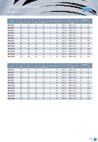
![164
Type
Motor In(A)
3~
400V
U.S.g.p.m. 0 17,6 22 26,4 31 35 40 44 53 66 79
Q
m³/h 0 4 5 6 7 8 9 10 12 15 18
kW HP l/min 0 66,7 83,3 100 117 133 150 167 200 250 300
S-151K/5* 3 4 7,6
H[m]
71 63 62 59 57 54 51 49 42 30 14
S-151K/7* 4 5,5 9,3 100 88 86 83 79 76 72 69 60 42,5 20
S-151K/8* 5,5 7,5 11 114 101 99 95 91 87 83 79 68 48,5 23
S-151K/9* 5,5 7,5 11,5 128 114 111 106 102 98 93 89 77 53 25
S-151K/10* 5,5 7,5 12,2 142 126 123 118 113 108 103 98 85 59,5 28
S-151K/11* 7,5 10 16,3 156 139 136 130 125 119 114 108 94 65,5 31
S-151K/12* 7,5 10 16,3 171 151 147 142 136 130 124 118 102 72 34
S-151K/13* 7,5 10 16,3 185 164 160 154 147 141 134 128 111 78,5 37
S-151K/16 9,2 12,5 19,9 228 202 197 189 181 173 165 157 136 95,5 45
S-151K/19 11 15 23,7 270 240 232 224 215 205 196 187 162 115 53
S-151K/22 13 17,5 27,7 317 281 271 260 249 238 227 214 187 134 62
S-151K/26 15 20 30,4 369 328 318 307 294 281 268 255 221 159 73
S-151K/29 18,5 25 38 412 366 353 342 328 313 299 284 247 176 81
S-151K/32 18,5 25 38 456 403 392 378 362 346 330 314 272 195 90
MODEL/FEATURES
6”SEMI-AXIAL SUBMERSIBLE PUMPS
Series S-151/S-152
USES:
They are suitable for lifting, pressure boosting and
distribution in civil and industrial installations, autoclave and
cistern inlets, washing plants, irrigation systems. Draws from
wells of min. diameter of 158mm, tanks or natural basins.
FEATURES:
- Shaft: Stainless steelAisi-431
- Impeller: Cast iron EN-GJL-250
(brass for K y X) or
FeG450 steel
- Diffuser: Cast iron EN-GJL-250
or FeG450 steel
- Suction support: Cast iron EN-GJL-250
or FeG450 steel
- pressure port
with non return valve: Cast iron EN-GJL-250
or FeG450 steel
- Passing of solids [mm]: 2
- Max. t° pumped liquid (ºC): 0-35º
- Max. working pressure (bar): 45
- Max. immersion depth [m]: 300
- Direction of rotation: Clockwise, looking
by the outlet
(counter clockwise
S-151-K)
- Q max. [m³/h]: 90
- H max. [m³/h]: 456
SPECIAL VERSIONS:
- XS: Version in stainless steel Aisi-316
- SB: Version in marine bronze (up tp máx. 25 bar)](https://image.slidesharecdn.com/saerallmodelcatalogcopy-220621133840-f3b41f50/85/SAER-Catalog-170-320.jpg)
![165
6”SEMI-AXIAL SUBMERSIBLE PUMPS
Series S-151/S-152
Type
Motor In(A)
3~
400V
U.S.g.p.m. 0 53 66 79 92 106 119 132 145 158 172
Q
m³/h 0 12 15 18 21 24 27 30 33 36 39
kW HP l/min 0 200 250 300 350 400 450 500 550 600 650
S-152 X/3* 3 4 7,6
H[m]
45 38 36 34 31 28 25 21 17 13 7,5
S-152 X/4* 4 5,5 9,3 60 51 48 45 42 37 33 28 23 17 10
S-152 X/5* 5,5 7,5 12,2 75 64 60 57 52 47 41 35 28 21 13
S-152 X/7* 7,5 10 16,3 105 90 84 79 73 65 58 49 39 29 18
S-152 X/8* 9,2 12,5 19,9 120 103 96 91 84 75 66 56 45 33 20
S-152 X/10* 11 15 23,7 150 128 120 113 104 93 82 69 56 41 25
S-152 X/12 13 17,5 27,7 180 154 144 136 125 112 99 83 68 50 30
S-152 X/14 15 20 30,4 210 180 168 159 146 131 115 97 79 58 35
S-152 X/17 18,5 25 38 255 218 204 192 177 158 140 118 96 70 43
S-152 X/20 22 30 43,7 300 256 240 226 208 186 164 138 112 82 50
S-152 X/22 26 35 53,3 330 282 264 249 229 205 181 152 124 91 55
S-152 X/24 26 35 53,3 360 308 288 272 250 224 197 166 135 99 60
S-152 X/26 30 40 60,2 390 333 312 294 271 242 214 180 146 107 65
Type
Motor In(A)
3~
400V
U.S.g.p.m. 0 53 66 79 92 106 119 132 145 158 185 211 238 264
Q
m³/h 0 12 15 18 21 24 27 30 33 36 42 48 54 60
kW HP l/min 0 200 250 300 350 400 450 500 550 600 700 800 900 1000
S-151A/2 * 4 5,5 9,4
H[m]
35 30 29 28 27 26 25 24 23 22 20 17 13 9
S-151A/3 * 5,5 7,5 12,2 52 48 47,5 46 45 43 42 41 39 37 33 28 23 17
S-151A/4 * 7,5 10 16,3 69 64 62 61 59 57 55 53 52 49 46 37 30 23
S-151A/5 * 9,2 12,5 19,9 86 80 79 77 75 72 70 67 65 62 55 47 38 29
S-151A/6 * 11 15 23,7 103 96 93 91 88 85 83 80 76 73 65 56 46 34
S-151A/7 * 13 17,5 27,7 122 111 109 104 102 98 95 91 89 85 78 65 55 40
S-151A/8 * 15 20 33 137 128 124 121 117 113 110 106 101 98 90 77 65 48
S-151A/9 * 18,5 25 38 155 142 137 134 129 126 122 119 115 112 104 87 71 54
S-151A/10 * 18,5 25 38 171 156 153 149 145 140 137 132 128 124 114 96 79 60
S-151A/11 22 30 43,7 187 172 168 164 159 155 151 146 141 137 127 106 87 66
S-151A/12 22 30 46 208 190 185 180 176 170 165 160 154 149 137 117 99 77
S-151A/13 26 35 53,3 224 206 200 195 190 184 178 173 167 159 150 127 107 83
S-151A/14 30 40 60,2 244 223 217 212 206 200 194 189 181 175 160 140 114 88
S-151A/15 30 40 60,2 257 235 230 223 218 212 205 199 192 185 173 150 122 94
S-151A/16 30 40 62 276 250 243 238 231 224 217 210 204 197 183 160 130 100
S-151A/17 37 50 73 293 266 258 251 245 238 232 226 218 211 196 170 138 107
S-151A/18 37 50 73 309 279 271 264 258 251 245 238 229 222 207 180 146 113
S-151A/19 37 50 75 326 295 286 278 272 265 258 252 244 236 219 190 154 119](https://image.slidesharecdn.com/saerallmodelcatalogcopy-220621133840-f3b41f50/85/SAER-Catalog-171-320.jpg)
![166
6”SEMI-AXIAL SUBMERSIBLE PUMPS
Series S-151/S-152
Type
Motor In(A)
3~
400V
U.S.g.p.m. 0 106 119 132 145 158 185 211 238 264 291 304 317
Q
m³/h 0 24 27 30 33 36 42 48 54 60 66 69 72
kW HP l/min 0 400 450 500 550 600 700 800 900 1000 1100 1150 1200
S-151B/2A * 4 5,5 9,4
H[m]
32 27 26 25,5 25 24 23 20 19 17 15 13 11
S-151B/2* 5,5 7,5 12,2 33 29 28,5 28 27 26 25 24 22 20 18 16 14
S-151B/3* 7,5 10 16,3 50 44 43 42 41 40 37 34 32 29 25 23 20
S-151B/4* 9,2 12,5 19,9 66 58 56 55 54 52 49 44 41 37 32 30 26
S-151B/5* 11 15 25 83 71 70 67 65 63 59 56 51 46 41 38 33
S-151B/6* 13 17,5 27,7 99 88 85 83 80 77 72 68 63 57 50 46 39
S-151B/7* 15 20 32 116 102 99 97 93 89 85 80 73 67 58 53 46
S-151B/8* 18,5 25 38 132 113 110 108 105 102 97 90 83 75 66 61 52
S-151B/9* 22 30 44,5 149 126 124 121 118 114 108 101 93 85 75 69 59
S-151B/10* 22 30 45,5 165 140 137 134 130 128 120 112 104 94 83 77 65
S-151B/11 26 35 53,3 182 158 152 149 144 140 132 124 114 103 91 84 72
S-151B/12 26 35 55 198 173 167 162 157 153 145 135 125 114 99 92 78
S-151B/13 30 40 60,2 215 186 180 176 170 165 156 146 135 123 107 99 85
S-151B/14 30 40 62 231 201 192 188 183 178 168 158 146 132 116 107 91
S-151B/15 37 50 73 248 215 207 202 196 191 180 169 156 141 124 114 98
S-151B/16 37 50 74,5 264 229 221 216 210 204 193 181 168 152 132 122 104
S-151B/17 37 50 76 281 242 236 230 222 217 204 193 179 162 141 130 111
Type
Motor In(A)
3~
400V
U.S.g.p.m. 0 238 264 291 304 317 330 343 370 396
Q
m³/h 0 54 60 66 69 72 75 78 84 90
kW HP l/min 0 900 1000 1100 1150 1200 1250 1300 1400 1500
S-151C/2* 5,5 7,5 13
H[m]
32 21 20 18 18 17 16 15 13 10
S-151C/3* 9,2 12,5 19,9 48 32 31 28 27 26 24 23 19 15
S-151C/4* 11 15 23,7 64 44 41 38 37 34 32 30 25 20
S-151C/5* 13 17,5 29 80 55 52 48 46 43 41 38 32 24
S-151C/6A* 15 20 30,4 95 64 60 56 54 50 47 43 36 27
S-151C/6* 18,5 25 38 96 66 62 58 55 52 49 45 38 30
S-151C/7* 18,5 25 40 112 77 72 66 63 60 57 53 44 35
S-151C/8* 22 30 45 128 87 82 75 72 68 64 60 50 39
S-151C/9* 26 35 53,3 144 99 92 85 81 77 72 68 56 44
S-151C/10* 26 35 55 160 110 102 95 90 85 80 75 62 49
S-151C/11 30 40 60,2 176 120 113 105 100 95 90 83 69 54
S-151C/12 37 50 73 192 132 124 114 109 104 98 91 75 59
S-151C/13 37 50 73 208 143 134 123 117 111 105 98 81 64
S-151C/14 37 50 76 224 153 145 133 126 120 113 105 87 69](https://image.slidesharecdn.com/saerallmodelcatalogcopy-220621133840-f3b41f50/85/SAER-Catalog-172-320.jpg)


![170
304 STAINLESS-STEEL SUBMERSIBLE PUMPS 6”
Series SIA-6
MODEL/FEATURES
Type kW HP Q [m3
/h] 0 3,5 5 6,5 8,5 10 12
SIA-6-6/10 3 4
H [m]
101 90 84 75 63 50 30
SIA-6-6/11 3 4 111 99 92 83 70 55 33
SIA-6-6/12 4 5,5 121 108 100 90 76 60 36
SIA-6-6/13 4 5,5 131 116 109 98 82 65 39
SIA-6-6/14 4 5,5 141 125 117 105 89 70 42
SIA-6-6/15 4 5,5 152 134 126 113 95 75 45
SIA-6-6/16 5,5 7,5 162 143 134 120 101 80 48
SIA-6-6/17 5,5 7,5 172 152 142 128 108 84 51
SIA-6-6/18 5,5 7,5 182 161 151 135 114 89 54
SIA-6-6/19 5,5 7,5 192 170 159 143 120 94 57
SIA-6-6/20 5,5 7,5 202 179 167 150 127 99 60
SIA-6-6/21 7,5 10 212 188 176 158 133 104 63
SIA-6-6/22 7,5 10 222 197 184 165 139 109 66
SIA-6-6/23 7,5 10 232 206 193 173 146 114 69
SIA-6-6/24 7,5 10 242 215 201 180 152 119 72
SIA-6-6/25 7,5 10 253 224 209 188 159 124 75
SIA-6-6/26 7,5 10 263 233 218 195 165 129 78
SIA-6-6/27 9,3 12,5 273 242 226 203 171 134 81
SIA-6-6/28 9,3 12,5 283 251 234 210 178 139 84
SIA-6-6/29 9,3 12,5 293 260 243 218 184 144 87
SIA-6-6/30 9,3 12,5 303 269 251 225 190 149 90
SIA-6-6/31 9,3 12,5 313 278 259 233 197 154 93
SIA-6-6/32 11 15 323 287 268 240 203 159 96
SIA-6-6/33 11 15 333 296 276 248 209 164 99
SIA-6-6/34 11 15 343 305 285 255 216 169 102
SIA-6-6/35 11 15 354 314 293 263 222 174 105
SIA-6-6/36 11 15 364 323 301 270 228 179 108
SIA-6-6/37 11 15 374 332 310 278 235 184 111
SIA-6-6/38 11 15 384 340 318 285 241 189 114
SIA-6-6/39 13 17,5 394 349 326 293 247 194 117
SIA-6-6/40 13 17,5 404 358 335 300 254 199 120
SIA-6-6/41 13 17,5 414 367 343 308 260 204 123
USES:
SIA 6” submersible pumps are made of corrosion-resistant
stainless steel AISI-304 in all the essential components of
the pump. The optimal design of the impellers and diffusers
makes it possible to obtain a better hydraulic efficiency. the
built-in check valve prevents return flow and reduces the risk
of water hammer.
Grate durability, good resistance to abrasives, easy assembly
and high resistance to axial thrust. Extremely durable water
lubricated bearings. All the assembly dimensions of the
pumps are in accordance with NEMA standards.
FEATURES:
-
- Shroud: StainlesssteelAisi-304.
-
- Impellers: StainlesssteelAisi-304.
-
- Diffuser: StainlesssteelAisi-304.
-
- Oultlet and suction support: StainlesssteelAisi-304.
-
- Max. flow [m³/h]: 78
-
- Max.head [m]: 565
-
- Max. t° pumped liquid [ºC]: 33
-
- Max. queantity of sand [g/m³]: 55
-
- Max. passing of solids [ppm]: 3000
-
- Rated speed: 2900 rpm](https://image.slidesharecdn.com/saerallmodelcatalogcopy-220621133840-f3b41f50/85/SAER-Catalog-176-320.jpg)
![171
304 STAINLESS-STEEL SUBMERSIBLE PUMPS 6”
Series SIA-6
Type kW HP Q [m3
/h] 0 5,5 7,5 9 11 13 16
SIA-6-9/8 3 4
H [m]
81 72 65 60 50 34 5
SIA-6-9/9 3 4 91 81 73 68 56 38 6
SIA-6-9/10 4 5,5 101 89 83 75 61 40 7
SIA-6-9/11 4 5,5 111 98 91 83 67 44 8
SIA-6-9/12 4 5,5 122 107 99 90 73 48 9
SIA-6-9/13 5,5 7,5 132 116 107 98 79 52 10
SIA-6-9/14 5,5 7,5 142 125 116 105 85 56 10
SIA-6-9/15 5,5 7,5 152 134 124 113 91 60 11
SIA-6-9/16 5,5 7,5 162 143 132 120 97 64 12
SIA-6-9/17 7,5 10 172 152 140 128 103 68 13
SIA-6-9/18 7,5 10 182 161 149 135 109 72 13
SIA-6-9/19 7,5 10 192 170 157 143 115 76 14
SIA-6-9/20 7,5 10 203 179 165 150 121 80 15
SIA-6-9/21 7,5 10 213 187 173 158 127 84 15
SIA-6-9/22 9,3 12,5 223 196 182 165 133 88 16
SIA-6-9/23 9,3 12,5 233 205 190 173 139 92 17
SIA-6-9/24 9,3 12,5 243 214 198 180 146 96 18
SIA-6-9/25 9,3 12,5 253 223 206 188 152 100 18
SIA-6-9/26 11 15 263 232 215 195 158 104 19
SIA-6-9/27 11 15 273 241 223 203 164 108 20
SIA-6-9/28 11 15 284 250 231 210 170 112 21
SIA-6-9/29 11 15 294 259 239 218 176 116 21
SIA-6-9/30 11 15 304 268 248 225 182 120 22
SIA-6-9/31 11 15 314 277 256 233 188 124 23
SIA-6-9/32 13 17,5 324 286 264 240 194 128 24
SIA-6-9/33 13 17,5 334 295 272 248 200 132 24
SIA-6-9/34 13 17,5 344 303 281 255 206 136 25
SIA-6-9/35 13 17,5 354 312 289 263 212 140 26
SIA-6-9/36 15 20 365 321 297 270 218 144 27
SIA-6-9/37 15 20 375 330 305 278 224 148 27
SIA-6-9/38 15 20 385 339 314 285 230 152 28
SIA-6-9/39 15 20 395 348 322 293 236 156 29
SIA-6-9/40 15 20 405 357 330 300 243 160 30](https://image.slidesharecdn.com/saerallmodelcatalogcopy-220621133840-f3b41f50/85/SAER-Catalog-177-320.jpg)
![172
304 STAINLESS-STEEL SUBMERSIBLE PUMPS 6”
Series SIA-6
Type kW HP Q [m3
/h] 0 7,5 10 12 14 16,5 18,5
SIA-6-12/06 3 4
H [m]
63 54 50 45 38 27 15
SIA-6-12/07 3 4 74 63 58 53 44 32 18
SIA-6-12/08 4 5,5 84 72 67 60 51 37 20
SIA-6-12/09 4 5,5 95 81 75 68 57 41 23
SIA-6-12/10 4 5,5 105 91 83 75 63 46 25
SIA-6-12/11 5,5 7,5 116 100 92 83 70 50 28
SIA-6-12/12 5,5 7,5 126 109 100 90 76 55 30
SIA-6-12/13 5,5 7,5 137 118 108 98 82 59 33
SIA-6-12/14 7,5 10 147 127 117 105 89 64 35
SIA-6-12/15 7,5 10 158 136 125 113 95 69 38
SIA-6-12/16 7,5 10 168 145 133 120 101 73 40
SIA-6-12/17 7,5 10 179 154 142 128 108 78 43
SIA-6-12/18 9,3 12,5 189 163 150 135 114 82 45
SIA-6-12/19 9,3 12,5 200 172 158 143 120 87 48
SIA-6-12/20 9,3 12,5 210 181 167 150 127 91 50
SIA-6-12/21 9,3 12,5 221 190 175 158 133 96 53
SIA-6-12/22 11 15 231 199 183 165 139 100 55
SIA-6-12/23 11 15 242 208 192 173 146 105 58
SIA-6-12/24 11 15 252 217 200 180 152 110 60
SIA-6-12/25 11 15 263 226 208 188 158 114 63
SIA-6-12/26 13 17,5 273 235 217 195 165 119 65
SIA-6-12/27 13 17,5 284 244 225 203 171 123 68
SIA-6-12/28 13 17,5 294 253 233 210 177 128 70
SIA-6-12/29 13 17,5 305 262 242 218 184 132 73
SIA-6-12/30 15 20 315 272 250 225 190 137 75
SIA-6-12/31 15 20 326 281 258 233 196 142 78
SIA-6-12/32 15 20 336 290 267 240 203 146 80
SIA-6-12/33 15 20 347 299 275 248 209 151 83
SIA-6-12/34 15 20 357 308 283 255 215 155 85
SIA-6-12/35 18,5 25 368 317 292 263 222 160 88
SIA-6-12/36 18,5 25 378 326 300 270 228 164 90
SIA-6-12/37 18,5 25 389 335 308 278 234 169 93
SIA-6-12/38 18,5 25 399 344 317 285 241 174 95
SIA-6-12/39 18,5 25 410 353 325 293 247 178 98
SIA-6-12/40 18,5 25 420 362 333 300 253 183 100
SIA-6-12/41 18,5 25 431 371 342 308 260 187 103](https://image.slidesharecdn.com/saerallmodelcatalogcopy-220621133840-f3b41f50/85/SAER-Catalog-178-320.jpg)
![173
304 STAINLESS-STEEL SUBMERSIBLE PUMPS 6”
Series SIA-6
Type kW HP Q [m3
/h] 0 11,5 14 17 20 23 26
SIA-6-17/05 3 4
H [m]
54 47 44 40 33 23 11
SIA-6-17/06 3 4 65 57 53 48 40 27 13
SIA-6-17/07 4 5,5 76 66 62 56 46 32 15
SIA-6-17/08 4 5,5 86 76 71 64 53 36 17
SIA-6-17/09 5,5 7,5 97 85 80 72 59 41 19
SIA-6-17/10 5,5 7,5 108 94 89 80 66 45 21
SIA-6-17/11 7,5 10 119 104 98 88 73 50 24
SIA-6-17/12 7,5 10 130 113 107 96 79 54 26
SIA-6-17/13 7,5 10 140 123 115 104 86 59 28
SIA-6-17/14 7,5 10 151 132 124 112 92 63 30
SIA-6-17/15 9,3 12,5 162 142 133 120 99 68 32
SIA-6-17/16 9,3 12,5 173 151 142 128 106 72 34
SIA-6-17/17 9,3 12,5 184 160 151 136 112 77 36
SIA-6-17/18 11 15 194 170 160 144 119 81 39
SIA-6-17/19 11 15 205 179 169 152 125 86 41
SIA-6-17/20 11 15 216 189 178 160 132 90 43
SIA-6-17/21 13 17,5 227 198 186 168 139 95 45
SIA-6-17/22 13 17,5 238 208 195 176 145 99 47
SIA-6-17/23 13 17,5 248 217 204 184 152 104 49
SIA-6-17/24 13 17,5 259 227 213 192 158 108 51
SIA-6-17/25 15 20 270 236 222 200 165 113 54
SIA-6-17/26 15 20 281 245 231 208 172 118 56
SIA-6-17/27 15 20 292 255 240 216 178 122 58
SIA-6-17/28 18,5 25 302 264 249 224 185 127 60
SIA-6-17/29 18,5 25 313 274 258 232 191 131 62
SIA-6-17/30 18,5 25 324 283 266 240 198 136 64
SIA-6-17/31 18,5 25 335 293 275 248 205 140 66
SIA-6-17/32 18,5 25 346 302 284 256 211 145 68
SIA-6-17/33 18,5 25 356 312 293 264 218 149 71
SIA-6-17/34 18,5 25 367 321 302 272 224 154 73
SIA-6-17/35 22 30 378 330 311 280 231 158 75
SIA-6-17/36 22 30 389 340 320 288 238 163 77
SIA-6-17/37 22 30 400 349 329 296 244 167 79
SIA-6-17/38 22 30 410 359 337 304 251 172 81
SIA-6-17/39 22 30 421 368 346 312 257 176 83
SIA-6-17/40 22 30 432 378 355 320 264 181 86
SIA-6-17/41 26 35 443 387 364 328 271 185 88
SIA-6-17/42 26 35 454 396 373 336 277 190 90
SIA-6-17/43 26 35 464 406 382 344 284 194 92](https://image.slidesharecdn.com/saerallmodelcatalogcopy-220621133840-f3b41f50/85/SAER-Catalog-179-320.jpg)
![174
304 STAINLESS-STEEL SUBMERSIBLE PUMPS 6”
Series SIA-6
Type kW HP Q [m3
/h] 0 12 17,5 20,5 23,5 26,5 29
SIA-6-20/04 3 4
H [m]
43 40 36 32 27 21 14
SIA-6-20/05 4 5,5 54 50 45 40 34 26 18
SIA-6-20/06 4 5,5 65 60 54 48 41 32 21
SIA-6-20/07 5,5 7,5 75 71 63 56 47 37 25
SIA-6-20/08 5,5 7,5 86 81 72 64 54 42 28
SIA-6-20/09 7,5 10 97 91 81 72 61 47 32
SIA-6-20/10 7,5 10 108 101 90 80 68 53 35
SIA-6-20/11 9,3 12,5 118 111 99 88 74 58 39
SIA-6-20/12 9,3 12,5 129 121 108 96 81 63 42
SIA-6-20/13 9,3 12,5 140 131 117 104 88 68 46
SIA-6-20/14 11 15 151 141 126 112 95 74 49
SIA-6-20/15 11 15 161 151 135 120 101 79 53
SIA-6-20/16 13 17,5 172 161 144 128 108 84 56
SIA-6-20/17 13 17,5 183 171 153 136 115 89 60
SIA-6-20/18 13 17,5 194 181 162 144 122 95 63
SIA-6-20/19 15 20 204 191 171 152 128 100 67
SIA-6-20/20 15 20 215 202 180 160 135 105 70
SIA-6-20/21 18,5 25 226 212 189 168 142 110 74
SIA-6-20/22 18,5 25 237 222 198 176 149 116 77
SIA-6-20/23 18,5 25 247 232 207 184 155 121 81
SIA-6-20/24 18,5 25 258 242 216 192 162 126 84
SIA-6-20/25 18,5 25 269 252 225 200 169 131 88
SIA-6-20/26 22 30 280 262 234 208 176 137 91
SIA-6-20/27 22 30 290 272 243 216 182 142 95
SIA-6-20/28 22 30 301 282 252 224 189 147 98
SIA-6-20/29 22 30 312 292 261 232 196 152 102
SIA-6-20/30 22 30 323 302 270 240 203 158 105
SIA-6-20/31 26 35 333 312 279 248 209 163 109
SIA-6-20/32 26 35 344 322 288 256 216 168 112
SIA-6-20/33 26 35 355 332 297 264 223 173 116
SIA-6-20/34 26 35 366 343 306 272 230 179 119
SIA-6-20/35 26 35 376 353 315 280 236 184 123
SIA-6-20/36 30 40 387 363 324 288 243 189 126
SIA-6-20/37 30 40 398 373 333 296 250 194 130
SIA-6-20/38 30 40 409 383 342 304 257 200 133
SIA-6-20/39 30 40 419 393 351 312 263 205 137
SIA-6-20/40 30 40 430 403 360 320 270 210 140
SIA-6-20/41 37 50 441 413 369 328 277 215 144
SIA-6-20/42 37 50 452 423 378 336 284 221 147
SIA-6-20/43 37 50 462 433 387 344 290 226 151
SIA-6-20/44 37 50 473 443 396 352 297 231 154](https://image.slidesharecdn.com/saerallmodelcatalogcopy-220621133840-f3b41f50/85/SAER-Catalog-180-320.jpg)
![175
304 STAINLESS-STEEL SUBMERSIBLE PUMPS 6”
Series SIA-6
Type kW HP Q [m3
/h] 0 18,5 20 24 28 30,5 35
SIA-6-24/03 3 4
H [m]
30 27 26 24 21 17 9
SIA-6-24/04 4 5,5 40 36 35 32 27 23 12
SIA-6-24/05 4 5,5 50 44 43 40 34 28 15
SIA-6-24/06 5,5 7,5 60 53 52 48 41 34 18
SIA-6-24/07 7,5 10 70 62 61 56 48 40 21
SIA-6-24/08 7,5 10 80 71 69 64 55 45 24
SIA-6-24/09 9,3 12,5 90 80 78 72 62 51 27
SIA-6-24/10 9,3 12,5 100 89 87 80 68 57 30
SIA-6-24/11 11 15 110 98 95 88 75 62 33
SIA-6-24/12 11 15 120 107 104 96 82 68 36
SIA-6-24/13 11 15 130 115 113 104 89 74 39
SIA-6-24/14 13 17,5 140 124 121 112 96 79 42
SIA-6-24/15 13 17,5 150 133 130 120 103 85 45
SIA-6-24/16 15 20 160 142 139 128 109 91 48
SIA-6-24/17 15 20 170 151 147 136 116 96 51
SIA-6-24/18 18,5 25 180 160 156 144 123 102 54
SIA-6-24/19 18,5 25 190 169 165 152 130 108 57
SIA-6-24/20 18,5 25 200 178 173 160 137 113 60
SIA-6-24/21 18,5 25 210 186 182 168 144 119 63
SIA-6-24/22 22 30 220 195 191 176 150 125 66
SIA-6-24/23 22 30 230 204 199 184 157 130 69
SIA-6-24/24 22 30 240 213 208 192 164 136 72
SIA-6-24/25 22 30 250 222 217 200 171 142 75
SIA-6-24/26 26 35 260 231 225 208 178 147 78
SIA-6-24/27 26 35 270 240 234 216 185 153 81
SIA-6-24/28 26 35 280 249 243 224 191 159 84
SIA-6-24/29 26 35 290 258 251 232 198 164 87
SIA-6-24/30 30 40 300 266 260 240 205 170 89
SIA-6-24/31 30 40 310 275 269 248 212 176 92
SIA-6-24/32 30 40 320 284 277 256 219 181 95
SIA-6-24/33 30 40 330 293 286 264 226 187 98
SIA-6-24/34 30 40 340 302 295 272 232 193 101
SIA-6-24/35 37 50 350 311 303 280 239 198 104
SIA-6-24/36 37 50 360 320 312 288 246 204 107
SIA-6-24/37 37 50 370 329 321 296 253 210 110
SIA-6-24/38 37 50 380 337 329 304 260 215 113
SIA-6-24/39 37 50 390 346 338 312 267 221 116
SIA-6-24/40 37 50 400 355 347 320 273 227 119
SIA-6-24/41 37 50 410 364 355 328 280 232 122
SIA-6-24/42 37 50 420 373 364 336 287 238 125](https://image.slidesharecdn.com/saerallmodelcatalogcopy-220621133840-f3b41f50/85/SAER-Catalog-181-320.jpg)
![176
304 STAINLESS-STEEL SUBMERSIBLE PUMPS 6”
Series SIA-6
Type kW HP Q [m3
/h] 0 8 16 24 28 32 39
SIA-6-30/01 1,1 1,5
H [m]
12 11 10 8 7 6 3
SIA-6-30/02 2,2 3 23 23 20 17 16 13 8
SIA-6-30/03 3 4 35 34 30 26 24 20 12
SIA-6-30/04 4 5,5 46 45 40 35 32 27 16
SIA-6-30/05 5,5 7,5 58 56 51 45 41 35 22
SIA-6-30/06 5,5 7,5 69 67 60 53 48 41 26
SIA-6-30/07 7,5 10 81 78 71 62 57 49 31
SIA-6-30/08 7,5 10 91 89 81 71 64 55 35
SIA-6-30/09 9,3 12,5 103 101 91 80 73 63 40
SIA-6-30/10 9,3 12,5 114 111 100 88 80 69 43
SIA-6-30/11 9,3 12,5 125 122 110 96 87 75 46
SIA-6-30/12 11 15 137 133 120 106 96 83 52
SIA-6-30/13 11 15 148 144 130 114 103 89 55
SIA-6-30/14 13 17,5 160 156 141 125 113 98 61
SIA-6-30/15 13 17,5 171 167 150 133 121 103 64
SIA-6-30/16 15 20 183 179 162 143 130 113 71
SIA-6-30/17 15 20 194 189 171 150 136 118 74
SIA-6-30/18 18,5 25 207 203 184 163 148 129 82
SIA-6-30/19 18,5 25 218 214 194 170 155 135 85
SIA-6-30/20 18,5 25 229 224 203 179 163 141 90
SIA-6-30/21 18,5 25 241 236 214 187 170 147 92
SIA-6-30/22 22 30 252 246 223 197 180 157 99
SIA-6-30/23 22 30 264 257 233 206 187 162 103
SIA-6-30/24 22 30 275 268 242 214 194 168 106
SIA-6-30/25 22 30 285 278 250 222 202 174 109
SIA-6-30/26 22 30 296 289 260 229 208 179 112
SIA-6-30/27 26 35 310 302 274 243 221 190 120
SIA-6-30/28 26 35 320 313 283 250 228 197 123
SIA-6-30/29 26 35 331 323 293 258 235 204 127
SIA-6-30/30 26 35 343 334 301 267 242 209 130
SIA-6-30/31 26 35 353 344 310 274 249 214 134
SIA-6-30/32 30 40 367 358 324 287 261 225 143
SIA-6-30/33 30 40 378 369 337 294 269 231 147
SIA-6-30/34 30 40 389 379 343 304 276 238 149
SIA-6-30/35 30 40 400 390 352 310 283 244 153
SIA-6-30/39 37 50 445 435 395 350 320 278 175
SIA-6-30/43 37 50 489 478 432 383 350 301 189
SIA-6-30/46 45 60 532 520 475 424 390 340 220
SIA-6-30/49 45 60 565 554 504 450 413 360 232](https://image.slidesharecdn.com/saerallmodelcatalogcopy-220621133840-f3b41f50/85/SAER-Catalog-182-320.jpg)
![177
304 STAINLESS-STEEL SUBMERSIBLE PUMPS 6”
Series SIA-6
Type kW HP Q [m3
/h] 0 10 20 30 40 50 60
SIA-6-46/01-B 1,1 1,5
H [m]
10 9 8 7 6 4 -
SIA-6-46/01 2,2 3 14 13 12 10 9 7 4
SIA-6-46/02-BB 2,2 3 19 18 17 15 12 8 2
SIA-6-46/02 3 4 27 25 24 21 18 14 8
SIA-6-46/03-C 4 5,5 36 34 32 28 24 18 9
SIA-6-46/03 5,5 7,5 41 40 36 32 28 23 15
SIA-6-46/04-C 5,5 7,5 49 47 44 39 34 26 15
SIA-6-46/04 7,5 10 54 52 48 44 38 31 20
SIA-6-46/05 7,5 10 67 64 60 54 47 38 24
SIA-6-46/06 9,3 12,5 81 77 72 65 56 45 30
SIA-6-46/07 11 15 94 90 84 76 66 53 35
SIA-6-46/08-C 11 15 103 98 91 82 71 56 35
SIA-6-46/08 13 17,5 108 104 96 88 76 62 41
SIA-6-46/09-C 13 17,5 117 112 104 94 82 65 41
SIA-6-46/09 15 20 122 117 109 99 87 70 47
SIA-6-46/10 15 20 135 129 120 109 95 76 51
SIA-6-46/11 18,5 25 149 143 133 122 107 86 58
SIA-6-46/12 18,5 25 162 155 144 132 116 94 63
SIA-6-46/13 22 30 176 168 157 143 126 102 69
SIA-6-46/14 22 30 189 181 168 153 134 108 73
SIA-6-46/15 22 30 202 193 180 163 142 115 77
SIA-6-46/16 26 35 217 208 193 177 155 125 84
SIA-6-46/17 26 35 229 220 205 187 163 131 89
SIA-6-46/18 30 40 245 235 219 199 175 141 97
SIA-6-46/19 30 40 258 246 230 209 183 148 101
SIA-6-46/20 30 40 271 259 241 219 192 155 105
SIA-6-46/21 37 50 285 274 255 233 205 167 115
SIA-6-46/22 37 50 298 286 267 244 215 174 120
SIA-6-46/23 37 50 311 298 278 254 223 180 124
SIA-6-46/24 37 50 323 310 289 264 232 188 128
SIA-6-46/26 45 60 358 343 321 294 260 213 148
SIA-6-46/28 45 60 383 368 345 316 280 228 159
SIA-6-46/30 45 60 410 393 368 337 298 243 168
SIA-6-46/33 55 75 452 435 407 373 330 270 188
SIA-6-46/35 55 75 479 460 430 395 350 285 199
SIA-6-46/37 66 90 508 488 457 420 372 305 213](https://image.slidesharecdn.com/saerallmodelcatalogcopy-220621133840-f3b41f50/85/SAER-Catalog-183-320.jpg)
![178
304 STAINLESS-STEEL SUBMERSIBLE PUMPS 6”
Series SIA-6
Type kW HP Q [m3
/h] 0 20 30 40 50 60 78
SIA-6-60/01-A 1,5 2
H [m]
11 10 8 7 6 1 -
SIA-6-60/01 2,2 3 14 13 11 9 8 4 1
SIA-6-60/02-B 3 4 22 21 18 16 13 6 1
SIA-6-60/02 4 5,5 28 26 23 19 17 10 6
SIA-6-60/03 5,5 7,5 42 39 35 30 26 16 10
SIA-6-60/04 7,5 10 56 53 47 41 35 22 14
SIA-6-60/05 9,3 12,5 71 65 59 51 44 28 18
SIA-6-60/06 11 15 85 79 71 62 54 34 22
SIA-6-60/07 13 17,5 99 92 83 73 63 40 26
SIA-6-60/08-B 13 17,5 108 100 90 80 68 42 26
SIA-6-60/08 15 20 114 106 95 84 73 46 31
SIA-6-60/09-B 15 20 122 113 102 90 78 48 31
SIA-6-60/09 18,5 25 129 121 109 96 83 54 37
SIA-6-60/10 18,5 25 143 133 120 106 92 60 41
SIA-6-60/11 22 30 158 147 133 117 102 67 45
SIA-6-60/12 22 30 172 159 143 126 110 72 50
SIA-6-60/13 26 35 187 174 157 138 120 78 55
SIA-6-60/14 26 35 200 186 168 148 129 85 58
SIA-6-60/15 26 35 214 197 178 157 137 89 60
SIA-6-60/16 30 40 230 213 192 168 147 95 65
SIA-6-60/17 30 40 243 225 203 178 156 100 68
SIA-6-60/18 37 50 260 242 220 193 168 111 78
SIA-6-60/19 37 50 273 255 230 203 177 117 82
SIA-6-60/20 37 50 287 267 242 213 184 122 85
SIA-6-60/21 37 50 301 280 253 223 192 128 89
SIA-6-60/22 45 60 323 302 274 242 211 141 100](https://image.slidesharecdn.com/saerallmodelcatalogcopy-220621133840-f3b41f50/85/SAER-Catalog-184-320.jpg)
![179
304 STAINLESS-STEEL SUBMERSIBLE PUMPS 6”
Series SIA-6
DIMENSIONS AND WEIGHTS
Type
P2
L1 [mm]
ØE
[mm]
G
Motor
Weight Kg
kW HP [Inches]
SIA-6-6/10 3 4 723 142 2 1/2" 4" 29
SIA-6-6/11 3 4 768 142 2 1/2" 4" 30
SIA-6-6/12 4 5,5 813 142 2 1/2" 4" 34
SIA-6-6/13 4 5,5 858 142 2 1/2" 4" 36
SIA-6-6/14 4 5,5 903 142 2 1/2" 4" 40
SIA-6-6/15 4 5,5 948 142 2 1/2" 4" 41
SIA-6-6/16 5,5 7,5 993 142 2 1/2" 4" 45
SIA-6-6/17 5,5 7,5 1038 142 2 1/2" 4" 46
SIA-6-6/18 5,5 7,5 1083 142 2 1/2" 4" 47
SIA-6-6/19 5,5 7,5 1128 142 2 1/2" 4" 49
SIA-6-6/20 5,5 7,5 1173 142 2 1/2" 4" 52
SIA-6-6/21 7,5 10 1218 142 2 1/2" 6" 53,5
SIA-6-6/22 7,5 10 1263 142 2 1/2" 6" 55
SIA-6-6/23 7,5 10 1308 142 2 1/2" 6" 58
SIA-6-6/24 7,5 10 1353 142 2 1/2" 6" 61
SIA-6-6/25 7,5 10 1398 142 2 1/2" 6" 63
SIA-6-6/26 7,5 10 1443 142 2 1/2" 6" 64,5
SIA-6-6/27 9,3 12,5 1488 142 2 1/2" 6" 66
SIA-6-6/28 9,3 12,5 1533 142 2 1/2" 6" 68
SIA-6-6/29 9,3 12,5 1578 142 2 1/2" 6" 71
SIA-6-6/30 9,3 12,5 1623 142 2 1/2" 6" 74
SIA-6-6/31 9,3 12,5 1668 142 2 1/2" 6" 76
SIA-6-6/32 11 15 1713 142 2 1/2" 6" 78
SIA-6-6/33 11 15 1758 142 2 1/2" 6" 80
SIA-6-6/34 11 15 1803 142 2 1/2" 6" 82
SIA-6-6/35 11 15 1848 142 2 1/2" 6" 83,5
SIA-6-6/36 11 15 1893 142 2 1/2" 6" 85
SIA-6-6/37 11 15 1938 142 2 1/2" 6" 86,5
SIA-6-6/38 11 15 1983 142 2 1/2" 6" 88
SIA-6-6/39 13 17,5 2028 142 2 1/2" 6" 90,5
SIA-6-6/40 13 17,5 2073 142 2 1/2" 6" 93
SIA-6-6/41 13 17,5 2118 142 2 1/2" 6" 95](https://image.slidesharecdn.com/saerallmodelcatalogcopy-220621133840-f3b41f50/85/SAER-Catalog-185-320.jpg)
![180
304 STAINLESS-STEEL SUBMERSIBLE PUMPS 6”
Series SIA-6
Type
P2
L1 [mm]
ØE
[mm]
G
Motor
Weight Kg
kW HP [Inches]
SIA-6-9/8 3 4 633 142 2 1/2" 4" 26
SIA-6-9/9 3 4 678 142 2 1/2" 4" 27
SIA-6-9/10 4 5,5 723 142 2 1/2" 4" 29
SIA-6-9/11 4 5,5 768 142 2 1/2" 4" 30
SIA-6-9/12 4 5,5 813 142 2 1/2" 4" 34
SIA-6-9/13 5,5 7,5 858 142 2 1/2" 4" 36
SIA-6-9/14 5,5 7,5 903 142 2 1/2" 4" 40
SIA-6-9/15 5,5 7,5 948 142 2 1/2" 4" 41
SIA-6-9/16 5,5 7,5 993 142 2 1/2" 4" 45
SIA-6-9/17 7,5 10 1038 142 2 1/2" 6" 46
SIA-6-9/18 7,5 10 1083 142 2 1/2" 6" 47
SIA-6-9/19 7,5 10 1128 142 2 1/2" 6" 49
SIA-6-9/20 7,5 10 1173 142 2 1/2" 6" 52
SIA-6-9/21 7,5 10 1218 142 2 1/2" 6" 53,5
SIA-6-9/22 9,3 12,5 1263 142 2 1/2" 6" 55
SIA-6-9/23 9,3 12,5 1308 142 2 1/2" 6" 58
SIA-6-9/24 9,3 12,5 1353 142 2 1/2" 6" 61
SIA-6-9/25 9,3 12,5 1398 142 2 1/2" 6" 63
SIA-6-9/26 11 15 1443 142 2 1/2" 6" 64,5
SIA-6-9/27 11 15 1488 142 2 1/2" 6" 66
SIA-6-9/28 11 15 1533 142 2 1/2" 6" 68
SIA-6-9/29 11 15 1578 142 2 1/2" 6" 71
SIA-6-9/30 11 15 1623 142 2 1/2" 6" 74
SIA-6-9/31 11 15 1668 142 2 1/2" 6" 76
SIA-6-9/32 13 17,5 1713 142 2 1/2" 6" 78
SIA-6-9/33 13 17,5 1758 142 2 1/2" 6" 80
SIA-6-9/34 13 17,5 1803 142 2 1/2" 6" 82
SIA-6-9/35 13 17,5 1848 142 2 1/2" 6" 83,5
SIA-6-9/36 15 20 1893 142 2 1/2" 6" 85
SIA-6-9/37 15 20 1938 142 2 1/2" 6" 86,5
SIA-6-9/38 15 20 1983 142 2 1/2" 6" 88
SIA-6-9/39 15 20 2028 142 2 1/2" 6" 90,5
SIA-6-9/40 15 20 2073 142 2 1/2" 6" 93](https://image.slidesharecdn.com/saerallmodelcatalogcopy-220621133840-f3b41f50/85/SAER-Catalog-186-320.jpg)
![181
304 STAINLESS-STEEL SUBMERSIBLE PUMPS 6”
Series SIA-6
Type
P2
L1 [mm]
ØE
[mm]
G
Motor
Weight Kg
kW HP [Inches]
SIA-6-12/06 3 4 543 142 2 1/2" 4" 21
SIA-6-12/07 3 4 588 142 2 1/2" 4" 22
SIA-6-12/08 4 5,5 633 142 2 1/2" 4" 26
SIA-6-12/09 4 5,5 678 142 2 1/2" 4" 27
SIA-6-12/10 4 5,5 723 142 2 1/2" 4" 29
SIA-6-12/11 5,5 7,5 768 142 2 1/2" 4" 30
SIA-6-12/12 5,5 7,5 813 142 2 1/2" 4" 34
SIA-6-12/13 5,5 7,5 858 142 2 1/2" 4" 36
SIA-6-12/14 7,5 10 903 142 2 1/2" 6" 40
SIA-6-12/15 7,5 10 948 142 2 1/2" 6" 41
SIA-6-12/16 7,5 10 993 142 2 1/2" 6" 45
SIA-6-12/17 7,5 10 1038 142 2 1/2" 6" 46
SIA-6-12/18 9,3 12,5 1083 142 2 1/2" 6" 47
SIA-6-12/19 9,3 12,5 1128 142 2 1/2" 6" 49
SIA-6-12/20 9,3 12,5 1173 142 2 1/2" 6" 52
SIA-6-12/21 9,3 12,5 1218 142 2 1/2" 6" 53,5
SIA-6-12/22 11 15 1263 142 2 1/2" 6" 55
SIA-6-12/23 11 15 1308 142 2 1/2" 6" 58
SIA-6-12/24 11 15 1353 142 2 1/2" 6" 61
SIA-6-12/25 11 15 1398 142 2 1/2" 6" 63
SIA-6-12/26 13 17,5 1443 142 2 1/2" 6" 64,5
SIA-6-12/27 13 17,5 1488 142 2 1/2" 6" 66
SIA-6-12/28 13 17,5 1533 142 2 1/2" 6" 68
SIA-6-12/29 13 17,5 1578 142 2 1/2" 6" 71
SIA-6-12/30 15 20 1623 142 2 1/2" 6" 74
SIA-6-12/31 15 20 1668 142 2 1/2" 6" 76
SIA-6-12/32 15 20 1713 142 2 1/2" 6" 78
SIA-6-12/33 15 20 1758 142 2 1/2" 6" 80
SIA-6-12/34 15 20 1803 142 2 1/2" 6" 82
SIA-6-12/35 18,5 25 1848 142 2 1/2" 6" 83,5
SIA-6-12/36 18,5 25 1893 142 2 1/2" 6" 85
SIA-6-12/37 18,5 25 1938 142 2 1/2" 6" 86,5
SIA-6-12/38 18,5 25 1983 142 2 1/2" 6" 88
SIA-6-12/39 18,5 25 2028 142 2 1/2" 6" 90,5
SIA-6-12/40 18,5 25 2073 142 2 1/2" 6" 93
SIA-6-12/41 18,5 25 2118 142 2 1/2" 6" 95](https://image.slidesharecdn.com/saerallmodelcatalogcopy-220621133840-f3b41f50/85/SAER-Catalog-187-320.jpg)
![182
304 STAINLESS-STEEL SUBMERSIBLE PUMPS 6”
Series SIA-6
Type
P2
L1 [mm]
ØE
[mm]
G
Motor
Weight Kg
kW HP [Inches]
SIA-6-17/05 3 4 548 142 2 1/2" 4" 12,5
SIA-6-17/06 3 4 603 142 2 1/2" 4" 14
SIA-6-17/07 4 5,5 658 142 2 1/2" 4" 15,5
SIA-6-17/08 4 5,5 713 142 2 1/2" 4" 18
SIA-6-17/09 5,5 7,5 768 142 2 1/2" 4" 19,5
SIA-6-17/10 5,5 7,5 823 142 2 1/2" 4" 21
SIA-6-17/11 7,5 10 878 142 2 1/2" 6" 23
SIA-6-17/12 7,5 10 933 142 2 1/2" 6" 25
SIA-6-17/13 7,5 10 988 142 2 1/2" 6" 28
SIA-6-17/14 7,5 10 1043 142 2 1/2" 6" 29
SIA-6-17/15 9,3 12,5 1098 142 2 1/2" 6" 30,5
SIA-6-17/16 9,3 12,5 1122 142 2 1/2" 6" 32
SIA-6-17/17 9,3 12,5 1140 142 2 1/2" 6" 34,5
SIA-6-17/18 11 15 1263 142 2 1/2" 6" 36
SIA-6-17/19 11 15 1318 142 2 1/2" 6" 37,5
SIA-6-17/20 11 15 1373 142 2 1/2" 6" 40
SIA-6-17/21 13 17,5 1428 142 2 1/2" 6" 41,5
SIA-6-17/22 13 17,5 1483 142 2 1/2" 6" 43
SIA-6-17/23 13 17,5 1538 142 2 1/2" 6" 45
SIA-6-17/24 13 17,5 1593 142 2 1/2" 6" 47
SIA-6-17/25 15 20 1648 142 2 1/2" 6" 48,5
SIA-6-17/26 15 20 1703 142 2 1/2" 6" 50
SIA-6-17/27 15 20 1758 142 2 1/2" 6" 52
SIA-6-17/28 18,5 25 1813 142 2 1/2" 6" 54
SIA-6-17/29 18,5 25 1868 142 2 1/2" 6" 55,5
SIA-6-17/30 18,5 25 1923 142 2 1/2" 6" 57,5
SIA-6-17/31 18,5 25 1978 142 2 1/2" 6" 59,5
SIA-6-17/32 18,5 25 2033 142 2 1/2" 6" 62
SIA-6-17/33 18,5 25 2088 142 2 1/2" 6" 63,5
SIA-6-17/34 18,5 25 2143 142 2 1/2" 6" 65
SIA-6-17/35 22 30 2198 142 2 1/2" 6" 67
SIA-6-17/36 22 30 2253 142 2 1/2" 6" 69
SIA-6-17/37 22 30 2308 142 2 1/2" 6" 71,5
SIA-6-17/38 22 30 2363 142 2 1/2" 6" 73
SIA-6-17/39 22 30 2418 142 2 1/2" 6" 74,5
SIA-6-17/40 22 30 2473 142 2 1/2" 6" 76
SIA-6-17/41 26 35 2528 142 2 1/2" 6" 77,5
SIA-6-17/42 26 35 2583 142 2 1/2" 6" 79
SIA-6-17/43 26 35 2638 142 2 1/2" 6" 81](https://image.slidesharecdn.com/saerallmodelcatalogcopy-220621133840-f3b41f50/85/SAER-Catalog-188-320.jpg)
![183
304 STAINLESS-STEEL SUBMERSIBLE PUMPS 6”
Series SIA-6
Type
P2
L1 [mm]
ØE
[mm]
G
Motor
Weight Kg
kW HP [Inches]
SIA-6-20/04 3 4 440 142 2 1/2" 4" 11
SIA-6-20/05 4 5,5 548 142 2 1/2" 4" 12,5
SIA-6-20/06 4 5,5 603 142 2 1/2" 4" 14
SIA-6-20/07 5,5 7,5 658 142 2 1/2" 4" 15,5
SIA-6-20/08 5,5 7,5 713 142 2 1/2" 4" 18
SIA-6-20/09 7,5 10 768 142 2 1/2" 6" 19,5
SIA-6-20/10 7,5 10 823 142 2 1/2" 6" 21
SIA-6-20/11 9,3 12,5 878 142 2 1/2" 6" 23
SIA-6-20/12 9,3 12,5 933 142 2 1/2" 6" 25
SIA-6-20/13 9,3 12,5 988 142 2 1/2" 6" 28
SIA-6-20/14 11 15 1043 142 2 1/2" 6" 29
SIA-6-20/15 11 15 1098 142 2 1/2" 6" 30,5
SIA-6-20/16 13 17,5 1122 142 2 1/2" 6" 32
SIA-6-20/17 13 17,5 1140 142 2 1/2" 6" 34,5
SIA-6-20/18 13 17,5 1263 142 2 1/2" 6" 36
SIA-6-20/19 15 20 1318 142 2 1/2" 6" 37,5
SIA-6-20/20 15 20 1373 142 2 1/2" 6" 40
SIA-6-20/21 18,5 25 1428 142 2 1/2" 6" 41,5
SIA-6-20/22 18,5 25 1483 142 2 1/2" 6" 43
SIA-6-20/23 18,5 25 1538 142 2 1/2" 6" 45
SIA-6-20/24 18,5 25 1593 142 2 1/2" 6" 47
SIA-6-20/25 18,5 25 1648 142 2 1/2" 6" 48,5
SIA-6-20/26 22 30 1703 142 2 1/2" 6" 50
SIA-6-20/27 22 30 1758 142 2 1/2" 6" 52
SIA-6-20/28 22 30 1813 142 2 1/2" 6" 54
SIA-6-20/29 22 30 1868 142 2 1/2" 6" 55,5
SIA-6-20/30 22 30 1923 142 2 1/2" 6" 57,5
SIA-6-20/31 26 35 1978 142 2 1/2" 6" 59,5
SIA-6-20/32 26 35 2033 142 2 1/2" 6" 62
SIA-6-20/33 26 35 2088 142 2 1/2" 6" 63,5
SIA-6-20/34 26 35 2143 142 2 1/2" 6" 65
SIA-6-20/35 26 35 2198 142 2 1/2" 6" 67
SIA-6-20/36 30 40 2253 142 2 1/2" 6" 69
SIA-6-20/37 30 40 2308 142 2 1/2" 6" 71,5
SIA-6-20/38 30 40 2363 142 2 1/2" 6" 73
SIA-6-20/39 30 40 2418 142 2 1/2" 6" 74,5
SIA-6-20/40 30 40 2473 142 2 1/2" 6" 76
SIA-6-20/41 37 50 2528 142 2 1/2" 6" 77,5
SIA-6-20/42 37 50 2583 142 2 1/2" 6" 79
SIA-6-20/43 37 50 2638 142 2 1/2" 6" 81
SIA-6-20/44 37 50 2693 142 2 1/2" 6" 83](https://image.slidesharecdn.com/saerallmodelcatalogcopy-220621133840-f3b41f50/85/SAER-Catalog-189-320.jpg)
![184
304 STAINLESS-STEEL SUBMERSIBLE PUMPS 6”
Series SIA-6
Type
P2
L1 [mm]
ØE
[mm]
G
Motor
Weight Kg
kW HP [Inches]
SIA-6-24/03 3 4 330 142 2 1/2" 4" 9,5
SIA-6-24/04 4 5,5 440 142 2 1/2" 4" 11
SIA-6-24/05 4 5,5 548 142 2 1/2" 4" 12,5
SIA-6-24/06 5,5 7,5 603 142 2 1/2" 4" 14
SIA-6-24/07 7,5 10 658 142 2 1/2" 4" 15,5
SIA-6-24/08 7,5 10 713 142 2 1/2" 6" 18
SIA-6-24/09 9,3 12,5 768 142 2 1/2" 6" 19,5
SIA-6-24/10 9,3 12,5 823 142 2 1/2" 6" 21
SIA-6-24/11 11 15 878 142 2 1/2" 6" 23
SIA-6-24/12 11 15 933 142 2 1/2" 6" 25
SIA-6-24/13 11 15 988 142 2 1/2" 6" 28
SIA-6-24/14 13 17,5 1043 142 2 1/2" 6" 29
SIA-6-24/15 13 17,5 1098 142 2 1/2" 6" 30,5
SIA-6-24/16 15 20 1122 142 2 1/2" 6" 32
SIA-6-24/17 15 20 1140 142 2 1/2" 6" 34,5
SIA-6-24/18 18,5 25 1263 142 2 1/2" 6" 36
SIA-6-24/19 18,5 25 1318 142 2 1/2" 6" 37,5
SIA-6-24/20 18,5 25 1373 142 2 1/2" 6" 40
SIA-6-24/21 18,5 25 1428 142 2 1/2" 6" 41,5
SIA-6-24/22 22 30 1483 142 2 1/2" 6" 43
SIA-6-24/23 22 30 1538 142 2 1/2" 6" 45
SIA-6-24/24 22 30 1593 142 2 1/2" 6" 47
SIA-6-24/25 22 30 1648 142 2 1/2" 6" 48,5
SIA-6-24/26 26 35 1703 142 2 1/2" 6" 50
SIA-6-24/27 26 35 1758 142 2 1/2" 6" 52
SIA-6-24/28 26 35 1813 142 2 1/2" 6" 54
SIA-6-24/29 26 35 1868 142 2 1/2" 6" 55,5
SIA-6-24/30 30 40 1923 142 2 1/2" 6" 57,5
SIA-6-24/31 30 40 1978 142 2 1/2" 6" 59,5
SIA-6-24/32 30 40 2033 142 2 1/2" 6" 62
SIA-6-24/33 30 40 2088 142 2 1/2" 6" 63,5
SIA-6-24/34 30 40 2143 142 2 1/2" 6" 65
SIA-6-24/35 37 50 2198 142 2 1/2" 6" 67
SIA-6-24/36 37 50 2253 142 2 1/2" 6" 69
SIA-6-24/37 37 50 2308 142 2 1/2" 6" 71,5
SIA-6-24/38 37 50 2363 142 2 1/2" 6" 73
SIA-6-24/39 37 50 2418 142 2 1/2" 6" 74,5
SIA-6-24/40 37 50 2473 142 2 1/2" 6" 76
SIA-6-24/41 37 50 2528 142 2 1/2" 6" 77,5
SIA-6-24/42 37 50 2583 142 2 1/2" 6" 79](https://image.slidesharecdn.com/saerallmodelcatalogcopy-220621133840-f3b41f50/85/SAER-Catalog-190-320.jpg)
![185
304 STAINLESS-STEEL SUBMERSIBLE PUMPS 6”
Series SIA-6
Type
P2
L1 [mm]
ØE
[mm]
G
Motor
Weight Kg
kW HP [Inches]
SIA-6-30/01 1,1 1,5 349 131 3" 4" 4
SIA-6-30/02 2,2 3 445 131 3" 4" 5,8
SIA-6-30/03 3 4 541 131 3" 4" 9,5
SIA-6-30/04 4 5,5 637 131 3" 4" 12
SIA-6-30/05 5,5 7,5 749 131 3" 4" 16
SIA-6-30/06 5,5 7,5 845 131 3" 4" 18,5
SIA-6-30/07 7,5 10 941 142 3" 4” 19,5
SIA-6-30/08 7,5 10 1037 142 3" 4” 22
SIA-6-30/09 9,3 12,5 1133 142 3" 6" 24
SIA-6-30/10 9,3 12,5 1129 142 3" 6" 26,5
SIA-6-30/11 9,3 12,5 1325 142 3" 6" 28
SIA-6-30/12 11 15 1421 142 3" 6" 30,5
SIA-6-30/13 11 15 1517 142 3" 6" 33
SIA-6-30/14 13 17,5 1613 142 3" 6" 34,5
SIA-6-30/15 13 17,5 1709 142 3" 6" 37
SIA-6-30/16 15 20 1805 142 3" 6" 39,5
SIA-6-30/17 15 20 1901 142 3" 6" 41
SIA-6-30/18 18,5 25 1997 142 3" 6" 44
SIA-6-30/19 18,5 25 2093 142 3" 6" 45,5
SIA-6-30/20 18,5 25 2189 142 3" 6" 48
SIA-6-30/21 18,5 25 2285 142 3" 6" 50,5
SIA-6-30/22 22 30 2381 142 3" 6" 52
SIA-6-30/23 22 30 2477 142 3" 6" 54,5
SIA-6-30/24 22 30 2573 142 3" 6" 57
SIA-6-30/25 22 30 2669 142 3" 6" 58,5
SIA-6-30/26 22 30 2765 142 3" 6" 61
SIA-6-30/27 26 35 2861 142 3" 6" 63
SIA-6-30/28 26 35 2957 142 3" 6" 65,5
SIA-6-30/29 26 35 3053 142 3" 6" 68
SIA-6-30/30 26 35 3149 142 3" 6" 69,5
SIA-6-30/31 26 35 3245 142 3" 6" 72
SIA-6-30/32 30 40 3341 142 3" 6" 74,5
SIA-6-30/33 30 40 3137 142 3" 6" 76
SIA-6-30/34 30 40 3533 142 3" 6" 78,5
SIA-6-30/35 30 40 3629 142 3" 6" 81
SIA-6-30/39 37 50 4260 142 3" 6" 116,5
SIA-6-30/43 37 50 4644 142 3" 6" 129,5
SIA-6-30/46 45 60 4881 142 3" 6" 171
SIA-6-30/49 45 60 5769 142 3" 6" 179,5](https://image.slidesharecdn.com/saerallmodelcatalogcopy-220621133840-f3b41f50/85/SAER-Catalog-191-320.jpg)
![186
304 STAINLESS-STEEL SUBMERSIBLE PUMPS 6”
Series SIA-6
Type
P2
L1 [mm]
ØE
[mm]
G
Motor
Weight Kg
kW HP [Inches]
SIA-6-46/01-B 1,1 1,5 364 145 3" 4" 6,5
SIA-6-46/01 2,2 3 364 145 3" 4" 6,5
SIA-6-46/02-BB 2,2 3 477 145 3" 4" 9
SIA-6-46/02 3 4 477 145 3" 4" 9
SIA-6-46/03-C 4 5,5 590 145 3" 4" 12,5
SIA-6-46/03 5,5 7,5 590 145 3" 4" 12,5
SIA-6-46/04-C 5,5 7,5 703 145 3" 4" 16
SIA-6-46/04 7,5 10 719 148 3" 4” 17
SIA-6-46/05 7,5 10 832 148 3" 4” 19,5
SIA-6-46/06 9,3 12,5 945 148 3" 6" 23
SIA-6-46/07 11 15 1058 148 3" 6" 26,5
SIA-6-46/08-C 11 15 1171 148 3" 6" 29
SIA-6-46/08 13 17,5 1171 148 3" 6" 29
SIA-6-46/09-C 13 17,5 1284 148 3" 6" 32,5
SIA-6-46/09 15 20 1284 148 3" 6" 32,5
SIA-6-46/10 15 20 1397 148 3" 6" 36
SIA-6-46/11 18,5 25 1510 148 3" 6" 39,5
SIA-6-46/12 18,5 25 1623 148 3" 6" 43
SIA-6-46/13 22 30 1736 148 3" 6" 46,5
SIA-6-46/14 22 30 1849 148 3" 6" 49
SIA-6-46/15 22 30 1902 148 3" 6" 52,5
SIA-6-46/16 26 35 2075 148 3" 6" 53
SIA-6-46/17 26 35 2188 148 3" 6" 57,5
SIA-6-46/18 30 40 2301 148 3" 6" 60
SIA-6-46/19 30 40 2414 148 3" 6" 63,5
SIA-6-46/20 30 40 2607 148 3" 6" 67
SIA-6-46/21 37 50 2720 148 3" 6" 70,5
SIA-6-46/22 37 50 2833 148 3" 6" 74
SIA-6-46/23 37 50 2946 148 3" 6" 78,5
SIA-6-46/24 37 50 3059 148 3" 6" 82
SIA-6-46/26 45 60 3403 190 3" 8" 114
SIA-6-46/28 45 60 3629 190 3" 8" 121
SIA-6-46/30 45 60 3855 190 3" 8" 128
SIA-6-46/33 55 75 4194 190 4" 8" 138,5
SIA-6-46/35 55 75 4420 190 3" 8" 149
SIA-6-46/37 66 90 4646 190 4" 8" 160](https://image.slidesharecdn.com/saerallmodelcatalogcopy-220621133840-f3b41f50/85/SAER-Catalog-192-320.jpg)
![187
304 STAINLESS-STEEL SUBMERSIBLE PUMPS 6”
Series SIA-6
Type
P2
L1 [mm]
ØE
[mm]
G
Motor
Weight Kg
kW HP [Inches]
SIA-6-60/01-A 1,5 2 364 146 3" 4" 8,5
SIA-6-60/01 2,2 3 364 146 3" 4" 8,5
SIA-6-60/02-B 3 4 477 146 3" 4" 11
SIA-6-60/02 4 5,5 477 146 3" 4" 11
SIA-6-60/03 5,5 7,5 590 146 3" 4" 13
SIA-6-60/04 7,5 10 719 148 3" 6" 15
SIA-6-60/05 9,3 12,5 832 148 3" 6" 20
SIA-6-60/06 11 15 950 148 3" 6" 22,5
SIA-6-60/07 13 17,5 1058 148 3" 6" 26
SIA-6-60/08-B 13 17,5 1171 148 3" 6" 28,5
SIA-6-60/08 15 20 1171 148 3" 6" 28,5
SIA-6-60/09-B 15 20 1284 148 3" 6" 32
SIA-6-60/09 18,5 25 1284 148 3" 6" 32
SIA-6-60/10 18,5 25 1397 148 3" 6" 35
SIA-6-60/11 22 30 1510 148 3" 6" 32,5
SIA-6-60/12 22 30 1623 148 3" 6" 36
SIA-6-60/13 26 35 1736 148 3" 6" 39,5
SIA-6-60/14 26 35 1849 148 3" 6" 43
SIA-6-60/15 26 35 1962 148 3" 6" 46,5
SIA-6-60/16 30 40 2075 148 3" 6" 49
SIA-6-60/17 30 40 2188 148 3" 6" 52,5
SIA-6-60/18 37 50 2381 148 3" 6" 53
SIA-6-60/19 37 50 2494 148 3" 6" 57,5
SIA-6-60/20 37 50 2607 148 3" 6" 60
SIA-6-60/21 37 50 2722 148 3" 6" 63,5
SIA-6-60/22 45 60 2782 190 4 8" 67](https://image.slidesharecdn.com/saerallmodelcatalogcopy-220621133840-f3b41f50/85/SAER-Catalog-193-320.jpg)
![188
Type
Motor In(A)
3~
400V
U.S.g.p.m. 0 53 70 97 110 123 141 158
Q
m³/h 0 12 16 22 25 28 32 36
kW HP l/min 0 200 267 367 417 467 533 600
NR-201 X/2* 4 5,5 9,4
H[m]
49,5 45,5 44 42 38 35 29 24
NR-201 X/3* 5,5 7,5 12,2 75 69 66 63 58 52 45 36
NR-201 X/4* 7,5 10 16,3 100 92 88 84 78 70 60 48
NR-201 X/5* 9,2 12,5 19,9 125 115 110 105 98 87 75 60
NR-201 X/6* 11 15 23,8 150 138 132 125 117 104 90 72
NR-201 X/7* 13 17,5 27,7 175 161 154 146 137 122 105 84
NR-201 X/8* 15 20 30,4 200 184 176 167 156 139 120 96
NR-201 X/10* 18,5 25 38 250 230 220 209 195 174 150 120
NR-201 X/12* 22 30 43,7 300 276 264 250 234 208 180 144
NR-201 X/14* 26 35 53,3 350 322 308 292 273 243 210 168
NR-201 X/16 30 40 60,2 400 368 352 334 312 278 240 192
NR-201 X/18 37 50 73 450 414 396 376 351 313 270 216
NR-201 X/20 37 50 73 500 460 440 418 390 348 300 240
NR-201 X/22 45 60 89 550 506 484 460 429 383 330 264
NR-201 X/24 45 60 94 600 552 528 500 468 416 360 288
NR-201 X/26 52 70 105 650 598 572 543 507 452 390 312
NR-201 X/28 60 80 118 700 644 616 584 546 486 420 336
NR-201 X/30 60 80 118 750 690 660 627 585 522 450 360
NR-201 X/32 67 90 131 800 736 704 668 624 556 480 384
NR-201 X/34 67 90 135 850 782 748 710 663 591 510 408
MODEL/FEATURES
RADIAL SUBMERSIBLE PUMPS 8”
Series NR-201
USES:
They are suitable for lifting, pressure boosting and
distribution in civil and industrial installations, autoclave and
cistern inlets, washing plants, irrigation systems. Draws from
wells of min. diameter of 204mm, tanks or natural basins.
FEATURES:
- Shaft: Stainless steelAisi-431
- Impeller: Brass
- Diffuser: Cast iron EN-GJL-250
- Suction support: Cast iron EN-GJL-250
- pressure port: Cast iron
ENGJS-500/7
- External shell: FeG450 epoxy
coated carbonsteel
- Valve: StainlesssteelAisi-304
Cast iron EN-GJL-250
- Passing of solids [mm]: 5
- Max. t° pumped liquid (ºC): 0-30º
- Max. working pressure (bar): 85
- Max. immersion depth [m]: 300
- Direction of rotation : Clockwise, looking
by the outlet
- Q max. [m³/h]: 120
- H max. [m³/h]: 850
- XNR-201: Version stainless steel-316 on request.
NR-201 XNR-201](https://image.slidesharecdn.com/saerallmodelcatalogcopy-220621133840-f3b41f50/85/SAER-Catalog-194-320.jpg)
![189
Type
Motor In(A)
3~
400V
U.S.g.p.m. 0 70 97 110 123 141 158 176 198
Q
m³/h 0 16 22 25 28 32 36 40 45
kW HP l/min 0 269 367 417 467 533 600 667 750
NR-201A/2* 5,5 7,5 12,2
H[m]
53 48 45 43 41 37 33 28 21
NR-201A/3* 7,5 10 16,3 79 72 68 64 62 56 49 42 31
NR-201A/4* 9,2 12,5 19,9 105 97 90 86 82 74 65 55 41
NR-201A/5* 13 17,5 27,7 132 120 113 107 103 93 81 69 51
NR-201A/6* 15 20 30,4 158 145 136 129 124 111 98 83 62
NR-201A/7* 18,5 25 38 184 169 158 150 144 130 114 97 72
NR-201A/8* 22 30 43,7 211 193 181 171 165 148 130 111 82
NR-201A/9* 22 30 43,7 237 217 203 193 185 167 146 125 92
NR-201A/10* 26 35 53,3 263 241 226 214 206 185 162 138 103
NR-201A/11* 26 35 53,3 290 265 248 236 226 204 179 152 113
NR-201A/12* 30 40 60,2 316 289 271 257 247 222 195 166 123
NR-201A/14* 37 50 73 366 334 315 303 288 264 231 197 144
NR-201A/16 45 60 89 421 385 361 343 329 296 260 221 164
NR-201A/18 45 60 93 474 433 406 386 370 333 293 249 185
NR-201A/20 52 70 105 527 482 452 428 412 370 325 277 205
NR-201A/22 60 80 110 571 524 493 472 447 407 353 295 223
NR-201A/24 60 80 118 632 578 542 514 494 444 390 329 236
NR-201A/26 67 90 131 686 629 595 572 541 498 438 367 267
Type
Motor In(A)
3~
400V
U.S.g.p.m. 0 158 176 198 220 247 277 308 352 396
Q
m³/h 0 36 40 45 50 56 63 70 80 90
kW HP l/min 0 600 667 750 833 933 1050 1167 1333 1500
NR-201B/2* 9,2 12,5 19,9
H[m]
51 46 45 44 42 40 37 33 28 21
NR-201B/3* 15 20 30,4 77 69 68 66 63 60 56 50 42 31
NR-201B/4* 18,5 25 38 102 92 90 88 84 80 74 66 56 41
NR201-B/5* 26 35 53,3 128 115 113 110 105 100 93 83 70 52
NR-201B/6* 30 40 60,2 153 138 135 132 126 120 111 99 82 59
NR-201B/7* 37 50 73 179 161 158 154 147 140 130 116 98 65
NR-201B/8* 37 50 75 204 184 180 176 168 160 148 132 112 74
NR-201B/9* 45 60 89 245 216 213 204 199 189 174 153 124 89
NR-201B/10* 52 70 105 272 240 237 233 224 213 194 174 140 102
NR-201B/12* 60 80 118 326 288 284 279 269 255 232 211 163 122
NR-201B/14 67 90 135 380 336 338 326 314 299 274 241 194 144
NR-201B/16 75 100 157 436 390 386 380 369 350 319 282 232 169
NR-201B/18 92 125 179 481 439 434 427 415 387 355 312 254 188
NR-201B/19 92 125 181 518 463 458 451 435 411 377 338 274 207
NR-201B/20 92 125 184 546 488 482 474 461 438 406
RADIAL SUBMERSIBLE PUMPS 8”
Series NR-201](https://image.slidesharecdn.com/saerallmodelcatalogcopy-220621133840-f3b41f50/85/SAER-Catalog-195-320.jpg)
![190
Type
Motor In(A)
3~400V
U.S.g.p.m. 0 220 247 277 308 352 396 422 476 502 528
Q
m³/h 0 50 56 63 70 80 90 96 108 114 120
kW HP l/min 0 833 933 1050 1167 ## 1500 ## 1800 1900 2000
NR-201C/2A* 11 15 23,7
H[m]
50 39 37 35 33 30 24 21 15 10
NR-201C/2* 13 17,5 27,7 58 48 47 45 42 38 33 30 22 20 15
NR-201C/3A* 15 20 30,4 75 59 56 53 50 45 36 32 23
NR-201C/3* 18,5 25 38 87 72 71 67 63 57 50 45 33 29 23
NR-201C/4* 22 30 43,7 116 96 94 89 84 76 66 60 44 39 30
NR-201C/5* 30 40 60,2 145 120 118 111 105 95 83 75 55 49 38
NR-201C/6* 37 50 73 174 144 141 133 126 114 99 90 66 58 45
NR-201C/7* 45 60 89 203 168 165 156 147 133 116 105 82 68 53
NR-201C/8* 52 70 102 232 192 188 178 168 152 132 120 93 78 60
NR-201C/9* 55 75 110 261 216 212 200 189 171 149 135 105 88 68
NR-201C/10* 60 80 118 290 240 235 222 210 190 165 150 115 97 75
NR-201C/11 67 90 131 319 264 259 245 231 209 182 165 121 107 83
NR-201C/12 75 100 152 348 288 282 266 252 228 198 180 132 116 90
NR-201C/13 83 113 166 377 312 306 289 273 247 215 195 151 127 98
NR-201C/14 92 125 179 406 336 329 311 294 266 231 210 159 136 105
NR-201C/15 92 125 185 435 360 353 333 315 285 248 225 173 146 113
Tipo
T
(mm)
H
(mm)
L
(mm)
Ø
Max (mm)
Ø D“G Ø d (mm)
L + H Kg
L NEMA H T
NR-201 X/2 1165 644 521 190 3” 144 6”MS 152 NEMA 1.18.413 45,5 85,5
NR-201 X/3 1260 708 552 190 3” 144 6”MS 152 NEMA 1.18.413 51 95
NR-201 X/4 1367 772 595 190 3” 144 6”MS 152 NEMA 1.18.413 56 105
NR-201 X/5 1471 836 635 190 3” 144 6”MS 152 NEMA 1.18.413 61 115
NR-201 X/6 1585 900 685 190 3” 144 6”MS 152 NEMA 1.18.413 66 126
NR-201 X/7 1689 964 725 190 3” 144 6”MS 152 NEMA 1.18.413 71,5 133,5
NR-201 X/8 1803 1028 775 190 3” 144 6”MS 152 NEMA 1.18.413 76,5 182
NR-201 X/10 2131 1256 875 190 3” 144 6”MS 152 NEMA 1.18.413 87 206
NR-201 X/12 2349 1384 965 190 3” 144 6”MS 152 NEMA 1.18.413 97 229
NR-201 X/14 2567 1512 1055 190 3” 144 6”MS 152 NEMA 1.18.413 108 277
NR-201 X/16 2803 1668 1135 190 3” 144 6”MS 152 NEMA 1.18.413 118 309
NR-201 X/18 3121 1896 1225 190 3” 144 6”MS 153 NEMA 1.18.413 128 319
NR-201 X/20 3249 2024 1225 190 3” 144 6”MS 153 NEMA 1.18.413 139 351
NR-201 X/22 3147 2152 995 198 3” 192 8”MS 201 NEMA 1.18.424 149 383
NR-201 X/24 3275 2280 995 198 3” 192 8”MS 201 NEMA 1.18.424 159 393
NR-201 X/26 3473 2408 1065 198 3” 192 8”MS 201 NEMA 1.18.424 170 425
NR-201 X/28 3415 2280 1135 198 3” 192 8”MS 201 NEMA 1.18.424 180 457
NR-201 X/30 3899 2764 1135 198 3” 192 8”MS 201 NEMA 1.18.424 190 467
NR-201 X/32 4127 2892 1235 198 3” 192 8”MS 201 NEMA 1.18.424 200 499
NR-201 X/34 4255 3020 1235 198 3” 192 8”MS 201 NEMA 1.18.424 210 509
RADIAL SUBMERSIBLE PUMPS 8”
Series NR-201
DIMENSIONS AND WEIGHTS](https://image.slidesharecdn.com/saerallmodelcatalogcopy-220621133840-f3b41f50/85/SAER-Catalog-196-320.jpg)

![192
SEMI-AXIAL SUBMERSIBLE PUMPS 8”
Series S-181
USES:
They are suitable for lifting, pressure boosting and
distribution in civil and industrial installations, autoclave and
cistern inlets, washing plants, irrigation systems. Draws from
wells of min. diameter of 210mm, tanks or natural basins.
FEATURES:
- Shaft: Stainless steelAisi-431
- Impeller: Cast iron EN-GJL-250
or steel FeG450
- Diffuser: Cast iron EN-GJL-250
or steel FeG450
- Suction support: Cast iron EN-GJL-250
or steel FeG450
- Pressure port
with non retur valve: Cast iron EN-GJL-250
or steel FeG450
- Passing of solids [mm]: 3
- Max. t° pumped liquid (ºC): 0-30º
- Max. working pressure (bar): 36
- Max. immersion depth [m]: 300
- Direction of rotation: Clockwise, looking
by the outlet.
- Q max. [m³/h]: 228
- H max. [m³/h]: 360
SPECIAL VERSIONS:
- XS: Version in stainless steel Aisi-316
- SB: Version in marine bronze (máx. 25 bar)
Type
Motor In(A)
3~
400V
U.S.g.p.m. 0 106 132 158 185 211 264 317 370 440
Q
m³/h 0 24 30 36 42 48 60 72 84 100
kW HP l/min 0 400 500 600 700 800 1000 1200 1400 1667
S-181A/1* 5,5 7,5 12,3
H[m]
27 24 23 22 22 21,5 19 17 14 10
S-181A/2A* 7,5 10 16,3 47 41 38 37,5 36 34 29 27 19 15
S-181A/2* 9,2 12,5 19,9 54 48 47 46 43 41 37 32 24 19
S-181A/3A* 11 15 23,8 71 62 57 54 51 48 44 38 30 21
S-181A/3* 13 17,5 27,7 81 72 69 66 63 60 52 45 36 29
S-181A/4A* 15 20 30,4 94 82 77 73 69 65 58 51 39 30
S-181A/4* 18,5 25 38 108 96 93 89 86 82 74 66 53 39
S-181A/5* 22 30 43,7 135 120 115 111 108 103 93 83 70 49
S-181A/6* 26 35 53,3 162 144 139 133 129 124 116 104 85 58
S-181A/7* 30 40 62 189 173 167 162 160 153 144 129 106 68
S-181A/8* 37 50 73 216 192 189 182 177 172 161 141 121 78
S-181A/9* 45 60 89 243 217 210 205 198 192 175 156 134 88
S-181A/10* 45 60 89 270 240 232 224 217 210 193 170 148 97
S-181A/11 55 75 111 297 264 256 248 238 231 212 184 163 107
S-181A/12 59 80 118 324 289 278 270 260 252 232 204 177 117
S-181A/13 67 90 131 351 312 302 292 282 273 251 225 192 127
MODEL/FEATURES](https://image.slidesharecdn.com/saerallmodelcatalogcopy-220621133840-f3b41f50/85/SAER-Catalog-198-320.jpg)
![193
SEMI-AXIAL ELECTRIC SUBMERSIBLE PUMPS 8”
Series S-181
Type
Motor In(A)
3~
400V
U.S.g.p.m. 0 211 264 317 370 440 476 502 528 555 594 638
Q
m³/h 0 48 60 72 84 100 108 114 120 126 135 145
kW HP l/min 0 800 1000 1200 1400 1667 1800 1900 2000 2100 2250 2417
S-181B/1* 7,5 10 16,3
H[m]
28 25 24,5 24 23 20,5 20 18 17 15 13 8
S-181B/2B* 9,2 12,5 19,9 45 37 35 33 29 25,5 25 21 21
S-181B/2A* 11 15 23,8 50 42 40 38 36 32 30 27 25 22 17 7
S-181B/2* 13 17,5 27,7 57 49 47 45 43 39,5 39 36 34 30 25 18
S-181B/3B* 15 20 30,4 67 56 52 51 48
S-181B/3A* 18,5 25 38 71 61 58 54 51 44,5 42 38 36 33 26 18
S-181B/3* 22 30 43,7 85 74 72 69 65 59 56 53 50 46 38 28
S-181B/4* 26 35 53,3 114 98 94 90 84 76,5 70 66 62 56 48 36
S-181B/5A* 30 40 60,2 123 105 101 96 88
S-181B/5* 37 50 73 142 123 118 113 109 98,5 93 87 81 73 60
S-181B/6* 45 60 89 162 146 140 133 127 115 107 101 95 87 72 55
S-181B/7* 52 70 101 189 170 163 155 148 135 127 120 112 102 87 67
S-181B/8* 59 80 118 216 194 186 177 169 153 145 137 127 118 102 80
S-181B/9* 67 90 131 243 223 213 205 194 180 169 159 150 139 123 101
S-181B/10* 67 90 138 277 246 237 227 218 199 188 178 166 154 138 113
S-181B/11 83 113 166 305 271 260 249 240 220 207 196 183 170 148 118
S-181B/12 92 125 177 332 295 284 272 259 237 223 211 199 184 163 123
S-181B/13 92 125 185 360 320 307 294 283 258 244 232 218 205 180 133
Type
Motor In(A)
3~
400V
U.S.g.p.m. 0 422 476 502 528 555 581 634 705
Q
m³/h 0 96 108 114 120 126 132 144 160
kW HP l/min 0 1600 1800 1900 2000 2100 2200 2400 2667
S-181C/1* 7,5 10 18
H[m]
27 18 17 16 16 15 15 14 11
S-181C/2B* 11 15 25 44 32 28 26 25 23 21 17
S-181C/2* 15 20 30,4 55 39 37 36 33 32 30 27 22
S-181C/3A* 18,5 25 38 76 52 48 46 44 42 39 33 25
S-181C/3* 22 30 45 82 58 54 52 50 48 45 39 33
S-181C/4A* 26 35 53,3 97 69 62 60 58 54 53 45 34
S-181C/4* 30 40 60,2 109 79 73 71 67 64 60 52 44
S-181C/5* 37 50 75 139 99 95 91 87 84 80 71 60
S-181C/6* 45 60 95 164 118 112 109 106 103 98 87 72
S-181C/7* 55 75 106 189 137 131 127 122 118 112 99 84
S-181C/8* 59 80 118 216 157 151 145 141 134 128 110 88
S-181C/9* 67 90 134 243 177 170 165 159 151 144 124 99
S-181C/10 75 100 152 270 196 188 183 177 168 160 138 110
S-181C/11 92 125 177 297 216 208 201 194 184 176 151 121
S-181C/12 92 125 180 324 236 227 219 212 203 192 166 132](https://image.slidesharecdn.com/saerallmodelcatalogcopy-220621133840-f3b41f50/85/SAER-Catalog-199-320.jpg)
![194
SEMI-AXIAL ELECTRIC SUBMERSIBLE PUMPS 8”
Series S-181
Type
Motor In(A)
3~
400V
U.S.g.p.m. 0 476 502 528 555 581 634 705 740 793 845 898 951 1004
Q
m³/h 0 108 114 120 126 132 144 160 168 180 192 204 216 228
kW HP l/min 0 1800 1900 2000 2100 2200 2400 2667 2800 3000 3200 3400 3600 3800
S-181D/1* 9,2 12,5 21
H[m]
28 22 21 20,5 20 19 18 17 16 14 12 10 7 5
S-181D/2A* 15 20 30,4 47 33 32 31 30 29 27 24 22 19 16 13
S-181D/2* 18,5 25 39,5 56 43 42 41 40 39 37 33 31 28 24 20 17 12
S-181D/3A* 22 30 43,7 71 51 49 48 46 45 42 37 34 30
S-181D/3* 30 40 60,2 86 65 63 62 60 59 55 50 47 43 38 32 26 18
S-181D/4* 37 50 73 115 87 85 83 81 79 74 67 63 57 49 42 34 26
S-181D/5* 52 70 103 140 106 103 101 98 95 92 81 78 70 61 52 41 30
S-181D/6* 59 80 118 168 128 125 122 119 116 109 99 93 84 75 63 51 36
S-181D/7* 67 90 134 196 152 147 144 140 136 128 115 109 99 85 73 60 42
S-181D/8 75 100 154 224 171 168 165 161 158 149 136 129 114 100 85 68 53
S-181D/9 92 125 177 252 194 189 185 182 178 169 156 146 131 116 100 82 64
Type
T
(mm)
H
(mm)
L
(mm)
Ø
Max (mm)
Ø D“G Ø d (mm)
L + H Kg
L NEMA H T
S-181A/1 1162 610 552 202 5” 144 6”MS 152 NEMA 1.18.413 36,5 80,5
S-181A/2A 1205 750 595 202 5” 144 6”MS 152 NEMA 1.18.413 49 98
S-181A/2 1385 750 635 202 5” 144 6”MS 152 NEMA 1.18.413 49 103
S-181A/3A 1575 890 685 202 5” 144 6”MS 152 NEMA 1.18.413 61,5 121,5
S-181A/3 1615 890 725 202 5” 144 6”MS 152 NEMA 1.18.413 61,5 123,5
S-181A/4A 1805 1030 775 202 5” 144 6”MS 152 NEMA 1.18.413 74 139
S-181A/4 1905 1030 875 202 5” 144 6”MS 152 NEMA 1.18.413 74 155
S-181A/5 2135 1170 965 202 5” 144 6”MS 152 NEMA 1.18.413 86,5 177,5
S-181A/6 2365 1310 1055 202 5” 144 6”MS 152 NEMA 1.18.413 99 202
S-181A/7 2585 1450 1135 202 5” 144 6”MS 152 NEMA 1.18.413 111,5 220,5
S-181A/8 2815 1590 1225 202 5” 144 6”MS 153 NEMA 1.18.413 124 254
S-181A/9 2725 1730 995 202 5” 192 8”MS 201 NEMA 1.18.424 136,5 295,5
S-181A/10 2865 1870 995 202 5” 192 8”MS 201 NEMA 1.18.424 149 308
S-181A/11 3075 2010 1065 202 5” 192 8”MS 201 NEMA 1.18.424 161,5 333,5
S-181A/12 3285 2150 1135 202 5” 192 8”MS 201 NEMA 1.18.424 174 362
S-181A/13 3525 2290 1235 202 5” 192 8”MS 201 NEMA 1.18.424 186,5 394,5
DIMENSIONS AND WEIGHTS](https://image.slidesharecdn.com/saerallmodelcatalogcopy-220621133840-f3b41f50/85/SAER-Catalog-200-320.jpg)

![196
Type [kW] [HP] Q [m3
/h] 0 20 40 60 80 100
SIA-8-77/01 5,5 7,5
H [m]
22 20 17 14 12 7
SIA-8-77/02-B 5,5 7,5 33 31 27 22 17 7
SIA-8-77/02 7,5 10 41 39 33 28 23 14
SIA-8-77/03-B 9,3 12,5 53 51 44 37 28 15
SIA-8-77/03 11 15 61 58 50 42 34 20
SIA-8-77/04-B 13 17,5 73 70 61 52 40 21
SIA-8-77/04 15 20 81 78 68 57 46 27
SIA-8-77/05 18,5 25 101 97 85 72 58 34
SIA-8-77/06 22 30 120 116 102 86 69 41
SIA-8-77/07 26 35 140 136 119 101 81 48
SIA-8-77/08-B 26 35 152 147 129 108 84 48
SIA-8-77/08 30 40 160 156 137 116 93 55
SIA-8-77/09 30 40 179 174 152 128 103 62
SIA-8-77/10 37 50 200 194 171 145 117 68
SIA-8-77/11 37 50 218 213 186 158 127 75
SIA-8-77/12 45 60 242 237 209 178 145 88
SIA-8-77/13 55 75 264 259 228 195 158 98
SIA-8-77/14 55 75 283 278 245 209 170 104
SIA-8-77/15 55 75 302 297 261 222 181 110
SIA-8-77/16 66 90 324 318 280 239 194 120
SIA-8-77/17 66 90 343 337 298 253 207 125
SIA-8-77/18 66 90 363 355 313 267 217 132
SIA-8-77/19 75 100 383 375 332 282 230 140
SIA-8-77/20 75 100 403 395 349 297 240 146
MODEL/FEATURES
304 STAINLESS-STEEL SUBMERSIBLE PUMPS 8”
Series SIA-8
USES:
SIA 8” submersible pumps are made of corrosion-resistant
stainless steel AISI-304 in all the essential components of
the pump. The optimal design of the impellers and diffusers
makes it possible to obtain a better hydraulic efficiency. the
built-in check valve prevents return flow and reduces the risk
of water hammer.
Good resistance to abrasives, easy assembly and high
resistance to axial thrust. Extremely durable water lubricated
bearings.All the assembly dimensions of the pumps are in
accordance with NEMA standards.
FEATURES:
-
- Shroud: StainlessstellAisi-304.
-
- Impeller: StainlessstellAisi-304.
-
- Diffuser: StainlessstellAisi-304.
-
- Oultlet and suction support: StainlessstellAisi-304.
-
- Max. flow. [m³/h]: 124
-
- Max. head [m]: 423
-
- Max. t° pumped liquid [ºC]: 33
-
- Max. quantity of sand [g/m³]: 55
-
- Max. passing of solids [ppm]: 3000
-
- Rated speed: 2900 rpm](https://image.slidesharecdn.com/saerallmodelcatalogcopy-220621133840-f3b41f50/85/SAER-Catalog-202-320.jpg)
![197
Type [kW] [HP] Q [m3
/h] 0 20 40 70 80 124
SIA-8-95/01 5,5 7,5
H [m]
23 21 18 14 13 6
SIA-8-95/02-BB 5,5 7,5 27 26 23 19 14 ‐
SIA-8-95/02-A 8 10 39 36 32 26 22 8
SIA-8-95/02 9,3 12,5 44 41 36 29 25 11
SIA-8-95/03-BB 9,3 12,5 49 46 40 32 25 7
SIA-8-95/03-B 11 15 56 53 47 38 31 11
SIA-8-95/03 13,0 17,5 65 62 55 44 38 18
SIA-8-95/04-B 15 20 77 74 65 53 44 18
SIA-8-95/04 19 25 86 82 72 59 51 24
SIA-8-95/05-AB 19 25 94 89 80 65 54 21
SIA-8-95/05 22 30 106 102 90 74 63 31
SIA-8-95/06 26 35 129 123 110 90 77 36
SIA-8-95/07 30 40 148 142 128 103 87 40
SIA-8-95/08 37 50 170 163 145 119 102 48
SIA-8-95/09 37 50 189 182 162 133 114 52
SIA-8-95/10 45 60 214 206 185 153 132 63
SIA-8-95/11 55 75 237 228 205 169 146 70
SIA-8-95/12 55 75 258 248 222 183 157 76
SIA-8-95/13 55 75 278 267 239 198 170 81
SIA-8-95/14 66 90 300 288 259 214 185 89
SIA-8-95/15 75 100 322 310 278 230 198 95
SIA-8-95/16 75 100 342 330 296 244 210 100
SIA-8-95/17 75 100 363 349 313 258 223 106
SIA-8-95/18 93 125 383 369 330 273 235 111
SIA-8-95/19 93 125 403 387 348 287 247 116
SIA-8-95/20 93 125 423 407 365 300 258 122
304 STAINLESS-STEEL SUBMERSIBLE PUMPS 8”
Series SIA-8](https://image.slidesharecdn.com/saerallmodelcatalogcopy-220621133840-f3b41f50/85/SAER-Catalog-203-320.jpg)
![198
DIMENSIONS AND WEIGHTS
Type
P2
L1 [mm]
ØE
[mm]
G
Motor
[Inches]
Weight Kg
kW HP
SIA-8-77/01 5,5 7,5 618 178 5" 6" 22,5
SIA-8-77/02-B 5,5 7,5 746 178 5" 6" 27,5
SIA-8-77/02 7,5 10 746 178 5" 6" 30
SIA-8-77/03-B 9,3 12,5 874 178 5" 6" 33,5
SIA-8-77/03 11 15 874 178 5" 6" 33,5
SIA-8-77/04-B 13 17,5 1003 178 5" 6" 38,5
SIA-8-77/04 15 20 1003 178 5" 6" 38,5
SIA-8-77/05 18,5 25 1131 178 5" 6" 42,5
SIA-8-77/06 22 30 1259 178 5" 6" 47
SIA-8-77/07 26 35 1387 178 5" 6" 51
SIA-8-77/08-B 26 35 1515 178 5" 6" 55,5
SIA-8-77/08 30 40 1515 178 5" 6" 55,5
SIA-8-77/09 30 40 1643 178 5" 6" 59,5
SIA-8-77/10 37 50 1771 178 5" 6" 65
SIA-8-77/11 37 50 1914 178 5" 6" 68,5
SIA-8-77/12 45 60 2043 200 5" 8" 73
SIA-8-77/13 55 75 2172 200 5" 8" 77,5
SIA-8-77/14 55 75 2300 200 5" 8" 82
SIA-8-77/15 55 75 2429 200 5" 8" 85,5
SIA-8-77/16 66 90 2557 200 5" 8" 90
SIA-8-77/17 66 90 2685 200 5" 8" 94,5
SIA-8-77/18 66 90 2814 200 5" 8" 99
SIA-8-77/19 75 100 2942 200 5" 8" 103
SIA-8-77/20 75 100 3070 200 5" 8" 113,5
304 STAINLESS-STEEL SUBMERSIBLE PUMPS 8”
Series SIA-8](https://image.slidesharecdn.com/saerallmodelcatalogcopy-220621133840-f3b41f50/85/SAER-Catalog-204-320.jpg)
![199
Type
P2
L1 [mm]
ØE
[mm]
G
Motor
[Inches]
Weight Kg
kW HP
SIA-8-95/01 5,5 7,5 618 142 5" 6" 22,5
SIA-8-95/02-BB 5,5 7,5 746 142 5" 6" 27,5
SIA-8-95/02-A 8 10 746 142 5" 6" 30
SIA-8-95/02 9,3 12,5 746 142 5" 6" 30
SIA-8-95/03-BB 9,3 12,5 874 142 5" 6" 34
SIA-8-95/03-B 11 15 874 142 5" 6" 34
SIA-8-95/03 13,0 17,5 874 142 5" 6" 34
SIA-8-95/04-B 15 20 1003 142 5" 6" 38,5
SIA-8-95/04 19 25 1003 142 5" 6" 38,5
SIA-8-95/05-AB 19 25 1131 142 5" 6" 42,5
SIA-8-95/05 22 30 1131 142 5" 6" 42,5
SIA-8-95/06 26 35 1259 142 5" 6" 46,5
SIA-8-95/07 30 40 1387 142 5" 6" 51
SIA-8-95/08 37 50 1515 178 5" 6" 55
SIA-8-95/09 37 50 1642 178 5" 6" 60
SIA-8-95/10 45 60 1785 200 5" 8" 65
SIA-8-95/11 55 75 1914 200 5" 8" 68,5
SIA-8-95/12 55 75 2043 200 5" 8" 73
SIA-8-95/13 55 75 2172 200 5" 8" 77,5
SIA-8-95/14 66 90 2300 200 5" 8" 82
SIA-8-95/15 75 100 2429 200 5" 8" 85,5
SIA-8-95/16 75 100 2557 200 5" 8" 90
SIA-8-95/17 75 100 2685 200 5" 8" 94,5
SIA-8-95/18 93 125 2814 200 5" 8" 99
SIA-8-95/19 93 125 2942 200 5" 8" 103
SIA-8-95/20 93 125 3070 200 5" 8" 109,5
304 STAINLESS-STEEL SUBMERSIBLE PUMPS 8”
Series SIA-8](https://image.slidesharecdn.com/saerallmodelcatalogcopy-220621133840-f3b41f50/85/SAER-Catalog-205-320.jpg)
![200
RADIAL SUBMERSIBLE PUMPS 10”
Series NR-250
Type
Motor In(A)
3~
400V
U.S.g.p.m. 0 154 176 198 220 264 308 352 396 440
Q
m³/h 0 35 40 45 50 60 70 80 90 100
kW HP l/min 0 583 667 750 833 1000 1167 1333 1500 1667
NR-250A/4A* 30 40 48
H[m]
160 142 140 136 130 120 108 90 70 44
NR-250A/5A* 37 50 54 200 177 175 170 162 150 135 112 87 55
NR-250A/6A* 45 60 89 240 213 210 204 195 180 162 135 105 66
NR-250A/7A* 52 70 101 280 248 245 238 227 210 189 157 122 77
NR-250A/8A* 59 80 118 320 284 280 272 260 240 216 180 140 88
NR-250A/9A* 67 90 131 360 319,5 315 306 292,5 270 243 202,5 157,5 99
NR-250A/10A* 75 100 147 400 355 350 340 325 300 270 225 175 110
NR-250A/11* 92 125 177 456 412 407 396 379 352 313 269 209 143
NR-250A/12A* 92 125 177 480 426 420 408 390 360 324 270 210 132
NR-250A/12* 110 150 200 498 450 444 432 414 384 342 294 228 156
NR-250A/13 110 150 200 540 487,5 481 468 448,5 416 370,5 318,5 247 169
NR-250A/14 110 150 200 581 525 518 504 483 448 399 343 266 182
NR-250A/15 132 180 245 623 562,5 555 540 517,5 480 427,5 367,5 285 195
NR-250A/16 132 180 245 664 600 592 576 552 512 456 392 304 208
NR-250A/18A 132 180 245 720 639 630 612 585 540 486 405 315 198
NR-250A/18 150 200 270 747 675 666 648 621 576 513 441 342 234
NR-250A/19 150 200 270 788,5 712,5 703 684 655,5 608 541,5 465,5 361 247
NR-250A/20 170 230 308 830 750 740 720 690 640 570 490 380 260
NR-250A/21 170 230 308 872 788 777 756 725 672 599 515 399 273
NR-250A/22 185 250 325 913 825 814 792 759 704 627 539 418 286
NR-250A/23 185 250 325 955 863 851 828 794 736 656 564 437 299
MODEL/FEATURES
USES:
Theraresuitableforlifting,pressureboostinganddistribution
in civil and industrial installations, autoclave and cistern
inlets, washing plants, irrigation systems. Draws from wells of
min. diameter of 274mm, tanks or natural basins.
FEATURES:
- Shaft: Stainless steelAisi-431
- Impeller: brass
- Diffuser: Cast iron EN-GJL-250
- Suction support: Cast iron EN-GJL-250
- Pressure port: Cast iron
ENGJS-500/7
- External shell: FeG450 epoxy coated
carbon steel
- Valve: Stainless steelAisi-304
Cast iron EN-GJL-250
- Passing of solids [mm]: 3
- Max. t° pumped liquid (ºC): 0-30º
- Max. wprking pressure (bar): 95
- Max. immersion depth [m]: 300
- Direction of rotation: Clockwise, looking
by the outlet
- Q max. [m³/h]: 210
- H max. [m³/h]: 955](https://image.slidesharecdn.com/saerallmodelcatalogcopy-220621133840-f3b41f50/85/SAER-Catalog-206-320.jpg)
![201
RADIAL SUBMERSIBLE PUMPS 10”
Series NR-250
Type
Motor In(A)
3~
400V
U.S.g.p.m. 0 264 308 352 396 440 528 616 705
Q
m³/h 0 60 70 80 90 100 120 140 160
kW HP l/min 0 1000 1167 1333 1500 1667 2000 2333 2667
NR-250B/3A* 37 50 54
H[m]
118 103 100 96 93 88 76 63 48
NR-250B/4A* 52 70 101 158 138 134 128 124 118 102 84 64
NR-250B/5A* 59 80 118 197 172 167 160 155 147 127 105 80
NR-250B/5* 67 90 131 205 180 177 172 167 160 142 115 87
NR-250B/6A* 75 100 147 237 207 201 192 186 177 153 126 96
NR-250B/7A* 92 125 177 276 241 234 224 217 206 178 147 112
NR-250B/8* 110 150 200 328 288 284 276 268 256 228 184 140
NR-250B/9A* 110 150 200 355 310 301 288 279 265 229 189 144
NR-250B/10* 132 180 245 410 360 355 345 335 320 285 230 175
NR-250B/11A* 132 180 245 434 379 368 352 341 325 281 231 176
NR-250B/11* 150 200 270 451 396 391 380 369 352 314 253 193
NR-250B/12A 150 200 270 474 414 402 384 372 354 306 252 192
NR-250B/12 170 230 308 492 432 426 414 402 384 342 276 210
NR-250B/13A 170 230 308 514 449 436 416 403 384 332 273 208
NR-250B/14 185 250 325 574 504 497 483 469 448 399 322 245
NR-250B/15A 185 250 325 593 518 503 480 465 443 383 315 240
Type
Motor In(A)
3~
400V
U.S.g.p.m. 0 308 352 396 440 528 616 705 793 881 925
Q
m³/h 0 70 80 90 100 120 140 160 180 200 210
kW HP l/min 0 1167 1333 1500 1667 2000 2333 2667 3000 3333 3500
NR-250C/2* 37 50 54
H[m]
82 72 70 69 67 62 58 52 44 33 27
NR-250C/3* 52 70 101 123 108 105 103,5 100,5 93 87 78 66 49,5 40,5
NR-250C/4A* 67 90 131 160 140 136 134 130 120 110 98 80 58 46
NR-250C/5* 92 125 177 205 180 175 172,5 167,5 155 145 130 110 82,5 67,5
NR-250C/6* 110 150 200 246 216 210 207 201 186 174 156 132 99 81
NR-250C/7A* 110 150 200 280 245 238 234,5 227,5 210 192,5 171,5 140 101,5 80,5
NR-250C/8A* 132 180 245 320 280 272 268 260 240 220 196 160 116 92
NR-250C/9A* 150 200 270 360 315 306 301,5 292,5 270 247,5 220,5 180 130,5 103,5
NR-250C/10 170 230 308 410 360 350 345 335 310 290 260 220 165 135
NR-250C/11 185 250 325 451 397 385 379,5 368,5 341 319 286 242 181,5 148,5](https://image.slidesharecdn.com/saerallmodelcatalogcopy-220621133840-f3b41f50/85/SAER-Catalog-207-320.jpg)


![204
SEMI-AXIAL SUBMERSIBLE PUMPS 10”
Series S-252 / S-253
Type
Motor In(A)
3~
400V
U.S.g.p.m. 0 440 528 616 660 704 748 792 836 880 924 968
Q
m³/h 0 100 120 140 150 160 170 180 190 200 210 220
kW HP l/min 0 1667 2000 2333 2500 2667 2833 3000 3167 3333 3500 3667
S-253A/1A* 22 30 47
H[m]
48 41 39 38 37 35 33 31 28 26 24 20
S-253A/1* 26 35 54 53 45 43 42 41 40 39 37 35 33 31 29
S-253A/2B* 37 50 74 82 67 64 60 57 53 49 46 40 33 28
S-253A/2A* 45 60 89 97 82 79 75 74 70 67 62 57 52 49 44
S-253A/2* 52 70 103 106 91 87 85 83 81 78 74 70 66 62 58
S-253A/3B* 52 70 103 123 100 96 90 85,5 80 73,5 69 60 50 42
S-253A/3A* 67 90 131 145,5 123 118,5 112,5 111 105 100,5 93 85,5 78 73,5 66
S-253A/3* 75 100 147 159 136,5 130,5 127,5 124,5 121,5 117 111 105 99 93 87
S-253A/5B* 83 113 166 205 167,5 160 150 142,5 132,5 122,5 111,5 100,0 86,5 70
S-253A/4A* 92 125 177 194 164 158 150 148 140 134 124 114 104 98 88
S-253A/4* 110 150 200 212 182 174 168 166 160,5 156 148 140 132 124 116
S-253A/5A* 110 150 200 242,5 205 197,5 187,5 185 173,5 167,5 155 142,5 133,9 122,5 110
S-253A/5* 132 180 245 265 227,5 220 211 207,5 198,6 195 185 175 165 155 145
S-253A/6A* 132 180 245 291 246 237 225 222 210 201 188 171 162 147 132
S-253A/6 150 200 270 318 273 261 253 249 239 234 222 210 200 186 174
S-253A/7A 150 200 270 339,5 287 276,5 263 259 245 235 217 200 186 172 154
S-253A/7 185 250 325 371 319 309 296 291 282 273 259 245 233 217 203
S-253A/8A 170 230 308 388 328 316 300 296 280 268 248 228 215 196 176
MODEL/FEATURES
USES:
Theraresuitableforlifting,pressureboostinganddistribution
in civil and industrial installations, autoclave and cistern
inlets, washing plants, irrigation systems. Draws from wells of
min. diameter of 264mm, tanks or natural basins.
FEATURES:
- Shaft: StainlesssteelAisi-431
- Impeller: Cast iron EN-GJL-250
(S-253: G20Mn5)
- Diffuser: Cast iron EN-GJL-250
(S-253: G20Mn5)
- Suction support: Cast iron EN-GJL-250
(S-253: G20Mn5)
- Pressure port
with non return valve: Cast iron EN-GJL-250
(S-253: G20Mn5)
- Passing of solids [mm]: 3
- Max. t° pumped liquid (ºC): 0-30º
- Max. working pressure (bar): 30
- Max. immersion depth [m]: 300
- Direction of rotation: Clockwise, looking by
the outlet
- Q max. [m³/h]: 400
- H max. [m³/h]: 388](https://image.slidesharecdn.com/saerallmodelcatalogcopy-220621133840-f3b41f50/85/SAER-Catalog-210-320.jpg)
![205
SEMI-AXIAL SUBMERSIBLE PUMPS 10”
Series S-252 / S-253
Type
Motor In(A)
3~
400V
U.S.g.p.m. 0 440 528 616 705 793 881 969 1057 1145 1233
Q
m³/h 0 100 120 140 160 180 200 220 240 260 280
kW HP l/min 0 1667 2000 2333 2667 3000 3333 3667 4000 4333 4667
S-252A/1 * 30 40 61
H[m]
50 43,5 40,5 39 37,5 36 34 32 30 27 24
S-252A/2A * 37 50 79 79 67 63 59 56 54 50 46 42 38 33
S-252A/2 * 60 80 118 95 82 80 78 75 72 68 64 60 54 48
S-252A/3A * 60 80 118 119 100 96 90 87 82 77 72 64 57 47
S-252A/3B * 67 90 133 127 110 103 99 95 91 86 81 76 68 61
S-252A/3 * 83 113 165 146 122 117 112 109 105 102 96 90 81 72
S-252A/4B * 92 125 180 174 147 141 135 130 125 119 112 104 95 86
S-252A/4 * 110 150 210 190 167 162 156 150 144 140 132 124 110 100
S-252A/6C 110 150 210 228 197 189 180 170 162 152 140 127 111 93
S-252A/5 * 132 180 250 261 208 200 193 187 181 172 165 155 142 128
S-252A/6 170 230 308 288 256 247 236 228 220 212 200 187 166 144
Type
Motor In(A)
3~
400V
U.S.g.p.m. 0 793 881 969 1057 1145 1233 1321 1409 1497 1585 1673 1761
Q
m³/h 0 180 200 220 240 260 280 300 320 340 360 380 400
kW HP l/min 0 3000 3333 3667 4000 4333 4667 5000 5333 5667 6000 6333 6667
S-252B/1B * 26 35 54
H[m]
41 28,5 27,5 26,5 25,5 24,5 23,5 22,5 19
S-252B/1C * 30 40 66 45 32 31 30 29 28 27 25 23 21 18 15 12
S-252B/1 * 37 50 74 51 37,5 36 35 33 31 30 29 27 25 24 19 16
S-252B/2B* 52 70 101 80 61 58 57 55 51 48 43 40 34 29 23 16
S-252B/2C * 60 80 118 87 68 65 63 61 60 56 52 48 44 38 33 26
S-252B/2 * 75 100 150 98 73 72 70 68 66 63 60 56 52 47 42 35
S-252B/3B * 75 100 150 120 92 88 86 83 77 72 65 60 52 44 35 25
S-252B/3C * 92 125 177 131 102 98 95 92 90 85 79 73 67 58 50 40
S-252B/3 * 110 150 200 144 115 111 108 103 100 96 93 87 81 74 66 56
S-252B/5A * 110 150 204 184 142 135 131 125 116 105 95 87 68 56 42 25
S-252B/4 * 150 200 270 195 154 150 145 140 136 131 123 114 107 98 92 81
S-252B/5B * 132 180 246 205 160 153 150 144 135 127 116 105 92 80 66 50
S-252B/6A * 132 180 245 218 170 163 158 153 138 126 114 104 82 67 50 30
S-252B/5 * 170 230 308 240 192 187 181 175 170 163 153 142 133 122 115 101](https://image.slidesharecdn.com/saerallmodelcatalogcopy-220621133840-f3b41f50/85/SAER-Catalog-211-320.jpg)


![208
Type [HP] Q [m3
/h] 0 20 60 100 120 162
SIA-10-125/01-A 10
H [m]
21 22 19 16 14 5
SIA-10-125/01 15 31 31 27 22 20 13
SIA-10-125/02-AA 17,5 40 41 37 31 27 10
SIA-10-125/02-A 25 50 50 46 40 34 18
SIA-10-125/02 30 59 60 54 46 41 26
SIA-10-125/03-AA 30 69 70 63 54 47 21
SIA-10-125/03-A 35 78 79 72 61 54 30
SIA-10-125/03 40 88 88 80 69 62 39
SIA-10-125/04-AA 50 98 100 91 78 69 36
SIA-10-125/04-A 50 107 108 99 85 76 44
SIA-10-125/04 50 116 117 107 91 83 52
SIA-10-125/05-AA 60 127 130 120 104 93 52
SIA-10-125/05-A 60 137 139 128 110 100 59
SIA-10-125/05 75 147 149 136 118 108 70
SIA-10-125/06-AA 75 156 160 147 127 114 66
SIA-10-125/06-A 75 166 168 155 134 121 74
SIA-10-125/06 90 176 178 164 143 130 85
SIA-10-125/07-AA 90 185 188 173 152 136 80
SIA-10-125/07-A 90 195 198 183 157 143 88
SIA-10-125/07 100 204 207 190 167 150 98
SIA-10-125/08-AA 100 214 217 201 173 157 93
SIA-10-125/08-A 100 223 227 209 181 164 100
SIA-10-125/08 100 232 236 216 188 170 108
SIA-10-125/09-AA 125 242 247 226 197 177 105
SIA-10-125/09-A 125 251 255 233 203 184 112
SIA-10-125/09 125 260 265 242 210 190 120
SIA-10-125/10-AA 125 269 275 252 218 196 115
SIA-10-125/10-A 125 278 283 260 225 203 123
SIA-10-125/10 125 287 293 268 232 210 131
SIA-10-125/11 150 317 322 295 255 233 155
SIA-10-125/12 180 350 355 328 285 261 175
SIA-10-125/13 180 377 385 355 308 280 187
SIA-10-125/14 200 409 415 385 335 307 207
SIA-10-125/15 200 437 445 410 357 327 220
SIA-10-125/16 225 466 475 438 382 350 238
SIA-10-125/17 225 495 505 465 405 370 250
MODEL/FEATURES
304 STAINLESS-STEEL SUBMERSIBLE PUMPS 10”
Series SIA-10
USES:
SIA 10” submersible pumps are made of corrosion-resistant
stainless steel AISI-304 in all the essential components of
the pump. The optimal design of the impellers and diffusers
makes it possible to obtain a better hydraulic efficiency. the
built-in check valve prevents return flow and reduces the risk
of water hammer.
Good resistance to abrasives, easy assembly and high
resistance to axial thrust. Extremely durable water lubricated
bearings.All the assembly dimensions of the pumps are in
accordance with NEMAstandards.
FEATURES:
-
- Shroud: StainlesssteelAisi-304.
-
- Impellers: StainlesssteelAisi-304.
-
- Diffuser: StainlesssteelAisi-304.
-
- Max. flow [m³/h]: 217
-
- Max. head[m]: 495
-
- Max. t° pumped liquid [ºC]: 33
-
- Max. quantity of sand. [g/m³]: 55
-
- Max. passing of solids [ppm]: 3000
-
- Rated speed: 2900 rpm
-
- Oultlet and suction support: Inox Aisi-304.](https://image.slidesharecdn.com/saerallmodelcatalogcopy-220621133840-f3b41f50/85/SAER-Catalog-214-320.jpg)
![209
304 STAINLESS-STEEL SUBMERSIBLE PUMPS 10”
Series SIA-10
Type [HP] Q [m3
/h] 0 20 80 120 160 217
SIA-10-160/01-A 12,5
H [m]
24 24 19 16 13 4
SIA-10-160/01 17,5 34 34 28 23 20 13
SIA-10-160/02-AA 25 46 46 39 34 26 9
SIA-10-160/02-A 30 56 56 47 40 33 18
SIA-10-160/02 35 65 65 55 47 40 25
SIA-10-160/03-AA 40 77 77 67 57 46 22
SIA-10-160/03-A 50 87 88 75 64 54 31
SIA-10-160/03 50 96 97 82 70 60 38
SIA-10-160/04-AA 60 110 111 96 83 69 38
SIA-10-160/04-A 60 119 120 103 89 76 46
SIA-10-160/04 75 130 131 112 96 84 54
SIA-10-160/05-AA 75 142 143 123 107 90 51
SIA-10-160/05-A 75 151 152 131 113 96 58
SIA-10-160/05 90 161 163 138 120 104 64
SIA-10-160/06-AA 90 173 174 150 130 110 64
SIA-10-160/06-A 100 183 184 158 137 117 72
SIA-10-160/06 100 192 193 165 144 124 80
SIA-10-160/07-AA 100 204 205 176 153 130 77
SIA-10-160/07-A 125 213 214 184 158 136 84
SIA-10-160/07 125 222 224 192 166 143 91
SIA-10-160/08-AA 125 234 236 203 176 148 88
SIA-10-160/08-A 125 243 245 210 183 155 94
SIA-10-160/08 125 252 254 217 188 161 101
SIA-10-160/09-AA 150 267 268 231 200 170 101
SIA-10-160/09-A 150 275 277 238 207 177 109
SIA-10-160/09 150 284 287 245 213 183 115
SIA-10-160/10-AA 150 296 298 257 222 190 126
SIA-10-160/10-A 180 311 314 270 235 202 140
SIA-10-160/10 180 320 323 277 241 205 150
SIA-10-160/11 180 350 354 303 264 227 161
SIA-10-160/12 200 384 388 333 290 251 180
SIA-10-160/13 225 417 420 362 315 273 195
SIA-10-160/14 225 447 452 388 338 293 208
SIA-10-160/15 250 480 485 418 365 315 225](https://image.slidesharecdn.com/saerallmodelcatalogcopy-220621133840-f3b41f50/85/SAER-Catalog-215-320.jpg)
![210
DIMENSIONS AND WEIGHTS
Type
P2
L1 [mm]
ØE
[mm]
G
Motor
[Inches]
Weight Kg
kW HP
SIA-10-125/01-A 7,5 10 651 211 6" 6" 21
SIA-10-125/01 11 15 651 211 6" 6" 21
SIA-10-125/02-AA 13 17,5 807 211 6" 6" 32
SIA-10-125/02-A 18,5 25 807 211 6" 6" 32
SIA-10-125/02 22 30 807 211 6" 6" 32
SIA-10-125/03-AA 22 30 963 211 6" 6" 43
SIA-10-125/03-A 26 35 963 211 6" 6" 43
SIA-10-125/03 30 40 963 211 6" 6" 43
SIA-10-125/04-AA 37 50 1119 211 6" 6" 53
SIA-10-125/04-A 37 50 1119 211 6" 6" 53
SIA-10-125/04 37 50 1119 211 6" 6" 53
SIA-10-125/05-AA 45 60 1275 213 6" 8" 62
SIA-10-125/05-A 45 60 1275 213 6" 8" 62
SIA-10-125/05 55 75 1275 213 6" 8" 62
SIA-10-125/06-AA 55 75 1431 213 6" 8" 68
SIA-10-125/06-A 55 75 1431 213 6" 8" 68
SIA-10-125/06 66 90 1431 218 6" 8" 68
SIA-10-125/07-AA 66 90 1587 218 6" 8" 75
SIA-10-125/07-A 66 90 1587 218 6" 8" 75
SIA-10-125/07 75 100 1587 218 6" 8" 75
SIA-10-125/08-AA 75 100 1743 218 6" 8" 81
SIA-10-125/08-A 75 100 1743 218 6" 8" 81
SIA-10-125/08 75 100 1743 218 6" 8" 81
SIA-10-125/09-AA 93 125 1899 218 6" 8" 88
SIA-10-125/09-A 93 125 1899 218 6" 8" 88
SIA-10-125/09 93 125 1899 218 6" 8" 88
SIA-10-125/10-AA 93 125 2055 218 6" 8" 94
SIA-10-125/10-A 93 125 2055 218 6" 8" 94
SIA-10-125/10 93 125 2055 218 6" 8" 94
SIA-10-125/11 110 150 2507 240 6" 10" 111
SIA-10-125/12 135 180 2714 240 6" 10" 127
SIA-10-125/13 135 180 2870 240 6" 10" 133
SIA-10-125/14 150 200 3025 240 6" 10" 139
SIA-10-125/15 150 200 3181 240 6" 10" 145
SIA-10-125/16 165 225 3336 240 6" 10" 151
SIA-10-125/17 165 225 3492 240 6" 10" 157
304 STAINLESS-STEEL SUBMERSIBLE PUMPS 10”
Series SIA-10](https://image.slidesharecdn.com/saerallmodelcatalogcopy-220621133840-f3b41f50/85/SAER-Catalog-216-320.jpg)
![211
304 STAINLESS-STEEL SUBMERSIBLE PUMPS 10”
Series SIA-10
Type
P2
L1 [mm]
ØE
[mm]
G
Motor
[Inches]
Weight Kg
kW HP
SIA-10-160/01-A 9,3 12,5 651 211 6" 6" 22
SIA-10-160/01 13 17,5 651 211 6" 6" 22
SIA-10-160/02-AA 18,5 25 807 211 6" 6" 42
SIA-10-160/02-A 22 30 807 211 6" 6" 42
SIA-10-160/02 26 35 807 211 6" 6" 42
SIA-10-160/03-AA 30 40 963 211 6" 6" 53
SIA-10-160/03-A 37 50 963 211 6" 6" 53
SIA-10-160/03 37 50 963 211 6" 6" 53
SIA-10-160/04-AA 45 60 1119 218 6" 8" 55
SIA-10-160/04-A 45 60 1119 218 6" 8" 55
SIA-10-160/04 55 75 1119 218 6" 8" 55
SIA-10-160/05-AA 55 75 1275 218 6" 8" 62
SIA-10-160/05-A 55 75 1275 218 6" 8" 62
SIA-10-160/05 66 90 1275 218 6" 8" 62
SIA-10-160/06-AA 66 90 1431 218 6" 8" 68
SIA-10-160/06-A 75 100 1431 218 6" 8" 68
SIA-10-160/06 75 100 1431 218 6" 8" 68
SIA-10-160/07-AA 75 100 1587 218 6" 8" 75
SIA-10-160/07-A 93 125 1587 218 6" 8" 75
SIA-10-160/07 93 125 1587 218 6" 8" 75
SIA-10-160/08-AA 93 125 1743 218 6" 8" 81
SIA-10-160/08-A 93 125 1743 218 6" 8" 81
SIA-10-160/08 93 125 1743 218 6" 8" 81
SIA-10-160/09-AA 110 150 1899 240 6" 10" 88
SIA-10-160/09-A 110 150 1899 240 6" 10" 88
SIA-10-160/09 110 150 1899 240 6" 10" 88
SIA-10-160/10-AA 110 150 2351 240 6" 10" 107
SIA-10-160/10-A 135 180 2403 240 6" 10" 117
SIA-10-160/10 135 180 2403 240 6" 10" 117
SIA-10-160/11 135 180 2559 240 6" 10" 123
SIA-10-160/12 150 200 2714 240 6" 10" 129
SIA-10-160/13 165 225 2870 240 6" 10" 135
SIA-10-160/14 165 225 3025 240 6" 10" 141
SIA-10-160/15 185 250 3259 240 6" 10" 161](https://image.slidesharecdn.com/saerallmodelcatalogcopy-220621133840-f3b41f50/85/SAER-Catalog-217-320.jpg)
![212
Type
Motor In(A)
3~
400V
U.S.g.p.m. 0 881 991 1101 1211 1321 1431 1541 1651 1761 1871 1981 2092 2202 2312
Q
m³/h 0 200 225 250 275 300 325 350 375 400 425 450 475 500 525
kW HP l/min 0 3333 3750 4167 4583 5000 5417 5833 6250 6667 7083 7500 7917 8333 8750
S-302A/1B* 37 50 74
H[m]
50 36 34 33 31 30 30 28 26 23 21 19 16
S-302A/1A* 45 60 89 51 38,5 38 37 36,5 36 35 34 32,5 29 28 25 23 19
S-302A/1* 67 90 131 59 45,5 44,5 44 43,5 43 41,5 40 38 36 34 32 28 25,5 16,5
S-302A/2B* 75 100 147 95 69 65,5 63 61 59 57 53 50 45 40 35 30 22 13
S-302A/2A* 92 125 177 101 80 77 74 71 70 69 66 62 58 54 49,5 44,5 37,5 32,5
S-302A/2* 132 180 245 116 100 98,5 96 95 93,5 93,5 91,3 87,6 83,5 80 73 68 60 53
S-302A/3B* 110 150 215 150 108 102 99 94 91 88 84 78 69 63 57 48 39 30
S-302A/4B* 150 200 280 195 142 137 130 124 120 118 112 104 96 86 76 66 56 40
S-302A/4A* 185 250 340 190 164 160 152 149 144 142 136 129 121 110 103 93 83 68
S-302A/4 260 350 470 232 200 197 192 190 187 187 182,6 175,2 167 160 146 136 120 106
S-302A/5B* 185 250 350 252 181 175 165 157 153 152 144 135 124 111 98 81 70 49
S-302A/6B* 220 300 413 288 221 212 201 189 185 183 174 161 148 134 117 105 86 69
S-302A/7B 260 350 480 336 258 247 235 221 216 213 203 188 173 156 137 122 100 80
S-302A/8B 300 400 545 384 294 282 268 252,5 247 243 232 215 198 178 156,5 139,5 114 91
MODEL/FEATURES
12”SEMI-AXIAL SUBMERSIBLE PUMPS
Series S-302
USES:
Ther are Suitable for lifting, pressure boosting and
distribution in civil and industrial installations, autoclave and
cistern inlets, washing plants, irrigation systems. Draws from
wells of min. diameter of 310mm, tanks or natual basins.
FEATURES:
- Shaft: StainlesssteelAisi-431
- Impeller: Cast iron EN-GJL-250
- Diffuser: Cast iron EN-GJL-250
- Suction support: Cast iron
EN-GJS-500/7
- Pressure port
with non return valve: Cast iron
EN-GJS-500/7
- Passing of solids [mm]: 3
- Max. t° pumped liquid (ºC): 0-30º
- Max. working pressure (bar): 39
- Max. immersion depth [m]: 300
- Direction of rotation: Clockwise, looking by
the outlet.
- Q max. [m³/h]: 575
- H max. [m³/h]: 384](https://image.slidesharecdn.com/saerallmodelcatalogcopy-220621133840-f3b41f50/85/SAER-Catalog-218-320.jpg)
![213
12”SEMI-AXIAL SUBMERSIBLE PUMPS
Series S-302
Type
Motor In(A)
3~
400V
U.S.g.p.m. 0 1101 1211 1321 1431 1541 1651 1761 1871 1981 2092 2202 2312 2422 2532
Q
m³/h 0 250 275 300 325 350 375 400 425 450 475 500 525 550 575
kW HP l/min 0 4167 4583 5000 5417 5833 6250 6667 7083 7500 7917 8333 8750 9167 9583
S-302B/1C* 37 50 74
H[m]
46,5 31,5 30,5 29,5 28,5 27 24,5 23 20,5 18 15,6 12,8 9 6
S-302B/1B* 45 60 89 48 33 32,5 32 31 29 27 24,5 22 19 16 12,5 10
S-302B/1A* 52 70 103 53 37 36,5 35,5 34,5 33 31,5 29 27 24,5 21 18 16,5 9,5
S-302B/1 * 67 90 131 57 47 45 44 43,5 42 40,5 38 36 33,5 31 28 25 20
S-302B/2C* 75 100 147 90 63 61 60 58 54 50 46 41 35 29 23,5 16 7
S-302B/2B* 92 125 177 99 70 67,5 67 65 62 58,5 54,5 49,5 45 40 33,5
S-302B/2A* 110 150 203 109 85 81 79 77 75 71 67 63 55 50 45 38 30
S-302B/3C* 110 150 206 135 94,5 91,5 90 87 81 75 69 61,5 52,5 43,5 35,25 24 10,5
S-302B/2 * 132 180 245 114 94 90,5 88,5 87 84,5 81 76 72 67 62 56 50 40,5
S-302B/3B* 132 180 245 142 107 102 100 97 92 87 82 75 68 61 51 42 31
S-302B/3A* 150 200 274 164 127 121 119 116 112 106 101 94 83 75 67 57,5 45,5
S-302B/4B* 185 250 325 189,5 143 136 133 129 123 115,5 109 100 90,5 81 68,5 56 41
S-302B/5C* 185 250 325 231 167 156 152 148 141 130 120 108 95 83 71 56 41
S-302B/4A* 220 300 390 206 164 157 152 148 141 133 123 115 104 96 84 71 54
S-302B/6C* 220 300 390 277 200 187 182 178 169 156 144 130 114 100 85 67 49
S-302B/4 260 350 470 228 188 181 177 174 169 162 152 144 134 124 112 100 81
S-302B/5A 260 350 470 257 205 196 190,5 184,5 176 166 154 144 130 120 104,5 89 68
S-302B/7C 260 350 470 324 234 219 213 208 198 182 168 152 133 117 100 79 58
S-302B/6A 300 400 545 312 252 241 233,5 228 220 209 195,5 182 166 152,5 135 118 97 71
DIMENSIONS AND WEIGHTS](https://image.slidesharecdn.com/saerallmodelcatalogcopy-220621133840-f3b41f50/85/SAER-Catalog-219-320.jpg)

![215
14”SEMI-AXIAL SUBMERSIBLE PUMPS
Series S-350
USES:
They are suitable for lifting, pressure boosting and
distribution in civil and industrial installations, autoclave and
cistern inlets, washing plants, irrigation systems. Draws from
wells of min. diameter of 406mm, tanks or natural basins.
FEATURES:
- Shaft: StainlesssteelAisi-431
- Impeller: Bronze r stainlesssteel
Aisi-316
- Diffurer: Cast iron EN-GJL-250
- Suction support: Cast iron EN-GJL-250
- pressure port
with non return valve: Cast iron EN-GJL-250
- Passing of solids [mm]: 5
- Max. t° pumped liquid (ºC): 0-30º
- Max. working pressure (bar): 22
- Max. immersion depth [m]: 200
- direction of rotation: Counter clockwise,
looking by the outlet.
- Q max. [m³/h]: 725
- H max. [m³/h]: 210
Type
1450 RPM
Motor In(A)
3~
400V
U.S.g.p.m. 0 661 881 1101 1211 1322 1432 1542 1652 1762 1872 1983
Q
m³/h 0 150 200 250 275 300 325 350 375 400 425 450
kW HP l/min 0 2500 3333 4167 4583 5000 5417 5833 6250 6667 7083 7500
S-350 A/2B-4P 45 60 94
H[m]
46,5 43 41 38 37 35 33 29 27 24 21 17
S-350 A/3B-4P 67 90 134 69,5 64,5 61,5 57 55 52 49 43 40 36 31 25
S-350 A/3A-4P 75 100 150 75 69 66 61,5 60 58,5 55 49,5 46,5 40,5 35 28,5
S-350 A/4B-4P 92 125 179 93 86 82 76 74 70 66 58 54 48 42 34
S-350 A/5B-4P 110 150 218 116,5 107 102 95 92 87,5 82,5 72,5 67,5 60 52,5 42,5
S-350 A/6B-4P 132 180 253 140 129 123 114 111 105 99 87 81 72 63 51
S-350 A/6A-4P 150 200 297 149 138 132 123 120 117 110 99 93 81 69 57
S-350 A/7B-4P 150 200 297 163 150 143,5 133 129,5 122,5 115,5 101,5 94,5 84 73,5 59,5
S-350 A/7A-4P 170 230 326 173,5 161 154 143,5 140 136,5 128 115,5 108,5 94,5 80,5 66,5
S-350 A/8B-4P 170 230 326 186,5 172 164 152 148 140 132 116 108 96 84 68
S-350 A/9C-4P 185 250 358 203 189 175,5 162 157,5 148,5 139,5 126 112,5 99 87 67
S-350 A/9B-4P 185 250 358 210 193,5 185 172 167 159 146 131
MODEL/FEATURES
Type
2900 RPM
Motor In(A)
3~
400V
U.S.g.p.m. 0 881 1322 1542 1762 1983 2203 2423 2643 2864 3084 3194
Q
m³/h 0 200 300 350 400 450 500 550 600 650 700 725
kW HP l/min 0 3333 5000 5833 6667 7500 8333 9167 10000 10833 11667 12083
S-350A1/F* 110 150 200
H[m]
72,5 67 60,5 58 53 49 44,5 40 34 29
S-350A1/E* 132 180 245 82,5 77 73,5 70 67 63 60 56 52 45 39,5
S-350A1/D* 150 200 270 98 89 85 82 78,5 75 71 68,5 63,5 59,5 52 41
S-350A2/F* 220 300 390 145 134 121 116 106 98 89 80 68 58 36
S-350A2/E 260 350 458 165 154 147 140 134 126 120 112 104 90 79,5
S-350A2/D 300 400 528 196 178 170 164 157 150 142 137 127 119 104 82](https://image.slidesharecdn.com/saerallmodelcatalogcopy-220621133840-f3b41f50/85/SAER-Catalog-221-320.jpg)

![217
4”SUBMERSIBLE MOTORS
Series CL-95 / CLE-95
USES:
Rewindable oil filled motors for operation in 4” or greater
water wells with radial or semi-axial submersible pumps.
FEATURES:
- Flange and shaft protrusion in compliance with 4”NEMA
standards.
- Compensation membrane.
- Triple seal system on rotor shaft.
- Single-phase motors PSC type (Permanent Split Capacitor) with
capacitor always connected. The capacitor is supplied separetly.
- Direction of rotation: in the single-phase motors counter
clockwise facing shaft end. In three phases motors,
clockwise or counter clockwise without distinction.
- Cable material suitable for use with drinking water.
- All motors 100% tested (test report supplied upon request)
- Motors are suitable for use with frequency changer
- Shaft: StainlesssteelAisi-431
- Shroud: StainlesssteelAisi-304
- Max. t° pumped liquid [ºC]: CL-95: 35
CLE-95: 25
- Axial thrust [N]:
CL-95: 3000 (0,37 – 2,2 kW) – 6500 (3 – 7,5 kW)
CLE-95: 3000 (0,37 – 2,2 kW)
SPECIAL VERSIONS:
- CL-O: Version with brass flange.
- CLX: with precision casting stainless steel Aisi-304. flange
- CLXV: With precision casting stainless steel Aisi-316. flange
- Version with plug-in lead connector
MODEL/FEATURES
Type KW HP V
In
[A]
RPM
Efficiency
%
Power
factor
Rated
torque
locked
rotor
current
Condenser AxialThrust
N
Max.
water
t°
Cable
μF Vc mm² m
CL95-0,5M 0,37 0,5 230 4,8 2840 51 0,74 0,73 2,9 16 450 3000 35 4x1 2
CL95-0,75M 0,55 0,75 230 5,7 2850 60 0,77 0,73 3 20 450 3000 35 4x1 2
CL95-1M 0,75 1 230 7 2840 62 0,85 0,78 3,2 30 450 3000 35 4x1 2
CL95-1,5M 1,1 1,5 230 9,6 2850 64 0,85 0,67 3,5 40 450 3000 35 4x1 2
CL95-2M 1,5 2 230 11,5 2850 68 0,87 0,54 4,3 50 450 3000 35 4x1 2
CL95-3M 2,2 3 230 14,7 2840 71 0,93 0,6 3,7 70 450 3000 35 4x1 3
CL95-3M 2,2 3 230 14,7 2840 71 0,93 0,6 3,7 70 450 6500 35 4x1 3
CL95-4M 3 4 230 19,1 2825 72 0,98 0,5 5,3 100 450 6500 35 4x1,5 3
CL95-5M 4 5,5 230 23,9 2850 76 0,98 0,5 3,6 130 450 6500 35 4x2 3
CL CLX](https://image.slidesharecdn.com/saerallmodelcatalogcopy-220621133840-f3b41f50/85/SAER-Catalog-223-320.jpg)
![218
Type KW HP V
In
[A]
RPM
Efficiency
%
Power
factor
Rated
torque
locked
rotor
current
Axial
Thrust N
Max.
water t°
Cable
mm² m
CL95-0,5T 0,37 0,5 400 1,1 2830 66 0,71 2,7 4,5 3000 35 4xl 2
CL95-0,75T 0,55 0,75 400 1,5 2825 68 0,77 3,2 5 3000 35 4xl 2
CL95-1T 0,75 1 400 2 2835 73 0,76 3,7 5,7 3000 35 4xl 2
CL95-1,5T 1,1 1,5 400 2,8 2820 76 0,76 3,1 4,8 3000 35 4x1 2
CL95-2T 1,5 2 400 3,8 2820 76 0,76 3,3 4,8 3000 35 4x1 2
CL95-3T 2,2 3 400 5,9 2840 77 0,71 3,8 5,5 3000 35 4x1 3
CL95-3T-R 2,2 3 400 5,9 2840 77 0,71 3,8 5,5 6500 35 4x1 3
CL95-4T 3 4 400 7,5 2825 80 0,73 3,1 4,5 6500 35 4x1 3
CL95-5T 4 5,5 400 9,4 2805 81 0,76 2,8 4,4 6500 35 4x1 3
CL95-7T 5,5 7,5 400 13,3 2810 80 0,75 3,1 4,5 6500 35 4x1 3
CL95-10T 7,5 10 400 18,2 2830 82 0,73 3,3 4,7 6500 35 4x1,5 3
Type KW HP V
In
[A]
RPM
Efficiency
%
Power
factor
Rated torque
locked rotor
current
Axial
thrust N
Max. water
t°
Cable
mm² m
CLE95-0,5T 0,37 0,5 400 1,2 2825 65 0,7 3,5 4,4 1500 25 4x1 2
CLE95-0,75T 0,55 0,75 400 1,8 2825 65 0,7 3,5 4 1500 25 4x1 2
CLE95-1T 0,75 1 400 2,5 2825 65 0,71 3,5 4 1500 25 4x1 2
CLE95-1,5T 1,1 1,5 400 3,4 2820 68 0,71 3,5 4,2 1500 25 4x1 2
CLE9S-2T 1,5 2 400 4,5 2820 71 0,72 3,5 4,4 1500 25 4x1 2
CLE95-3T 2,2 3 400 6,7 2800 71 0,68 3,4 3,8 1500 25 4x1 3
CLE95-3T-R 2,2 3 400 6,7 2800 71 0,68 3,4 3,8 3000 25 4x1 3
Type KW HP V
In
[A]
RPM
Efficiency
%
Power
factor
Rated
torque
locked
rotor
current
Condenser Axial
thrust N
Max.
water
t°
Cable
μF Vc mm² m
CLE95-0,5M 0,37 0,5 230 3,4 2850 55 0,95 0,5 3,5 16 450 1500 25 4x1 2
CLE95-0,75M 0,55 0,75 230 4,4 2850 58 0,95 0,5 3,5 20 450 1500 25 4x1 2
CLE95-1M 0,75 1 230 6,2 2850 61 0,95 0,5 3,7 31,5 450 1500 25 4x1 2
CLE95-1,5M 1,1 1,5 230 8,2 2850 65 0,97 0,5 3,7 40 450 1500 25 4x1 2
CLE95-2M 1,5 2 230 10,8 2850 66 0,97 0,5 3,6 50 450 1500 25 4x1 2
CLE95-3M 2,2 3 230 16,2 2830 67 0,89 0,5 3 70 450 3000 25 4x1 2
CLE95-3M-R 2,2 3 230 16,2 2830 67 0,89 0,5 3 70 450 6500 25 4x1,5 2
4”SUBMERSIBLE MOTORS
Series CL-95 / CLE-95](https://image.slidesharecdn.com/saerallmodelcatalogcopy-220621133840-f3b41f50/85/SAER-Catalog-224-320.jpg)

![220
6”SUBMERSIBLE MOTORS
Series CL-140
USES:
Rewindable oil filled motors for operation in 6” or greater
water wells with radial or semi-axial submersible pumps.
FEATURES:
- Flange and shaft protrusion in compliance with 6”NEMA
standards.
- 3 m. long cable material suitable for use with drinking water.
- All motors 100% tested (test report supplied upon request)
- Motors are suitable for use with frequency changer
- Compensation membrane.
- Triple seal system on rotor shaft.
- Thrust bearings system with high load carrying capacity
axial and radial ball bearings.
- Shaft: Stainless steelAisi-431
- Shroud: Stainless steelAisi-304
- Direction of rotation: Without distinction
- Max. t° pumped liquid [ºC]: 35
- Axial thrust [N]: 10000 (4 – 13 kW) – 18000 (15 – 26 kW)
SPECIAL VERSIONS:
- CLX: : with precision casting micro-cast stainless steel
flange.
MODEL/FEATURES
Type KW HP V
In
[A]
RPM
Efficiency Power factor
Ca/Cn Ia/In
Axial thrust
50% 75% 100% 50% 75% 100% kg N
CL140-5 4 5,5 400 8,4 2860 77 83 83 0,64 0,76 0,83 3,4 6,2 1.000 10.000
CL140-7 5,5 7,5 400 11,4 2860 79 84 84 0,64 0,77 0,83 3,4 6,2 1.000 10.000
CL140-10 7,5 10 400 15,5 2860 80 84 84 0,65 0,77 0,83 3,3 6,3 1.000 10.000
CL140-12 9,2 12,5 400 18,8 2865 80 84 84 0,67 0,78 0,84 3,3 6,3 1.000 10.000
CL140-15 11 15 400 22,0 2865 81 84 85 0,68 0,79 0,85 3,3 6,5 1.000 10.000
CL140-17 13 17,5 400 25,7 2865 82 85 85 0,69 0,79 0,86 3,3 6,7 1.000 10.000
CL140-20 15 20 400 29,6 2870 82 85 85 0,69 0,79 0,86 3,3 6,7 1.800 18.000
CL140-25 18,5 25 400 35,5 2870 83 85 86 0,72 0,82 0,87 3,2 6,7 1.800 18.000
CL140-30 22 30 400 42,4 2880 83 85 86 0,72 0,82 0,87 3,2 6,8 1.800 18.000
CL140-35 26 35 400 50,2 2880 83 85 86 0,72 0,82 0,87 3,2 6,8 1.800 18.000
Type kW HP
L
mm
Weight
Kg
CL140-5 4 5,5 522,5 29,8
CL140-7 5,5 7,5 552,5 32,8
CL140-10 7,5 10 582,5 35,8
CL140-12 9,2 12,5 622,5 39,8
CL140-15 11 15 662,5 43,8
CL140-17 13 17,5 692,5 46,8
CL140-20 15 20 755,5 54,1
CL140-25 18,5 25 825,5 61,1
CL140-30 22 30 895,5 68,1
CL140-35 26 35 965,5 75,1
DIMENSIONS AND WEIGHTS](https://image.slidesharecdn.com/saerallmodelcatalogcopy-220621133840-f3b41f50/85/SAER-Catalog-226-320.jpg)
![221
6”SUBMERSIBLE MOTORS
Series MS-152
USES:
Water filled rewindable submersible motor, with PVC or PE
winding. For radial or semi-axial submersible pumps, in wells
with 6”diameter or bigger.
FEATURES:
- Flange and shaft protrusion in compliance with 6” NEMA
standards.
- Compensation membrane.
- Bidirectional kingsbury type axial thrust bearing.
- Water lubricated radial bearings
- Double seal system on rotor shaft.
- 3 m. long cable material suitable for use with drinking water.
- All motors 100% tested (test report supplied upon request)
- Motors are suitable for use with frequency changer
- Degree of protection: IP68
- Shaft Stainless steelAisi-431
- Shroud: Stainless steelAisi-304
- Direction of rotation: Without distinction
- Max. t° pumped liquid [ºC]: 25 en PVC / 50 en PE
- Axial thrust [N]: 10000 (1,5 – 13 kW) – 17700 (15 – 26 kW)
SPECIAL VERSIONS:
- Flange and shaft protrusion in compliance with 4”NEMA
- PE+PA winding for hot water (up to 50ºC)
- Version for horizontal mounting (up to 30 kW)
- MSX: Version in stainless steel AISI-316
- MSB: Version in bronze
- Mechanical seals in special materials (on request)
- Lead in different lengths.
MODEL/FEATURES
Type KW HP V
In
[A]
RPM
Efficiency Power factor Rated
torque
locked
rotor
current
Axial thrust
50% 75% 100% 50% 75% 100% kg kN
MS152-2 1,5 2 400 3,6 2895 52,0 63 68,8 0,74 0,80 0,85 1,55 4,7 1000 10
MS152-3 2,2 3 400 5,7 2880 57,7 65 67,5 0,66 0,76 0,83 1,6 4,7 1000 10
MS152-4 3 4 400 7,6 2900 62,5 69,4 72,1 0,60 0,72 0,79 2,04 5,38 1000 10
MS152-5 4 5,5 400 9,3 2890 67,2 72,7 74,1 0,64 0,76 0,84 1,87 5,46 1000 10
MS152-7 5,5 7,5 400 12,2 2885 74,2 78,0 78,0 0,65 0,77 0,83 1,81 5,37 1000 10
MS152-10 7,5 10 400 16,3 2880 74,6 78,4 79,8 0,66 0,77 0,84 1,85 5,47 1000 10
MS152-12 9,2 12,5 400 19,9 2890 76,5 80,4 80,8 0,63 0,75 0,82 2,30 5,65 1000 10
MS152-15 11 15 400 23,7 2890 78,5 81,2 81,5 0,63 0,76 0,83 2,44 5,96 1000 10
MS152-17 13 17,5 400 27,7 2885 77,1 81,0 82,0 0,65 0,77 0,83 2,56 6,27 1000 10
MS152-20 15 20 400 30,4 2885 80,0 83,4 83,5 0,67 0,79 0,86 2,59 6,44 1800 17,7
MS152-25 18,5 25 400 38 2885 79,3 83,3 83,8 0,65 0,76 0,82 2,60 6,50 1800 17,7
MS152-30 22 30 400 43,7 2885 82,8 86,0 85,8 0,67 0,78 0,85 2,58 6,74 1800 17,7
MS152-35 26 35 400 53,3 2880 82,9 84,5 83,9 0,65 0,78 0,84 2,46 6,54 1800 17,7
MS152-40 30 40 400 60,2 2870 81,5 84,2 84,5 0,70 0,81 0,85 2,55 6,55 1800 17,7
MS153-50 37 50 400 70,5 2860 87,1 87,0 86,1 0,73 0,85 0,88 2,53 6,67 1800 17,7](https://image.slidesharecdn.com/saerallmodelcatalogcopy-220621133840-f3b41f50/85/SAER-Catalog-227-320.jpg)

![223
8”SUBMERSIBLE MOTORS
Series MS-201
USES:
Water filled rewindable submersible motor, with PVC or PE
winding. For radial or semi-axial submersible pumps, in wells
with 8”diameter or bigger.
FEATURES:
- Flange and shaft protrusion in compliance with 8”NEMA
standards.
- Compensation membrane.
- Bidirectional kingsbury type axial thrust bearing
- Water lubricated radial bearings
- Double seal system on rotor shaft
- 4 m. Long cable material suitable for use with drinking
water.
- All motors 100% tested (test report supplied upon request)
- Motors are suitable for use with frequency changer.
- Max. T° pumped liquis [ºC]: 25 en PVC / 50 en PE
- Degree of protection: IP68
- Shaft: Stainless steelAisi-431
- Shroud: Stainless steelAisi-30
- Direction of rotation: Without distinction
- Axial thrust [N]: 22050 (13 – 37 kW) – 45000 (45 – 110 kW)
SPECIAL VERSIONS:
- Flange and shaft protrusion in compliance with 6”NEMA”
- PE+PA winding for hot water (up to 50ºC)
- Version for horizontal mounting (up to 92 kW)
- MSX: Version in stainless steel AISI-316
- MSB: Version in bronze
- Mechanical seals in special materials (on request)
- Lead in different lengths.
MODEL/FEATURES
Type KW HP V
In
[A]
RPM
Efficiency Power factor
Ca/Cn Ia/In
Axial thrust
50% 75% 100% 50% 75% 100% kg kN
MS201-17 13 17,5 400 29 2880 73,0 78,0 77,0 0,70 0,80 0,83 1,50 4,60 4600 45
MS201-20 15 20 400 34 2870 74,0 78,0 77,7 0,72 0,79 0,83 1,40 4,60 4600 45
MS201-25 18,5 25 400 39 2890 75,0 79,0 80,0 0,73 0,80 0,84 1,56 4,60 4600 45
MS201-30 22 30 400 47 2895 78,0 81,2 81,0 0,73 0,80 0,84 1,60 4,80 4600 45
MS201-35 26 35 400 54 2900 78,7 82,0 81,8 0,73 0,81 0,84 1,60 5,10 4600 45
MS201-40 30 40 400 61 2880 84,2 84,7 84,0 0,73 0,81 0,85 2,08 5,33 4600 45
MS201-50 37 50 400 74 2900 85,0 85,3 85,0 0,74 0,81 0,85 1,96 5,41 4600 45
MS201-60 45 60 400 89 2895 85,1 86,0 86,0 0,75 0,83 0,86 1,87 5,28 4600 45
MS201-70 52 70 400 103 2890 86,0 87,0 86,0 0,72 0,81 0,85 1,97 5,50 4600 45
MS201-75 55 75 400 111 2880 86,3 87,0 85,8 0,73 0,82 0,86 1,83 5,10 4600 45
MS201-80 60 80 400 118 2890 86,0 87,0 86,5 0,71 0,80 0,85 1,88 5,41 4600 45
MS201-90 67 90 400 131 2900 86,0 87,3 87,0 0,69 0,79 0,84 2,03 5,89 4600 45
MS201-100 75 100 400 147 2905 86,0 88,0 87,7 0,69 0,79 0,84 2,10 6,12 4600 45
MS201-113 83 113 400 166 2900 86,0 87,6 87,5 0,69 0,79 0,84 2,00 6,10 4600 45
MS201-125 92 125 400 177 2900 88,0 88,0 88,0 0,72 0,82 0,86 1,91 6,13 4600 45
MS201-150 110 150 400 214 2900 86,8 88,2 87,6 0,70 0,80 0,85 1,79 6,20 4600 45](https://image.slidesharecdn.com/saerallmodelcatalogcopy-220621133840-f3b41f50/85/SAER-Catalog-229-320.jpg)

![225
10”SUBMERSIBLE MOTORS
Series MS-251
MODEL/FEATURES
Type KW HP V
In
[A]
RPM
Efficiency Power factor Rated
torque
Locked
rotor
current
Axial thrust
50% 75% 100% 50% 75% 100% kg kN
MS251-100 75 100 400 143 2920 82,0 85,0 85,2 0,80 0,86 0,88 1,55 5,00 7000 70
MS251-125 92 125 400 168 2936 87,4 88,0 87,6 0,78 0,86 0,88 2,16 6,32 7000 70
MS251-150 110 150 400 200 2926 87,8 89,5 89,4 0,80 0,86 0,89 2,01 6,43 7000 70
MS251-180 132 180 400 245 2930 87,2 88,8 88,5 0,75 0,85 0,88 2,06 6,65 7000 70
MS251-200 150 200 400 270 2925 89,0 89,8 89,2 0,81 0,88 0,90 2,30 6,99 7000 70
MS251-230 170 230 400 308 2930 88,3 90,0 89,8 0,77 0,85 0,89 2,22 6,83 7000 70
MS251-250 185 250 400 325 2930 89,4 91,0 90,8 0,77 0,86 0,90 2,30 6,74 7000 70
USES:
Water filled rewindable submersible motor, with PVC or PE
winding. For radial or semi-axial submersible pumps, in wells
with 10”diameter or bigger
FEATURES:
- Flange and shaft protrusion in compliance with 10” NEMA
standards.
- Compensation membrane.
- Bidirectional kingsbury type axial thrust bearing.
- Water lubricated radial bearings.
- Double seal system on rotor shaft.
- 4 m. Long cable material suitable for use with drinking
water..
- All motors 100% tested (test report supplied upon request)
- Motors are suitable for use with frequency changer
- Degree of protection: IP68
- Shaft: Stainless steelAisi-431
- Shroud: Stainless steelAisi-304
- Direction of rotation: Without distinction
- Max. T° pumped liquid [ºC]: 25 en PVC / 50 en PE
- Axial thrust [N]: 60000
SPECIAL VERSIONS:
- PE+PA winding for hot water (up to 50ºC)
- Version for horizontal mounting (up to 170 kW)
- MSX: Version in stainless steel AISI-316
- MSB: Version in bronze
- Mechanical seals in special materials (on request)
- Lead in different lengths
Type kW HP
L
mm
Weight
Kg
MS251-100 75 100 1190 306
MS251-125 90 125 1310 335
MS251-150 110 150 1430 364
MS251-180 132 180 1570 398
MS251-200 150 200 1660 420
MS251-230 170 230 1800 454
MS251-250 185 250 1910 481
DIMENSIONS AND WEIGHTS](https://image.slidesharecdn.com/saerallmodelcatalogcopy-220621133840-f3b41f50/85/SAER-Catalog-231-320.jpg)
![226
MODEL/FEATURES
Type KW HP V
In
[A]
RPM
Efficiency Power factor
Ca/Cn Ia/In
Axial thrust
50% 75% 100% 50% 75% 100% kg kN
MS300-200 150 200 400 282 2920 87,5 88,3 88,0 0,75 0,84 0,87 1,52 6,2 7000 70
MS300-250 185 250 400 335 2940 88,0 89,8 89,7 0,77 0,85 0,88 1,56 6,5 7000 70
MS300-300 220 300 400 390 2945 89,0 90,5 91,0 0,78 0,86 0,89 1,5 6,7 7000 70
MS300-350 260 350 400 458 2950 90,0 90,5 92,0 0, 79 0,86 0,90 1,5 6,6 7000 70
MS300-400 300 400 400 528 2950 90,0 91,0 91,0 0,79 0,86 0,89 1,57 6,5 7000 70
12”SUBMERSIBLE MOTORS
Series MS-300
USES:
Water filled rewindable submersible motor, with PVC or PE
winding. For radial or semi-axial submersible pumps, in wells
with 12”diameter or bigger
FEATURES:
- Flange and shaft protrusion in compliance with 12” NEMA
standards.
- Compensation membrane.
- Bidirectional kingsbury type axial thrust bearing.
- Water lubricated radial bearings.
- Double seal system on rotor shaft.
- Direction of rotation: Without distinction.
- 4 m. Long cable material suitable for use with drinking
water.
- All motors 100% tested (test report supplied upon request)
- Motors are suitable for use with frequency changer
- Degree of protection: IP68
- Shaft: Stainless steelAisi-431
- Shroud: Stainless steelAisi-304
- Max. T° pumped liquid [ºC]: 25
- Axial thrust [N]: 70000
SPECIAL VERSIONS:
- Version for horizontal mounting (up to 260 kW)
- MSX: Version in stainless steel AISI-316
- MSB: Version in bronze
- Mechanical seals in special materials (on request)
- Lead in different lengths
Type kW HP
L
mm
Weight
Kg
MS300-200 150 200 1440 385
MS300-250 185 250 1610 515
MS300-300 220 300 1760 630
MS300-350 260 350 1910 697
MS300-400 300 400 2060 765
DIMENSIONS AND WEIGHTS](https://image.slidesharecdn.com/saerallmodelcatalogcopy-220621133840-f3b41f50/85/SAER-Catalog-232-320.jpg)
![227
USES
This discharge tube for submersible pumps is the result
of years of specific tests based on our know-how and
always oriented to respond to market demands and to find
solutions to solve the aforementioned problems. EBRE Well
Pipe is the new discharge pipe made of high quality rigid
uPVC that is used to connect submersible pumps to the
supply network. Its physicochemical structure and unique
excursion guarantees resistance to high internal pressures
and tensile forces that generate the different stresses to
which the structure is subjected during installation and use.
EBRE Well Pipe tubes, offer exceptional resistance to shock,
without showing damage or deformation during laboratory
tests or during displacement, installation and removal
simulations. With a 4m length. They are light, easy to handle
and transport.
They have trapezoidal male-male thread connections at
the ends and are delivered with a factory pre-installed and
blocked sleeve with female thread that incorporates two
sealing gaskets.
ACCESSORIES SUBMERSIBLE PUMPS
EBRE uPVC Well Pipe
MODEL/FEATURES
Type
Length [m]
Thickness
[mm]
Internal ø
[mm]
Máx External
ø [mm]
Weight [Kg]
Breaking load
[Kg]
Max. pressure
[bar]
Max.
installation
depth [m]
Max. flow
3 m/seg
[m³/h]
mm Inches pipe full pipe
48 1" 1/2
4
4,5 39 60 3,66 8,46 2000
30
500
13
60 2" 5,8 48,4 75 5,86 13,26 2700 20
75 2" 1/2 6,8 61,4 90 8,66 20,5 4000 32
90 3" 8,2 73,6 105 12,48 29,54 7000 46
114 4" 8,2 97,6 130 16 46 8600 80
140 5" 10,3 119,4 170 24,84 69,64 17000 120
170 6" 12 146 200 35,24 102,24 19300
25
180
225 8" 16,7 191,6 265 64,68 180,01 25000 310
*Sections of 1 meter in stock, consult for other lenghts.
The real innovation is the built-in mechanical locking system for tubes from 60mm on. this prevents accidental loosening that
can be caused by abnormal vibrations or twisting of the spine, avoiding the inconveniences of the case.
The tube is connected to the pump by a stainless steel piece that facilitates the installation, saving time and money.
EBRE Well Pipes have no narrowing and smooth internal walls, which prevents them from being affected by any type of
corrosion and eddy currents of the subsoil.
The hydrodynamic tests in EBREWell Pipe have shown an excellent hydraulic coefficient (k = 0,01), which guarantees negligible
flow losses and lower pump costs, as well as less water hammer effects as a result of the lower loading speed (one third
compared with metallic pipes)
EBRE Well Pipe is approved for transporting drinking water and food liquids in general, becausela tubería does not affect the
quality of the transported fluid or alter its composition.](https://image.slidesharecdn.com/saerallmodelcatalogcopy-220621133840-f3b41f50/85/SAER-Catalog-233-320.jpg)
![228
USES:
The flexible RYLBRUN pipe has been conceived to replace the classic iron pipe in the pumping installations. This innovation has
been achieved thanks to the use of modern synthetic materials with highly advanced manufacturing technology.
ADVANTAGES:
The main advantages with respect to the assembly with iron pipes are::
- The complete system is supplied. (fittings, adapters, etc.).
- Great tensile strength, supporting usual efforts with guarantee.
- Suitable for drinking water.
- Less loss of load than usual pipes.
- Unique type for all applications,eliminating the need for special pipes.
- Simple management to perform gauging.
- Eliminates vibrations and possible electrical derivations.
- Reduced maintenance expense.
- Large continuous lengths.
- It is not affected by corrosion, even with very aggressive waters.
- Ease of transport and storage.
- Not affected by the starting torque of the pump.
- Ability to absorb the water hammer without consequences.
- Greater ease of insertion and extraction in irregular tubing.
- Ease and speed of assembly and extraction.
- Long durability given the quality and nature of the materials that compose it..
ACCESSORIES SUBMERSIBLE PUMPS
Flexible pipe Rylbrun
MODEL/FEATURES
Model
Diameter
Max. deep
[Metros]
Max. pressure service
[Kg/Cm2
]
Max. temperature [ºC] Permissible PH Max. flow[l/h]
D Inch
RYLBRUN-32 Sin Aleta 32 1 1/4" 150 15 50º 4 - 9 7.000
RYLBRUN-32 Con Aleta 32 1 1/4" 300 30 50º 4 - 9 7.000
RYLBRUN-2" 50 2" 100 10 50º 4 - 9 20.000
RYLBRUN-20
50 2" 250 26 50º 4 - 9 30.000
50 3" 250 26 50º 4 - 9 72.000
50 4" 250 26 50º 4 - 9 120.000
50 5" 200 26 50º 4 - 9 180.000
50 6" 200 26 50º 4 - 9 270.000
RYLBRUN Profesional
50 2" 300 30 50º 4 - 9 20.000
50 2"-R 350 40 50º 4 - 9 20.000
80 3" 250 25 50º 4 - 9 48.000
80 3"-R 350 40 50º 4 - 9 48.000
100 4" 200 21 50º 4 - 9 70.000
125 5" 200 21 50º 4 - 9 100.000
150 6" 200 21 50º 4 - 9 180.000
200 8" 150 16 50º 4 - 9 300.000
OPTIONAL ELEMENTS
Model
Terminals
Emptying system Centering piece
Expansion detachable c Hileteado Brida Hileteado Rosca
RYLBRUN-32
RYLBRUN-2"
RYLBRUN-20 2"
RYLBRUN-20 3"
RYLBRUN-20 4/6"
RYLBRUN Profesional 2/3"
RYLBRUN Profesional 4/6"
RYLBRUN Profesional 8"](https://image.slidesharecdn.com/saerallmodelcatalogcopy-220621133840-f3b41f50/85/SAER-Catalog-234-320.jpg)
![229
ACCESSORIES SUBMERSIBLE PUMPS
Pipes and accessories
Constructed in steel DIN 2448 or DIN 2440 painted or galvanized
FLANGES FOR SUBMERSIBLE PUMPS:
DN INCHES Slots Drills
Dimensions [mm]
A B C
40 1 1/2” 2 4 120 15 95
50 2” 2 4 120 15 90
65 2 1/2” 2 4 145 15 115
80 3” 2 4 150 15 125
100 4” 3 6 195 18 160
125 5” 3 6 220 18 185
150 6” 3 6 255 18 220
PIPES FOR SUBMERSIBLE PUMPS:
DN INCHES
EXTERNAL
DIAMETER
THICKNESS
Painted Galvanized
32 1 1/4” 42.4 2.6 3.25
40 1 1/2” 48.3 2.6 3.25
50 2” 60.3 2.9 3.65
65 2 1/2” 76.1 2.9 3.65
80 3” 88.9 3.2 4.05
100 4” 114.3 3.6 4.50
125 5” 139.7 4.0 4.85
150 6” 168.3 4.5 4.85
ACCESSORIES FOR SUBMERSIBLE PUMPS:
Lids for wells of 1 1/4”y 2”in cast iron or stainless steel.316
from 210 mm up to 400 mm
Outlet tubes
spools Flange -Thread
Exit curves
Anchor plates](https://image.slidesharecdn.com/saerallmodelcatalogcopy-220621133840-f3b41f50/85/SAER-Catalog-235-320.jpg)
![230
USES:
Submersible or “inline” pumps (except models S-RU)
Designed for small pumping on boats, campsites, workshops,
etc. Directly connected to batteries or solar panels of 12 or
24 volts. Constructed in high resistance and durability plastic
materials.
FEATURES:
- Suitable for pumping seawater and diesel in Congo,
Amazon and Nile models
- Designed for continuous use except the niagara model that
should work intermittently at 15 minute intervals.
- Voltages at 12 and 24 volts except the Niagara model only
available at 12 volts.
- Equipped with 4 meters of cable in the Congo and Amazon
models and 1 meter the rest. The Niagara model includes
connection clips.
Model [V] [A] Q[l/min] 0 2 5 8 10 15 20 25 30 40 50 70 80 120 180 230 300
Dim. Ø /
H [mm]
weight
[Kg]
NILE 12/24 2,5/1,5
H
[m]
7,5 6 4,3 2 0,7 38x142 0,25
NIAGARA 12 3,2 9 7,5 5,2 3 0,8 38x129 0,12
AMAZON 12/24 4,5/2,5 9 8,2 6,2 4,5 3,5 0,1 38x165 0,5
CONGO 12/24 6/3 9 8,8 7,8 6,5 6,2 4,7 2,6 0,5 38x165 0,5
S-RU 1100 12/24 3,3/1,3 3,9 3,8 3,6 3,4 3,3 3,2 2,8 2,4 2,3 1,6 1,3 0,1 60x108 0,29
S-RU 1500 12/24 4,8/2,3 4 3,9 3,7 3,5 3,4 3,3 3,1 2,9 2,7 2,2 1,6 1,4 0,4 108x152 1,03
S-RU 2000 12/24 8,4/4 6,3 6,2 6 5,7 5,6 5,5 5,3 5 4,7 4,2 3,5 2,5 2 0,2 108x152 1,03
S-RU 3700 12/24 15,5/7 7,4 7,3 7,1 6,9 6,8 6,5 6,4 6,2 5,8 5,5 5,2 4,4 4 2,8 1,4 0,2 124x184 2,2
S-RU 4700 12/24 16/11 8 7,9 7,7 7,6 7,5 7,4 7,2 6,8 6,6 6,3 5,6 5,2 4,8 3,6 2,5 1,4 0,2 124x194 2,30
MODEL/FEATURES
BILGE PUMPS 12/24V
Series Nile / Niágara / Amazon Congo / S-RU
NILE
AMAZON
NIAGARA
S-RU](https://image.slidesharecdn.com/saerallmodelcatalogcopy-220621133840-f3b41f50/85/SAER-Catalog-236-320.jpg)
![231
MODEL/FEATURES
USES:
Multi-purpose pumps for drainage, evacuation, transfer
and small irrigation. Constructed with anticorrosion plastic
materials, anti-oxidation. High strength and durability.
FEATURES:
-
- Passing of solids of 5 mm.
-
- Level float (DRAIN IT) or integrated float (VERTY GO).
-
- Rotor shaft with anti-wear ceramic coating.
-
- Minimum level of suction 2-3 mm.
-
- Motor with thermal protection and excellent cooling that
allows operation even partially submerged.
-
- 10 meter power cord with plug.
-
- Includes a non-return valve and a 4 way switch (VERTY GO).
Type
D
[mm]
l
[cm]
d
[cm]
h
[cm]
Weight
[Kg]
DRAIN IT 400 1 1/4" 15 15.7 22.1 4.3
VERTY GO 600 1 1/4" 22.7 18.5 31.5 5.1
Tipo KW Q
m³/h 0 1.2 2.4 3.6 4.8 6 7.2 8.4 9.6 10.8
l/min 0 20 40 60 80 100 120 140 160 180
DRAIN IT 400 0,4
H[m]
8 7.5 7 6.5 5,8 5 4 3 1.5
VERTY GO 600 0,6 9 8.5 8 7.4 6.6 5.8 5 4 2.8 1.5
DIMENSIONS AND WEIGHTS
DRAINAGE PUMPS
Series DRAIN IT / VERTY GO
l x d x h l x d x h](https://image.slidesharecdn.com/saerallmodelcatalogcopy-220621133840-f3b41f50/85/SAER-Catalog-237-320.jpg)
![232
USES:
Submersible electric pump built in stainless steel AISI-
304 or 316, designed for emptying basements or garages,
swimming pools and tanks in general. Suitable for draining
of rainwater or infiltration as well as the irrigation of orchards
and gardens. KONTRACT pumps are suitable for drainage of
water loaged in quarries thanks to its difusser coated in NBR
rubber.
FEATURES:
-
- Outer case: Stainless steel Aisi-304.
-
- Impeller: Technopolymer (MIZAR), stainless steel Aisi-304
(REGAL, KONTRACT).
-
- Diffuser: Stainless steel Aisi-304. coated in NBR rubber
(KONTRACT).
-
- Electropumps of double chamber motor.
-
- Engine by bath of biodegradable and dielectric oil.
-
- Degree of protection IP 68.
-
- Insulation class F.
-
- Max. t° pumped liquid 50 ºC (totally submerged pump).
-
- Automatic monophasic versions with float switch.
-
- Monophasic versions with built-in thermal protection.
-
- Passing of solids: 5 mm (MIZAR), 10 mm (REGAL and
KONTRACT).
-
- Standard cable: 10 m H07RN-F.
Type Feeding 50 Hz
P2 Nominal Absorbed
current [A]
m³/h 0 3 12 21 30 36 42 54 72 84
Kw HP l/min 0 50 200 350 500 600 700 900 1200 1400
KONTRACT 180
1x230
1,1 1,5
9,5
H
[m]
17,5 16 12 8 3
3x400 3,3
KONTRACT 250
1x230
1,8 2,5
13,5
18,5 17 14 9,5 5 2
3x400 4,6
KONTRACT 300
1x230
2.25 3
20
20 18,5 17 14,5 11,5 9 6 2
3x400 6.5
KONTRACT 400 3x400 3 4 9.5 21 20 18 16 13,5 12 10,5 6,5 2
KONTRACT 600 3x400 4.5 6 13 23 22,5 21,5 19,5 18 16.8 15,2 11,8 5,8 1
TYPE
Feeding
50 Hz
power Absorbed
current [A]
m³/h 0 2,4 4,5 7,2 9,6 12 15 18 24
Kw HP l/min 0 40 75 120 160 200 250 300 400
MIZAR-30 1x230 0,25 0,33 2,2
H
[m]
8 6,5 5 2,8
MIZAR-60 1x230 0,45 0,6 3 10 8,3 6,7 4,5 2,2
REGAL-100
1x230
0,75 1
6,5
14,5 13,5 12 10,5 9 7 4 1,5
3x400 2,2
REGAL-150
1x230
1,1 1,5
10,6
16,5 15,5 14,5 13 12 11 9 7 2
3x400 3,3
MODEL/FEATURES
STAINLESS STEEL DRAINAGE PUMPS
Series MIZAR / REGAL / KONTRACT
MIZAR
REGAL
KONTRACT](https://image.slidesharecdn.com/saerallmodelcatalogcopy-220621133840-f3b41f50/85/SAER-Catalog-238-320.jpg)

![234
USES:
Submersible pumps for pumping of water loaded in quarries,
well water, rain water, flow of channels, etc. It can work
partially submerged.
FEATURES:
-
- Cooling jacket: Stainless steelAisi-304
-
- Mechanical seal pump side: Silicon carbide
-
- Mechanical seal motor side: Carbon/alumina
-
- Max. t°pumped liquid[ºC]: 35 (DIG)
40 (HYDRO)
-
- Cable:
10 m neoprene H07RN-F (DIG).
20m neoprene H07RN-F (HYDRO).
-
- Engine cooled internally by cooling jacket.
-
- Pump body: Cast iron EN GLJ 200 NBR rubber coated.
-
- Impeller: Chrome cast iron CRA2 650 HB.
-
- Monophasic versions with built-in capacitor. manual start
or with automatic level switch.
-
- Insulation class F.
-
- Protection IP68.
Type HP V [A] DN
l/min 0 150 350 450 600 850 1050 1300 1500 1700 1950 2300
m³/h 0 9 21 27 36 51 63 78 90 102 117 138
DIG-37 APT 5 3x400 8.5 3"
H
[m]
34.6 33 28 26 23 16.1 9.3 2
DIG-55 APT 7.3 3x400 12 3" 41.6 39 34 31 27 19 11.5 2.6
DIG-85 APT 11.3 3x400 18.5 4" 51.5 50 46 45 42 37 34 26 20 12
DIG-110 APT 15 3x400 24 4" 64.3 62.3 58 56.8 54.2 51 46.5 41 36 31 23 10
Type HP V [A] DN
l/min 0 300 600 850 1600 1900 2100 2350 2700 3400 3700
m³/h 0 18 36 51 96 114 126 141 162 204 222
DIG-37 MPT 5 3x400 8.5 4"
H
[m]
20.1 18.5 16.8 14.4 7 4 2.3
DIG-55 MPT 7.3 3x400 12 4" 25.1 23 21 18.7 12.8 9.6 4 2.3
DIG-85 MPT 11.3 3x400 18.5 6" 27.5 26.4 25 24 18.5 16 14 12 9 2.5
DIG-110 MPT 15 3x400 24 6" 36.2 33.8 32.7 30.5 26 23 21.6 19.2 16.8 9 7
Type HP V [A] DN
l/min 0 300 600 900 1200 1500 1800 2100 2400 2700 3000 3300 3600 3900 4200
m³/h 0 18 36 54 72 90 108 126 144 162 180 198 216 234 252
HYDRO 11K2 BP 14,9 400/690 24 4"
H
[m]
30 28.5 27 25.5 24.5 22.5 21 18.5 16 13.5 11 7 2
HYDRO 15K2 BP 20,4 400/690 33 6" 34 31.5 30.5 29 28 26.5 25 22 20.5 18 16 13 11.5 6.5 2
HYDRO 11K2 AP 14,9 400/690 24 4" 60 53 46 38.5 30 21 9.5
HYDRO 15K2 AP 20,4 400/690 33 6" 62 56 51 46 41 34 26.5 19.5 2
Type HP V [A] DN
l/min 0 66 116 183 233 300 416 533 666 783 833 900 983 1050
m³/h 0 4 7 11 14 18 25 32 40 47 50 54 59 63
DIG-11 1.5 1x230/3x400 7.4/3.3 2 1/2"
H
[m]
13 12.4 11.5 11 10.2 9.5 7.7 6.2 4.8 2.6 2 1
DIG-15 2 3x400 3.6 2 1/2" 18 16.9 15.6 14.5 13.3 12.4 10 7.5 5.7 3.4 2.5 1.7
DIG-18 2.5 3x400 4.5 2 1/2" 20.7 19.3 18 17 15.8 14.5 11.5 9 7 4.3 3.3 2.5 1.2 0.8
DIG-22 3 3x400 6.2 2 1/2" 23 21 21 20 19 17.5 13.8 11 8.6 6 5 4 2.4 1.8
MODEL/FEATURES
DRAINAGE PUMPS FOR ABRASIVE WATER
Series DIG / HYDRO
DIG
HYDRO](https://image.slidesharecdn.com/saerallmodelcatalogcopy-220621133840-f3b41f50/85/SAER-Catalog-240-320.jpg)

![236
USES:
Submersible electric pumps suitable for drainage of clear and turbid waters. They are appropiate for use on construction sites,
even for the pumping of abrasive liquids..
Type Feeding 50 Hz kW HP
Absorbed
current [A]
m³/h 0 7,2 14,4 21,3 28,8 36 43,2 54 72 90 100 126 135 144 162 180
l/ min 0 120 240 360 480 600 720 900 1200 1500 1666 2100 2250 2400 2700 300
HYDRO 30 230/400 2,2 3 8,7/5
H
[m]
18,5 18,2 17,5 16 13,9 10,5 7,5 2
HYDRO 40 3x400 3,5 4,7 8 21 20,5 19,5 18,5 17 15,5 13,5 9,5 4
HYDRO 50 3x400 4,1 5,5 9,9 23,3 22,9 22,5 21 20,5 18,5 17,5 15,8 11,5 6,5 4
HYDRO 2400 BP 230/400 5 6,8 20,7/12 23 22,2 21,6 21,1 20,2 20 18 174 14 11,5 8 4,1 2
HYDRO 2400 AP 230/400 5 6,8 20,7/12 34,5 30 25 21 18 14 11
HYDRO 3200 BP 230/400 7 9,5 26/15 23 22,6 22,2 21,5 21,1 20,6 20 19,5 18 16 13 11 9,5 8,2 5,5 2
HYDRO 3200 AP 230/400 7 9,5 26/15 40 35 31,5 28 24,5 21 18
HYDRO 4200 BP 230/400 8,1 11 28,5/16,5 26,5 26 25,6 25,1 24,8 24,5 22,5 21,5 20 17,8 15,5 13,1 11,8 10 7 3
HYDRO 4500 BP 230/400 10 13,6 32,8/19 28,6 28,4 28,2 27,8 27 265 25 24 22 20 17,5 15 13,5 12 8,3 4
Type Feeding 50 Hz kW HP
Absorbed
current [A]
m³/h 5 8 12 15 18 21 24 27 30 33 36 39 42 48 54 60 66
l/ min 83 133 200 250 300 350 400 450 500 550 600 650 700 800 900 1000 1100
TEX-D1
1x230
0,75 1
5,5
H
[m]
9,7 9,6 9,1 8,4 7,5 6,5 5,2 4 2,5
3x400 2,2
TEX-D1,5
1x230
1,1 1,5
7,5
14,1 13,7 12,7 11,9 10,8 9,8 8,7 7,5 5,9 3,8
3x400 2,9
TEX-D2
1x230
1,5 2
9,7
18 17,8 17,1 16,3 15,5 14,5 13,4 12 10,5 8,5 6,7 4,5
3x400 3,5
MODEL/FEATURES
TEX-D HYDRO
Pump body: Cast iron EN-GJL-250 Die-cast aluminium
Diffuser: Cast iron EN-GJL-250 Die-cast aluminium
Impeller: Brass Brass
Rotor shaft: Stainless steel Aisi-431 Stainless steel Aisi-431
Mechanical seal pump side: Silicon/Ceramic Silicon/Silicon
Mechanical seal motor side: Carbon/Ceramic Carbon/Ceramic
Max. flow [m³/h]: 39 180
Max. head [m]: 18 40
FEATURES:
CAST IRON DRAINAGE PUMPS
Series TEX-D / HYDRO
TEX-D HYDRO](https://image.slidesharecdn.com/saerallmodelcatalogcopy-220621133840-f3b41f50/85/SAER-Catalog-242-320.jpg)

![238
USES:
PX 12/24V direct current pumps are suitable for pumping
dirty water in chests, basements and in places where the
electric network is not available. They can be powered by
normal batteries or with photovoltaic modules through a
charge regulator.
FEATURES:
-
- Pump body: Cast iron EN-GJL-200
-
- Shroud: Cast iron EN-GJL-200
-
- Impeller : Cast iron EN-GJL-200
-
- Shaft: Stainless steelAisi-416
-
- Mechanical seal motor side: Catch 3MP-5MP-7MP
-
- Mechanical seal pump side: 3MP-5MP-7MP
Ceramic / Carbon
4MP Silicon / Silicon
-
- Motor protected to: IP 68
-
- Insulation: Class F
-
- Max. flow [m³/h]: 19,8
-
- Max. head [m]: 12
-
- Max. immersion[m]: 5
-
- Max. T° pumped liquid [ºC]: 40
-
- Voltage and relative tolerance: 24 Vcc +10% ÷ -5%
12 Vcc +10% ÷ -5%
-
- Passing of solids: 3MP-4MP-5MP 30mm
7MP 40 mm
Type
Feeding
[V]
P2 Nominal Absorbed current
[A]
m³/h 0 1,8 3,6 5,4 7,2 9 10,8 12,6 14,4 16,2 18 19,8
kW HP l/min 0 30 60 90 120 150 180 210 240 270 300 330
PX4MP 12 0,3 0,4 34
H
[m]
7,5 7 6 5 4 3,1 2,5 2 0,8
PX3MP 24 0,3 0,4 17 8 7 6,2 5,3 4,3 3,2 2,1 1
PX5MP 24 0,5 0,7 26 10,9 9,7 8 7,1 6,8 6 5 3,9 2,9 1,5
PX7MP 24 0,75 1 35 12 11 10 9 8 7 5,8 5,1 4,5 3,9 3 2
MODEL/FEATURESS
12/24V SEWAGE WATER PUMPS
Series PX
Type A B C D E F Weight Kg
PX4MP 402 300 62 162 190 1 1/2" 11
PX3MP 402 300 62 162 190 1 1/2" 11
PX5MP 402 300 62 162 190 1 1/2" 12
PX7MP 453 350 62 162 190 1 1/2" 17
DIMENSIONS AND WEIGHTS](https://image.slidesharecdn.com/saerallmodelcatalogcopy-220621133840-f3b41f50/85/SAER-Catalog-244-320.jpg)
![239
Type
Feeding
[V]
P2 Nominal Absorbed current
[A]
m³/h 0 2 5 8 12 15 17 18 20 21 24 26 27 30
kW HP l/min 0 33 83 133 200 250 283,3 300 333,3 350 400 433,3 450 500
TEX 1
1x230
0,75 1
5,5
H
[m]
7 6,8 6,4 6 5,2 4,6 4,1 3,8 3,1 2,8
3x400 2,2
TEX 1,5
1x230
1,1 1,5
7,5
8,5 8 7,3 6,8 6,1 5,5 5,1 4,9 4,2 4 3 2,3 2,1
3x400 2,9
TEX 2
1x230
1,5 2
9,7
11,5 11 9,6 9 8,2 7,5 7,2 7 6,5 6,3 5,6 4,9 4,6 3,8
3x400 3,5
GVQ 1506
1x230
0,4 0,55
3,5
9 8,4 7,4 6,3 4,5 3,1 2
3x400 1,2
GVQ 1508
1x230
0,6 0,8
4,5
12,1 11,5 10,5 9,2 7,4 5,6 4,5 3,9 2,6
3x400 1,6
GVQ 1512
1x230
0,9 1,2
6,5
14,1 13,3 12 10,7 8,8 7,4 6,3 5,7 4,5 3,8
3x400 2
GVQ 1515
1x230
1,1 1,5
7,7
17 16,8 16 15 13 11 9,6 8,9 7,4 6,5 3,9 2
3x400 2,8
MODEL/FEATURES
SEWAGE WATER PUMPS
Series TEX / GVQ
Type A B C D E F Weight Kg
TEX-1 403 258 180 152 120 2" 29
TEX-1,5 403 258 180 152 120 2" 30,5
TEX-2 403 258 180 152 120 2" 33
GVQ 1506 376,5 234 165 111 - 2" 15
GVQ 1508 453 234 165 111 - 2" 23
GVQ 1512 453 234 165 111 - 2" 24
GVQ 1515 453 234 165 111 - 2" 24,5
DIMENSIONS AND WEIGHTS
USES:
Suitable for pumping dirty, waste and industrial water with
low content of abrasive solids (<1g/l) and pH levels between
6 and 11. The pump must be completely submerged to ensure
the cooling of the pumped liquid. VORTEX hydraulic system
guarantees a free passage of solid bodies of equal diameter to
suction and discharge.
FEATURES:
-
- Pump body: Carbon steel.
-
- Motor housingr: Carbon steel
-
- Base and support: Carbon steel
-
- Impeller:
TEX:Stamped brass
GVQ:Nylon reinforced with fiberglass
-
- Rotor shaft: Stainless steelAisi-420
-
- Motor protected to: IP 68
-
- Insulation: Class F
-
- Motor mechanical seal: Ceramic / Carbon
-
- Impeller mechanical seal:
TEX: Silicon / Silicon
GVQ: Ceramic / Carbon (2008-2012-2015)
Ceramic / Carbon (2006)
-
- Passing of solids:
TEX: 28 mm
GVQ: 32 mm (2006) - 40 mm (2008-2012-215)
-
- Max. T° pumped liquid [ºC]: +40
-
- Cable [m]: TEX: 10
-
- GVQ: 5
-
- Executions:
MA - Single-phase with float switch
M - Single-phase
TA - Three-phase with float switch
T - Three-phase
TEX
GVQ](https://image.slidesharecdn.com/saerallmodelcatalogcopy-220621133840-f3b41f50/85/SAER-Catalog-245-320.jpg)
![240
USES:
Suitable for pumping dirty, waste and industrial water with
low content of abrasive solids (<1g/l) and pH levels between
6 and 11. The pump must be completely submerged to ensure
the cooling of the pumped liquid. VORTEX hydraulic system
guarantees a free passage of solid bodies of equal diameter to
the suction and discharge.
FEATURES:
- Pump body: Cast iron EN-GJL-250
- Impeller: Cast iron EN-GJL-250
- Motor unit: Cast iron EN-GJL-250
- Shaft: Stainless steelAisi-420
- Standard voltage: 1x230V-50Hz &
3x400V
(optional 3x230V )
- Executions:
MA - Single-phase with float switch.
M - Single-phase.
TA - Three-phase with float switch.
T - Three-phase.
- Mechanical seal motor side.
- Mechanical seal pump side.
- All models are supplied with ceramic coating for the
pumping of abrasives. Upon request.
RWQ-1506 RWQ-1508/1512/1515 RWQ-2000/2500/3000/4000
Ceramic / graphite
NBR
Silicon / Silicon
Alumina / Carbon
Silicon / Silicon
SEWAGE WATER PUMPS
Series RWQ 1500 - 2000 - 2500 - 3000 - 4000
RWQ-1500
GVQ-2000
RWQ-2000 RWQ-2500 RWQ-3000 RWQ-4000
Max. flow[m³/h]: 26,0 40,8 54,6 118,0 132,0
Max. head [m]: 17,0 17,5 19,2 33,0 40,0
Passingofsolids opening[mm] 40* 48 65 80 90
*The opening of the RWQ-1506 is 32 mm
Type
Feeding
50 Hz
kW HP absorbed current[A]
m³/h 0 4 8 12 16 17 20 21,5 24 26
l/min 0 67 133 200 267 283 333 358 400 433
RWQ-1506-2M
1x230
0,37 0,5
3,5
H
[m]
8,8 7,7 6,2 4,5 2,6 2
RWQ-1506-2MA
RWQ-1506-2T 3x400 1,2
RWQ-1508-2M
1x230
0,6 0,8
4,5
12,1 10,8 9,2 7,3 5,1 4,6 2,8
RWQ-1508-2MA
RWQ-1508-2T
3x400 1,6
RWQ-1508-2TA
RWQ-1512-2M
1x230
0,9 1,2
7,0
14,1 12,5 10,8 8,8 6,7 6,2 4,3 3,2
RWQ-1512-2MA
RWQ-1512-2T
3x400 2,2
RWQ-1512-2TA
RWQ-1515-2M
1x230
1,1 1,5
7,7
17 16,3 15 13 10,4 9,7 7,3 6 3,9 2
RWQ-1515-2MA
RWQ-1515-2T
3x400 2,9
RWQ-1515-2TA
MODEL/FEATURES
RWQ 2000
RWQ 1500
RWQ 3000/4000](https://image.slidesharecdn.com/saerallmodelcatalogcopy-220621133840-f3b41f50/85/SAER-Catalog-246-320.jpg)
![241
Type
Feeding
50 Hz
kW HP
Absorbed current
[A]
m³/h 0 5 10 15 20 25 29,3 32 35 40,6
l/min 0 83 167 250 333 417 488 533 583 677
RWQ-2010-2M 1x230
0,75 1
7
H (m)
9,3 8,5 7,1 5,5 3,6 2,3 1,5
RWQ-2010-2T 3x400 2,8
RWQ-2015-2M 1x230
1,1 1,5
8
10,8 9,7 8,6 7,2 5,4 4 2,7 2
RWQ-2015-2T 3x400 2,8
RWQ-2025-2T 3x400 1,8 2,5 4,8 15,8 14,1 12,7 11,3 9,7 8 6,4 5,7 4,3 2,2
RWQ-2030-2T 3x400 2,2 3 5,5 17,5 15,7 14,1 12,7 11,2 7,2 7,2 9,2 6,8 3,2
RWQ-2015-4T 3x400 1,1 1,5 3,5 7,3 6,7 6,2 5,3 4,3 3,4 2,4
Type
Feeding
50 Hz
kW HP
Absorbed current
[A]
m³/h 0 5 10 15 20 25 30 38 40 46 52 54,6 68 76 90
l/min 0 83 167 250 333 417 500 633 667 767 867 910 1.133 1.267 1500
RWQ-2515-2M 1x230
1,1 1,5
7,3
H (m)
10,7 10 9,2 7,8 6,5 5,2 3,9 2,2
RWQ-2515-2T 3x400 3,5
RWQ-2525-2T 3x400 1,8 2,5 4,4 14,9 14,2 12,9 11,3 10 8,8 7,2 4,7 4,1 2,4
RWQ-2530-2T 3x400 2,2 3 5,4 17,5 16,3 14,8 13,5 12 10,8 9,2 7 6,3 4,5 2,5
RWQ-2540-2T 3x400 3 4 6,8 19,2 17,5 16,3 14,8 13,5 12,1 10,6 8,2 7,6 5,6 3,5 2,8
RWQ-2550-2T 3x400 3,7 5, 9,5 24,1 23,2 22,2 21,5 20,4 19,2 18,2 16,5 16 14,6 13 12,2 8,3 6,5
RWQ-2575-2T 3x400 5,5 7,5 12,5 30,2 29 28,1 27 26 25 24 22 21,8 20,2 18,8 18 13,8 10,7 4
RWQ-2515-4T 3x400 1,1 1,5 3,2 9,3 8,8 8,1 7,4 6,6 5,7 4,8 3 2,4
RWQ-2525-4T 3x400 1,8 2,5 4,4 9,9 9,2 8,7 8,1 7,5 6,8 5,5 3,7 3,2
RWQ-2530-4T 3x400 2,2 3 5,4 12,5 11,8 11,3 10,8 10,3 9,6 8,6 6,8 6,4 4,8 3,4 3
RWQ-2540-4T 3x400 3 4 7 12,3 11,8 11,5 11 10,6 10 9,5 8,5 8,2 7,4 6,5 6 3,8 2,4
Type
Feeding
50 Hz
kW HP absorbed current[A]
m³/h 0 10 20 30 40 50 60 70 80 90 100 110 120
l/min 0 167 333 500 667 833 1.000 1.167 1.333 1.500 1.667 1.833 2.000
RWQ-3030-2T 3x400 2,2 3 5,3
H (m)
14,8 13,2 11,1 8,7 6,3 4,2 2,9
RWQ-3040-2T 3x400 3 4 6,8 17,5 15,7 13,7 11,2 8,7 6,1 3,7
RWQ-3055-2T 3x400 4 5,5 10 20,2 18,6 16,8 15 13 11 9 7 5,2
RWQ-3075-2T 3x400 5,5 7,5 12,5 25 24 21,4 19,2 16,8 14,2 12 9,6 7,4 5,8
RWQ-3100-2T 3x400 7,5 10 16,8 29,5 27,8 26 24 21,8 19,6 16,8 14,3 12 9,5
RWQ-3015-4T 3x400 1,1 1,5 3 8,7 8 6,7 5,1 3,5 2
RWQ-3020-4T 3x400 1,5 2 3,5 9,4 9 7,9 6,5 4,8 3,3 2,3
RWQ-3030-4T 3x400 2,2 3 5,2 11,6 11,5 10,7 9,2 7,5 5,7 4,1 2,8
RWQ-3040-4T 3x400 3 4 6,5 12,5 12,1 11,3 10 8,6 7 5,5 4,2 3,1 2,5
RWQ-3055-4T 3x400 4 5,5 8,8 14 13,6 12,9 11,8 10,4 8,9 7,2 5,7 4,4 3,4 2,9
Type
Feeding
50 Hz
kW HP absorbed current[A]
m³/h 0,0 10,0 20,0 40,0 50,0 60,0 80,0 90,0 100,0 110,0 120,0 130,0 150,0 180,0
l/min 0 167 333 667 833 1.000 1.333 1.500 1.667 1.833 2.000 2.167 2500 3000
RWQ-4055-2T 3x400 4 5,5 10
H (m)
21 20 18,5 14,9 13 10,9 7
RWQ-4075-2T 3x400 5,5 7,5 13 25,1 23,8 22,2 18,5 16,2 14,2 9,9 7,9 6
RWQ-4100-2T 3x400 7,5 10 17 29,8 28,5 26,8 22,9 20,8 18,4 13,6 11,2
RW-4125-2T 3x400 9,2 12,5 26 27 25,8 24 20 19 17,2 14 12,4 11
RW-4150-2T 3x400 11 15 23 31 28,5 26,3 23,2 21,8 20 16,8
RW-4180-2T 3x400 13 18 30 35 34 32,8 29 26,7 24,4 20 18
RW-4200-2T 3x400 15 20 31 40 38,7 37,2 33,9 31,8 29,8 25
RWQ-4040-4T 3x400 3 4 7 11,8 11,5 11 9,2 8 6,6 3,8 2,5
RWQ-4055-4T 3x400 4 5,5 8,2 13 12,9 12,5 11 9,9 8,8 6,3 5 3,7 2,6
RWQ-4075-4T 3x400 5,5 7,5 11,3 16 15,8 15,3 14 13,3 12,4 10,3 9,2 8 7 6 5
RWQ-4100-4T 3x400 7,5 10 14,3 19 19,9 19,8 17,8 17 16,3 14,5 13,5 12,5 11,4 10,4 9,2
RW-4120-4T 3x400 9 12 24 21 20,6 20,3 19,2 18,9 18,2 17 16,4 15,5 14,7 13,8 12,8 11 8,2
SEWAGE WATER PUMPS
Series RWQ 1500 - 2000 - 2500 - 3000 - 4000](https://image.slidesharecdn.com/saerallmodelcatalogcopy-220621133840-f3b41f50/85/SAER-Catalog-247-320.jpg)

![243
SEWAGE WATER PUMPS
Series RC 3000 - 6000 - 8000
USES:
Submersible electric pumps specially designed for pumping
water with presence of suspended solids, unfiltered freatic,
rainwater and residuals free of long fibers. They are also
designed to pump zootechnic liquids as well as industrial
discharges, as long as they are chemically compatible with
the constituent materials of the electric pumps.
FEATURES:
- Pump body: Cast iron EN-GJL-200
- Motor unit: Cast iron EN-GJL-200 (Isolated motor in dry
chamber)
- Impeller: Cast iron EN-GJL-250
- Insulation/ protected to: class F / IP 68
- Standard tensions: 3x400V a 50 Hz (60 Hz on request)
- Standard counterflange on all pumps
- Thermal protection kit and water detection in the oil
chambers for series RC 6000 y RC 8000.
RCQ 3000-4000 RC 6000 RC 8000
Typology impeller Single-channel Single-channel Three-channel
Mechanical seal motor side carbono/ceramic carbon/steel carbon/steel
Mechanical seal pump side silicon/silicon silicon/silicon silicon/silicon
Max. flow [m³/h]: 66 516 765
Max head [m]: 32,9 34,3 17,0
RC3000
RC8000
RC6000
Type
Feeding
50 Hz
kW HP
Absorbed current
[A]
m³/h 0 40 60 70 80 90 100 120 140 155 160 170 180 190 210
l/min 0 667 1000 1167 1333 1500 1667 2000 2333 2583 2667 2833 3000 3167 3500
RCQ 4015-6T 3x400 1,1 1,5 3,3
H
[m]
5,2 3,5 3 2,7 2,3 1,9 1,4
RCQ 4020-6T 3x400 1,5 2 4 7 4,6 4,1 3,9 3,7 3,4 3,1 1,9
RCQ 4024-6T 3x400 1,7 2,4 4,4 9,3 6,3 5,6 5,4 5,2 4,8 4,5 3,6 2
RCQ 4035-4T 3x400 2,5 3,5 6,1 11 7,6 7,1 6,7 6,3 5,8 4,9 3,7 2,5
RCQ 4048-4T 3x400 3,5 4,8 7,6 15 9,8 9,4 8,9 8,5 8 7 5,9 4,8 4,2 3
RCQ 4062-4T 3x400 4,5 6,2 9,4 18 12,2 11,5 11 10,5 9,9 9 8,1 7,2 7 6 5,1 3,9
RCQ 4070-4T 3x400 5,2 7 11 20 13,5 13 12,4 11,8 11,5 10,7 9,9 9,7 9 8,4 7,6 6,7 4,2
Type
Feeding
50 Hz
kW HP
Absorbed current
[A]
m³/h 0 20 40 50 60 70 80 90 100 110 120 140
l/min 0 333 667 833 1000 1167 1333 1500 1667 1833 2000 2333
RCQ 3034-4T 3x400 2,5 3,4 5,8
H
[m]
13,7 10,8 9,1 8,5 8 7,4 6,7 5,7 4,6 3
RCQ 3040-4T 3x400 3 4 6,2 15,3 12,5 10,7 10 9,2 8,5 7,8 6,7 5,7 4,4
RC 3060-2T 3x400 4,0 6,0 11,0 28,0 24,0 19,9 17,5 15,6
RC 3075-2T 3x400 5,5 7,5 12,0 32,9 27,5 24,0 22,2 20,1 18,0
RCQ 3100-2T 3x400 7,5 10 15,2 33 28 23 21,5 20 18 17 15,5 14 12,8 10
RCQ 3116-2T 3x400 8,5 11,6 17,3 37 32 27,5 26 24 22,5 21 19,5 18 16,5 15 11
RCQ 3130-2T 3x400 9,5 13 19 45 37,5 32,5 30 28 27 25 24 22 20 18,8 13,5
RCQ 3157-2T 3x400 11,5 15,7 23 48 41,5 36,5 34 32,5 31 29,5 28,3 27 25 23,5 19
MODEL/FEATURES](https://image.slidesharecdn.com/saerallmodelcatalogcopy-220621133840-f3b41f50/85/SAER-Catalog-249-320.jpg)
![244
Type
Feeding
50 Hz
kW HP
Absorbed current
[A]
m³/h 0 18 72 144 216 360 396 432 468 504 516
l/min 0 300 1200 2400 3600 6000 6600 7200 7800 8400 8600
RC 6075-6T 3x400 5 6,8 12
H
[m]
13 11 8,5 6,8 2
RC 6100-6T 3x400 7,5 10 19 15 14,5 12 8,5 4,7
RC 6120-4T 3x400 9 12 23 14 13,1 11,4 9,5 6,5
RC 6150-4T 3x400 11 15 26 17 16,2 14,9 11,8 8,1
RC 6200-4T 3x400 15 20 31 20 18,7 16 12,7 11 3,5
RC 6250-4T 3x400 18,5 25 37 31 29,5 26 21,5 18 10,5 8
RC 6300-4T 3x400 22 30 46 34,3 32 26,2 21,5 18 12,3 11 9,5 8 6 4,8
Type Feeding 50 Hz kW HP Absorbed current[A]
m³/h 0 60 120 180 240 300 360 420 480 540 600 660 720 780
l/min 0 1000 2000 3000 4000 5000 6000 7000 8000 9000 10000 11000 12000 13000
RC 8150-6T 3x400 11 15 23
H
[m]
9,2 8,9 8 7,3 6,3 5,4 4,5 3,5 2,5
RC 8200-6T 3x400 15 20 31 11,5 10,8 10 9 8 7 6 5 4 2,8 1,4
RC 8250-6T 3x400 18 24,5 39 15 14,4 13,5 12,5 11,4 10,2 9 7,8 6,5 5,4 4,3 3,2
RC 8300-6T 3x400 22 30 45 17 16,6 16 15,3 14,3 13,2 11,9 10,6 9,3 8 6,6 5,3 3,9 2,5
DIMENSIONS AND WEIGHTS
Type
Dimensions in mm
A B C D E F Passing of solids
RCQ 3000-4T 691 160 254 412 247 DN-80 76
RCQ 3000-2T 748 160 236 422 269 DN-80 56
RC 3000-2T 610 105 295 145 DN-80
RCQ 4000 732 160 258 441 260 DN-100 80
RC 6075-6T 950 190 301 602 362 DN-150 95
RC 6100-6T 1150 190 317 657 386 DN-150 108
RC 6120-4T 950 190 301 602 362 DN-150 95
RC 6150-4T 950 190 301 602 362 DN-150 95
RC 6200-4T 950 190 301 602 362 DN-150 95
RC 6250-4T 1150 190 317 657 386 DN-150 108
RC 6300-4T 1150 190 317 657 386 DN-150 108
RC 8150-6T 1200 190 317 771 500 DN-200 80
RC 8200-6T 1200 190 317 771 500 DN-200 80
RC 8250-6T 1200 190 317 771 500 DN-200 80
RC 8300-6T 1200 190 317 771 500 DN-200 80
SEWAGE WATER PUMPS
Series RC 3000 - 6000 - 8000](https://image.slidesharecdn.com/saerallmodelcatalogcopy-220621133840-f3b41f50/85/SAER-Catalog-250-320.jpg)
![245
USES:
Submersible electric pumps with Vortex impellers. Completely made of stainless steel Aisi-304 or 316. Designed for emptying
of decanting pits or sewage water with solid bodies and fibrous parts in suspension. Also suitable for pumping chemically
aggressive liquids or dirty water for domestic and industrial use.
STAINLESS STEEL SEWAGE WATER PUMPS
Series ARVEX / ARVEX BC / RWI
ARVEX ARVEX BC RWI
Pump body: Aisi-304 / Aisi-316 Stamped Inox. Aisi-304 / Aisi-316 Stamped Inox. Aisi-316 Casted
Diffuser: Inox. Aisi-304 / Aisi-316 Stamped Inox. Aisi-304 / Aisi-316 Stamped Inox. Aisi-316 Casted
Impeller: Inox. Aisi-304 / Aisi-316 Stamped Inox. Aisi-316 Stamped Inox. Aisi-316 Casted
Mechanical seal pump side Silicon/Silicon Silicon/Ceramic Silicon/Silicon
Mechanical seal motor side Viton catch NBR catch Carbon/Ceramic
Max. flow [m³/h]: 25,5 42 102
Max. head [m]: 12,8 16 25
FEATURES:
ARVEX ARVEX BC RWI-1160 RWI
Type
feeding
50 Hz
rpm kW HP
Absorbed
current [A]
m³/h 0 3 6 9 12 15 18 21 24 27 30 33 36 39
l/ min 0 50 100 150 200 250 300 350 400 450 500 550 600 650
RWI-1160
2008-2
1x230
2800 0,6 0,8
3
H
[m]
9,6 8,5 7,3 6,1 5
3x400 1
RWI 2010-2
1x230
2810 0,75 1
7
7,5 7,2 6,7 6,1 5,5 4,7 4 3,2 2,5 2
3x400 2,8
RWI-1160
2013-2
1x230
2800 1 1,3
4,8
12,2 11,7 10,5 9,2 8 2
3x400 1,9
RWI 2015-4 3x400 1410 1,1 1,5 3,3 6,3 6 5,8 5,4 5,1 4,7 4,3 3,8 3,3
RWI 2015-2
1x230
2810 1,1 1,5
8
11 10,5 9,8 8,8 7,8 6,9 5,8 4,9 3,9 3 2
3x400 2800
RWI 2025-2 3x400 2800 1,85 2,5 4,8 15 14,3 13,7 12,8 11,9 10,9 9,9 8,8 7,8 6,7 5,5 4,5 3,3 2,3
RWI 2030-2 3x400 2800 2,2 3 5,5 18,5 17,7 16,6 15,6 14,5 13,4 12,2 11 9,8 8,4 7 5,6 4,1 2,7
Type
feeding
50 Hz
rpm kW HP
Absorbed
current [A]
m³/h 0 3 6 9 12 13,8 18 24 25,5 30 36 42
l/ min 0 50 100 150 200 230 300 400 425 500 600 700
ARVEX-100
1x230
2800 0,75 1
6,5
H
[m]
10,4 9,4 8,4 7,4 6,4 5,8 3,8 1
3x400 2,6
ARVEX-150
1x230
2800 1,1 1,5
9,4
12,8 11,4 10,2 9 7,8 7,2 5,4 2,4 1,4
3x400 3,4
ARVEX-100BC
1x230
2800 0,75 1
7
11,5 10,5 9,5 8,4 7,5 6,8 5,5 3,5 2,8 1,5
3x400 3,2
ARVEX-150BC
1x230
2800 1,1 1,5
11,5
14,5 13,5 12,5 11,4 10,5 9,8 8,5 6,5 6 4,5 2,5
3x400 4,5
ARVEX-200BC 3x400 2800 1,5 2 4,8 16 14,8 14 13 12 11,5 10,5 8,2 7,7 6,5 4,3 2,5
MODEL/FEATURES](https://image.slidesharecdn.com/saerallmodelcatalogcopy-220621133840-f3b41f50/85/SAER-Catalog-251-320.jpg)
![246
Type Feeding 50 Hz rpm kW HP
Absorbed
current [A]
m³/h 0 6 12 18 24 30 36 42 48 54 60 66 72 78 84 90 96 102
l/ min 0 100 200 300 400 500 600 700 800 900 10001100120013001400150016001700
RWI 3020 4 3x400 1440 1,5 2 4,1
H
[m]
5 4,9 4,8 4,6 4,3 4 3,7 3,4 2,9 2,5 2 1,5
RWI 3030 4 3x400 1440 2,2 3 5,6 6 5,8 5,6 5,4 5,1 4,8 4,4 4,1 3,8 3,5 3,1 2,8 2,4 2,1
RWI 3040 4 3x400 1440 3 4 7,4 8 7,6 7,4 7,1 6,8 6,5 6,2 5,9 5,6 5,3 4,9 4,5 4,1 3,7 3,3 2,8 2,5 2
RWI 3050 4 3x400 1445 3,7 5 8,8 9,5 9,3 8,9 8,5 8,1 7,8 7,4 6,9 6,5 6 5,6 5 4,6 4,1 3,5 3 2,3 1,8
RWI-1160 3020-2 3x400 2800 1,5 2 3,5 13 11,4 10,5 9,6 9 6,8 5,4
RWI-1160 3030-2 3x400 2800 2,2 3 5,5 15,5 15 14,2 13,4 13 10,8 9 7,5 5 3
RWI 3030 2 3x400 2850 2,2 3 5,3 12 10,7 9,5 8,3 7 6 5 4 3,2 2,5 1,8 1
RWI 3040 2 3x400 2830 3 4 6,5 15,4 14,5 13,2 12 10,8 9,3 8 6,8 5,4 4,2 3
RWI 3050 2 3x400 2890 3,7 5 8,5 18,7 18,2 17,5 16,5 15,3 14 12,6 11 9,4 7,4 6,2 5 4
RWI-1160 3055-2 3x400 2800 4 5,5 12,2 21 20 19 18 16,8 15 13,8 9,8 8 5
RWI 3060 2 3x400 2910 4,5 6 10 22,3 21,5 20,4 19,1 17,9 16,6 15,2 14 12,8 11,3 10 8,8 7,5 6,3 5 3,8 2,5
RWI 3075 2 3x400 2900 5,5 7,5 12 25 24,1 23,4 22,6 21,9 21 20,2 19,4 18,5 17,5 16,5 15,3 14 12,5 10,8 9
TYPE A B C D E F G
ARVEX 100 2” 176 214 358 88 180 124
ARVEX 150 2” 176 214 398 88 180 124
ARVEX BC 100 2” 180 214 369 88 180 124
ARVEX BC 150 2” 180 214 409 88 180 124
ARVEX BC 200 2” 180 214 409 88 180 124
TYPE DNM A B C D H H1 Cable Weight Kg
RWI-1160 2008 2 2” 237 154 199 - 427 99 10 m H07RNF 18,2
RWI-1160 2013 2 2” 237 154 199 - 427 99 10 m H07RNF 19,6
RWI-1160 3020 2 3” 441 250 348 325 538 241 10 m H07RNF 37,4
RWI-1160 3030 2 3” 441 250 348 325 563 241 10 m H07RNF 36,8
RWI-1160 3055 2 3” 453 216 360 337 572 192 10 m H07RNF 53,2
DIMENSIONS AND WEIGHTS
STAINLESS STEEL SEWAGE WATER PUMPS
Series ARVEX / ARVEX BC / RWI](https://image.slidesharecdn.com/saerallmodelcatalogcopy-220621133840-f3b41f50/85/SAER-Catalog-252-320.jpg)

![248
VERTICAL CANE PUMPS FOR DIRTY WATERS WITH
OPEN OR VORTEX IMPELLER
Series SVA / SVV
USES:
Vertical electric pumps designed for pumping charged
liquids, dirty and residual waters with coarse impurities for
purification processes in communities, treatment plants,
works or industrial processes. They are also suitable for water
loaded with solids of all kinds, for food industry, industrial
paper and pulp, chemical industry, construction, mining,
agricultural industry, etc.
Open impellers A, and vortex V. The shaft is not common for
pump and motor, so it mounts normalized standard motor,
which provides a simple disassembly without disconnecting
the casing of the installation.
FEATURES:
- Pump body: Cast iron
- Shaft: C-45 / Aisi 420
- Max. flow [m³/h]: 250
- Max. head. [m]: 53
- Max. T° pumped liquid [ºC]: 80
- Impeller: Cast iron / Bronze / Stainless steel.
- Seals: gasket / Mechanical seal. W-W
- Motor: Standard motor with flange B-5
Type
Motor
Q m³/h 5 10 15 20 25 30 35 40 45 50 55 60 70 80 90 100 110 120
kW HP
SVA-2P- 48/140-1,5 1,1 1,5
H
[m]
13,7 11,4 8,7 5,6 2
SVA-2P- 48/140-2 1,5 2 15,7 14 12 9,8 7,2 4,3
SVA-2P- 48/140-3 2,2 3 18 16,4 14,7 12,5 10 7,5 4,5
SVA-2P- 48/140-4 3 4 20,7 19,4 17,9 16,2 14 11,4 8,5 5,8
SVA-2P- 60/160-5 4 5,5 25 23,8 22 20 18 15,3 12 9
SVA-2P- 60/160-5,5 4 5,5 31,5 30 28,3 26,5 24,3 22,3
SVA-2P- 60/160-7,5 5,5 7,5 33 31,6 30 28 26 24 21,5 19 16 12,5 7
SVA-2P- 80/200-15 11 15 32 31,1 30,5 29,5 28,6 27,5 26 24,5 23 19,5 16 12 8 4,5
SVA-2P- 80/200-20 15 20 40,5 39,8 39 38,2 37 35,8 34 32,5 31 27 23,5 19,5 15,2 11 6,2
SVA-2P- 502/200-10 7,5 10 34 33,8 33 32 30,8 28 25 22 18
SVA-2P- 502/200-15 11 15 42,8 42,5 42 41,8 41 39,5 36,5 34,5 31 28
SVA-2P- 502/200-20 15 20 53 52,5 52,2 5 2 51,5 51 49,2 47,5 45 42 39
MODEL/FEATURES Open impeller 3000 rpm](https://image.slidesharecdn.com/saerallmodelcatalogcopy-220621133840-f3b41f50/85/SAER-Catalog-254-320.jpg)
![249
VERTICAL CANE PUMPS FOR DIRTY WATERS WITH
OPEN OR VORTEX IMPELLER
Series SVA / SVV
Type
Motor
Q m³/h 5 10 15 20 25 30 40 50 60 70 80 90 100 125 150 200 225 250
kW HP
SVA-4P- 48/140-1 0,75 1
H
[m]
6 5 3,8 2,4 0,8
SVA-4P- 60/160-2 1,5 2 8 7 6 4,8 3,4 1,6
SVA-4P- 80/200-3 2,2 3 12 10,6 10,4 10 8,6 8 6,1 4,2 2,2
SVA-4P- 80/200-4 3 4 14 12,7 12,4 12,1 10,7 10 8,2 6,2 4,2 2,2
SVA-4P- 80/200-5,5 4 5,5 16,3 16 14,7 14,4 14 12,3 10,5 8,7 6,7 4,7 2,3
SVA-4P- 100/250-5,5 4 5,5 11,4 10,5 9,8 9 8 7,3 6,4 5,5 2,6
SVA-4P- 100/250-7,5 5,5 7,5 13,5 12,8 12 11,2 10,5 9,5 8,7 7,8 5,4 2,7
SVA-4P- 100/250-10 7,5 10 16 15,4 14,5 13,8 13 12 11,3 10,4 8 5,7
SVA-4P- 100/250-15 11 15 20,4 19,5 18,9 18 17 16,3 15,5 14,6 12,5 10,4 5,5 2,5
SVA-4P- 130/250-10 7,5 10 14,8 14,2 13,8 13 12,6 12 10,6 9 4,8
SVA-4P- 130/250-15 11 15 19 18,4 17,8 17 16,6 16,2 14,8 13,6 10,2 8 5,8
SVA-4P- 502/200-3 2,2 3 11,5 11,4 11 10,7 10,3 9,5 8
SVA-4P- 502/200-4 3 4 12,8 12,2 12,9 12,4 11,8 11 9,8
SVA-4P- 502/200-5,5 4 5,5 17,3 17,2 17 16,8 16,6 16 15 11,5
SVA-4P- 503/250-7,5 5,5 7,5 16,2 16 15,8 15,6 15,3 14 11,3 6,5
SVA-4P- 503/250-10 7,5 10 18,5 18,3 18,2 18,1 17,9 17 15,3 11,5 7
SVA-4P- 503/250-15 11 15 21 20,9 20,7 20,5 20,3 19,7 18,5 16,2 12,2
1450 rpm
Type
Motor
Q m³/h 5 10 15 20 25 30 40 50 60 80 100 120 140 160 180 200 240
kW HP
SVV-4P- 40/140-1 0,75 1
H
[m]
5,2 4,3 3,2 1,7
SVV-4P- 60/160-2 1,5 2 7,8 7,1 6,3 5,4 4,3 3,2
SVV-4P- 80/200-3 2,2 3 8,2 8 7,7 7,4 7,1 6 5 3,7
SVV-4P- 80/200-4 3 4 9,7 9,4 9 8,7 8,4 7,6 6,8 5,6 2,3
SVV-4P- 80/200-5,5 4 5,5 11,3 11 10,7 10,3 10 9,3 8,3 7,5 5
SVV-4P- 100/250-5,5 4 5,5 9,3 9 8,7 8,3 7,7 7 5,5 3,5
SVV-4P- 100/250-7,5 5,5 7,5 11 10,8 1,6 10,2 9,5 9 7,7 6 3,8
SVV-4P- 100/250-10 7,5 10 13 12,8 12,5 12 11,5 10,8 9,7 8,4 6,7 4,3
SVV-4P- 100/250-15 11 15 17,5 17,3 17 16,6 16 13,5 14,3 13 11,3 9,3 7,2
SVV-4P- 130/250-10 7,5 10 7,8 7,7 7,6 7,3 6,4 5,4 4,4 3,3 2
SVV-4P- 130/250-15 11 15 9,3 9,2 9,1 8,8 8,3 7,6 6,5 5,6 4,5 2
SVV-4P- 502/200-3 2,2 3 11,5 11,3 11,2 11 10,7 10,4 9,5 8
SVV-4P- 502/200-4 3 4 12,7 12,6 12,5 12,4 12,2 11,8 11 9,9
SVV-4P- 502/200-5,5 4 5,5 17,5 17,3 17,2 17 16,8 16,6 16 15 13,5
SVV-4P- 503/250-7,5 5,5 7,5 14,6 14,4 14,2 13,9 13,5 12,6 11,6 10,5
SVV-4P- 503/250-10 7,5 10 17,3 17,2 17 16,8 16,5 16 15,3 14,3 11,8
SVV-4P- 503/250-15 11 15 20,4 20,2 20 19,7 19,5 18,8 18 17 14,7
1450 rpm
Type
Motor
Q m³/h 5 10 15 20 25 30 35 40 45 50 55 60 70 80 90 100 110
kW HP
SVV-2P- 40/140-2 1,5 2
H
[m]
13 11,5 9,5 7,5 5 2,4
SVV-2P- 40/140-3 2,2 3 16 14,6 13 11 8,9 6,5 3,8
SVV-2P- 40/140-4 3 4 19,2 18 16,4 14,5 12,5 11,4 8 5,3 2,5
SVV-2P- 60/160-5 4 5,5 18 17 15,8 14,8 13,5 12,3 11 9,5 7,8 6
SVV-2P- 60/160-5,5 4 5,5 20 19 17,8 16,8 15,5 14,4 13
SVV-2P- 60/160-7,5 5,5 7,5 24,8 23,5 22,4 21 19,6 18,2 16,5 15 13 11 8,8 6,5
SVV-2P- 80/200-15 11 15 17,5 17 16,5 15,9 15,2 14,5 13,7 12,8 12 10 7,8 5,3
SVV-2P- 80/200-20 15 20 24 23,6 23,2 22,7 22,2 21,6 21 20,3 19,5 18 16 14 12 9,5
SVV-2P- 502/200-10 7,5 10 28 27,5 26,6 25,3 23,5 21,5 19 16,5 14
SVV-2P- 502/200-15 11 15 34,4 33,8 33 32 30,7 29 27 25 22,5 20 17
SVV-2P- 502/200-20 15 20 41 40,6 40 39 38 36,6 35 33 31 28,8 26,3 21
Vortex impeller 3000 rpm](https://image.slidesharecdn.com/saerallmodelcatalogcopy-220621133840-f3b41f50/85/SAER-Catalog-255-320.jpg)

![251
SEWAGE WATER GRINDER PUMPS
Series RTQ / FTR
USES:
Grinder pumps are suitable for pumping civil and industrial
wastewater. Designed for loaded water, groundwater
and animal husbandry. Chemically compatible with the
manufacturing materials of the pump.
FEATURES:
- Pump body: Cast iron
EN GJL 200.
- Motor casing: Cast iron
EN GJL 200.
- Support and base: Cast iron
EN GJL 200.
- Impeller: Cast iron
EN GJL 200.
- Rotor shaft: Stainless steelAisi-420
- Protection: IP 68
- Insulation: Class F
- Mechanical seal motor side: RT-RTL:
Ceramic / Carbon
FTR: Reainer
- Mechanical seal pump side: RT-RTL:
Ceramic / Carbon
FTR: Silicon / Silicon
- Passing of solids: 5 mm.
- Max. t° pumped liquid [ºC]: +40
- Cable [m]: RT-RTL: 10
FTR: 5
RTQ FTR
Type Feeding 50 Hz kW CV A
m³/h 0 1,5 3 4,5 6 7,5 9 10,5 12 13,5 16 18
l/min 0 25 50 75 100 125 150 175 200 225 267 300
FTR 126M 1x230
0,75 1
4,8
H
[m]
18,5 17,5 16,3 15,3 13,7 11,2 7,8 2,5
FTR 126T 230/400 3,1/1,8
FTR 128M 1x230
1,1 1,5
6
21 19,9 18,6 17,5 16 14 11,5 8 3
FTR 128T 230/400 3,6/2,1
RTQ 2015-2M 1x230
1,1 1,5
8
14,8 13,5 12,4 11 10 8,6 7,4 6 5 3,6
RTQ 2015-2T 3x400 3
RTQ 2020-2M 1x230
1,5 2
10
19,9 18,8 17,3 16 14,7 13,2 11,8 10,2 8,6 7 3,8
RTQ 2020-2T 3x400 4,1
RTQ 2030-2T 3x400 2,2 3 5,4 29,8 29 28,1 26,8 25,6 24 22,5 21 18,8 17 13,7 10,6
MODEL/FEATURES
DIMENSIONS AND WEIGHTS
Type
Dimensions in mm Weight
A B C D Kg
FTR 126 438 230 86 1 1/2" 18
FTR 128 438 230 86 1 1/2" 20
RTQ 2015 445 270 110 2"
RTQ 2020 445 270 110 2"
RTQ 2030 445 270 110 2"](https://image.slidesharecdn.com/saerallmodelcatalogcopy-220621133840-f3b41f50/85/SAER-Catalog-257-320.jpg)
![252
WASTEWATER LIFTING STATIONS
Series AIGTANK
USES:
Automatic stations are polyethylene systems for collection
and recovery of rainwater or civil sewage using AIG PUMPS
submersible pumps.
Its use facilitates the installation in all those cases where
elimination is difficult due to an unfavorable position of
the sewer pipe. The tight seal of AIG-TANK makes it safe and
odorless, being possible to position it in a well or on the
surface.
WARNING:
Operating temperature of the liquid inside the tank must
not exceed 40° C. For higher temperatures, please contact
AIGUAPRES technical department. AIGTANK 200
Type Volume [l] Foot coupling Nr. Pumps
Dimensions [mm]
Inlet D.[mm] Outlet D.
Width Height depth
AIGTANK 110 110 X 1 510 635 510 110 2"
AIGTANK 220 220 X 1 460 710 760 110 2"
AIGTANK 580 580 2 920 875 1135 110 2"
AIGTANK 800 800 2 800 1030 1050 110 2"
AIGTANK 1800 1500 2 1250 1710 1250 110 2 1/2"
MODEL/FEATURES](https://image.slidesharecdn.com/saerallmodelcatalogcopy-220621133840-f3b41f50/85/SAER-Catalog-258-320.jpg)
![253
SURFACE WASTEWATER PUMPS WITH OPEN IMPELLER
Series SIS
USES:
SIS pumps with open impeller are used for pumping fluids
with solids in suspension. Suitable for food industry, they can
be used for cleaning vegetables, meat or fish, or metal parts,
bottles and tubs, as well as in recirculation systems. They are
suitable for transferring wastewater and slightly corrosive
liquids.
FEATURES:
- Pump body: Stainless steel AISI-304
- Impeller: Stainless steel AISI-304
- Shaft: Stainless steel AISI-304
- Mechanical seal: Carbon / Ceramic
- Motor protection: IP 55
- Standard tensions: 1x230V-50Hz
3x230/400V
- Max. flow [m³/h]: 84
- Max. head [m]: 18,5
- Max. pumped liquid T° [ºC]: +90
- Max. environment T° [ºC]: +40
- Max. suction lift [m]: 3 With foot valve
MODEL/FEATURES
Type Feeding 50 Hz
P2 Nominal
Absorbed current [A]
m³/h 0 6 12 24 36 42 54 60 66 72 84
kW HP l/min 0 100 200 400 600 700 900 1000 1100 1200 1400
SIS 300-A/1,1
1x230V
1,1 1,5
6,8
H [m]
11 10,5 9,5 7,5 5,5 4,5
3x230/400V 3
SIS 300-A/1,5
1x230V
1,5 2
9,7
13,5 13 12 10 8 7 5
3x230/400V 3,8
SIS 500-A/2,2 3x230/400V 2,2 3 5 15,5 15 14,5 12,5 10,5 9,5 7,5 6,5 5,5
SIS 500-A/3 3x230/400V 3 4 7 18,5 18 17,5 16 14 13 11 10 9 8 6
DIMENSIONS AND WEIGHTS
Type
Dimensions in mm
DNA DNM Weight Kg
A B C D E H H1 N
SIS 300-A/1,1 165 138 378 193 108 265 125 82 2" 2" 16
SIS 300-A/1,5 165 138 378 193 108 265 125 82 2" 2" 17,5
SIS 500-A/2,2 165 138 415 193 108 242 125 82 2 1/2" 2" 22
SIS 500-A/3 165 138 432 193 108 242 125 82 2 1/2" 2" 23](https://image.slidesharecdn.com/saerallmodelcatalogcopy-220621133840-f3b41f50/85/SAER-Catalog-259-320.jpg)
![254
SURFACE WASTEWATER PUMPS WITH OPEN OR VORTEX IMPELLER
Series SMA / SBA
USES:
Centrifugal electric pumps, monoblock or on a base, are
designed for pumping charged liquids, dirty and residual
waters with coarse impurities for purification processes in
comunities, tratment plants, works or industrial processes.
They are also suitable for water loaded with solids of all kinds,
for food industry, paper and cellulose industrial, chemical
industry, construction, mining, agricultural industry, etc.They
include registration cap for inspection and cleaning of the
pump body. Open and vortex impeller. Shaft is not common
for pump and motor, so they mount standard motors. This
provides a simple disassembly without disconnecting the
pump from the installation.
FEATURES:
- Pump body: Cast iron
- Impeller: Cast iron/Bronze/
Stainless steel
- Shaft: C-45 / Aisi 420
- Seals: Leakage/Mechanical
seal.
W-W
- Max. working pressure [bar]: 8
- Max. T° pumped liquid [ºC]: 120
- We have models up to 1200 m3
/h. Consult with our sales
department.
Type
Model
MOTOR Q
m³/h
5 10 15 20 25 30 35 40 45 50 55 60 70 80 90 100 110 120
Enbloc Base KW HP
SMA-2P SBA-2P 40/140-1,5 1,1 1,5
H (m)
13,7 11,4 8,7 5,6 2
SMA-2P SBA-2P 40/140-2 1,5 2 15,7 14 12 9,8 7,2 4,3
SMA-2P SBA-2P 40/140-3 2,2 3 18 16,4 14,7 12,5 10 7,5 4,5
SMA-2P SBA-2P 40/140-4 3 4 20,7 19,4 17,9 16,2 14 11,4 8,5 5,8
SMA-2P SBA-2P 60/160-5 4 5,5 25 23,8 22 20 18 15,3 12 9
SMA-2P SBA-2P 60/160-5,5 4 5,5 31,5 30 28,3 26,5 24,3 22,3
SMA-2P SBA-2P 60/160-7,5 5,5 7,5 33 31,6 30 28 26 24 21,5 19 16 12,5 7
SMA-2P SBA-2P 80/200-15 11 15 32 31,1 30,5 29,5 28,6 27,5 26 24,5 23 19,5 16 12 8 4,5
SMA-2P SBA-2P 80/200-20 15 20 40,5 39,8 39 38,2 37 35,8 34 32,5 31 27 23,5 19,5 15,2 11 6,2
SMA-2P SBA-2P 502/200-10 7,5 10 34 33,8 33 32 30,8 28 25 22 18
SMA-2P SBA-2P 502/200-15 11 15 42,8 42,5 42 41,8 41 39,5 36,5 34,5 31 28
SMA-2P SBA-2P 502/200-20 15 20 53 52,5 52,2 5 2 51,5 51 49,2 47,5 45 42 39
MODEL/FEATURES Open impeller 3000 rpm
Type
Model
MOTOR Q
m³/h
5 10 15 20 25 30 40 50 60 70 80 90 100 125 150 200 225 250
Enbloc Base KW HP
SMA-4P SBA-4P 40/140-1 0,75 1
H (m)
6 5 3,8 2,4 0,8
SMA-4P SBA-4P 60/160-2 1,5 2 8 7 6 4,8 3,4 1,6
SMA-4P SBA-4P 80/200-3 2,2 3 12 10,6 10,4 10 8,6 8 6,1 4,2 2,2
SMA-4P SBA-4P 80/200-4 3 4 14 12,7 12,4 12,1 10,7 10 8,2 6,2 4,2 2,2
SMA-4P SBA-4P 80/200-5,5 4 5,5 16,3 16 14,7 14,4 14 12,3 10,5 8,7 6,7 4,7 2,3
SMA-4P SBA-4P 100/250-5,5 4 5,5 11,4 10,5 9,8 9 8 7,3 6,4 5,5 2,6
SMA-4P SBA-4P 100/250-7,5 5,5 7,5 13,5 12,8 12 11,2 10,5 9,5 8,7 7,8 5,4 2,7
SMA-4P SBA-4P 100/250-10 7,5 10 16 15,4 14,5 13,8 13 12 11,3 10,4 8 5,7
SMA-4P SBA-4P 100/250-15 11 15 20,4 19,5 18,9 18 17 16,3 15,5 14,6 12,5 10,4 5,5 2,5
SMA-4P SBA-4P 130/250-10 7,5 10 14,8 14,2 13,8 13 12,6 12 10,6 9 4,8
SMA-4P SBA-4P 130/250-15 11 15 19 18,4 17,8 17 16,6 16,2 14,8 13,6 10,2 8 5,8
SMA-4P SBA-4P 502/200-3 2,2 3 11,5 11,4 11 10,7 10,3 9,5 8
SMA-4P SBA-4P 502/200-4 3 4 12,8 12,2 12,9 12,4 11,8 11 9,8
SMA-4P SBA-4P 502/200-5,5 4 5,5 17,3 17,2 17 16,8 16,6 16 15 11,5
SMA-4P SBA-4P 503/250-7,5 5,5 7,5 16,2 16 15,8 15,6 15,3 14 11,3 6,5
SMA-4P SBA-4P 503/250-10 7,5 10 18,5 18,3 18,2 18,1 17,9 17 15,3 11,5 7
SMA-4P SBA-4P 503/250-15 11 15 21 20,9 20,7 20,5 20,3 19,7 18,5 16,2 12,2
1450 rpm
SMA-SMV
SBA-SBV](https://image.slidesharecdn.com/saerallmodelcatalogcopy-220621133840-f3b41f50/85/SAER-Catalog-260-320.jpg)


![259
USES:
Blower pumps for agitation and homogenization of
fertigation industry, spas and many other uses. UD pump is
for discontinuous use only
Type Feeding 50 Hz
P2 Nominal Absorbed current
[A]
Flow[m³/h] Vacuum [mbar] Pressure [mbar] Sound level [Db] Weight [Kg]
Kw Hp
UD 1x230V - 50Hz 1,35 1,8 5,9 250 310 96 3,5
TF-0.55
1x230V - 50Hz
0,4 0,55
2,7
80 120º 130 53
11
3x230-400V 2,6/1,5 10
TF-1
1x230V - 50Hz
0,75 1
4,5 100 150 170 57 13
3x230-400V 3,8/2,2 105 120 130 54 12
TF-1,7
1x230V - 50Hz
1,3 1,7
7,3
210 170 170 64
22
3x230-400V 6,6/3,8 20
TF-2
1x230V - 50Hz
1,5 2
9
210 200 190 64
24
3x230-400V 7,5/4,3 21
TF-3
1x230V - 50Hz
2,2 3
14,9 312 200 200 72 35
3x230-400V 9,7/5,6 210 220 270 64 25
TF-4 3x230-400V 3 4 12,5/7,2 318 270 290 69 34
TF-5.5 3x400-690V 4 5,5 9/5,2 420 260 310 70 43
TF-7.5 3x230-400V 5,5 7,5 25,3/14,6 552 250 280 74 78
TF-10 3x400-690V 7,5 10 17,3/10 552 310 390 74 82
TF-17 3x400-690V 13 17 27/15,6 1134 305 295 76 112
TF2-1 3x230-400V 0,75 1 3,4/2 88 210 240 55 14
TF2-2.3 3x230-400V 1,75 2,3 7,5/4,3 150 280 280 66 24
TF2-3 3x230-400V 2,2 3 9,7/5,6 150 330 440 66 27
TF2-4.5 3x230-400V 3,4 4,5 12,5/7,2 222 345 410 72 39
TF2-5.5 3x230-400V 4 5,5 15,6/9 312 370 350 75 55
TF2-7.5 3x230-400V 5,5 7,5 25,3/14,6 312 470 530 75 72
TF2-15 3x400-690V 11 15 27/15,6 576 450 600 76 142
MODEL/FEATURES
BLOWER PUMPS
Series UD / TF
FEATURES: UD TF
- Pump body:
- Motor protected to
- Insulation:
- Standard voltage:
- Max. air flow [m³/h]:
- Max. vacuum [mbar]:
Plastic
IP 44
B
1x230 – 50Hz
250
310
Aluminum
IP 55
F
1x230 – 50Hz
3x230V/400V
1134
470
UD
TF TF DOBLE](https://image.slidesharecdn.com/saerallmodelcatalogcopy-220621133840-f3b41f50/85/SAER-Catalog-265-320.jpg)


![264
AGITATORS
Series APB-ARB-ACB
USES:
Agitators in polypropylene, PVDF or stainless steel AISI-316 for acids, fertilizers and all kind of applications. With flange to be
used on tanks in APB series. Without support for use on open or semi-closed containers in ARB and ACB models.
APB ARB ACB
Type
P2 Nominal
Feeding 50 Hz rpm Shaft [mm] Propeller [mm]
Materials, shaft and
propeller
Weight
Kg
Kw Hp
APB 6-16 0,12 0,16
1x230V
3x230V/400V
940 600 120 PP o PVDF 5
APB 8-16 0,12 0,16
1x230V
3x230V/400V
940 800 120 PP o PVDF 5,5
APB 10-33 0,25 0,33
1x230V
3x230V/400V
940 1000 140 PP o PVDF 10,5
APB 12-33 0,25 0,33
1x230V
3x230V/400V
940 1200 140 PP o PVDF 11
APB 12-75 0,55 0,75
1x230V
3x230V/400V
940 1200 160 PP o PVDF 14,5
APB 14-75 0,55 0,75
1x230V
3x230V/400V
940 1400 160 PP o PVDF 15
ARB 10-13-12 0,09 0,13
1x230V
3x230V/400V
118 1000 160 SS Aisi-316 8,5
ARB 12-13-12 0,09 0,13
1x230V
3x230V/400V
118 1200 200 SS Aisi-316 9
ARB 10-13-86 0,09 0,13
1x230V
3x230V/400V
86 1000 200 SS Aisi-316 8,5
ARB 12-13-86 0,09 0,13
1x230V
3x230V/400V
86 1200 200 SS Aisi-316 9
ARB 10-13-35 0,09 0,13 3x230V/400V 35 1000 600 SS Aisi-316 8,5
ARB 12-13-35 0,09 0,13 3x230V/400V 35 1200 600 SS Aisi-316 9
ARB 10-13-12PP 0,09 0,13
1x230V
3x230V/400V
118 1000 160 PP 8,5
ARB 12-13-12PP 0,09 0,13
1x230V
3x230V/400V
118 1200 160 PP 9
ACB 10-55 0,06 0,07 12Vcc 275 1000 160 SS Aisi-316 6
ACB 12-55 0,06 0,07 12Vcc 275 1200 160 SS Aisi-316 6,5
ACB 10-75 0,08 0,1 12Vcc 275 1000 200 SS Aisi-316 7
ACB 12-75 0,08 0,1 12Vcc 275 1200 200 SS Aisi-316 7,5
MODEL/FEATURES](https://image.slidesharecdn.com/saerallmodelcatalogcopy-220621133840-f3b41f50/85/SAER-Catalog-270-320.jpg)


![267
USES:
Dosing sodium hypochlorite or other chemicals and fluids
compatible with the construction materials of the pump.
Available in different versions according to regulation needs.
All of them include manual purge valve..
DE 55 / 27 DE 2-3-4 DE 12
Casing: Polypropylene Polypropylene Polypropylene
Head: PVDF-C (mix of PVC and PVDF) PVDF PVDF
Diaphragm: PTFE PTFE PTFE
Protection: IP 65 IP 65 IP 65
Standard tensions: 100 ÷ 240V - 50/60 Hz 100 ÷ 240V - 50/60 Hz 12Vcc
Versions: Analogic with constant flow C-Analogic with constant flow, with double
flow regulation of 0÷20% or 0÷100%.
P-Analogicwithflowproportionaltoadigital
signal (water meter) to an analogic signal (4
-20 mA) or 0÷100% manual flow.
CDT-Digital constant flow with built-in timer,
with daily and weekly programming.
PD-Digital with proportional flow to a digital
signal (pulse emitter), to an analogic (4-20
mA) or with digital regulation, being able to
program the maximum flow..
PPR - Digital with proportional flow with
PH/Redox probe and calibration liquids.
C - Analogic with constant flow, double flow
regulation of 0÷20% or 0÷100%
CDTPR-Digital constant flow with built-in
timer. Ph/Redox probe and calibration fluids
FEATURES
Type Pressure [bar] Flow [l/h] cm³/inl. Connections Int./Ext.
Dimensions [mm]
Weight [Kg]
High Width Deep
DE 5-5 5 5 0,46 4 / 6 173 89 117 1,5
DE 2-7 7 2 0,33 4 / 6 173 89 117 1,5
DE 2
12 3 0,31 4 / 6 237,5 125 147,5 3
10 4 0,42 4 / 6 237,5 125 147,5 3
8 5 0,52 4 / 6 237,5 125 147,5 3
2 8 0,83 4 /6 237,5 125 147,5 3
DE 3
16 7 0,39 4 / 6 237,5 125 147,5 4
10 10 0,55 4 / 6 237,5 125 147,5 4
6 14 0,78 4 /6 237,5 125 147,5 4
2 16 0,89 4 / 6 237,5 125 147,5 4
DE 4
5 30 1,67 8 / 12 237,5 125 147,5 4
4 40 2,22 8 / 12 237,5 125 147,5 4
2 55 3,05 8 / 12 237,5 125 147,5 4
0,1 110 6,11 8 / 12 237,5 125 147,5 4
DE 12
10 3 0,25 4 / 6 237,5 125 147,5 3
8 4 0,33 4 / 6 237,5 125 147,5 3
5 5 0,42 4 / 6 237,5 125 147,5 3
MODEL/FEATURES
ELECTROMAGNETIC DOSING PUMPS
Series DE
DE 5-5 / 7-7 DE 2-3-4](https://image.slidesharecdn.com/saerallmodelcatalogcopy-220621133840-f3b41f50/85/SAER-Catalog-273-320.jpg)
![268
ELECTROMECHANIC DOSING PUMPS
Series DP
USES:
Piston dosing pumps, for dosing fertilizers or other chemical
products and fluids compatible with their construction materials.
FEATURES:
-
- Head: StainleAISI-316 o PVC.
On request PVDF.
-
- Pistons: Stainless steel Aisi-316 or
ceramic.
-
- Motor protected to: IP 55.
-
- Standard tensions: 1x230V – 50 Hz .
3x230V/400V.
-
- Max. flow [l/h]: 1000.
-
- Max. pressure [bar]: 20.
-
- Manual regulation. on request s it can be managed with a 4-20
mA signal by means of an electric servo control.
Type
Aisi-316 PVC
A B C T A B C T
DP 15-38 160 227 3/8" 88 168 235 3/8" 100
DP 15-48 160 227 1/2" 88 196 240 1/2" 100
DP 15-54 173 229 1/2" 108 216 240 1/2" 120
DP 15-64 202 238 3/4" 108 222 250 3/4" 120
DP 25-48 160 268 1/2" 88 196 268 1/2" 100
DP 25-54 173 268 1/2" 108 216 268 1/2" 120
DP 25-64 202 273 3/4" 108 222 273 3/4" 120
DP 25-76 238 288 1" 138 244 288 1" 148
DP 25-89 252 288 1" 150 256 288 1" 160
Type
Power [Kw]
D. Pistons [mm] Flow [l/h]
Pressure [bar]
Weight [kg]
1x230V 3x230V/400V Aisi-316 PVC
DP 15-38 0,37 0,25 38 110 17 10 10
DP 15-48 0,37 0,25 48 170 10 10 10
DP 15-54 0,37 0,25 54 220 8 8 10,3
DP 15-64 0,37 0,25 64 304 6 6 10,5
DP 25-48 0,75 0,55 48 284 20 10 15,6
DP 25-54 0,75 0,55 54 365 15 10 15,6
DP 25-64 0,75 64 505 10 10 16,1
DP 25-76 0,75 76 730 7 7 18,2
DP 25-89 0,75 89 1000 5 5 18,6
MODEL/FEATURES
DIMENSIONS AND WEIGHTS
DP 15
DP 25](https://image.slidesharecdn.com/saerallmodelcatalogcopy-220621133840-f3b41f50/85/SAER-Catalog-274-320.jpg)
![269
ELECTROMECHANIC DOSING PUMPS
Series DPC
Type Power[HP] Absorbed current [A] D. Piston [mm] Flow [l/h] Pressure [bar] Race[mm] Ø Outlet Out/inl Weight [kg]
DPC 13-30-8 0,125 13
30
50 7
12,5 1/2”
6,5
DPC 13-30-4 0,25 20 50 10 8
DPC 13-38-8 0,125 13
38
80 4
12,5 1/2”
7
DPC 13-38-4 0,25 20 80 9 10
DPC 13-48-8 0,125 13
48
128 3
12,5 1/2”
8
DPC 13-48-4 0,25 20 135 5,5 10,5
DPC 18-38-8 0,125 13
38
135 4
17,5 1/2”
8,5
DPC 18-38-4 0,25 20 135 10 10,5
DPC-18x48-8 0,125 13
48
135 3
17,5 1/2”
8
DPC-18x48-4 0,25 20 210 7 10,5
DPC-18x54-4 0,25 20
54
270 5
17,5 3/4”
12
DPC-18x54-2 0,5 34 290 9 17
DPC-18x64-4 0,25 20
64
380 2,3
17,5 3/4”
12,5
DPC-18x64-2 0,5 34 408 6 17
DPC-25x64-2 0,5 40 494 6 25 1" 26
DPC-25x76-2 0,5 40 76 710 4,2 25 1" 27
MODEL/FEATURES
USES:
Piston dosing pumps with 12 or 24 Vdc motor, for dosing
fertilizers or other chemical products and fluids compatible
with their construction materials.
FEATURES:
-
- Head: StainlesAISI-316oPVC
On request PVDF
-
- Pistons: Stainless sAisi-316 o
ceramic
-
- Motor protected to: IP 55
-
- Standard tensions: 12 Vcc
24 Vcc
-
- Max. flow [l/h]: 710
-
- Max. pressure [bar]: 10
-
- Manual regulation.](https://image.slidesharecdn.com/saerallmodelcatalogcopy-220621133840-f3b41f50/85/SAER-Catalog-275-320.jpg)
![270
ELECTROMECHANIC DOSING PUMPS
Series DPG / DMG
Type Flow [l/h]
Pressure [bar]
Motor [cm³]
fuel
consumption
[l/h]
D.Piston [mm] Race [mm]
Ø Outlet Out/
inl.
Weight [Kg]
tank capacity
[l]
Aisi-316 PVC
DPG 18-38 144 19 9 34 0,250 38 17,5 1/2” 11 0,75
DPG-18x48 226 12,5 8,5 34 0,250 48 17,5 1/2” 11 0,75
DPG-18x54 290 9,5 6,5 34 0,250 54 17,5 3/4” 12 0,75
DPG-18x64 408 6,5 4,5 34 0,250 64 17,5 3/4” 13 0,75
DPG 25-48 300 17 10 60 0,4 48 25 3/4” 18 1,5
DPG 25-54 384 17 10 60 0,4 54 25 3/4” 19 1,5
DPG-25x64 532 12 9,5 60 0,4 64 25 1” 21 1,5
DPG-25x76 766 8 6,5 60 0,4 76 25 1” 22 1,5
DPG 25-89 1042 6 4,8 60 0,4 89 25 1” 24 1,5
DMG 11-90 255 5 5 34 0,250 90 11 3/4” 10 0,75
MODEL/FEATURES
USES:
Piston or membrane dosing pumps with gasoline engine,
for dosing of fertilizers or other chemical products and fluids
compatible with their construction materials.
FEATURES:
-
- Head: Stainl AISI-316 o PVC
On request PVDF
-
- Piston: StainAisi-316 o
cerámica
-
- Motor protected to: IP 55
-
- Max. flow [l/h]: 1042
-
- Max. pressure [bar]: 19
-
- Manual regulation.](https://image.slidesharecdn.com/saerallmodelcatalogcopy-220621133840-f3b41f50/85/SAER-Catalog-276-320.jpg)
![271
ELECTROMECHANIC DOSING PUMPS
Series DM
APLICACIONES:
Membrane dosing pumps, for fertilizers or other chemical
products and fluids compatible with their construction
materials. They are especially suitable for liquids with solid
particles in suspension or with possibility of crystallization.
Unlike piston pumps they can run dry.
CARACTERÍSTICAS:
-
- Head: PP
on request Stain.
Aisi-315, PVC o PVDF
-
- Membrane: TFE
-
- Motor protected to: IP 55
-
- Standard tensions: 1x230V-50 Hz
3x230V/400V
-
- Max. flow [l/h]: 460
-
- Max. pressure [bar]: 10
-
- Manual regulation on request it can be managed with a
4-20 mA signal by means of an electric servo control.
Type
Aisi-316 PVC
A B C T A B C T
DM 4-108 248 144 3/8" 131 212 146 3/8" 140
DM 6-138 347 158 3/4" (A) - 1" (C) 160 258 157 3/4" (A) - 1" (C) 170
DM 6-165 377 160 1" 193 296 157 1" 190
Type
Power [Kw]
D. Membrane [mm] Impulses / min. Flow [l/h] Pressure [bar] Weight [kg]
1x230V 3x230V/400V
DM 5-50A 0,09 50 58 20 5 4,5
DM 5-50-C 0,09 50 116 42 5 4,5
DM 4-108A 0,55 0,37 108 58 60 10 10,1
DM 4-108C 0,55 0,37 108 116 120 10 10,1
DM 6-138A 0,55 0,37 138 58 155 7 12,3
DM 6-138C 0,55 0,37 138 116 310 7 12,3
DM 6-165A 0,55 0,37 165 58 230 5 13,2
DM 6-165C 0,55 0,37 165 116 460 5 13,2
MODEL/FEATURES
DIMENSIONS AND WEIGHTS
DM 5
DM 4-6](https://image.slidesharecdn.com/saerallmodelcatalogcopy-220621133840-f3b41f50/85/SAER-Catalog-277-320.jpg)
![272
ELECTROMECHANIC DOSING PUMPS
Series DMC
USES:
Membrane dosing pumps with 12 Vdc motor, for fertilizers
or other chemical products and fluids compatible with their
construction materials.They are especially suitable for liquids
with solid particles in suspension or with the possibility of
crystallization. Unlike piston pumps they can run dry.
FEATURES:
-
- Head: PVC
Bajo demanda
PP + FV
-
- Membrane: PTFE + NBR
-
- Motor protected to: IP 55
-
- Standard tensions: 12 Vcc
-
- Max. flow [l/h]: 240
-
- Max. pressure [bar]: 10
-
- Manual regulation.
Type Flow[l/h] Max. pressure [bar] D. Membrane[mm] Race [mm] Ø Outlet Out/inl. Power [HP]
Impulses /
min.
Absorbed
current[A]
Weight [Kg]
DMC-05X30.A 7,5 10 30 5 1/2”ó tubo 4 x 6 50W. 95 4 - 5 4,5
DMC-05x30.B 11 8 30 5 1/2”ó tubo 4X6 50W. 115 4 - 5 4,5
DMC-05x50.A 34 4,5 50 5 1/2”ó tubo 10x14 50W. 95 4 - 5 4,5
DMC-05x50.B 41 4 50 5 1/2”ó tubo 10x14 50W. 115 4 - 5 4,5
DMC-105x30.8 11 10 30 5 1/2”ó tubo 4X6 1/8 115 10 8
DMC-105x50.8 40 10 50 5 1/2”ó tubo 10x14 1/8 115 13 8
DMC-10X70-8 125 3 70 10 1/2” 1/8 115 13 8
DMC-10x70-4 130 5 70 10 1/2” 1/4 115 19 9
DMC-10x90-4 210 3 90 10 3/4” 1/4 115 19 9
DMC-11x90-4 240 4 90 10 3/4” 1/4 115 19 10
DMC-11x90-2 240 5 90 10 3/4” 1/2 115 34 12
MODEL/FEATURES](https://image.slidesharecdn.com/saerallmodelcatalogcopy-220621133840-f3b41f50/85/SAER-Catalog-278-320.jpg)
![273
PNEUMATIC DOUBLE DIAPHRAGM PUMPS
Series NDM
USES:
Pneumatic double diaphragm pumps, suitable for pumping
fluids, even when suspended solids are present, with
viscosities up to 50000 cps at 20ºC. The wide variety of
construction materials allows the pump to work with
chemical products and all kinds of corrosive fluids.
FEATURES:
-
- Building materials: PP, PVDF, AISI316 or aluminum.
-
- Max. suction lift [m]: 6
-
- Unlimited dry running.
-
- Regulation of flow, pressure and speed.
-
- ATEX certificate for zones 1 and 2.
-
- Anti-stalling and easy maintenance pneumatic circuit.
SPECIAL VERSIONS:
Versions for the food and cosmetic industry.
MODEL/FEATURES
P50 PP
P700 AISI 316
NDM 18
NDM 65
NDM 50
NDM 100](https://image.slidesharecdn.com/saerallmodelcatalogcopy-220621133840-f3b41f50/85/SAER-Catalog-279-320.jpg)
![274
PNEUMATIC DOUBLE DIAPHRAGM PUMPS
Series NDM
NDM 160 NDM 250
NDM 500 NDM 700
DIMENSIONS AND WEIGHTS
Dimensions [mm] PP PVDF ALUMINIUM AISI-316
A 145 145 145 145
B 95 95 95 95
C 160 160 160 160
Weight Kg. 2 2,5 2 3
Max. temp [ºC] 65 95 95 95
Connections 3/8"
NDM 18
Dimensions [mm] PP PVDF ALUMINIUM AISI-316
A 222 222 225 225
B 156 156 156 156
C 233 233 230 230
Weight Kg. 4 4,5 5 6
Max. temp [ºC] 65 95 95 95
Connections 1/2"
NDM 50](https://image.slidesharecdn.com/saerallmodelcatalogcopy-220621133840-f3b41f50/85/SAER-Catalog-280-320.jpg)
![275
PNEUMATIC DOUBLE DIAPHRAGM PUMPS
Series NDM
Dimensions [mm] PP PVDF ALUMINIUM AISI-316
A 265 265 265 250
B 175 175 175 175
C 245 245 245 250
Weight Kg 6,5 7 7 7
Max. temp [ºC] 65 95 95 95
Connections 1/2"
NDM 65
Dimensions [mm] PP PVDF ALUMINIUM AISI-316
A 265 265 265 250
B 175 175 175 175
C 245 245 245 250
Weight Kg 6,5 7 7 9
Max. temp [ºC] 65 95 95 95
Connections 3/4"
NDM 100
Dimensions [mm] PP PVDF ALUMINIUM AISI-316
A 370 370 370 360
B 220 220 220 220
C 364 364 364 365
Weight Kg 15 16 16 20
Max. temp [ºC] 65 95 95 95
Connections 1"
NDM 160
Dimensions [mm] PP PVDF ALUMINIUM AISI-316
A 370 370 370 360
B 220 220 220 220
C 364 364 364 365
Weight Kg 15 16 16 20
Max. temp [ºC] 65 95 95 95
Connections 1 1/4"
NDM 250
Dimensions [mm] PP PVDF ALUMINIUM AISI-316
A 595 595 595 582
B 340 340 340 345
C 565 565 245 570
Weight Kg 30 30 35 58
Max. temp [ºC] 65 95 95 95
Connections DN-40
NDM 500
Dimensions [mm] PP PVDF ALUMINIUM AISI-316
A 595 595 595 582
B 340 340 340 345
C 565 565 245 570
Weight Kg 31 36 36 60
Max. temp [ºC] 65 95 95 95
Connections DN-50
NDM 700](https://image.slidesharecdn.com/saerallmodelcatalogcopy-220621133840-f3b41f50/85/SAER-Catalog-281-320.jpg)
![276
PERISTALTIC PUMPS
Series BPD
USES:
Positive displacement pumps, produced by the sliding
pressure on a flexible tube exerted by rollers that turn parallel
to the shaft. The movement of the roller holder is transmitted
by a gear motor of 35, 86 or 118 rpm. They are suitable for
the pumping of viscous fluids and with solid elements in
suspension.
FEATURES:
-
- Pump body: Die-cast aluminum.
-
- Roller holder in anodised aluminum. Shaft and oversized
bearings.
-
- Tube: N (Norprene), NA (Food sector Norprene), TY (Tygon)
or PH (Pharmed).
-
- Absence of valves and mechanical seals.
-
- Standard tensions: 1x230V
3x230V/400V
-
- Max. flow [l/h]: 462
-
- Max. pressure [bar]: 1,4.
-
- Max. T° pumped liquid [ºC]: 60
-
- Max. suction lift [m]: 8 (tube >= 12,7 mm) / 6 (tube 15,9 mm)
-
- Resistant to dry running and reversing the rotation
direction.
Type flowl [l/h] Power[HP] Feeding 50 Hz rpm D.Tube/Diaphragm [mm] MaterialTube/Diaphragm Weight [Kg]
BPD-1A-6 16 0,125 1x230V 3x230/400V 35 6,4 x 3,2 N/NA/TY 6
BPD-1A-9 31 0,125 1x230V 3x230/400V 35 9,5 x 3,2 N/NA/TY/PH 6
BPD-1B-6 40 0,125 1x230V 3x230/400V 86 6,4 x 3,2 N/NA/TY 6
BPD-1B-9 78 0,125 1x230V 3x230/400V 86 9,5 x 3,2 N/NA/TY/PH 6
BPD-1C-6 56 0,125 1x230V 3x230/400V 118 6,4 x 3,2 N/NA/TY 6
BPD-1C-9 103 0,125 1x230V 3x230/400V 118 9,5 x 3,2 N/NA/TY/PH 6
BPD-2A-9 40 0,125 1x230V 3x230/400V 35 9,5 x 3,2 N/NA/TY/PH 7
BPD-2A-12 70 0,125 1x230V 3x230/400V 35 12,7 x 3,2 N/NA/TY 7
BPD-2B-9 108 0,125 1x230V 3x230/400V 86 9,5 x 3,2 N/NA/TY/PH 7
BPD-2B-12 177 0,125 1x230V 3x230/400V 86 12,7 x 3,2 N/NA/TY 7
BPD-2C-9 134 0,125 1x230V 3x230/400V 118 9,5 x 3,2 N/NA/TY/PH 7
BPD-2C-12 226 0,125 1x230V 3x230/400V 118 12,7 x 3,2 N/NA/TY 7
BPD-3A-12 101 0,125 1x230V 3x230/400V 35 12,7 x 3,2 N/NA/TY 8
BPD-3A-16 140 0,125 1x230V 3x230/400V 35 15,9 x 3,2 N/NA 8
BPD-3B-12 245 0,125 1x230V 3x230/400V 86 12,7 x 3,2 N/NA/TY 8
BPD-3B-16 364 0,125 1x230V 3x230/400V 86 15,9 x 3,2 N/NA 8
BPD-3C-12 352 0,125 1x230V 3x230/400V 118 12,7 x 3,2 N/NA/TY 8
BPD-3C-16 462 0,125 1x230V 3x230/400V 118 15,9 x 3,2 N/NA 8
MODEL/FEATURES
Type A B C D E
BPD-1 37 102 43 19 13
BPD-2 50 131 26 57 27
BPD-3 55 165 11,5 65 41
DIMENSIONS AND WEIGTHS](https://image.slidesharecdn.com/saerallmodelcatalogcopy-220621133840-f3b41f50/85/SAER-Catalog-282-320.jpg)
![277
CENTRIFUGAL PUMPS IN POLYPROPYLENE OR PVDF
Series CPQ
Type Feeding 50 Hz
P2 Nominal
m³/h 1 3 5 10 15 20 25 30 40 50 55
kW HP
CPQ-2507
1x230V
0,55 0,75
H [m]
11 9 3
3x230-400v
CPQ-402
1x230V
1,5 2 15,5 15 12,5 10 7 5
3x230-400v
CPQ-403 3x230-400v 2,2 3 17,5 15 12,5 9 7 5
CPQ-404 3x230-400v 3 4 23 20 18 16 13 10 5
CPQ-5055 3x230-400v 4 5,5 25 23 22 20 18 16 11
CPQ-5075 3x230-400v 5,5 7,5 28 27 26 24 22,5 21 18 5
COQ-5010 3x230-400v 7,5 10 34 33 32,5 32 31 30 27,5 20 5
CPQ-4055G GASOLINA HONDA 4 5,5 20 18 15 12 10 8 4
MODEL/FEATURES
USES:
Centrifugal pumps, suitable for pumping corrosive liquids.
With close coupled construction, the pump is compact and
with small dimensions..
Equipped with a semi-open impeller, which is fixed to a short
false shaft, covered with a ceramic cap. A blind nut blocks
the sleeve and the impeller with the shaft. The hydraulic seal
between the pump body and the ceramic bushing is made
by a collar.
No metallic part is in contact with the liquid.
FEATURES:
- Pump body: Polypropylene
On request PVDF.
- Impeller: Polypropylene.
On request PVDF.
- False shaft: Stainless steel.
- shaft sleeve: Ceramic.
- Collar and seals: Viton.
On request EPDM.
- Standard tensions: 1x230V – 50Hz
3x230V/400V
- Max. flow [m³/h]: 55
- Max. head [m]: 34
- Max. T° pumped liquid[ºC]: 80
- Standard motors B-3 / B-14 IP-55 at 2850 rpm.
- HONDA gasoline engine 5.5 hp at 3500 rpm (CPQ-4055G).
- Without maintenance. Simple and economic repairs.
CPQ2507
CPQG
Dimensions [mm] A C E F G H I L M N O P Q
Weight Kg
PP PVDF
CPQ-2507 328 47 1" 1 1/2" 197 90 4xø8 89 48 71 175 112 140 8,5 9,5
CPQ-402 426 75 1 1/2" 2" 257 100 4xø10 130 40 90 210 140 203 16 17
CPQ-403 448 75 1 1/2" 2" 257 125 4xø10 130 40 90 210 140 203 22,5 23,5
CPQ-404 505 75 1 1/2" 2" 296 140 4xø12 130 40 100 227 160 203 29 30
CPQ-5055 527 68 2" 2 1/2" 300 140 4xø12 158 96 112 249 190 275 44 47
CPQ-5075 619 68 2" 2 1/2" 329 140 4xø12 158 96 132 312 219 300 60 63
COQ-5010 645 68 2" 2 1/2" 335 140 4xø12 158 96 132 310 216 300 70 73
CPQ-4055G - 75 1 1/2" 2" - - - 130 40 - 210 140 203 19,5 20,5
DIMENSIONS AND WEIGHTS](https://image.slidesharecdn.com/saerallmodelcatalogcopy-220621133840-f3b41f50/85/SAER-Catalog-283-320.jpg)
![278
MAGNETIC DRIVE PUMPS IN POLYPROPYLENE OR PVDF
Series CM-1300
USES:
Magnetic monoblock pumps without mechanical seal, very
suitable for aggressive and clean liquids. Magnetic drive
pumps operation principle is the attraction of two permanent
and concentric magnets, so that the pumped liquid can not
leak, since it does not have a mechanical seal.
Manufactured with compatible materials with most chemical
products, they are very suitable for acids, bases, solvents,
corrosive liquids, etc.
FEATURES:
- Pump body: Polypropylene or PVDF.
- Impeller: Polypropylene or PVDF
- Diffuser: Polypropylene or PVDF
- Standard tension: 1x230V
3x230V/400V
- Max. flow [m³/h]: 41
- Max. head [m]: 24
- Max. T° pumped liquid [ºC]: 60 (PP) / 90 (PVDF)
- Max density: 1,8
- Viscosity max. [cps]: 100
- On request: Stainless steel construction. AISI-316
- Flameproof ATEX motors.
- They can not run dry.
Type
P2 Nominal
H[m] 2 4 6 8 10 12 16 20 24 Density
kW HP
CM-1300/033 0,25 0,33
Q [m³/h]
6 5 4 2 1
CM-1300/075 0,55 0,75 13 12 10,5 9 7 5 1,4
CM-1300/1,5 1,1 1,5 20 19 18 17 15 10 1
CM-1300/2 1,5 2 19 18 15 12 10 1,8
CM-1300/3 2,2 3 32 31 30 29 28 27 24 18 10 1,1
CM-1300/5,5 4 5,5 41 39 37 35 34 31 26 20 10 1
MODEL/FEATURES
Type B-5 A B C D E F G H I L M N
CM-1300/033 G63 95 115 140 7 142 59 84 143 91 3/4" FPT 46 1" FPT
CM-1300/075 G71 110 130 160 7 154 70 110 180 100 1" FPT 45 1 1/2" FPT
CM-1300/1,5 G80 130 165 200 9 200 83 150 233 125 1 1/2" 63 2" FPT
CM-1300/2 G90 130 165 200 9 200 83 150 242 125 1 1/2" 62 2" FPT
CM-1300/3 G90 130 165 200 11 290 92 182 275 108 2" 62 2 1/2" FPT
CM-1300/5,5 G100 140 180 250 12 240 92 140 167 142 DN 40 68 DN 50
DIMENSIONS AND WEIGHTS](https://image.slidesharecdn.com/saerallmodelcatalogcopy-220621133840-f3b41f50/85/SAER-Catalog-284-320.jpg)
![279
USES:
Side channel bare shaft self-priming pumps designed for transferring oil, seawater, diesel and any fluid with a maximum density
of 1.1 g/m³, chemically compatible with the construction materials of the pump without the presence of solid bodies.
FEATURES:
- Pump body: Bronze
- Impeller: Bronze
- Shaft: Stainless steel
- Max. density: 1,1 g/m³
- Max. suction lift[m]: 6
- Sealing: NBR seal. On request: Viton seal or mechanical seal si / si / viton.
- Max. T° pumped liquid [° C]: +90 (+130 with seal in viton).
- Do not pump gasoline, solvents, etc..
Type Out - Inl RPM máx
1400 rpm 1900 rpm 2800 rpm
H [m] 1 5 10 15 1 5 10 15 1 10 20 30
I 20 3/4" 2900
l/min 9 4 16 11 4 32 21 9
HP 0,1 0,1 0,1 0,1 0,2 0,2 0,2 0,3
I 25 1" 2900
l/min 53 38 16 72 61 47 31 97 85 70 50
HP 0,2 0,2 0,3 0,6 0,6 0,7 0,7 1,2 1,4 1,6 1,8
I 30 1" 1/2 2900
l/min 89 71 43 9 123 108 90 70 166 150 129 105
HP 0,5 0,6 0,7 0,8 0,9 0,9 1 1,1 2,6 2,9 3,2 3,5
I 40 1" 1/2 2900
l/min 149 119 78 32 192 168 139 110 258 234 203 167
HP 0,6 0,7 0,8 1 1,5 1,6 1,8 1,9 3,7 4,1 4,6 5
I 50 2" 1900
l/min 262 227 180 129 360 333 299 265
1,4 1,5 1,7 1,9 3,2 3,5 3,8 4,1
MODEL/FEATURES
BARE SHAFT TRANSFER PUMPS IN BRONZE
Series I-IFE-IFM-BS-X-TR
Serie I with bearing and pulley
Series BS -With flange for
hydraulic motor
Series X -With multiplier Series TR -Pump for electric
drills
Serie IFM -With Bearing,
pulley and mechanical
clutch
Serie IFE -With bearing, pulley and
electromagnetic clutch. Clutch to 12 or 24 V](https://image.slidesharecdn.com/saerallmodelcatalogcopy-220621133840-f3b41f50/85/SAER-Catalog-285-320.jpg)
![280
BARE SHAFT TRANSFER PUMPS IN BRONZE
Series I-IFE-IFM-BS-X-TR
Type
Out - Inl RPM máx.
1400 rpm 1900 rpm 2800 rpm
IFE IFM BS H [m] 1 5 10 1 5 10 1 10 20 30
IFE 25/12
1" 2900
l/min 53 38 16 73 60 44 98 80 58 34
IFE 25/24 HP 0,3 0,3 0,4 0,6 0,7 0,8 1,1 1,2 1,4 1,6
IFM 25 1" 2900
l/min 53 38 16 72 61 47 97 85 70 50
HP 0,2 0,2 0,3 0,6 0,6 0,7 1,2 1,4 1,6 1,8
IFE 30/12
IFM 30 BS 30 1" 1/2 2900
l/min 89 71 43 123 108 90 166 150 129 105
IFE 30/24 HP 0,5 0,6 0,7 0,9 0,9 1 2,9 2,9 3,2 3,5
IFE 40/12
IFM 40 BS 40 1" 1/2 2900
l/min 149 119 78 192 168 139 258 234 203 167
IFE 40/24 HP 0,6 0,7 0,8 1,5 1,6 1,8 3,7 4,1 4,6 5
IFE 50/12
IFM 50 BS 50 2" 1900
l/min 262 227 180 360 333 299
IFE 50/24 1,4 1,5 1,7 3,2 3,5 3,8
Type Out - Inl RPM máx
220 rpm 300 rpm 450 rpm
H [m] 1 5 10 1 5 10 1 10 20 30
X 40 1" 1/2 480
l/min 149 119 78 192 168 139 258 234 203 167
HP 0,7 0,8 0,9 1,7 1,8 2,1 4,3 4,8 5,4 5,8
X 50 2" 320
l/min 262 227 180 360 333 299
HP 1,6 1,7 2 3,7 4,1 4,4
Type Out - Inl RPM máx
1400 rpm 1900 rpm 2900 rpm
H [m] 1 5 1 5 10 1 5 10
TR 20 3/4" 2900 l/min 12 3 17 11 4 28 22 15](https://image.slidesharecdn.com/saerallmodelcatalogcopy-220621133840-f3b41f50/85/SAER-Catalog-286-320.jpg)

![282
TRANSFER PUMPS IN BRONZE
Series ENM-ENT-ECC
Type TensionVcc HP Absorbed current [A] RPM Out- Inl H [m] 1 5 10
ECC 12/20 12 0,3 21 2400 3/4"
l/min
25 18 10
ECC 24/20 24 0,3 12 2400 3/4" 26 20 13
ECC 12/25 12 0,6 34 1500 1" 55 42 22
ECC 24/25 24 0,6 18 1600 1" 55 45 30
ECC 24/40 24 1 41 1500 1 1/2" 140 108 70
USES:
Side channel monoblock self-priming pumps designed
for transferring oil, seawater, diesel and any fluid with a
maximum density of 1.1 g/m³, chemically compatible with
the construction materials of the pump without the presence
of solid bodies.
FEATURES:
-
- Pump body: Bronze
-
- Impeller: Bronze
-
- Shaft: Stainless steelAisi-316
-
- Seals: NBR seal
On request: Viton seal or mechanical seal Si / Si / viton.
-
- Motor protected to: IP-44
On request IP-55
-
- Standard tension: 1x230V-50Hz
3x230/400V
12/24 Vcc
-
- Max. suction lift [m]: 6
-
- Equipped with rotary inverter
-
- Suitable for continuous use
-
- Max. density: 1.1 g / m³
-
- Max. T° pumped liquid [ºC]: +90 (+130 with viton seal).
-
- Do not pump gasoline, solvents, etc.
ENM
ECC
Type Feeding 50 Hz HP Absorbed curr [A] RPM Ou- Imp H [m] 1 m 5 m 10 m 15 m 20 m 30 m
ENM 20 1x230V
0.5
2
2800 3/4”
l/min
28 22 15 9 3
ENT 20 3x400V 0,8
ENM 20 L 1x230V
0.2
1,2
1400 3/4” 12 13
ENT 20L 3x400V 0,5
ENM 25 1x230V
0.6
3,1
1400 1” 43 29 9
ENT 25 3x230/400V 2/1,2
ENM 25 S 1x230V
2
8,8
2800 1” 88 83 77 67 60 43
ENT 25S 3x230/400V 3,6
ENM 30 1x230V
1
4,8
1400 1”1/2 86 69 45
ENT 30 3x230/400V 2,8/1,8
ENM 40 1x230V
1.2
5,5
1400 1”1/2 130 100 68 28
ENT 40 3x230/400V 3,5/2,2
ENM 50 1x230V 2 11,8
1400 2”
230 208 170 136 90
ENT 50 3x400V 2,5 4,2 230 208 170 136 90
MODEL/FEATURES](https://image.slidesharecdn.com/saerallmodelcatalogcopy-220621133840-f3b41f50/85/SAER-Catalog-288-320.jpg)

![284
BARE SHAFT TRANSFER PUMPS IN STAINLESS STEEL AISI-316
Series AL-ALFE-ALFM-ALBS-ALX
USES:
Side Channel self-priming bare shaft pumps designed for transferring corrosive fluids, fertilizers, chemical products, food
liquids (milk, oil, juices) sea water and any fluid with a maximum density of 1,1 g/m³, chemically compatible with the building
materials of the pump without the presence of solid bodies.
FEATURES:
-
- Pump body: Stainless steelAisi-316
-
- Impeller: Stainless steelAisi-316
-
- Shaft: Stainless steelAisi-316
-
- Seals: Mechanical seal Ceramic / Carbon / NBR
On request: viton seal or mechanical seal Si / Si / viton
-
- Max. density. 1,1 g/m³
-
- Max. T° pumped liquid [ºC]: +90 (+130 with viton seal).
-
- Max. suction lift [m]: 6
-
- Do not pump gasoline, solvents, etc..
Type Out - Inl RPM máx
1400 rpm 1900 rpm 2800 rpm
H [m] 1 5 10 1 5 10 1 10 20 30
ALFM 25 1" 2900
l/min 43 28 8 58 48 34 89 70 48 26
HP 0,1 0,2 0,3 0,5 0,6 0,7 1,1 1,3 1,4 1,6
ALFE 40/12
ALFM 40 BS 40 1" 1/2 2400
l/min 137 112 76 177 158 132
ALFE 40/24 HP 0,6 0,7 0,8 1,2 1,3 1,4
ALFE 50/12
ALFM 50 BS 50 2" 1800
l/min 205 176 140
ALFE 50/24 HP 1,1 1,3 1,5
Type Out - Inl RPM máx
1400 rpm 1900 rpm 2800 rpm
H [m] 1 5 10 1 5 10 1 10 20 30
AL 20 3/4" 2900
l/min 11 18 9 28 17 5
HP 0,1 0,1 0,1 0,2 0,2 0,3
AL 25 1" 2900
l/min 43 28 8 58 48 34 89 70 48 26
HP 0,1 0,2 0,3 0,5 0,6 0,7 1,1 1,3 1,4 1,6
AL 40 1" 1/2 2400
l/min 137 112 76 177 158 132
HP 0,6 0,7 0,8 1,2 1,3 1,4
AL 50 2" 1800
l/min 205 176 140
HP 1,1 1,3 1,5
MODEL/FEATURES
Series AL - with bearing and
pulley
Series ALBS -With flange for
hydraulic moto
Series ALX -With multiplier
Series ALFM - With Bearing,
pulley and mechanical
clutch
Series ALFE - With bearing, pulley and
electromagnetic clutch. Clutch to 12 or 24V](https://image.slidesharecdn.com/saerallmodelcatalogcopy-220621133840-f3b41f50/85/SAER-Catalog-290-320.jpg)
![285
Type Out - Inl RPM máx
1400 rpm 1900 rpm 2800 rpm
H [m] 1 5 10 1 5 10 1 10 20 30
ALX 40 1" 1/2 480
l/min 137 112 76 177 158 132
HP 0,7 0,8 0,9 1,4 1,5 1,6
ALX 50 2" 320
l/min 205 176 140
HP 1,2 1,5 1,7
TYPE A B C D E F G H I J L M N P R R1 S T Kg
AL 20 78 9 160 3/4" 68 3/4" 1A72 88 110 20 20 59 116 2
AL 25 72 9 28 226 1" 81 1" 1A72 96 144 25/30 25/30 66 72 105 149 3,7
AL 40 83 9 46 312 1 1/2" 107 1 1/2" 2A72 125 166 40 40 90 83 135 189 6,9
AL 50 86 9 54 336 2" 117 2" 2A72 140 200 50 50 105 100 159 224 8,3
ALFE 40 83 9 46 309 1 1/2" 112 1 1/2" 2A148 50 16 125 166 74 135 187 11,7
ALFE 50 90 9 54 334 2" 118 2" 2A148 55 16 140 200 100 159 226 13,6
ALFM 25 117 9 28 272 1" 81 1" 1A110 70 96 144 66 105 139 6,6
ALFM 40 130 9 46 355 1 1/2" 112 1 1/2" 1A110 90 125 166 74 135 187 10,5
ALFM 50 132 9 54 376 2" 118 2" 2A100 81 15 140 200 100 159 226 11,6
ALBS 40 88 9 46 312 1 1/2" 112 1 1/2" 125 166 74 135 187 6,9
ALBS 50 91 9 54 336 2" 118 2" 140 200 100 159 226 8,5
ALX 40 120 10 50 350 1 1/2" 108 1 1/2" 120 179 91 209 264 12
ALX 50 120 10 50 373 2" 110 2" 120 200 91 218 281 14
DIMENSIONS AND WEIGHTS
Series ALBS Series ALX
Series ALFE
Series AL Series ALFM
BARE SHAFT TRANSFER PUMPS IN STAINLESS STEEL AISI-316
Series AL-ALFE-ALFM-ALBS-ALX](https://image.slidesharecdn.com/saerallmodelcatalogcopy-220621133840-f3b41f50/85/SAER-Catalog-291-320.jpg)
![286
TRANSFER PUMPS IN STAINLESS STEEL AISI-316
Series ALM-ALT-ECC
USES:
Side channel self-priming electric pumps designed for
transferring corrosive fluids, fertilizers, chemical products,
food liquids (milk, oil, juices) sea water and any fluid with a
maximum density of 1,1 g/m³, chemically compatible with
the building materials of the pump without the presence of
solid bodies.
FEATURES
-
- Pump body: Stainless steelAisi-316
-
- Impeller: Stainless steelAisi-316
-
- Shaft: Stainless steelAisi-316
-
- Seals: Mechanical seals Carbon / Ceramic / NBR
On request: Mechanical seal Silicon / Silicon / viton
-
- Motor protected to: IP-44
on request IP-55
-
- Standard tensions: 1x230V-50Hz
3x230/400V
12/24 Vcc
-
- Equipped with rotary inverter
-
- Suitable for continuous use
-
- Max. density. 1,1 g/m³
-
- Max. T° pumped liquid [ºC]: +90 (+130 with viton seal).
-
- Max. suction lift. [m]: 6
-
- Do not use with petrol, solvents, etc.
ALM
AL
Type Feeding 50 Hz HP Absorbed curr[A] RPM Out- Inl H [m] 1 m 5 m 10 m 20 m 30 m
ALM 20 1x230V
0.5
2
2800 3/4”
l/min
25 19 12 4
ALT 20 3x400V 0,8
ALM 20 L 1x230V
0.2
1,2
1400 3/4” 8
ALT 20L 3x400V 0,5
ALM 25 1x230V
0.6
3,1
1400 1” 43 23
ALT 25 3x230/400V 2/1,2
ALM 30 1x230V
2
8,8
2800 1”1/2 81 76 67 46 23
ALT 30 3x230/400V 6,2/3,6
ALM 40 1x230V
1.2
5,5
1400 1”1/2 130 92 53
ALT 40 3x230/400V 3,5/2,2
ALM 50 1x230V 2 11,8
1400 2” 197 164 132 67
ALT 50 3x400V 2,5 4,2
MODEL/FEATURES
Type TensionVcc HP Absorbed current [A] RPM Out - Inl H [m] 1 5 10
AL 12/20 12 0,3 22 2400 3/4"
l/min
25 17 7
AL 24/20 24 0,3 11 2400 3/4" 25 17 7
AL 12/25 12 0,6 31 1700 1" 55 36 9
AL 24/25 24 0,6 17 1800 1" 55 38 16
AL 24/40 24 1 40 1500 1 1/2" 157 120 63](https://image.slidesharecdn.com/saerallmodelcatalogcopy-220621133840-f3b41f50/85/SAER-Catalog-292-320.jpg)

![288
STAINLESS STEEL SELF PRIMING PUMPS WITH FLEXIBLE IMPELLER
Series MAG
USES:
They are specially designed for transferring a multitude of
liquids avoiding the formation of foam or emulsioning the
product, as well as drains or transfers of virtually any fluid,
these are pumps for all types of applications. Due to its
stainless steel construction, the variety of materials available
for the impeller and its easy disassembly and cleaning makes
them ideal for working with thick liquids, with high density,
with particles in suspension, corrosive, acidic and alkaline
such as oils, dyes, detergents, creams, glue, etc.
FEATURES:
-
- Pump body: Stainless steel Aisi-304 or Aisi-316
-
- Impeller:
• Neoprene: general applications, clean and dirty water,
seawater, gases and oils, various acids, harmful liquids, etc.
• EPDM (Dutral): Clean and dirty water slightly acidic or
basic non-aggressive fluids
• Silicone: food products such as wine must, wine, vinegar,
milk, beer, juices, food oils, etc. The silicone impeller is
certified for food products. for greater durability, its use is
recommended with an engine with revolutions lower than
1400 rpm.
-
- Mechanical seal: Ceramic-Carbon-NBR. On request in other
materials depending on the liquid to be pumped.
-
- three versions:
• with carrying handle.
• with transport trolley, switch box and 5 meters of cable
• for fixed installation
-
- Standard tension: 1x230V-50 Hz
3x230V/400V
-
- pumping in both directions of rotation.
-
- Max. suction lift [m]: 4-5 metros.
-
- Easy to disassemble and clean.
-
- On rquest supplied with rotary inverter
MODEL/FEATURES 1400 rpm
Type Feeding 50 Hz
P2 Nominal Absorbed
current [A]
rpm H [m] 1 5 10 15 20 25 30 35 40
Weigth
Kg
kW HP
MAG-11-4
1x230V
0,25 0,33
2,1
1400 Q [l/min]
15 12 9 6 1 8
3x230-400V 0,9
MAG-22-4
1x230V
0,37 0,5
3,2
40 38 34 30 24 16 9,5
3x230-400V 1,2
MAG-33-4
1x230V
0,75 1
6
79 73 66 57 47 30 12,5
3x230-400V 2,1
MAG-44-4
1x230V
1,1 1,5
7,8
120 110 100 85 75 55 30 16,5
3x230-400V 3
MAG-55-4
1x230V
1,5 2
10,5
165 160 150 130 110 90 65 19
3x230-400V 4
MAG-66-4
1x230V 2,6 3,5 17
350 330 310 280 270 230 190 150 100 32
3x230-400V 2,2 3 6
MAG-77-4 3x230-400V 4 5,5 10 470 450 440 400 370 330 300 250 200 40
MAG
MAG - CARRO](https://image.slidesharecdn.com/saerallmodelcatalogcopy-220621133840-f3b41f50/85/SAER-Catalog-294-320.jpg)
![289
STAINLESS STEEL SELF PRIMING PUMPS WITH FLEXIBLE IMPELLER
Series MAG
920 rpm
Type Feeding50 Hz
P2 Nominal Absorbed
current[A]
rpm H [m] 1 5 10 15 20 25 30 35 Weight Kg
kW HP
MAG-11-6
1x230V
0,18 0,24
2
920 Q [l/min]
10 6 4 9
3x230-400V 1,1
MAG-22-6
1x230V
0,25 0,33
2
30 27 24 21 17 14 10
3x230-400V 1,1
MAG-33-6
1x230V
0,55 0,75
4,5
57 53 47 41 33 25 13
3x230-400V 2,1
MAG-44-6
1x230V
0,75 1
5
85 70 64 47 40 24 17
3x230-400V 2,5
MAG-55-6
1x230V
1,1 1,5
7,5
120 108 96 80 67 50 38 20
3x230-400V 3,6
MAG-66-6
1x230V 1,8 2,4 12
244 237 205 180 160 127 100 33
3x230-400V 1,5 2 4,8
MAG-77-6 3x230-400V 2,2 3 5,6 300 280 265 240 217 180 150 100 41
MAG-88-6 3x230-400V 3 4 7,3 550 523 490 450 390 335 280 200 60
MAG-99-6 3x230-400V 5,5 7,5 13 700 630 555 480 400 320 240 170 68
700 rpm
Type Feeding50 Hz
P2 Nominal Absorbed
current [A]
rpm H [m] 1 5 10 15 20 25 30 35 Weight Kg
kW HP
MAG-22-8 3x230-400V 0,25 0,33 1,3
700 Q [l/min]
21 20 18 16 13 10
MAG-33-8 3x230-400V 0,35 0,47 1,8 40 36 32 25 19 12 13
MAG-44-8 3x230-400V 0,55 0,75 2,4 63 56 47 40 30 17
MAG-55-8 3x230-400V 0,75 1 2,7 80 75 66 58 47 35 20
MAG-66-8 3x230-400V 1,5 2 5 160 147 130 115 97 80 33
MAG-77-8 3x230-400V 1,5 2 5 240 225 203 180 178 130 100 41
MAG-88-8 3x230-400V 3 4 9 440 420 385 360 310 260 180 60
MAG-99-8 3x230-400V 4 5,5 10,5 620 560 480 400 330 250 170 95 68
Type rpm H A U B S E L K K1 X G P
11 1400 63 100 120 80 100 100 265 7 10 7 155 1/2”
11 920 71 112 135 90 112 110 290 7 11 8 172
22 1400 71 112 135 90 112 115 295 7 11 8 172 3/4”
920
22 700 80 125 153 100 125 115 315 9 13 12 210
33
1400
80 125 153 100 125 135 340 9 13 12 210 1"
920
700
44
1400
90 140 170 100 130 140 360 10 13 13 220 1 1/4"
920
700
55
1400
90 140 170 125 155 155 400 10 13 13 220 1 1/2"
920
700
66
1400
100 160 192 140 170 190 450 12 17 14 245 2"
920
700
77
1400
112 190 220 140 182 210 500 13 17 14 270 2 1/2"
920
700
88 920 132 216 260 140 181 230 550 11 20 16 320 2 1/2"
88 700 132 216 260 178 219 230 580 11 20 16 320
99 920 132 216 260 178 219 280 620 11 20 16 320 3"
700
DIMENSIONS AND WEIGHTS](https://image.slidesharecdn.com/saerallmodelcatalogcopy-220621133840-f3b41f50/85/SAER-Catalog-295-320.jpg)
![290
HELICAL ROTOR PUMPS IN STAINLESS STEEL AISI-316L
Series HAI
Type
1500 rpm 1000 rpm 750 rpm
with frequency changer or reducer motor
500 rpm 250 rpm
Q [l/h] H [m] HP Q [l/h] H [m] HP Q [l/h] H [m] HP Q [l/h] H [m] HP Q [l/h] H [m] HP
HAI-20
2800 0 1 1810 0 0,75 1490 0 0,75 1150 0 0,75
2720 20 1 1700 20 0,75 1200 20 0,75 830 20 0,75
2490 40 1 1550 40 0,75 1050 40 0,75 600 40 0,75
2370 60 1 1490 60 0,75 800 60 0,75 480 60 0,75
HAI-30
8200 0 2 6050 0 2 4100 0 1,5 3250 0 1,5 1500 0 1
7910 20 2 5800 20 2 3890 20 1,5 2810 20 1,5 1350 20 1
7600 40 2 5150 40 2 3600 40 1,5 2500 40 1,5
7300 60 2 4800 60 2 3400 60 1,5 1830 60 1,5
HAI-40
13100 0 3 10300 0 2 7400 0 2 3300 0 1,5
12800 20 3 9250 20 2 5920 20 2 2690 20 1,5
11150 40 4 8190 40 3 5100 40 3 2150 40 2
9900 60 4 7800 60 3 4250 60 3 1600 60 2
HAI-50
21900 0 4 13700 0 4 6180 0 3
19350 20 4 11950 20 4 5050 20 3
17100 40 5,5 10740 40 4 3100 40 4
15900 60 5,5 8500 60 4 2620 60 4
MODEL/FEATURE
Type
Motor Dimensions [mm]
rpm HP A B C D E F G
HAI-20
1500 1
778 275
503 168 335
DN-40 1 1/2"
GAS
120
1000 0,75
750 0,75 821 318
HAI-30
1500 2 921 318
603 193 410 DN-50 2" GAS 140
1000 2
975 372
750 1,5
HAI-40
1000 4
1262 460
802 242 560
DN-65 2 1/2"
GAS
170
750 3
1000 3
1133 331
750 2
HAI-50 750
4 1426 460
966 296 670 DN-80 3" GAS 200
5,5 1578 612
DIMENSIONS AND WEIGHTS
USES:
Solomonic screw pumps for all types of fluids that require
a delicate treatment, with viscosities up to 65000 cps. wine,
must, oils, milk, water, etc. and viscous products such as jams,
milk creams, honeys, toothpastes, etc.
FEATURES:
-
- Fabricated in stainless steel. Aisi-316L.
-
- Stator: White or black nitrile, EPDM, Viton, etc.
-
- Mechanical seal: materials according to the application.
-
- Standard tension: 1x230V-50Hz
3x230V/400V
-
- Max. flow [m³/h]: 21,9
-
- Max. head [m]: 60
-
- Max. t° pumped liquid [ºC]: -15 / +120
On request can be supplied with double stator to double
the required pressure..](https://image.slidesharecdn.com/saerallmodelcatalogcopy-220621133840-f3b41f50/85/SAER-Catalog-296-320.jpg)
![291
COOLANT OIL PUMPS
Serie ZV - ZS
ZV-35 ZV-90-100 ZS-65 ZS-75 ZS-80 ZS-100 ZS-120 ZS-125 ZS-180-200-220
Pump body: Nylon PBT Stainless steel + Aloy G Al Si 9
Impeller: Nylon PBT Alloy G Al Si 9 Stainless steel Brass 58
Cuff: PP PBT Alloy G Al Si 9 Alloy G Al Si 9
Rod: 80-120-150-180 90-120-170-220-270-350 120-170-220-270-350 220-270-350-440-550 340-470-620-820
Type
P2 Nominal In [A]
l/min 0 20 40 60 80 120 160 180 200 240 300 350 400 450 500 550
kW HP 230/400V
ZV-35 0,05 0,06 0,18/0,1
H [m]
2 1,1
ZV-90 0,28 0,38 1,73/1 6 4,4 2,2
ZV-100 0,3 0,4 1,9/1,1 7 6 4,3 0,7
ZS-65 0,38 0,48 1,47/0,85 5 4,7 3,8 2,5 0,4
ZS-75 0,4 0,5 1,55/0,9 6 5,3 4,2 3,8 0,9
ZS-80 0,6 0,8 3,3/1,9 8 7,8 7,3 7 6,7 5,5 4 3 2
ZS-100 0,75 1 3,46/2 10 9,5 9 8,5 8 7 5,5 4,5 3,8 1,8
ZS-120 0,9 1,2 3,8/2,2 12 11,5 11 10,5 9,8 8,5 7 6 5 3
ZS-125 1,12 1,5 4,5/2,6 14,5 14 13,5 13 12 10,8 9 8 7 5 1,3
ZS-180 1,1 1,5 6/3,5 24 23,5 23 23 22,5 21,5 20,5 19,5 18,5 17 13,5 11 7 2,5
ZS-200 1,5 2 7,2/3,9 28 27,5 27 27 26,5 25 13,5 23 22,5 21 17,5 14 11 7 2,5
ZS-220 2,2 3 12/5,5 33 32,5 32 32 31,5 31 29 28,5 28 27 23,5 21 17,5 13 9 3
MODEL/FEATURE
Type DNM A B C E F G H I L P
ZV-35 3/4" M 106 151 80-120-150-180 78 130 29 88 65 6,5 115
ZV-90 3/4" M 125 213 90-120-170-220-270-350 100 130 25 91 71 6,5 115
ZV-100 3/4" M 125 213 90-120-170-220-270-350 100 130 25 91 71 6,5 115
ZS-65 3/4" H 125 220 120-170-220-270-350 100 130 25 91 71 7,5 115
ZS-75 3/4" H 125 220 120-170-220-270-350 100 130 25 91 71 7,5 115
ZS-80 1 1/4" H 140 275 220-270-350-440-550 140 180 34 105 98 7 160
ZS-100 1 1/4" H 140 275 220-270-350-440-550 140 180 34 105 98 7 160
ZS-120 1 1/4" H 140 275 220-270-350-440-550 140 180 34 105 98 7 160
ZS-125 1 1/4" H 140 275 220-270-350-440-550 140 180 34 105 98 7 160
ZS-180 2" H 160 297 340-470-620-820 240 300 41 167 13 270
ZS-200 2" H 160 297 340-470-620-820 240 300 41 167 13 270
ZS-220 2" H 160 330 340-470-620-820 240 300 41 167 13 270
DIMENSIONS AND WEIGHTS
USES:
Designed for transferring cooling liquids, mixtures of lubricants
with solvents, inks, liquids containing synthetic additives and
any situation in which circulation of liquid with low pressure is
required.
FEATURES:
-
- Shaft in stainless steel Aisi-420.
-
- Engines at 2800 rpm in closed non-ventilated nylon (ZV-35)
and in aluminum with external ventilation for the rest of the
models.
-
- Standard tensions: 3x230V/400V
On request 1x230V
-
- Max. T° pumped liquid [ºC]: 60
ZV ZS](https://image.slidesharecdn.com/saerallmodelcatalogcopy-220621133840-f3b41f50/85/SAER-Catalog-297-320.jpg)
![292
GEAR PUMPS WITH BARE SHAFT
Series A
Type
Flow without pressure[l/min] Power required500 rpm [HP] Viscosity/ rpm
250 rpm 350 rpm 500 rpm 800 rpm 0,1 bar 4 bar water 5 bar Oil 20 º E 50 º E 100 º E 150 º E 200 º E
A-00 1,8 2,5 3,6 5,6 0,1 0,15 0,2 800 800 650 415 325
A-0 3,5 5 7 10 0,12 0,2 0,3 800 800 650 415 325
A-1 5 7 10 15 0,15 0,25 0,4 800 800 600 380 300
A-2 8 11 16 24 0,2 0,4 0,75 800 800 500 320 250
A-3 15 21 30 48 0,25 0,6 0,8 800 635 400 250 200
A-4 22 32 45 72 0,3 0,9 1,5 800 635 400 250 200
A-5 34 49 68 110 0,6 1,5 3 500 500 350 225 175
A-6 75 105 150 - 1,25 3 4 500 400 250 160 125
A-7 84 117 168 - 1,5 4 5,5 500 400 250 160 125
A-10 185 260 370 - 4 10 15 500 300 200 130 100
A-14 315 435 625 - 7,5 20 30 500 300 200 130 100
MODEL/FEATURES
Type connections ø Shaft F A B C D N J O L M
A-00 1/4" 12 30 43 68 11 30 65 50 40 130 57
A-0 1/4" 13 34 52 80 11 40 62 61 47 146 62
A-1 3/8" 14 30 65 95 11 60 77 73 61 160 80
A-2 1/2" 16 30 72 100 11 60 83 86 66 175 95
A-3 3/4" 19 45 80 105 11 65 101 92 72 220 88
A-4 1" 19 50 80 105 11 65 127 92 72 240 105
A-5 1 1/4" 21 50 80 110 11 80 145 114 83 270 120
A-6 1 1/2" 25 65 140 170 11 110 145 145 105 325 165
A-7 2 1/2" 25 65 140 170 11 110 165 145 105 345 168
A-10 3" 30 65 180 220 13 180 180 192 145 470 220
A-14 4" 40 70 200 250 13 240 253 218 162 615 250
DIMENSIONS AND WEIGHTS
USES:
A-type gear pumps are compact units made up of a cast
structure containing a set of rotary gears.When the driveshaft
is triggered, liquid is sucked by one of the nozzles and
propelled by the other.The resulting pressure and flow values
are directly proportional to the applied power and rpm.
Used for many different applications, they are especially
suited for devices that turn at low rpm., for coolant circulation
in engines, fumigation, greasing and cooling of machine
tools and machinery in general, or elevation and handling
of a wide range of liquids like paint and varnish, syrup, soap,
asphalt etc.
FEATURES:
-
- Body: Cast. On demand in bronze.
-
- Gears: Cast. On demand in bronze.
-
- Shaft: Hardened steel. On demand in Stainless steel. Aisi-
420 or Aisi-304.
-
- Max. T° pumped liquid [Cº]: 150. On demand up to 250.
-
- Max. suction lift [m]: 8](https://image.slidesharecdn.com/saerallmodelcatalogcopy-220621133840-f3b41f50/85/SAER-Catalog-298-320.jpg)
![293
GEAR PUMPS
Series CFP-CF
USES:
Close coupled gear pumps. They are suitable for pumping
oils, dense and viscous fluids (mineral oils, etc.), glues, paints,
molasses, soaps or greases.
FEATURES:
-
- Body: Cast iron.
-
- Gears: One gear in steel and the other in bronze.
-
- Seal with radial rubber rings
-
- Motor protected to: IP 44
On request IP 55
-
- Standard tensions: 1x230V
3x230V/400V
-
- Max. flow [m³/h]: 1,2
-
- Max. head [m]: 140
-
- Max. T° pumped liquid [ºC]: -15 / +60
-
- Max. environment T° [ºC]: 40
-
- Bypass setting: 8 bar (CFP) - 10 bar (CF)
-
- Max. suction lift [m]: 8
Type Feeding50 Hz
P2 Nominal
Absorbed current [A] rpm l/min 0 3,3 6,7 10 13,3 16,7 20
kW HP
CFP
1x230V
0,37 0,5
3,2
1400
H [m]
97 70 42 15
3x230/400V 1,7/1
CF
1x230V
0,75 1
7,4
1400 140 120 100 80 60 40 20
3x230/400V 5/2,9
MODEL/FEATURES
Type DNA DNM f a m1 m2 n1 n2 H h1 h2 w ø d Weight Kg
CFP 3/4" 3/4" 270 34 112 90 135 112 180 71 59,3 93 7 10
CF 1" 1" 310 37 124 100 152 125 200 80 63,6 91 9 12,6
DIMENSIONS AND WEIGHTS](https://image.slidesharecdn.com/saerallmodelcatalogcopy-220621133840-f3b41f50/85/SAER-Catalog-299-320.jpg)
![294
GEAR PUMPS
Series F
USES:
F-type gear pumps are compact units made up of a cast
structure containing a set of rotary gears. They differ from
the A-type because these are more precise machines, better
suited for oils and low-viscosity fluids. Thanks to its gear
design, they can rotate up to 1450 rpm, which means they
can be directly engaged to asynchronous motors by means
of a flange, forming a closed coupled group
Suitable for elevation and handling of oils: mineral and
vegetable oils, gas-oils, petroleum, fuel-oil for burners,
lubrication meshes, lubrication and refrigeration of machines
and tools, steady-flow hydraulic drives and, in general, any
viscous liquid without solid suspended particles.
FEATURES:
- Body: Cast iron.
- Gears: Cast iron.
On request in stainless steel.
- Shaft: Tempered steel.
- Max. T° pumped liquid [Cº]: 130
on request up to 250.
- Max. suction lift [m]: 8
MODEL/FEATURES
Type Connection
P2 Nominal
rpm Max. prressure [bar] Flow [l/min]
kW HP
F-00/10 1/4" 0,19 0,25 1450 5 1,5
F-00/11 1/4" 0,19 0,25 1450 5 2,5
F-00/12 3/8" 0,19 0,25 1450 7 5
F-00/16 3/8" 0,25 0,33 1450 5 7
F-0 3/4" 0,37 0,5 1450 7 10
F-1 1" 0,75 1 1450 7 20
F-2 1" 1,5 2 1450 7 48
F-3 1" 1/4 2,2 3 1450 6 90
F-4 1" 1/2 3 4 1450 6 130
F-5 2" 4 5,5 1000 1 165
F-6 2" 1/2 5,5 7,5 1000 1 260
DIMENSIONS AND WEIGHTS
Type Connection ø SHAFT A B C D E F G
F-00/10 1/4" 11 74 90 165 80 190 105 90
F-00/11 1/4" 11 74 90 165 80 190 105 90
F-00/12 3/8" 11 74 90 175 80 190 105 90
F-00/16 3/8" 11 74 97 175 80 190 105 105
F-0 3/4" 14 100 105 210 92 190 120 105
F-1 1" 14 115 120 234 92 210 120 120
F-2 1" 18 135 142 282 105 240 120 160
F-3 1" 1/4 22 170 159 310 117 260 160 160
F-4 1" 1/2 22 200 159 310 117 260 160 160
F-5 2" 28 285 184 400 166 300 160 250/300
F-6 2" 1/2 28 285 184 425 166 320 160 250/300](https://image.slidesharecdn.com/saerallmodelcatalogcopy-220621133840-f3b41f50/85/SAER-Catalog-300-320.jpg)
![295
COMPACT SUBMERSIBLE SOLAR PUMPS
Series NERA
USES:
NERA compact solar pumps were born to offer a compact and
reliable solution in pumping applications using photovoltaic
power.
NERA pumps are DC powered with a wide range of operating
voltages (70-190 VDC).
There are three models, two with helical rotor hydraulics for
small flow rates up to 120 mca and another with centrifugal
hydraulics for high flow rates up to 28 mca.
Its MPPT software algorithm maximizes the power supply for
different radiation and temperature conditions.
Thanks to its built-in electronic components, NERA pumps
do not need any other external electronic component. Just
connect the power cable to the power source and start
pumping water.
FEATURES:
- Built entirely in materials resistant to corrosion.
- Integrated No-return valve
- Highly efficient, water-cooled permanent magnet motor.
- Kingsbury thrust bearings.
- built-in high efficiency inverter.
- MPPTalgorithmformaximumflowinallweatherconditions.
- Level probe included.
- Standard tensions: 70-190 Vcc
- Max. flow [m³/h]: 8
- Max. head. [m]: 120
Type Hydraulics
Voltage
[Vcc]
Absorbed current
[A]
Absorbed power
[W]
Dimensions [mm]
Connection Weight [Kg]
Ø Máx. Head
NERA 01/02H Helicoidal 70-190 10 800 99 890 1 1/4" 11
NERA 02/01H Helicoidal 70-190 10 800 99 890 1 1/4" 11
NERA 06/04 Centrífuga 70-190 10 800 99 520 1 1/2" 9
MODEL/FEATURES
NERA-H NERA](https://image.slidesharecdn.com/saerallmodelcatalogcopy-220621133840-f3b41f50/85/SAER-Catalog-301-320.jpg)

![297
USES:
NASTEC solar pumps are high-quality products designed
for potable water supply, livestock watering and small-
scale irrigation applications. They can transport water
economically, cleanly and reliably anywhere.
4HS MultiPower pumps can be powered by AC or DC with
a wide range of operating voltage (90 – 265 VAC / 90 – 400
VDC). Its MPPT software algorithm maximizes the power
supply for different radiation and temperature conditions.
The built-in electronics inside the motor avoid the use of
shielded cables and output filters, being also protected
against overheating, thermal shock or damage by animals or
people.
There are two types of hydraulic parts, with helical rotor and
with centrifugal impellers.
MODEL/FEATURES
SUBMERSIBLE SOLAR PUMP SYSTEMS
Series 4HS MP
FEATURES:
- Built entirely in materials resistant to corrosion.
- Integrated No-return valve
- Highly efficient, water-cooled permanent magnet motor.
- Kingsbury thrust bearings.
- built-in high efficiency inverter.
- MPPTalgorithmformaximumflowinallweatherconditions.
- Level probe included
- Standard tension: 90-400 Vcc / 90-265 Vca
- Max. flow [m³/h]: 10,5
- Max. head [m]: 230
- Optional start/stop control module and electrical data
monitoring (input voltage, current and power), operating
hours and alarm history
* PV modules under standard test conditions: 1 000W / m², cell temperature: 25 ° C
Type Hydraulics Voltage
Absorbed
current[A]
Absorbed power
[W]
Dimensions [mm]
Connections Weight [Kg]
Ø Máx. Head
01/03H MP Helical
90-400Vcc
90-265Vca
13 1300 99 1385 1 1/4" 22
02/02H MP Helical
90-400Vcc
90-265Vca
13 1300 99 1350 1 1/4" 20,5
05/04 MP Centrífugal
90-400Vcc
90-265Vca
13 1600 99 879 1 1/2” 20,5
05/08 MP Centrífugal
90-400Vcc
90-265Vca
13 3000 99 1013 1 1/2” 23
08/03 MP Centrífugal
90-400Vcc
90-265Vca
13 1800 99 858
1 1/2”
2”
20
08/05 MP Centrífugal
90-400Vcc
90-265Vca
13 3000 99 950
1 1/2”
2”
22
4HS-H 4HS
4HS-CM](https://image.slidesharecdn.com/saerallmodelcatalogcopy-220621133840-f3b41f50/85/SAER-Catalog-303-320.jpg)


![300
USES:
SQFlex system is a reliable water supply system based on
renewable energy sources, such as solar and wind energy. It
is very flexible regarding the supply of energy and operation,
so it can be combined and adapted to any need according to
the conditions of the place of installation.
SQFlex system is indicated especially for pumping in remote
areas, farms, leisure parks and farms schools, natural parks,
floating pump installations to pump water from ponds and
lakes, etc.
The motor of the SQFlex systems can work with alternating
current (90-240 Vac) or direct (30-300 Vac).
SQF pumps include two pumping technologies, helical
rotor hydraulics for high heights and small flow rates, and
centrifugal for reduced heights and large flow rates.
SUBMERSIBLE SOLAR PUMP SYSTEMS
Series SQF
FEATURES
- Built entirely in materials resistant to corrosion.
- MPPT algorithm for maximum flow in all weather conditions
- Protection against dry run included
- Integrated No-return valve
- Highly efficient, water-cooled permanent magnet motor.
- built-in high efficiency inverter.
- Standard tensions: 30-300 Vcc / 90-240 Vca
- Wide range of accessories
- Max. flow [m³/h]: 24
- Max. head [m]: 250
MODEL/FEATURES
* PV modules under standard test conditions: 1 000W / m², cell temperature: 25 ° C
Type Hydraulics Voltage Rated current [A]
Absorbed
current[W]
Dimensions [mm]
Connections Weight [Kg]
Ø Máx. Head
SQF 0,6-2 Helical
30-300Vcc
90-240Vca 8,4 1400 74 1185 1 1/4" 7,6
SQF 0,6-3 Helical
30-300Vcc
90-240Vca 8,4 1400 74 1235 1 1/4" 7,9
SQF 1-8 Helical
30-300Vcc
90-240Vca 8,4 1400 74 990 1 1/4" 5,62
SQF 1,2-2 Helical
30-300Vcc
90-240Vca 8,4 1400 74 1225 1 1/4” 9,49
SQF 1,2-3 Helical
30-300Vcc
90-240Vca 8,4 1400 74 1295 1 1/4” 9,81
SQF 2,5-2 Helical
30-300Vcc
90-240Vca 8,4 1400 74 1247 1 1/4” 10,2
SQF 3A-10 Centrífugal
30-300Vcc
90-240Vca 8,4 1400 101 968 1 1/4" 9,8
SQF 5A-3 Centrífugal
30-300Vcc
90-240Vca 8,4 1400 101 815 1 1/2” 8,1
SQF 5A-7 Centrífugal
30-300Vcc
90-240Vca 8,4 1400 101 905 1 1/2” 9,58
SQF 7-4 Centrífugal
30-300Vcc
90-240Vca 8,4 1400 101 993 1 1/2” 10,6
SQF 9-3 Centrífugal
30-300Vcc
90-240Vca 8,4 1400 101 943 2” 11
SQF 14-3 Centrífugal
30-300Vcc
90-240Vca 8,4 1400 101 1018 2” 12,1](https://image.slidesharecdn.com/saerallmodelcatalogcopy-220621133840-f3b41f50/85/SAER-Catalog-306-320.jpg)
![301
USES:
SUND is the NASTEC range of solar pumps for the circulation
and filtering of pool water.
SUND pumps can be powered by AC or DC with a wide range
of operating voltage (90 – 265 VAC / 90 – 400 VDC). Its MPPT
software algorithm maximizes the power supply for different
radiation and temperature conditions.
Thanks to Nastec Now APP, it is possible to communicate with
the inverter for monitoring and programming of the pump. It
offers the possibility of controlling the system remotely using
a Smartphone connected as a modem.
SOLAR POOL PUMP SYSTEMS
Series SUND
FEATURES:
-
- High-performance hydraulic part with rapid extraction
inlet pre-filter.
-
- Graphite-ceramic mechanical seal.
-
- Pump body, impeller and diffuser in reinforced
technopolymer.
-
- Guaranteed operation with sea water
-
- Synchronous motor with highly efficient permanent
magnets.
-
- Integrated inverter attached to the motor, exclusively in
aluminium, and with independent ventilation to guarantee
excellent thermal performance.
-
- Standard tensions: 90-400 Vcc / 90-265 Vca
-
- Optionally available the HMA device: automatically
manages the switch from one source of energy to the
other based on multiple logics that the user can select
radiation level, time of day, achievement of the daily flow
requirement, remote control via digital input.:
Type Voltage
Absorbed power
[W]
Dimensions [mm]
Connections Weight [Kg]
Ø Máx. Head
SUND
90-400Vcc
90-265Vca
800 99 890 DN 50 10,7
MODEL/FEATURES](https://image.slidesharecdn.com/saerallmodelcatalogcopy-220621133840-f3b41f50/85/SAER-Catalog-307-320.jpg)
![302
USES:
MIDA Solar inverter can be used in any type of pump
equipped with any AC motor, both three-phase and
single-phase, offering a wide range of applications, from
filling reservoirs and tanks to a direct irrigation system, or
powering a pool pump at no cost.
MIDA Solar can be fed in direct current with solar panels or
in alternating current through the electrical network or a
generator to ensure the operation of the pump at any time
of the day. HMA accessory, used in combination with the
inverter, manages independently the exchange from a source
of energy to another on the basis of several options that
can be select by the user: irradiance level, hour of the day,
achievement of the requested daily range, remote control
trough digital command.
MIDA Solar incorporates an advanced MPPT software
algorithm that maximizes the power supply for different
radiation and temperature conditions. Is equipped with an
internal “boost” circuit able to increase the voltage coming
from solar panels. In this way the sizing of the photovoltaic
system is independent of the pump’s nominal voltage and
only proportional to its power. This implies a significant
saving in the number of the solar panels, compared to
systems without boost.
Thanks to Nastec Now APP, it is possible to communicate with
the inverter for monitoring and programming of the pump. It
offers the possibility of controlling the system remotely using
a Smartphone connected as a modem.
SOLAR FREQUENCY INVERTERS
Series MIDA
FEATURES:
-
- MPPT software algorithm that maximizes the power supply for
different radiation and temperature conditions.
-
- Standard tensions: 90-400 Vcc / 90-265 Vca
-
- High thermal and mechanical performance thanks to aluminium
case and independent ventilation.
-
- EMC compatibility for residential environment: Integrated PFC to
meet EN61000-3-2 Integrated input filter for Category C1, Class B
-
- Protected to IP66
-
- Settable digital outputs N.O. or N.C.: Motor run signal and Alarm
signal
-
- Two Analog inputs 4-20 mA and two 0-10VCC and 4 digital inputs,
configurable N.O. or N.C. for motor run/stop
-
- RS485 MODBUS RTU, Bluetooth SMART 4.0
Type Voltage Max. exit voltage [V] Max. exit current [A]
Motor power P2
Dimensions [mm] Weight [Kg]
Vca kW
MIDA Solar 203
90-400Vcc
90-265Vca
250 3,5
1 x 230
3 x 230
0,37
0,55
211x167x130 2,6
MIDA Solar 205
90-400Vcc
90-265Vca
250 5
1 x 230
3 x 230
0,55
1,1
211x167x130 2,6
MIDA Solar 207
90-400Vcc
90-265Vca
250 7,5
1 x 230
3 x 230
0,75
1,5
211x167x130 2,6](https://image.slidesharecdn.com/saerallmodelcatalogcopy-220621133840-f3b41f50/85/SAER-Catalog-308-320.jpg)
![303
SOLAR FREQUENCY INVERTERS
Series VASCO Solar
USES:
VASCO Solar inverters are designed to power traditional pumping
systems using solar energy, renewable and friendly to the
environment. They support both induction motors and permanent
magnets.
Its built-in MPPT algorithm regulates the speed of the
pump adapting at all times to the available solar radiation,
maximizing the amount of water pumped and works even in
low solar radiation conditions.
VASCO Solar can be fed in direct current with solar panels
or in alternating current through the electrical network or a
generator to ensure the operation of the pump at any time
of the day. HMA accessory, used in combination with the
inverter, manages independently the exchange from a source
of energy to another on the basis of several options that can
be select by the user.
Thanks to Nastec Now APP, it is possible to communicate with
the inverter for monitoring and programming of the pump. It
offers the possibility of controlling the system remotely using
a Smartphone connected as a modem.
FEATURES:
-
- Standard tensions: 90-400 Vcc / 90-265 Vca
-
- High thermal and mechanical performance thanks to aluminium
case and independent ventilation.
-
- EMC compatibility for residential environments
-
- Protected to IP66
-
- Settable digital outputs N.O. or N.C.: Motor run signal and Alarm
signal
-
- Two Analog inputs 4-20 mA and two 0-10VCC and 4 digital inputs,
configurable N.O. or N.C. for motor run/stop
-
- RS485 MODBUS RTU, Bluetooth SMART 4.0
Type Voltage
Min. entrance
voltage * [V]
Max. exit voltage
[A]
Max. exit current
[A]
Motor power P2
Weight [Kg] Size
Vca kW
VASCO Solar 212 160 – 650 > 320 3 x 230 12 3 x 230 2,2 8,2 2
VASCO Solar 409 320 – 850 > 560 3 x 400 9 3 x 400 3 8,3 2
VASCO Solar 412 320 – 850 > 560 3 x 400 12 3 x 400 4 8,5 2
VASCO Solar 415 320 – 850 > 560 3 x 400 15 3 x 400 5,5 8,5 2
VASCO Solar 418 320 – 850 > 560 3 x 400 18 3 x 400 7,5 8,5 2
VASCO Solar 425 320 – 850 > 560 3 x 400 25 3 x 400 11 8,5 2
VASCO Solar 430 320 – 850 > 560 3 x 400 30 3 x 400 15 8,7 2
VASCO Solar 438 320 – 850 > 560 3 x 400 38 3 x 400 18,5 28 3
VASCO Solar 448 320 – 850 > 560 3 x 400 48 3 x 400 22 28 3
VASCO Solar 465 320 – 850 > 560 3 x 400 65 3 x 400 30 28 3
VASCO Solar 485 320 – 850 > 560 3 x 400 85 3 x 400 37 28 3
VASCO Solar 4100 320 – 850 > 560 3 x 400 100 3 x 400 45 87 4***
VASCO Solar 4118 320 – 850 > 560 3 x 400 118 3 x 400 55 87 4***
VASCO Solar 4158 320 – 850 > 560 3 x 400 158 3 x 400 75 87 4***
VASCO Solar 4198 320 – 850 > 560 3 x 400 198 3 x 400 93 87 4***
VASCO Solar 4228 320 – 850 > 560 3 x 400 228 3 x 400 110 87 4***
VASCO Solar 4268 320 – 850 > 560 3 x 400 268 3 x 400 132 87 4***
MODEL/FEATURES
* Input voltage required to obtain 100% of the rated power of the motor.
** Typical engine power. It is recommended to refer to the rated current of the motor to select the drive.](https://image.slidesharecdn.com/saerallmodelcatalogcopy-220621133840-f3b41f50/85/SAER-Catalog-309-320.jpg)
![304
SOLAR FREQUENCY INVERTERS
Series VACON 20X / VACON 100X
USES:
The X series inverters mark a new point of reference for solar
pumping solutions through a decentralized converter. They
have a power range of up to 30 kW and have a highly advanced
control capability. They support induction motors and permanent
magnets. They allow the uninterrupted supply for irrigation during
sunny hours.
An IP66 protected type 4X offers the best possible protection
against difficult conditions and the“Gore”seal allows the converter
to transpire and at the same time prevent the rubber seal from
wearing out. All of this allows its installation outdoors, protected
from the rain; for example, under the photovoltaic generator.
FEATURES:
- MPPT software algorithm that maximizes the power supply for
different radiation and temperature conditions.
- Possibility of feeding by direct current (photovoltaic generator)
or alternating current, changing from one to another through an
external switch
- Reconnection while hot: exchange from PV to network and vice
versa
- Automatic start in the morning when there is enough irradiation
available.automatic shutdown in the afternoon
- Integrated EMC filter for the category level C2
- Protected to IP66 / Type 4X
- Specific functions for flow control. PID control as standard
- Sine-wave output filter not included
PROTECTIONS:
- Overvoltage and voltage drops
- Overload and overcurrent
- Short circuit and ground connection
- Automatic decrease in frequency due to overheating
- Protection against dry running of the pump without probes
Type Filter V máx FV V out
Motor current Dimensi [mm]
Weight [Kg]
IN
[A] 1,5xIN
[A] An x Al x Pr
VACON0020-3L-0011-2-X SFI3016 400 230 11 16,5
205x375x180 6
VACON0020-3L-0012-2-X SFI3016 400 230 12,5 18,8
VACON0020-3L-0017-2-X SFI3016 400 230 17,5 26,3
VACON0100-3L-0024-2-X SFI3024 400 230 24,2 36,3
233x366x205 14,9
VACON0100-3L-0031-2-X SFI3048 400 230 31 46,5
VACON0100-3L-0048-2-X SFI3048 400 230 48 72
350x500x235 31,5
VACON0100-3L-0062-2-X SFI3080 400 230 62 93
Type Filter V máx FV V out
Motor current Dimensions[mm]
Weight [Kg]
IN
[A] 1,5xIN
[A] An x Al x Pr
VACON0020-3L-0009-4-X SFI3010 800 400 9 13,5
205 x 375 x 180 6
VACON0020-3L-0012-4-X SFI3016 800 400 12 18
VACON0020-3L-0016-4-X SFI3016 800 400 16 24
VACON0100-3L-0023-4-X SFI3024 900 400 23 34,5 232,6 x 367,4 x
213,5
14,9
VACON0100-3L-0031-4-X SFI3048 900 400 31 46,5
VACON0100-3L-0038-4-X SFI3048 900 400 38 57
350 x 500 x235 31,5
VACON0100-3L-0046-4-X SFI3048 900 400 46 69
VACON0100-3L-0061-4-X SFI3080 900 400 61 91,5
VACON0100-3L-0072-4-X SFI3080 900 400 72 80
MODEL/FEATURES
20X
100X](https://image.slidesharecdn.com/saerallmodelcatalogcopy-220621133840-f3b41f50/85/SAER-Catalog-310-320.jpg)
![305
SHURFLO
Series 9325
USES:
Submersible pumps of reduced dimensions for installation in
4”wells with an engine capable of operating at 12 and 24 Vdc,
They can be powered by batteries or directly to a photovoltaic
module, designed to pump clean water for the irrigation
or filling tanks. They are able to pump up to 70 meters in
manometric head. Maximum immersion of 30 meters..
FEATURES:
- Operation at 12V with a photovoltaic module of 75 Wp
and 24V with 200 Wp. Although they can be installed with
superior power
- It is recommended to use one of the two optimizers to
improve the performance of the pump
- Fast connection. No need to splice
- Solid and light construction
- Corrosion-proof frame with stainless steel fixings
- Dry running capability without damaging pump
components
- Internal by-pass for protection during operation in closed
valve
- Operation at 12/24 Vcc
- High-tech solid diaphragm
- Output by toothed connector ½“
OPTIMIZERS
LCB-G0
Operation only at 24 V. It offers basic protection and shutdown by buoy in deposit.
LCB-G75
Operation at 12 or 24V. It includes protection by well probes (included with 30 meters of cable) and shutdown by buoy in deposit.
Type Voltage[V]
Absorbed
current [A]
H [m] 6,1 12,2 18,3 24,4 30,5 36,6 42,7 48,8 54,9 61 70,1
Dimensiions[mm] weight
[Kg]
High Width
9325-083-101
12 3,9
Q [l/h]
212 204 197 189 186 178 174 166 163 155 136
305 95 2,7
24 4,1 443 432 413 401 390 382 375 371 352 345 310
MODEL/FEATURES
9325 GO
G75](https://image.slidesharecdn.com/saerallmodelcatalogcopy-220621133840-f3b41f50/85/SAER-Catalog-311-320.jpg)
![306
SHURFLO
Series SLV -2088 / 4111 / 5050 / 8000 / 3000 / 477
USES:
SHURflO diaphragm pumps, due to their high technological
value, reliability, durability and wide variety of available
construction materials, allow their use in solar, agricultural,
industrial and civil applications.
Some examples of application can be: domestic pressure
equipment, pavement sweeping machines, toilets in trains
or buses, cosmetics or medicine, agricultural vehicles for
fertilizer dosing, caravans, etc.
In applications such as pressure equipment for homes
must necessarily be accompanied by a hydropneumatic
accumulator to prevent numerous starts and stops.
FEATURES:
- Body: PP o Nylon
- Valves: Santoprene, EPDM,
NBR o Viton
- Diaphragm: Santoprene
- Standard tensions: 12, 24 o 230V
- Max. flow [l/min]: 23,5
- Max. working pressure [bar]: 6,9
- Max. inlet pressure [bar]: 2,1
- Max. T° pumped liquid [ºC]: SLV - + 43
- Valves in Santoprene +54
- Valves in Viton +77
- Valves in EPDM +82
- Automatic models with built-in adjustable pressure switch
or manuals with by-pass. The 5050 model includes both.
- Direct operation to solar panels using the optional PM-5
controller
MODEL/FEATURES
Type Use1 Voltage
[V]
Absorbed
current[A]
Aut.²
Materials
Suction [m]
P
[bar]
0 0,7 1,4 2,1 2,8 3,4 4,1
Body Valves Diaphragm
SLV10-AA40
I
12 2,4
P PP Viton Santopreno 0,8
l/min
3,4 2,8 2,3 1,9 1,4
SLV10-AB41 24 1,25
2088-403-143 I 12 4,5 P PP Santopreno Santopreno 2,1 10,6 7,8 6,2 4,7
2088-514-145 C 12 9,5 P PP Santopreno Santopreno 2,8 13,6 11 9,8 8,7 7,8 7,2
2088-313-145 C 12 10,1 P PP Viton Santopreno 2,4 13,6 11,7 10,7 9,4 8,1 7,2
2088-474-144 I 24 2,45 P PP Santoprene Santopreno 3 11,3 10,6 8,5 6,6 4,7 2,8
2088-443-144 I 12 9,9 P PP Santopreno Santopreno 2,7 13,2 10,7 9,7 8,7 7,6 6,6
2088-592-144 I 230 0,42 P PP Santoprene Santopreno 2,6 9,5 8 6,8 5,7 4,7 3,6
4111-035 I 12 17,2 P PP Viton Santopreno 2,1 23,5 21,6 19 16,2 13,2
5050-2301-C011 I 12 13 P - B PP EPDM Santopreno 1,82 18,9 15,8 14,1 10,9 6,6 3,4 0,56
5050-2301-G011 I 24 6 P - B PP EPDM Santopreno 1,82 18,9 14,7 13,8 11,3 7,1 3,9 1,1
Series SLV
Series 4111
Series 2088 Series 5050
Series 8000 Series100
Type Usee Voltage
[V]
Absorbed
current[A]
Aut.²
Materials
Suction[m]
P
[bar]
0 0,7 1,4 2,1 2,8 3,4 4,1 4,8 5,5 6,9
Body Valves Diaphragm
8000-243-155 C 12 5,7 P PP EPDM Santoprene 3,6
l/min
6,2 5,9 5,5 4,7 1,3
8000-543-238 I 12 8,7 P PP Viton Santopreno 3 6 5,8 5,5 5,1 5 4,8 4,6 4,4 4,2 3,6
8000-543-250 C 12 5,5 B PP Viton Santopreno 3,3 5,4 5,3 4,9 4,2 2,6 0,7
8000-544-250 C 12 7,9 B PP Viton Santopreno 3,3 7,9 7,4 6,2 5,4 5 2,7
8005-991-837 I 24 1,64 P Nylon EPDM Santopreno 2,1 2,1 2 1,9 1,7 1,6 1,5 1,4 1,3 1,2
8090-802-278 I 230 0,5 P Nylon Viton Santopreno 2,1 5,4 5,1 4,7 4,4 4,1 3,8 3,6 3,3 2,9 1,1
8090-902-248 I 230 0,36 P Nylon EPDM Santopreno 2,7 5,4 4,8 4,5 4,2 4 3,8 3,6 3,4 3,3 3](https://image.slidesharecdn.com/saerallmodelcatalogcopy-220621133840-f3b41f50/85/SAER-Catalog-312-320.jpg)
![307
SHURFLO
Series SLV -2088 / 4111 / 5050 / 8000 / 3000 / 477
Type A B C D E F G H I J
SLV10-AA40 173 100 62 57 43 39 42 3/8" M HOSE
SLV10-AB41 173 100 62 57 43 39 42 3/8" M HOSE
2088-403-143 197 127 113 57 48 43 81 55 1/2" M
2088-514-145 251 126 112 57 90 43 81 55 1/2" M
2088-313-145 251 126 112 64 74 43 108 55 1/2" M
2088-474-144 218 127 112 63 67 43 107 52 1/2" M
2088-443-144 218 127 113 57 69 44 81 55 1/2" M
2088-592-144 197 127 113 57 48 43 81 55 1/2" M
4111-035 315 127 125 102 79 44 102 66 1/2" M 249
5050-2301-C011 253 125 102 57 67 47 81 76 1/2" M
5050-2301-G011 253 125 102 57 67 47 81 76 1/2" M
Type Use1 Voltage
[V]
Absorbed
current [A]
Aut.²
Materials
Suction [m] P [bar] 0 0,3 0,7 1
Cuerpo Valves Diaphragm
100-000-21 I 12 2,4 B PP NBR NBR 1,2
l/min
3,7 2,6 1,1 0
1100-543-510
I 12 13,9 B PP
Vitón
Santoprene 3,6 40 38 33 29
1100-743-510 EPDM
DIMENSIONS AND WEIGHTS](https://image.slidesharecdn.com/saerallmodelcatalogcopy-220621133840-f3b41f50/85/SAER-Catalog-313-320.jpg)
![308
SHURFLO
Series SLV -2088 / 4111 / 5050 / 8000 / 3000 / 477
Type A B C D E F G H I J K
8000-243-155 213 114 104 57 64 40 81 54 1/2" M 102 57
8000-543-238 213 83 104 57 67 40 81 54 3/8" H 102 42
8000-543-250 185 83 104 57 67 12 81 54 3/8" H 102 42
8000-544-250 185 83 104 57 67 12 81 54 3/8" H 102 42
8005-991-837 192 83 88 44 28 40 38 3/8" H 42
8090-802-278 213 83 104 57 67 40 81 54 3/8" H 102 42
8090-902-248 213 83 104 57 67 40 81 54 3/8" H 102 42
100-000-21 122 66 49 84 23 15 51 39 3/8" M HOSE
Type A B C D E F G H I [OUT - INL]
1100-543-510
289 81 176 57 98 115 87 14 2" H - 1" M
1100-743-510](https://image.slidesharecdn.com/saerallmodelcatalogcopy-220621133840-f3b41f50/85/SAER-Catalog-314-320.jpg)
![309
CIRCULATING PUMPS FOR HEATING AND AIR CONDITIONING
Series Yonos PICO / Yonos MAXO
USES:
High efficiency electronically controlled circulator pumps with ECM technology of permanent magnets. Suitable for circulating
liquids in closed and pressurized heating and air conditioning circuits
FEATURES:
Type Yonos PICO Yonos MAXO
-Operating modes: Δp-c (constant) y Δp-v (variable)
-Fluid temperature [ºC]: +2 / +110 -20 / +110
-Monitoring:
Integrated display that shows slogan in m and power
consumption inW
Full LED display
-Tension: 1x230V-50 Hz
-Connection: screw screw/ Flange
-Protection: IPX2D IPX4D
MODEL/FEATURES
Type Length [mm] PN Connections
Yonos PICO 15/1-4 130 10 1/2" / G 1"
Yonos PICO 15/1-6 130 10 1/2" / G 1"
Yonos PICO 25/1-4 130/180 10 1" / G 1" 1/2
Yonos PICO 25/1-6 130/180 10 1" / G 1" 1/2
Yonos PICO 25/1-8 130/180 10 1" / G 1" 1/2
Yonos PICO 30/1-4 180 10 1" 1/4 / G 2"
Yonos PICO 30/1-6 180 10 1" 1/4 / G 2"
Yonos PICO 30/1-8 180 10 1" 1/4 / G 2"
Yonos PICO 40/1-8 180 6 DN 40
PICO MAXO
- Automatic purge function
- Automatic restart function
- Motor with permanent magnet ECM technology](https://image.slidesharecdn.com/saerallmodelcatalogcopy-220621133840-f3b41f50/85/SAER-Catalog-315-320.jpg)
![310
CIRCULATING PUMPS FOR HEATING AND AIR CONDITIONING
Series Yonos PICO / Yonos MAXO
Type Length [mm] PN Connections
Yonos MAXO 25/0,5-7 180 10 1" / G 1" 1/2
Yonos MAXO 25/0,5-10 180 10 1" / G 1" 1/2
Yonos MAXO 25/0,5-12 180 10 1" / G 1" 1/2
Yonos MAXO 30/0,5-7 180 10 1" 1/4 / G 2"
Yonos MAXO 30/0,5-10 180 10 1" 1/4 / G 2"
Yonos MAXO 30/0,5-12 180 10 1" 1/4 / G 2"
Yonos MAXO 40/0,5-4 220 6/10 DN 40
Yonos MAXO 40/0,5-8 220 6/10 DN 40
Yonos MAXO 40/0,5-12 250 6/10 DN 40
Yonos MAXO 50/0,5-8 240 6/10 DN 50
Yonos MAXO 50/0,5-9 280 6/10 DN 50
Yonos MAXO 50/0,5-12 280 6/10 DN 50
Yonos MAXO 65/0,5-9 280 6/10 DN 65](https://image.slidesharecdn.com/saerallmodelcatalogcopy-220621133840-f3b41f50/85/SAER-Catalog-316-320.jpg)
![311
CIRCULATING PUMPS FOR HEATING AND AIR CONDITIONING
Series NMT
USES:
High efficiency electronically controlled circulator pumps
with ECM technology of permanent magnets. Suitable for
circulating liquids in closed and pressurized heating and air
conditioning circuits.
FEATURES:
- Operating modes: Δp-c (constant) y Δp-v (variable)
- Fluid temperature [ºC]: +5 / +95
- Voltage: 1x230V-50 Hz
- Connection: Screw
- Protection: IP 44
- Insulation: Class F
- Automatic purge function
- Motor woth ECM technology of permanent magnets.
MODEL/FEATURES
Type Length [mm] PN Connections
NMT PLUS 15/40 130 10 1/2" / G 1"
NMT PLUS 15/60 130 10 1/2" / G 1"
NMT PLUS 15/80 130 10 1/2" / G 1"
NMT PLUS 20/40 130/180 10 3/4" / G 1" 1/4
NMT PLUS 20/60 130/180 10 3/4" / G 1" 1/4
NMT PLUS 20/80 130/180 10 3/4" / G 1" 1/4
NMT PLUS 25/40 130/180 10 1" / G 1" 1/2
NMT PLUS 25/60 130/180 10 1" / G 1" 1/2
NMT PLUS 25/80 130/180 10 1" / G 1" 1/2
NMT PLUS 32/40 180 10 1" 1/4 / G 2"
NMT PLUS 32/60 180 10 1" 1/4 / G 2"
NMT PLUS 32/80 180 10 1" 1/4 / G 2"
NMT MAX 32/120 F 220 6 / 10 DN 32
NMT MAX 40/40 F 220/250 6 / 10 DN 40
NMT MAX 40/80 F 220/250 6 / 10 DN 40
NMT MAX 40/120 F 220/250 6 / 10 DN 40
NMT MAX 50/40 F 280 6 / 10 DN 50
NMT MAX 50/80 F 280 6 / 10 DN 50
NMT MAX 50/120 F 280 6 / 10 DN 50](https://image.slidesharecdn.com/saerallmodelcatalogcopy-220621133840-f3b41f50/85/SAER-Catalog-317-320.jpg)
![312
CIRCULATING PUMPS FOR HOT SANITARY WATER
Series SAN
USES:
Three-speed wet rotor pumps for circulating sanitary hot
water in closed and pressurized circuits without suspended
particles.
FEATURES:
- Pump body: Bronze
- Impeller: Polymer
- Shaft: Stainless steel
- Insulation: Class F
- Protection: IP 44
- Standard tensions: 1x230V/50 Hz
- Max. working pressure [bar]: 10
MODEL/FEATURES
Tipo Length [mm] PN Connections
SAN 15/40 130 10 1/2" / G 1"
SAN 15/60 130 10 1/2" / G 1"
SAN 20/40 130 10 3/4" / G 1" 1/4
SAN 20/60 130 10 3/4" / G 1" 1/4
SAN 20/70 130 10 3/4" / G 1" 1/4
SAN 25/40 130 10 1" / G 1" 1/2
SAN 25/60 130 10 1" / G 1" 1/2
SAN 25/70 130 10 1" / G 1" 1/2](https://image.slidesharecdn.com/saerallmodelcatalogcopy-220621133840-f3b41f50/85/SAER-Catalog-318-320.jpg)
![313
POLYPROPYLENE POOL PUMPS
Series MARINA / SAFOR / TURIA
USES:
Self-primingpumpswithbuilt-inprefilter.Itsmainapplication
are filtration systems for swimming pools.
The prefilter cover is made of transparent polycarbonate
that allows easy observation of the inside of the basket. Its
large volume allows to offer a high filtering quality avoiding
constant cleaning.
On request they can pump seawater by changing the
mechanical seal.
FEATURES:
-
- Pump body: Polypropylene
-
- Impeller: Noryl
On request in Marine bronze (model Turia).
-
- Diffuser and seal holding disc: Polypropylene
-
- Shaft: Stainless steelAisi-316
-
- Mechanical seal: Carbon / Ceramic
On request in Silicon / Silicon or Widia / Widia.
-
- Motor protected to: IP 55
-
- Insulation: Class F
-
- Standard tensions: 1x230V
3x230V/400V
-
- Max. flow [m³/h]: 190
-
- Max. head [m]: 23
MODEL/FEATURES
Type Feeding50Hz
P2 Nominal
Absorbed current [A] m³/h 0 2 4 6 8 10 12 14 16 18
Kw HP
MARINA 25
1x230V
0,19 0,25
3,4
H [m]
12 11 10 8,5 6,5 3,5
3x230/400V 1,3/ 0,8
MARINA 33
1x230V
0,25 0,33
3,4
12,5 12 11 10 8,5 6,5 4
3x230/400V 1,9/1,1
MARINA 50
1x230V
0,37 0,5
3,5
13 13 12,5 11,5 10,2 8,5 6,2 3
3x230/400V 2,5/1,4
MARINA 75
1x230V
0,55 0,75
4,3
15 15 14 13,5 12 10,5 9 7 4
3x230/400V 3/1,7
MARINA 100
1x230V
0,75 1
5,5
16 16 15,5 15 14 12,5 11 9 6,5 4
3x230/400V 3,4/2
Type Feeding50Hz
P2 Nominal
Absorbed current [A] m³/h 0 4 10 14 16 20 24 26 30 34
Kw HP
SAFOR 50
1x230V
0,37 0,5
3,6
H [m]
15 14 10,5 7,5 6
3x230/400V 2,4/1,4
SAFOR 75
1x230V
0,55 0,75
4,7
16 15 13 10 8 4
3x230/400V 3,1/1,8
SAFOR 100
1x230V
0,75 1
5,5
17 17 14,5 13 12 8 4
3x230/400V 3,8/2,2
SAFOR 150
1x230V
1,1 1,5
7,3
19 19 18 16 14,5 11 7,5 5
3x230/400V 5/2,9
SAFOR 200
1x230V
1,5 2
9,2
20 20 19 17 16 13,5 10 8,5 4
3x230/400V 6/3,5
SAFOR 300
1x230V
2,2 3
12
23 22 20,5 19 18 16 13 11,5 8 4
3x230/400V 8,6/5
TURIA
SAFOR
MARINA](https://image.slidesharecdn.com/saerallmodelcatalogcopy-220621133840-f3b41f50/85/SAER-Catalog-319-320.jpg)
![314
POLYPROPYLENE POOL PUMPS
Series MARINA / SAFOR / TURIA
Type Feeding 50Hz
P2 Nominal
Absorbed current[A] rpm m³/h 0 25 50 75 100 125 150 175 190
Kw HP
TURIA 300 3x230/400V 2,2 3 9,4/5,3 1450
H [m]
14 13,5 10 5
TURIA 400 3x230/400V 3 4 12,5/6,9 1450 16 15,5 12,5 8
TURIA 550 3x230/400V 4 5,5 15,3/8,8 1450 14 13,5 12,5 11 9 6,5
TURIA 750 3x400/690V 5,5 7,5 12/7 1450 16 15,5 14,5 13 11,5 9 6,2
TURIA 1000 3x400/690V 7,5 10 15,8/9,2 1450 18 17 16,2 15 13,8 11,5 8,2 4
TURIA 1200 3x400/690V 9,2 12,5 18,5/10,7 2850 20 19 17,8 16 14 11,5 7,7 4
TURIA 1500 3x400/690V 11 15 20,9/12 2850 20 19,7 18,5 17 14,5 10,2 6
DIMENSIONS AND WEIGHTS
Type A B C D E F G H I J DNA/DNI Weight Kg
MARINA 25 191 205 470 285 95 233 140 180 265 197 1 1/2" 7,9
MARINA 33 191 205 470 285 95 233 140 180 265 197 1 1/2" 7,9
MARINA 50 191 205 470 285 95 233 140 180 265 197 1 1/2" 8,4
MARINA 75 191 205 470 285 95 233 140 180 265 197 1 1/2" 8,9
MARINA 100 191 205 470 285 95 233 140 180 265 197 1 1/2" 8,9
Type A B C D E F G H I J K DNA/DNI Weight Kg
SAFOR 50 225 109 280 350 329 200 325 400 220 205 160 2" 10,9
SAFOR 75 225 109 280 350 329 200 325 400 220 205 160 2"
11,4
10,9
SAFOR 100 225 109 280 350 329 200 325 400 220 205 160 2" 12,4
SAFOR 150 225 109 280 350 329 200 325 400 220 205 160 2"
15,4
13,9
SAFOR 200 225 109 280 350 329 200 325 400 220 205 160 2"
16,9
15,4
SAFOR 300 225 109 280 350 329 200 325 400 220 205 160 2"
20,4
17,4](https://image.slidesharecdn.com/saerallmodelcatalogcopy-220621133840-f3b41f50/85/SAER-Catalog-320-320.jpg)

![316
POOL PUMPS IN FOUNDRY WITH PREFILTER
Series BP / IR
USES:
Centrifugal closed coupled pumps type IR or BP at 1450 and 2900 rpm with built-in pre-filter, designed for its application in
pool purification equipment.
FEATURES:
- Built entirely in cast iron.
- BP series with threaded ports.
- IR series with standardized flanges.
- Electric motor of closed construction with external ventilation.
- Shaft: Stainless steel Aisi-431
- Insulation: Class F
- Protection: IP44 / IP55
- Upon request it can be supplied in bronze or stainless steel Aisi-316.
- For services other than those indicated consult the pages of this catalog regarding the BP or IR series.
PREFILTERS/USES
Prefilters for swimming pool pumps with chlorine rubber or polypropylene paint, with basket in stainless steel, O-ring and wing
nuts. Connections using standard flanges from DN 65 (2 ½“) up to DN 150 (6”)
MODEL/FEATURES
Type HP rpm Q m³/h 0 25 30 35 40 60 90 100 120 160 250
BP 7C / F-DN 80 2 2850
H [m]
15,9 14,8 14,1 12,9 11,7 6,1
BP 7B / F-DN 80 3 2850 19,4 18,4 17,6 16,4 15,2 9,6
BP 8C / F-DN 100 4 2850 16,5 16,4 16,3 14,7 10,3 8
BP 8B / F-DN 100 5,5 2850 18,5 18,5 18,3 16,7 12,3 10
BP 8A / F-DN 100 7,5 2850 20,5 20,5 20,2 18,7 14,3 12 7
IR4P-65-160A / F-DN 80 2 1450 10,4 10,3 10,1 9,8 9,5 7,6
IR4P-80-160A / F-DN 100 4 1450 9,6 9,4 8,8 6,8 6 4,5
IR4P-80-200B / F-DN 100 5,5 1450 13 12,8 12,4 11 10,1 8,15
IR4P-100-200C / F-DN 125 7,5 1450 10,8 10,5 9,8 9,4 8,4 5,6
IR4P-125-250B / F-DN 150 15 1450 17,5 16,9 16,8 16,5 15,3 12,4
DN A B C D E
65 210 260 300 120
80 210 260 300 120
100 210 260 300 120
125 230 303 365 196 132
150 303 303 365 196 132
DN A B C D
100 210 260 345 120
125 250 295 345 132
Polypropylene:
DIMENSIONS
Foundry:](https://image.slidesharecdn.com/saerallmodelcatalogcopy-220621133840-f3b41f50/85/SAER-Catalog-322-320.jpg)
![317
SWIMMINGPOOL LAMINATED FILTERS
Series V
USES:
The wide range of“V”laminated filters covers both the public
pool and private pool sector due to the variety of models
available. Filters manufactured with simultaneous projection
of resin and fiberglass. They are manufactured in three
versions, with side valve, with upper valve and public pool
version.
FEATURES:
- Upper port Ø 210 mm.
- Ø 1050 mm and Ø 1200 models are available with 210mm
or 400mm upper port. The Ø 1400 model is only available
with a 400mm port.
- Maximum working pressure of 2.5 kg / cm2.
- Filters with lateral connection up to Ø 1050 mm, can use
multiport valve. In lateral version from Ø 900 mm they are
supplied without valve.
- Constructed with polyester and fiberglass resins.
- Completely anticorrosive
- Resistant to salt water.
- Maximum temperature 50ºC.
- Excellent finishes
- Mounted with collectors and diffuser made of plastic
material, PVC and polypropylene.
- Equipped with gauge, manual water purge, automatic and
manual air purge.
- Connections for six-way valve with filtration, washing,
rinsing, recirculation, emptying and closing operations.
- Public pool version with 2 ½“sand discharge.
Type
Feeding
[mm]
Filtration speed
[m3
/h/ m2
]
Flow
[m3
/h]
Sand load
[0,4-0,8 mm]
Pool
[m3
]
Dimensions [mm]
Ø High Ø Base
V-450-SIDE 1”1/2 50 8 60 64 450 725 347
V-500-SIDE 1”1/2 50 9 95 72 500 765 400
V-600-SIDE 1”1/2 50 14 148 112 600 865 400
V-750-SIDE 2“ 50 22 245 176 750 895 490
V-900-SIDE 2”1/2 50 32 415 256 900 1080 625
V-1050-SIDE 2”1/2 50 43 660 344 1050 1110 760
V-1200-SIDE 90 50 56 1000 448 1200 1235 855
V-450-UPPER 1”1/2 50 8 60 64 450 880 347
V-500-UPPER 1”1/2 50 9 95 72 500 920 400
V-600-UPPER 1”1/2 50 14 148 112 600 1020 400
V-750-UPPER 2“ 50 22 245 176 750 1124 490
V-900-UPPER 2“ 50 32 415 256 900 1274 625
V-1050-2-INDUSTRIAL 2” 20 17 800 136 1050 1545 760
V-1050-2 ½-INDUSTRIAL 2”1/2 30/40 25/34 800 200/272 1050 1545 760
V-1050-3-INDUSTRIAL 3” 50 43 800 344 1050 1545 760
V-1200-2 ½-INDUSTRIAL 2”1/2 20/30 22/33 1350 176/264 1200 1730 850
V-1200-3-INDUSTRIAL 3” 40/50 45/56 1350 360/448 1200 1730 850
V-1400-2 ½-INDUSTRIAL 2”1/2 20 30 1600 240 1400 1845 1085
V-1400-3-INDUSTRIAL 3” 30 46 1600 368 1400 1845 1085
V-1400-4-INDUSTRIAL 4” 40/50 61/77 1850 488/616 1400 1845 1085
V-1600-3-INDUSTRIAL 3” 20 40 2725 320 1600 1850 1230
V-1600-4-INDUSTRIAL 4” 30/40 60/80 2725 480/640 1600 1850 1230
V-1600-4 ½-INDUSTRIAL 4”1/2 50 100 2725 800 1600 1850 1230
V-1800-3-INDUSTRIAL 3” 20 50 3175 400 1800 1915 1370
V-1800-4-INDUSTRIAL 4” 30 76 3175 608 1800 1915 1370
V-1800-4 ½-INDUSTRIAL 4”1/2 40 101 3175 808 1800 1915 1370
V-1800-5-INDUSTRIAL 5” 50 125 3175 1000 1800 1915 1370
V-2000-4-INDUSTRIAL 4” 20 62 3650 496 2000 2030 1560
V-2000-4 ½-INDUSTRIAL 4”1/2 30 94 3650 752 2000 2030 1560
V-2000-5-INDUSTRIAL 5” 40 125 3650 1000 2000 2030 1560
V-2000-6-INDUSTRIAL 6” 50 157 3650 1256 2000 2030 1560
MODEL/FEATURES](https://image.slidesharecdn.com/saerallmodelcatalogcopy-220621133840-f3b41f50/85/SAER-Catalog-323-320.jpg)
![318
FOUNTAINS AND PONDS
Series MICRA - IDRA - EXTREMA - SUPREMA / SYNCRA POND - SYNCRA HF
USES:
Small dimensions electric pumps for fountains, aquariums,
waterfalls, water games, etc ...They admit solids in suspension
thanks to their vortex impeller, guaranteeing at the same
time a greater resistance and durability. For continuous use,
they include thermal protection and are extremely quiet.
Suitable for pumping fresh or salt water.
FEATURES / Series MICRA - IDRA - EXTREMA - SUPREMA
- Adjustable flow.
- Ceramic Supports and shafts.
Type Power[W] Max. flow [L/h] Max. head [m]
Micra 6 400 0.6
Idra 22 1300 2.2
Extrema 32 2500 2.5
Suprema 40 3700 2.5
Type Power [W] Max. flow [L/h] Max. head [m]
Syncra Pond 1.5 14 950 1.5
Syncra Pond 3.0 34 1570 2
Syncra Pond 3.5 60 3000 2.3
Syncra Pond 4.0 95 4800 3.7
Syncra Pond 5.0 100 8000 3.9
Syncra HF 10.0 135 9500 4.5
Syncra HF 12.0 155 12500 5
Syncra HF 16.0 175 16000 4.5
MICRA IDRA EXTREMA SUPREMA
FEATURES / Series SYNCRA POND – SYNCRA HF:
- Various types of impulsion nozzles (except Syncra HF).
- Wide filtering surface in three stages of filtration (except
Syncra HF).
- T-valve that allows a double regulation of the water flow.
- Adjustable flow.
- Self-cleaning impeller.
SYNCRA POND SYNCRA HF](https://image.slidesharecdn.com/saerallmodelcatalogcopy-220621133840-f3b41f50/85/SAER-Catalog-324-320.jpg)
![319
WHIRLPOOL BATH PUMPS
Series DG / EL / VN
MODEL/FEATURES
Type
P2 Nominal
Absorbed current [A] Capacitor [µF]
m³/h 0 3 6 9 12 15 18 21 24 27
kW HP l/min 0 50 100 150 200 250 300 350 400 450
DG 500 0,37 0,5 2,2 8
H [m]
7,8 6,7 5,4 3,8 2,3 0,7
DG 700 0,52 0,7 2,8 12 10,3 9 7,9 6 4,3 2,3
DG 800 0,6 0,8 3,8 16 10,7 9,6 8,8 7 5,4 3,8 1,6
EL 700 0,52 0,7 2,8 12 10,5 9,5 8 6,5 4,6 2,5
EL 1000 0,67 0,9 3,6 12 11 10 9 7,8 6 4,1 2
EL 1200 0,75 1 5 14 11,5 11 10,1 9 7,8 6 4
EL 1500 0,9 1,2 6,5 20 12,1 11,5 11 10,1 9 7,7 5,8
EL 2000 1,1 1,5 6,7 25 12,8 12,4 11,8 11 10,1 9 7,3
VN 500 0,37 0,5 2,2 8 7,8 6,7 5,5 4,3 3 1,5
VN 700 0,52 0,7 2,8 12 10 8,9 7,8 6,2 5,1 3,3 1,5
VN 1000 0,67 0,9 3,7 12 10,7 9,8 8,8 7,8 6,7 5,2 3,5
VN 1200 0,75 1 4,8 16 11,4 10,1 8,2 6,2 4,8 2,8
VN 1500 0,9 1,2 5,7 20 12 11,5 10 8 7 5 3
VN 2000 1,1 1,5 6,6 25 12,8 12,3 11,5 9,4 8,5 7,4 5,1
VN 3000 1,5 2 7,9 30 12,8 12,6 12,5 12,2 11,6 10,6 9,7 8,8 8 6,2
Type A B C D E F G H I L M N O
DG 500-700 119 99 32,7 169 63 68 80 136 284 157 72 6,2 14
DG 800 119 99 32,7 169 63 68 80 136 284 186 72 6,2 14
EL 700-1000 119 99 32,7 169 63 68 80 165 313 157 72 6,2 14
EL 1200-1500-2000 135 112 38 178 71 75 90 175 340 177 72 7 8
VN 500-700-1000 119 99 28 169 63 68 80 200 348 157 101 6,2 14
VN 1200-1500-2000 135 112 33,3 178 71 75 90 210 375 177 101 7 8
VN 3000 153 126 44 188 80 39 86 100 216 402 177 101 9
USES:
Centrifugal high flow pumps built in thermoplastic materials.
Specially designed for whirlpool baths.
FEATURES:
- Pump body: Polypropylene
- Impeller: Noryl
- Mechanical seal: Carbon / Ceramin
- Motor protected to: IPX5
- Insulation: Class F
- Standard tensions: 1x230V-50Hz
- Max. T° pumped liquid [ºC]: 35
- Max. environment T°[ºC]: 40
DOGE EVOLUX
DIMENSIONS AND WEIGHTS
VENUS](https://image.slidesharecdn.com/saerallmodelcatalogcopy-220621133840-f3b41f50/85/SAER-Catalog-325-320.jpg)


![322
HYDROPNEUMATIC TANKS
Series AMF PLUS
FEATURES:
- Specially designed to extend their life and minimize
maintenance.
- Non-replaceable membrane according to EN 13831,
suitable for drinking water.
- Stainless steel water connection.
- Temperature [° C]: -10 / +100.
- Blue powder paint, special for outdoors (RAL 5012).
- Nitrogen preload: 3 bar.
- CE certificate, in accordance with Directive 97/23 / EC.
AMF
AMF-P
AMF-S
Type Capacity Max. pressure [bar]
Dimensions
Water connection Weight [Kg]
ø D [mm] H [mm]
2 AMF-PLUS 2 10 110 245 1 " 0,8
5 AMF-PLUS 5 10 200 250 1 " 2
8 AMF-PLUS 8 10 200 340 1 " 2,5
12 AMF-PLUS 12 10 270 310 1 " 3,2
20 AMF-PLUS 20 10 270 415 1“ 4
25 AMF-PLUS 25 8 320 430 1“ 5,6
35 AMF-PLUS 35 10 360 475 1“ 7
50 AMF-PLUS 50 10 360 620 1“ 10
Type Capacity Max. pressure [bar]
Dimensions
Water connection Weight [Kg]
ø D [mm] H [mm]
35 AMF-P 35 10 360 615 1" 10
50 AMF-P 50 10 360 750 1" 12
Tipo Capacity Max. pressure [bar]
Dimensions
Water connection Weight [Kg]
ø D [mm] H [mm] L [mm]
20 AMF-S 20 10 270 300 420 1" 6
50 AMF-S 50 10 360 390 620 1" 12
MODEL/FEATURES Models without legs 8-10 bar
Vertical models with legs 10 bar
Horizontal models with base 10 bar](https://image.slidesharecdn.com/saerallmodelcatalogcopy-220621133840-f3b41f50/85/SAER-Catalog-328-320.jpg)
![323
HYDROPNEUMATIC TANKS
Series AMR PLUS
Type Capacity Max. pressure [bar]
Dimensions
Water connection Weight [Kg]
ø D [mm] H [mm]
80 AMR-PLUS 80 10 485 690 1" 1/2 16
100 AMR-PLUS 100 10 485 805 1" 1/2 33
150 AMR-PLUS 150 10 485 1155 1" 1/2 38
220 AMR-PLUS 200 10 485 1400 1" 1/2 49
350 AMR-PLUS 300 10 485 1965 1" 1/2 60
500 AMR-PLUS 500 10 600 2065 1" 1/2 90
700 AMR-PLUS 700 10 700 2145 1" 1/2 158
900 AMR-PLUS 900 10 800 2155 1" 1/2 224
1000 AMR-PLUS 1000 10 800 2375 1" 1/2 274
Type Capacity Max. pressure [bar]
Dimensions
Water connection Weight [Kg]
ø D [mm] H [mm] L [mm]
150 AMR-PLUS-H 150 10 485 655 1070 1" 1/2 40
220 AMR-PLUS-H 200 10 485 655 1320 1" 1/2 49
350 AMR-PLUS-H 350 10 485 655 1810 1" 1/2 60
500 AMR-PLUS-H 500 10 600 780 1930 1" 1/2 90
700 AMR-PLUS-H 700 10 700 880 2100 1" 1/2 158
900 AMR-PLUS-H 900 10 800 1000 2070 1" 1/2 224
1000 AMR-PLUS-H 1000 10 800 1000 2375 1" 1/2 274
MODEL/FEATURES Horizontal models 10 bar
Horizontal models 10 bar
FEATURES:
- Specially designed to extend their life and minimize
maintenance.
- Replaceable membrane according to EN 13831, suitable for
drinking water.
- Brass water connection.
- Top cover and 1“cuff for accessories.
- Temperature [° C]: -10 / +100.
- Blue powder paint, special for outdoors (RAL 5012).
- Nitrogen preload: 3 bar.
- CE certificate, in accordance with Directive 97/23 / EC.
AMR-PLUS-H AMR-PLUS](https://image.slidesharecdn.com/saerallmodelcatalogcopy-220621133840-f3b41f50/85/SAER-Catalog-329-320.jpg)
![324
HYDROPNEUMATIC TANKS
Series PWB / GC
Type Position Capacity Max. pressure [bar]
Dimensions
Water connection Weight [Kg]
ø D [mm] H [mm]
PWB 24 Vertical 24 10 447 290 1" 5,5
PWB 20H Horizontal 20 10 447 292 1" 5
PWB 60H Horizontal 60 10 424 530 1" 11,5
PWB 60V Vertical with base 60 10 389 620 1" 11,3
PWB 80H Horizontal 80 10 424 726 1" 16,2
PWB 80V Vertical with base 80 10 389 815 1" 16,2
PWB 100V Vertical with base 100 10 430 804 1" 19,7
PWB 150V Vertical with base 150 10 530 938 1" 34,6
GC 200 Vertical with base 200 10 532,9 1055,6 1 1/4" 34,2
GC 250 Vertical with base 250 10 533,7 1227,5 1 1/4" 39,2
GC 300 Vertical with base 300 10 533,7 1512,7 1 1/4" 47,2
GC 450 Vertical with base 450 10 660,6 1550,7 1 1/4" 69,8
MODEL/FEATURES
FEATURES:
- Fixed membrane. With CAD2 (GC) technology.
- Water connection in stainless steel.
- Maximum temperature [° C]: 90.
- Polyurethane paint on epoxy base.
- Certifications: CE, NSF, WRAS, ACS, ISO-9001 and Gost.](https://image.slidesharecdn.com/saerallmodelcatalogcopy-220621133840-f3b41f50/85/SAER-Catalog-330-320.jpg)
![325
HYDROPNEUMATIC TANKS
Series AMR
FEATURES:
- Replaceable membrane according to EN 13831, suitable for
drinking water.
- Water connection in galvanized steel.
- Models from 100 AMR-P-A to 700 AMR-B have an upper
coupling with a threaded connection of ¾“M - ½”H.
- Temperature [° C]: -10 / +100.
- Red epoxy paint.
- Air preload: 1,5 bar.
- CE certificate, in accordance with Directive 97/23 / EC.
Type Capacity Max. pressure [bar]
Dimensions
Water connection Weight [Kg]
ø D [mm] H [mm]
5 AMR 5 10 200 245 3/4“ 2
5 AMR 5 10 200 245 1 " 2
8 AMR 8 10 200 350 1 " 2,5
15 AMR 15 10 270 320 1 " 4
20 AMR 20 10 270 425 1“ 4,5
35 AMR 35 10 360 485 1 " 9
50 AMR 50 10 360 620 1“ 10
50 AMR 50 16 360 620 1 " 13
24 AMR-E 24 8 350 390 1“ 4,5
Type Capacity Max. pressure [bar]
Dimensions
Water connection Weight [Kg]
ø D [mm] H [mm]
35 AMR-P 35 10 360 615 1 " 10
50 AMR-P 50 10 360 750 1 " 12
80 AMR-P 80 10 450 750 1 " 16
100 AMR-P 100 10 450 850 1 " 18
100 AMR-P-A 100 10 450 875 1 1/4“ 18
150 AMR-B90 (M/F) 150 10 485 1060 1 1/4“ 25
200 AMR-B90 (M/F) 200 10 550 1135 1 1/4“ 42
300 AMR-B160 (M/F) 300 10 650 1180 1 1/4“ 55
500 AMR-B160 (M/F) 500 10 750 1450 1 1/2“ 71
700 AMR-B160 (M/F) 700 8 750 1750 1 1/2“ 78
Type Capacity Max. pressure [bar]
Dimensions
Water connection Weight [Kg]
ø D [mm] H [mm] L [mm]
20 AMR-S 20 10 270 420 295 1" 6
50 AMR-S 50 10 360 620 390 1" 12
80 AMR-S 80 10 450 625 480 1" 16
100 AMR-S 100 10 450 750 480 1" 18
MODEL/FEATURES Models without legs 8-10-16 bar
Vertical models with legs 8-10 bar
Horizontal models with base 10 bar
AMR
AMR-P
AMR-S](https://image.slidesharecdn.com/saerallmodelcatalogcopy-220621133840-f3b41f50/85/SAER-Catalog-331-320.jpg)
![326
HYDROPNEUMATIC TANKS
Series AMR Gran Capacidad / AMR Altas Presiones
Type Capacity Max. pressure [bar]
Dimensions
Water connection
Weight [Kg]
ø D [mm] H [mm] 6 bar 10 bar 16 bar
1000 AMR 1000 6-10-16 850 2225 2" 260 294 500
1400 AMR 1400 6-10-16 1000 2210 2" 340 387 625
2000 AMR 2000 6-10-16 1200 2255 2 1/2" 545 685 910
3000 AMR 3000 6-10-16 1200 3045 2 1/2" 650 840 1160
4000 AMR 4000 6-10-16 1400 3110 2 1/2" 830 1105 1535
5000 AMR 5000 6-10-16 1500 3700 2 1/2" 985 1430 1980
6000 AMR 6000 6-10-16 1500 4200 2 1/2" 1090 1595 2225
8000 AMR 8000 6-10-16 1500 5045 2 1/2" 1310 1940 2735
Type Capacity Max. pressure [bar]
Dimensions
Water connection
Weight [Kg]
ø D [mm] H [mm] 16 bar 20 bar
100 AMR 100 16 485 805 1 1/2“ 33
150 AMR 150 16-20 485 1155 1 1/2“ 55 70
220 AMR 200 16-20 485 1400 1 1/2“ 62 90
350 AMR 300 16-20 485 1965 1 1/2“ 79 153
500 AMR 500 16-20 600 2065 1 1/2“ 165 234
700 AMR 700 16-20 700 2145 1 1/2“ 233 328
900 AMR 900 16 800 2155 1 1/2“ 341
1000 AMR 1000 16-20 850 2225 2” 500 605
1400 AMR 1400 16-20 1000 2210 2” 625 666
MODEL/FEATURES Vertical models large capacity 6-10-16 bar
Vertical models high pressures 16-20 bar
FEATURES:
- Replaceable membrane according to EN 13831, suitable for
drinking water.
- Upper inspection port with 1“threaded connection.
- Water connection in stainless steel (large capacity) or brass
(high pressure).
- Temperature [° C]: -10 / +100.
- Red epoxy paint.
- Air preload: 1,5 bar.
- gauge (large capacity).
- CE certificate, in accordance with Directive 97/23 / EC.
AMR-gran AMR-AP](https://image.slidesharecdn.com/saerallmodelcatalogcopy-220621133840-f3b41f50/85/SAER-Catalog-332-320.jpg)
![327
HYDROPNEUMATIC TANKS
Series AMR-DUO
FEATURES:
- Its function is to act as auxiliary reservoir of power in the
suction of the pumps.
- Atmospheric deposits, ensure a higher water quality and
they maintain the pressure of the network.
- Replaceable membrane according to EN 13831, suitable for
drinking water.
- Double connection made of stainless steel AISI-316, which
guarantees a continuous flow and permanent water
renewal.
- Temperature [° C]: -10 / +100.
- Blue powder paint, special for outdoors (RAL 5012).
- Nitrogen preload: 3 bar.
- CE certificate, in accordance with Directive 97/23 / EC.
Type Capacity Max. pressure [bar]
Dimensions
Water connection Weight [Kg]
ø D [mm] H [mm]
150 AMR-DUO 150 10 485 1155 2 x 1 1/2" 38
220 AMR-DUO 200 10 485 1400 2 x 1 1/2" 49
350 AMR-DUO 300 10 485 1965 2 x 1 1/2" 60
500 AMR-DUO 500 10 600 2065 2 x 1 1/2" 90
700 AMR-DUO 700 10 700 2145 2 x 1 1/2" 158
900 AMR-DUO 900 10 800 2155 2 x 1 1/2” 224
1000 AMR-DUO 1000 10 800 2375 2 x 1 1/2” 274
MODEL/FEATURES](https://image.slidesharecdn.com/saerallmodelcatalogcopy-220621133840-f3b41f50/85/SAER-Catalog-333-320.jpg)
![328
HYDROPNEUMATIC TANKS
Series AMR-INOX
FEATURES:
- Container made of AISI-304 stainless steel.
- Replaceable membrane according to EN 13831, suitable for
drinking water.
- Water connection in stainless steel.
- Temperature [° C]: -10 / +100.
- Finishings in shot blasting or Polished.
- Air preload: 1,5 bar.
- CE certificate, in accordance with Directive 97/23 / EC.
Type Capacity Max. pressure [bar]
Dimensions
Water connection Weight [Kg]
ø D [mm] H [mm]
20 AMR SS-polished 20 10 270 425 1” 4,5
24 AMR-E SS-polished 24 8 350 410 1” 4,5
24 AMR-ESS-shot blasting 24 8 350 410 1” 4,5
50 AMRSS-SS-polished 50 10 360 620 1” 10
Type Capacity Max. pressure [bar]
Dimensions
Water connection Weight [Kg]
ø D [mm] H [mm]
50 AMR-PSS-polished 50 10 360 750 1" 12
100 AMR-PSS-polished 100 10 450 850 1" 18
Type Capacity Max. pressure [bar]
Dimensions
Water connection Weight [Kg]
ø D [mm] H [mm] L [mm]
20 AMR-S SS-polished 20 10 270 420 300 1" 6
50 AMR-S SS-Polished 50 10 360 620 385 1" 12
100 AMR-S SS-polished 100 10 450 740 480 1" 18
MODEL/FEATURES Models without legs 8-10 bar
Vertical models with legs 10 bar
Horizontal models with base 10 bar
AMR INOX
AMR-P INOX
AMR-S INOX](https://image.slidesharecdn.com/saerallmodelcatalogcopy-220621133840-f3b41f50/85/SAER-Catalog-334-320.jpg)
![329
HYDROPNEUMATIC ANTI-WATERHAMMER TANKS
Series AHN
FEATURES:
- Its function is to reduce the pressure excess and depression
waves that propagate through the pipes to allowable
values.
- replaceable membrane suitable for drinking water or
wastewater. (except V-160).
- flanged or threaded water connection according to model.
Temperature [ºC]: -10 / +100.
- red epoxy paint. (except V-160 in stainless steel. Aisi-304).
- Air preload: according to model
- CE certificate, according to 97/23/CE.directive
Type Capacity Max. pressure [bar]
Dimensions
Water connection
Weight [Kg]
ø D [mm] H [mm] 16 bar 20 bar 25 bar 30 bar
V-160 0,16 16 85 105 1/2" 0,5
25 AHN 25 20 270 550 3” 14,5
50 AHN 50 20-25-30 360 675 3” 29,5 43 80
100 AHN 100 20-25-30 320 1790 DN 100 82 204 204
200 AHN 200 20-25-30 400 1950 DN 100 223 274 291
350 AHN 350 20-25-30 500 2140 DN 100 313 371 394
Type Capacity Max. pressure [bar]
Dimensions
Water connection
Weight [Kg]
ø D [mm] H [mm] 10 bar 16 bar 20 bar
150 AHN-P 150 10-16-20 485 1320 DN 100 80 87 124
220 AHN-P 220 10-16-20 485 1570 DN 100 115 136 158
350 AHN-P 350 10-16-20 485 2075 DN 100 155 210 242
500 AHN-P 500 10-16-20 600 2155 DN 100 216 268 324
700 AHN-P 700 10-16-20 700 2350 DN 100 228 287 361
Type Capacity Max. pressure [bar]
Dimensions
Water connection
Weight [Kg]
ø D [mm] H [mm] 25 bar 30 bar 40 bar
100 AHN-P 100 25-30-40 320 2170 DN 100 120 133 144
200 AHN-P 200 25-30-40 400 2350 DN 100 179 198 239
350 AHN-P 350 25-30-40 500 2540 DN 100 270 297 380
500 AHN-P 500 25-30-40 600 2550 DN 100 360 428 530
700 AHN-P 700 25-30-40 700 2850 DN 150 429 464 592
MODELS/FEATURES Models without legs 16-20-25-30 bar
Vertical models 10-16-20 bar
Vertical models 25-30-40 bar
V-160
AHN](https://image.slidesharecdn.com/saerallmodelcatalogcopy-220621133840-f3b41f50/85/SAER-Catalog-335-320.jpg)
![330
HYDROPNEUMATIC TANKS WITHOUT MEMBRANE
In these cases, there is no separation between air and water inside the tanks.The energy stored in pressurized air form inside the
accumulator drives the water to the consumption network. When the minimum pressure value is reached, the pump will start,
generating a depression that the injector will solve taking air from the outside progressively until reaching the maximum value
of pressure established. At this moment we will have the boiler with the maximum volume of water and the pump will stop. As
the water consumption increases, the air that remains in the chamber of the injector is progressively added to the interior of
the tank as a result of the depression produced inside when the water level drops until stabilizing pressures between aspiration
and impulsion.
When selecting the hydropneumatic tank without membrane volume on the PRESSURE side of the pressure group, the
following equivalence is established with the hydropneumatic membrane accumulators.
In case of being installed as an auxiliary pressure tank in the booster set suction, the total volume of the tank (air and water) in
liters, must be at least that obtained by multiplying the coefficient according to the flow installed by the number of supplies to
homes and/or premises, according to the following table:
Type Volume (Liters) Max. pressure [bar] Use
DG (galvanized) 100 - 5000 8 - 10 Pressurisation groups
DX (stainless) 100 - 5000 10 Pressurisation groups
No. homes or premises 0 l/s a _ 1 l/s 1 l/s a _1,5 l/s 1,5 l/s a _ 3 l/s
1 75 100 150
2 – 5 40 60 80
6 – 10 30 40 60
11 – 20 20 30 40
21 – 50 14 16 24
51 – 100 12 14 18
101 - 150 10 13 16](https://image.slidesharecdn.com/saerallmodelcatalogcopy-220621133840-f3b41f50/85/SAER-Catalog-336-320.jpg)
![331
HYDROPNEUMATIC TANKS WITHOUT MEMBRANE
Series DX-INOX
Type Materials Capacity Max. pressure
Dimensions Water connection
Weight [Kg]
ø D [mm] H [mm] u v-s b
100 DX SS-304/316 100 10 400 1100 1 1/2“ 1 1/4“ 1/2“ 32
200 DX SS-304/316 200 10 500 1340 1 1/2“ 1 1/4“ 1/2“ 46
300 DX SS-304/316 300 10 550 1535 1 1/2“ 1 1/2“ 1/2“ 71
400 DX SS-304/316 400 10 550 1935 1 1/2“ 1 1/2“ 1/2“ 82
500 DX SS-304/316 500 10 650 1810 1 1/2“ 1 1/2“ 1/2“ 105
600 DX SS-304/316 600 10 650 2110 1 1/2“ 1 1/2“ 1/2“ 141
750 DX SS-304/316 750 10 750 2005 1 1/2“ 1 1/2“ 1/2“ 190
1000 DX SS-304/316 1000 10 800 2310 1 1/2“ 1 1/2“ 1/2“ 270
1500 DX SS-304/316 1500 10 950 2535 2“ 1 1/2“ 1/2“ 343
2000 DX SS-304/316 2000 10 1200 2245 2“ 1 1/2“ 1/2“ 490
4000 DX SS-304/316 4000 10 1400 3080 2 1/2“ 1 1/2“ 1/2“ 870
5000 DX SS-304/316 5000 10 1400 3755 2 1/2“ 1 1/2“ 1/2“ 1090
7000 DX SS-304/316 7000 10 1500 4455 3" 1 1/2" 1/2" 1810
MODELS/FEATURES AISI-304/316
FEATURES:
- Tanks without membrane manufactured in stainless steel
AISI-304.
- On request in stainless steel AISI-316 or Duplex-2205
- They are installed in combination with an injector
equipment.
- Temperature [° C]: -10 / +100.
- Industrial finishing or shot blasting (up to 1000 liters) in DX
series.
- CE certificate, in accordance with Directive 97/23 / EC.
Type Materials Capacity Max. pressure
Dimensions Water connection
ø D [mm] H [mm] u v-s b a
80 - 2205 Duplex 2205 80 8 350 1050 1 1/4" 1" 1/2" 3/4"
100 - 2205 Duplex 2205 100 8 350 1250 1 1/4" 1" 1/2" 3/4"
150 - 2205 Duplex 2205 150 8 430 1270 1 1/4" 1" 1/2" 3/4"
200 - 2205 Duplex 2205 200 8 500 1290 1 1/4" 1 1/4" 1/2" 3/4"
250 - 2205 Duplex 2205 250 8 500 1540 1 1/4" 1 1/4" 1/2" 3/4"
300 - 2205 Duplex 2205 300 8 500 1790 1 1/4" 1 1/4" 1/2" 3/4"
500 - 2205 Duplex 2205 500 8 650 1835 1 1/4" 1 1/2" 1/2" 3/4"
750 - 2205 Duplex 2205 750 8 820 1800 1 1/4" 1 1/2" 1/2" 1"
1000 - 2205 Duplex 2205 1000 8 820 2250 1 1/4" 1 1/2" 1/2" 1"
1500 - 2205 Duplex 2205 1500 8 950 2505 1 1/4" 2" 1/2" 1 1/2"
2000 - 2205 Duplex 2205 2000 8 1200 2230 1 1/4" 2" 1/2" 1 1/2"
2500 - 2205 Duplex 2205 2500 8 1200 2730 1 1/4" 2" 1/2" 1 1/2"
3000 - 2205 Duplex 2205 3000 8 1200 3190 1 1/4" 2" 1/2" 1 1/2"
Dúplex 2205](https://image.slidesharecdn.com/saerallmodelcatalogcopy-220621133840-f3b41f50/85/SAER-Catalog-337-320.jpg)
![332
GALVANIZED HYDROPNEUMATIC TANK
WITHOUT MEMBRANE
Series DG
Type Capacity Max. pressure [bar]
Dimensions Water connection Weight [Kg]
ø D [mm] H [mm] u v-s b c 8 bar 10 bar
100 DG 100 10 400 1040 1 1/2“ 1 1/2“ 1/2“ 1 1/4“ 22
200 DG 200 10 550 1150 1 1/2“ 1 1/2“ 1/2“ 1 1/4“ 36
300 DG 300 10 550 1615 1 1/2“ 1 1/2“ 1/2“ 1 1/4“ 48
500 DG 500 8-10 650 1860 1 1/2“ 1 1/2“ 1/2“ 1 1/4“ 77 85
750 DG 750 8-10 750 2080 1 1/2“ 1 1/2“ 1/2“ 1 1/4“ 119 158
1000 DG 1000 8-10 800 2350 1 1/2“ 1 1/2“ 1/2“ 1 1/4“ 195 227
Type Capacity Max. pressure [bar]
Dimensions Water connection Weight [Kg]
ø D [mm] H [mm] u v-s b c 8 bar 10 bar
1250 DG 1250 8-10 900 2300 2“ 1 1/2“ 1/2“ 1 1/2“ 250 302
1500 DG 1500 8-10 950 2465 2“ 1 1/2“ 1/2“ 1 1/2“ 264 343
2000 DG 2000 8-10 1100 2490 2“ 1 1/2“ 1/2“ 1 1/2“ 368 490
2500 DG 2500 8-10 1100 3045 2 1/2“ 1 1/2“ 1/2“ 1 1/2“ 413 555
3000 DG 3000 8-10 1200 3200 2 1/2“ 2“ 1/2“ 1 1/2“ 550 640
4000 DG 4000 8-10 1400 3140 4“ 2“ 1/2“ 1 1/2“ 690 870
5000 DG 5000 8-10 1400 3790 4“ 2“ 1/2“ 1 1/2“ 898 1030
MODELS/FEATURES
FEATURES:
- Tanks without membrane manufactured in hot galvanized
steel (interior and exterior).
- They are installed in combination with an injector
equipment.
- Maximum service pressure [bar]: 8/10
- Temperature [° C]: -10 / +100.
- CE certificate, in accordance with Directive 97/23 / EC.](https://image.slidesharecdn.com/saerallmodelcatalogcopy-220621133840-f3b41f50/85/SAER-Catalog-338-320.jpg)
![333
TANKS
Alimentary use:
Health registration No. 3902667/V
For other capacities to those indicated, please consult our technical sales department.
Agricultural and industrial use:
When placing the order, indicate the product and its concentration. For other capacities to those indicated, please consult our
technical sales department.
Capacity [l]
Cylindrical with lid Rectangular with lid Horizontal con soportes aéreos Modular Polyethylene
Dimensions [m]
Ø Al An L Al An L Al An L Al
100 0,77 0,52 0,73 0,89 0,34 0,55 0,75 0,55
200 0,81 0,70 0,81 0,97 0,49 0,65 1,00 0,60
250 0,66 1,06 0,51
300 0,93 1,00 0,89 1,5 0,57 0,65 1,20 0,80
400 0,60 1,20 1,00
500 1,08 1,13 1,00 1,17 0,79 0,70 1,50 0,95 0,66 1,06 1,00
750 0,73 0,73 1,64
800 0,68 1,50 1,15
1000 1,30 1,40 1,37 1,37 1,07 0,80 1,75 1,15 0,72 1,36 1,33
1200 0,70 1,85 1,30
1500 0,90 2,20 1,15 0,72 1,88 1,56
2000 1,70 1,47 0,72 2,25 1,69
2700 1,50 2,60 1,40
3000 1,86 1,74 0,99 2,25 1,69
5000 2,20 2,20
Capacity [l]
Cilíndrico translúcido sin tapa Horizontal with supports Container on wooden pallet Chemical dosing devises
Ø Al An L Al An L Al An L Al
50 0,43 0,45
100 0,75 0,50 0,55 0,75 0,55 0,51 0,65
200 0,80 0,60 0,65 1,00 0,60 0,51 1,14 0,51
300 0,90 0,90 0,65 1,20 0,80 0,61 1,20
400 0,60 1,20 1,00
500 1,05 1,00 0,70 1,50 0,95 0,81 1,12 1,00
1000 1,30 1,30 0,80 1,75 1,15 1,00 1,20 1,16 1,00 1,55 1,64
1500 1,45 1,30 0,90 2,20 1,15
2000 1,70 1,30 1,20 2,30 1,15 1,33
2700 1,20 2,30 1,15
3000 1,85 1,55 1,56
5000 2,20 1,90](https://image.slidesharecdn.com/saerallmodelcatalogcopy-220621133840-f3b41f50/85/SAER-Catalog-339-320.jpg)
![334
TANKS
For diesel:
Equipped with sight glass, suction port, ventilation and filling points. Norms UNE 53496-93 and UNE 53432. For other capacities
to those indicated please consult our commercial technical department.
Compact purifiers: Septic tank + biological filter
Anaerobic urban wastewater treatment device. Formed by
three compartments, the first for sedimentation, the second
for sludge and fat storage and the third where the filtering
mass is located.
- Reduction of suspended solids: 90%
- DBO5 reduction: 90%
- COD reduction: 70%
- It complies with the discharge regulations R.D. 606/2003
and the European 91/271 / EEC.
- Forced oxygenation models are available, please consult
our commercial technical department.
Capacity [l]
Vertical with sup Horizontal with supports Industrial Horizontal Polyethylene
Dimensions [m]
Ø Al An L Al An L Al An L Al
100 0,55 0,75 0,55
200 0,65 1,00 0,60
300 0,60 1,00 0,65 1,20 0,80
400 0,60 1,20 1,00
500 0,68 1,55
700 0,70 1,50 0,95
800 0,66 1,20 1,24
1000 0,68 1,50 1,15
1200 0,80 1,75 1,15 1,05 2,20 1,05 0,72 1,65 1,26
1500 0,70 1,85 1,30
2000 0,90 2,20 1,15 1,20 2,20 1,20 0,72 1,65 1,75
2500 1,24 2,36 1,20 0,72 2,18 1,73
2700 1,50 2,60 1,40
Type No. People
Dimensions [m]
Pipe E/S
Ø Al / L
1000-B 5 1,05 2,2 125
1500-B 7 1,2 2,2 125
2700-B 14 1,5 2,6 125
5000-B 23 1,3 4,1 125
7500-B 33 1,6 4,2 160
15000-B 67 2,2 4,45 160
22000-B 100 2,5 5,1 200
30000-B 135 2,5 6,7 200](https://image.slidesharecdn.com/saerallmodelcatalogcopy-220621133840-f3b41f50/85/SAER-Catalog-340-320.jpg)
![335
AC DRIVES
Series VACON 20
USES:
Vacon 20 is extremely compact in size and packed with
programming functionality, which makes it one of the easiest
converters on the market for pumping applications. It has an
integrated PLC function in accordance with IEC 61131-1 that
helps the user to save.
It is available in all common voltages in the 208-480 V range.
Combined with a wide power range up to 25 HP.
FEATURES:
- IP20 and IP21.
- High performance and functionality
- Complete I/O + card support option.
- Quick installation and configuration
- Integrated inductance as an option in types> = 16 A.
- Fieldbus connectivity with optional modules.
- Parameter back up without electricity.
Type Voltage [V]
Motor current
Max. current[A]
Dimensions [mm]
Weight [Kg]
IN
[A] Width high deep
VACON 0020-1L-0001-2 1X208…240 1,7 2,6
66 160 99 0,55
VACON 0020-1L-0002-2 1X208…240 2,4 3,6
VACON 0020-1L-0003-2 1X208…240 2,8 4,2
VACON 0020-1L-0004-2 1X208…240 3,7 5,6
90 195 102 0,7
VACON 0020-1L-0005-2 1X208…240 4,8 7,2
VACON 0020-1L-0007-2 1X208…240 7 10,5
VACON 0020-1L-0009-2 1X208…240 9,6 14,4 100 255 109 0,99
VACON 0020-3L-0001-2 3x208…240 1,7 2,6
66 160 99 0,55
VACON 0020-3L-0002-2 3x208…240 2,4 3,6
VACON 0020-3L-0003-2 3x208…240 2,8 4,2
VACON 0020-3L-0004-2 3x208…240 3,7 5,6
90 195 102 0,7
VACON 0020-3L-0005-2 3x208…240 4,8 7,2
VACON 0020-3L-0007-2 3x208…240 7 10,5
VACON 0020-3L-0011-2 3x208…240 11 16,5 100 255 109 0,99
VACON 0020-3L-0012-2 3x208…240 12,5 18,8
165 370 165 8
VACON 0020-3L-0017-2 3x208…240 17,5 26,3
VACON 0020-3L-0025-2 3x208…240 25 37,5
VACON 0020-3L-0031-2 3x208…240 31 46,5
165 414 202 10
VACON 0020-3L-0038-2 3x208…240 38 57
VACON 0020-3L-0001-4 3x380…480 1,3 2
66 160 99 0,55
VACON 0020-3L-0002-4 3x380…480 1,9 2,9
VACON 0020-3L-0003-4 3x380…480 2,4 3,6
VACON 0020-3L-0004-4 3x380…480 3,3 5
90 195 102 0,7
VACON 0020-3L-0005-4 3x380…480 4,3 6,5
VACON 0020-3L-0006-4 3x380…480 5,6 8,4
VACON 0020-3L-0008-4 3x380…480 7,6 11,4
100 255 109 0,99
VACON 0020-3L-0009-4 3x380…480 9 13,5
VACON 0020-3L-0012-4 3x380…480 12 18
VACON 0020-3L-0016-4 3x380…480 16 24
165 370 165 8
VACON 0020-3L-0023-4 3x380…480 23 34,5
VACON 0020-3L-0031-4 3x380…480 31 46,5
165 414 202 10
VACON 0020-3L-0038-4 3x380…480 38 57
MODELS/FEATURES](https://image.slidesharecdn.com/saerallmodelcatalogcopy-220621133840-f3b41f50/85/SAER-Catalog-341-320.jpg)
![336
AC DRIVES
Series VACON 100 FLOW
USES:
It is a multifunction converter that can be used in hundreds
of different applications. Its versatility is what sets it apart
from the competition. Its features allow easy installation and
maintenance.
VACON Live allows the user to start up, perform maintenance
andmonitorvaluesremotely.Theconverteradaptstoallkinds
of functions ensuring at all times its maximum performance,
regardless of the environment for which you need it.
VACON 100 FLOW is designed to optimize pump control.
It combines the main function of the VACON 100 with new
applications designed specifically for the control of pumping
systems.
FEATURES:
- IP21 / UL Type 1 and IP54 / UL Type 12 certified enclosure.
- Specific functions for flow control. PID control as standard.
- Multi-pump, Multimaster and Multifollower systems.
- Graphic panel with integrated start-up assistant.
- Without electrolytic capacitors.
- Integrated SafeTorque Off (STO), safety stop and protection
of the ATEX thermistor.
- BACnet IP and Modbus TCP. Profinet OI and Ethernet IP
through optional software via Ethernet.
- Modbus RTU, N2 Metasys and BACnet MSTP via RS485
available as standard.
Type Voltage [V]
Motorcurrent
Max. current[A]
Dimensions [mm]
Weight [Kg]
IN
[A] Width high deep
VACON 0100-3L-0003-2-FLOW 3x208…240 3,7 5,2
128 328 190 6
VACON 0100-3L-0004-2-FLOW 3x208…240 4,8 7,4
VACON 0100-3L-0007-2-FLOW 3x208…240 6,6 9,6
VACON 0100-3L-0008-2-FLOW 3x208…240 8 13,2
VACON 0100-3L-0011-2-FLOW 3x208…240 11 16
VACON 0100-3L-0012-2-FLOW 3x208…240 12,5 192,2
VACON 0100-3L-0018-2-FLOW 3x208…240 18 25
144 419 214 10
VACON 0100-3L-0024-2-FLOW 3x208…240 24 36
VACON 0100-3L-0031-2-FLOW 3x208…240 31 46
VACON 0100-3L-0048-2-FLOW 3x208…240 48 62
195 557 229 20
VACON 0100-3L-0062-2-FLOW 3x208…240 62 96
VACON 0100-3L-0075-2-FLOW 3x208…240 75 124
237 660 259 37,5
VACON 0100-3L-0088-2-FLOW 3x208…240 88 150
VACON 0100-3L-0105-2-FLOW 3x208…240 105 176
VACON 0100-3L-0140-2-FLOW 3x208…240 140 3210
290 966 343 66
VACON 0100-3L-0170-2-FLOW 3x208…240 170 280
VACON 0100-3L-0205-2-FLOW 3x208…240 208 340
VACON 0100-3L-0261-2-FLOW 3x208…240 261 410
480 1150 365 108
VACON 0100-3L-0310-2-FLOW 3x208…240 310 502
MODELS/FEATURES](https://image.slidesharecdn.com/saerallmodelcatalogcopy-220621133840-f3b41f50/85/SAER-Catalog-342-320.jpg)
![337
AC DRIVES
Series VACON 100 FLOW
Type Voltage [V]
Corriente motor
Max. current[A]
Dimensions [mm]
Weight [Kg]
IN
[A] Width high deep
VACON 0100-3L-0003-5-FLOW 3x380…500 3,4 5,2
128 328 190 6
VACON 0100-3L-0004-5-FLOW 3x380…500 4,8 6,8
VACON 0100-3L-0005-5-FLOW 3x380…500 5,6 8,6
VACON 0100-3L-0008-5-FLOW 3x380…500 8 11,2
VACON 0100-3L-0009-5-FLOW 3x380…500 9,6 16
VACON 0100-3L-0012-5-FLOW 3x380…500 12 19,2
VACON 0100-3L-0016-5-FLOW 3x380…500 16 24
144 419 214 10
VACON 0100-3L-0023-5-FLOW 3x380…500 23 32
VACON 0100-3L-0031-5-FLOW 3x380…500 31 46
VACON 0100-3L-0038-5-FLOW 3x380…500 38 62
195 557 229 20
VACON 0100-3L-0046-5-FLOW 3x380…500 46 76
VACON 0100-3L-0061-5-FLOW 3x380…500 61 92
VACON 0100-3L-0072-5-FLOW 3x380…500 72 122
237 660 259 37,5
VACON 0100-3L-0087-5-FLOW 3x380…500 87 144
VACON 0100-3L-0105-5-FLOW 3x380…500 105 174
VACON 0100-3L-0140-5-FLOW 3x380…500 105 210
290 966 343 66
VACON 0100-3L-0170-5-FLOW 3x380…500 140 280
VACON 0100-3L-0205-5-FLOW 3x380…500 170 340
VACON 0100-3L-0261-5-FLOW 3x380…500 205 410
480 1150 365 108
VACON 0100-3L-0310-5-FLOW 3x380…500 310 502
MODELS/FEATURES](https://image.slidesharecdn.com/saerallmodelcatalogcopy-220621133840-f3b41f50/85/SAER-Catalog-343-320.jpg)

![339
AC DRIVES
Series SPEEDBOX
USES:
Wall-mounted drive for single-phase or 3-phase pumps,
managed by inverter. Power supply is 230V or 400V
depending on the model. It can be mounted individually or
in two pumps booster sets communicated and operating in
MASTER-SLAVE mode with alternated sequence of operation.
FEATURES:
- Frequency inverter for the pump control.
- ART function (Automatic Reset Test). If the device has been
stopped due to the action of the safety system against
dry operation, the ART tries to connect the pump, with a
programmed periodicity if the water supply could have been
restored.
- Automatic system restart after an interruption of power
supply. System restores the previous mode keeping the
configuration parameters.
- External pressure transducer with 4-20 mA input
- External pressure transducer 0-10 bar or 0-16 bar (under
request)
- Control and information panel with LCD screen
- Cooling by natural or forced convection depending on the
model.
- Aluminum heat exchanger.
- Register of operational controls. Infomation about: operating
hours, counter of starts, counter of connections to the power
supply.
- Register of alarms. Information about type and number of
alarms since the starting up of the device.
- Electronic input for detection of minium water level in
aspiration tank- optional- This system is ndependent of the
safety system against dry-running operation.
- EMC certified residential class C1 or C2.
PROTECTIONS:
- Control and safety system against overload.
- Electronic control and safety system against dry-running
operation.
- Supply voltage anomalous.
- Short circuit
Type 1006 1010 1106 1112 1305 1309
Power supply voltage [V] 1x230 1x230 1x230 1x230 3x400 3x400
Frequency [Hz] 50/60 50/60 50/60 50/60 50/60 50/60
Output voltage [V] 3x230 3x230 1x230 1x230 3x400 3x400
Max current [A] 6 10 6 12 5 9
Max peak current 20% 10 seg. 20% 10 seg. 20% 10 seg. 20% 10 seg. 20% 10 seg. 20% 10 seg.
Range of set pressure [bar] 0,5÷16 0,5÷16 0,5÷16 0,5÷16 0,5÷16 0,5÷16
Protection degree IP54 IP54 IP54 IP54 IP54 IP54
Max environmentT° [ºC] 50 50 50 50 50 50
Cooling system
Natural
Convection
Forced
Convection
Natural
Convection
Forced
Convection
Natural
Convection
Forced
Convection
Net weight [Kg] 4 4,5 3 3,5 4,5 4,5
MODELS/FEATURES](https://image.slidesharecdn.com/saerallmodelcatalogcopy-220621133840-f3b41f50/85/SAER-Catalog-345-320.jpg)
![340
AC DRIVES
Series SPEEDMATIC
USES:
Inverters for one (101110, EASY 09 and MASTER 101110) two
(2010) or three (3010) electric pumps. Control of the main
pump by INVERTER, auxiliary (2010 and 3010) controlled by
relay. In model 3010 auxiliary pumps intervene in alternation.
The SPEEDMATIC MASTER 101110 can be communicated
to other identical devices in MASTER-SLAVE mode up to a
maximum of 4.
Type EASY 09 101110 2010 3010
Number of pumps 1 1 2 3
Power supply voltage [V] 1x230 1x230 3x380 3x380
Frequence [Hz] 50/60 50/60 50/60 50/60
Output voltage [V] 1x230 3x230 3x230 (pral.) 3x380 (aux.) 3x230 (pral.) 3x380 (aux.)
Max intensity principal [A] 9 10 (3x230) 10 (3x230) 11 (3x230)
Max intensity auxiliary [A] - - 5 (3x380) 6 (3x 380)
Max peak of current 20% 10 seg. 20% 10 seg. 20% 10 seg. 20% 10 seg.
Max. pressure [bar] 10 10 16 17
Range of set pressure [bar] 0,5÷8 0,5÷8 0,5÷12 0,5÷13
Protection degree IP55 IP55 IP55 IP56
Max environmentT°[ºC] 50 50 50 51
Max flow [l/h] 10000 10000 15000 15000
Net weight [Kg] 2,5 4 3,6 4
Inlet and outlet threads G 1" 1/4 G 1" 1/4 G 1" 1/4 G 1" 1/4
MODEL/FEATURES
FEATURES:
- Pump managed by frecuency converter (inverter).
- ART function (Automatic ResetTest). If the device has been stopped due to the safety system against dry operation action, the
ART tries to connect the pump, with a programmed periodicity if the water supply could have been restored.
- Automatic restore system after an interruption of power supply. System restores the previous mode keeping the configuration
parameters.
- Electronic input for detection of minimum water level in aspiration tank.This system is independent of the safety system against
dry-running operation.
- Inner pressure transducer with digital indicator.
- Inner current sensor with instantaneus digital reading.
- Control and information panel.
- Register of operational controls. Infomation about: operating hours, counter of starts, counter of connections to the power
supply
- Register of alarms. Information about type and number of alarms since the starting up of the device.
- Open PID in the expert menu.
PROTECTIONS:
- Control and safety system against overload.
- Electronic control and safety system against dry-running operation.
- Supply voltage anomalous.
- Short circuit.
- AIS (Anti-Ice System) function. When temperatures lower than 5ºC are detected, the periodic recirculation of the water of the
hydraulic network will be activated avoiding its freezing.
101110 - EASY 09 2010-3010](https://image.slidesharecdn.com/saerallmodelcatalogcopy-220621133840-f3b41f50/85/SAER-Catalog-346-320.jpg)
![341
SOFT STARTERS
Series MCD 500
USES:
VLT Soft Starter MCD 500 is a complete solution for engine
start-up.The current transformers measure the motor current
and provide feedback for the controlled ramp profiles of the
motor.The AAC (Adaptive Acceleration Control) automatically
uses the start and stop profile that best suits the application
at issue.
FEATURES:
- AAC: Adaptive acceleration control.
- Adjustable busbars: allow entry through the top and bottom
(360-1600a, 160-850 Kw).
- DC injection brake evenly distributed in three phases.
- Internal triangle (6 cables connection).
- Registration menus: 99 different types of events and alarm
log.
- Automatic restart
- Fixed speed (operation at low speed).
- Second order temperature model: It allows to use the motors
with all their potential, without overload damage.
- Internal bypass contactors (21-215 A, 7.5-110 Kw).
- Automatic start / stop clock.
- Compact size: one of the smallest of its kind.
- Graphic screen of 4 lines.
- Various configuration options and languages.
- Power range: 21-1600 A, 7.5-850 Kw.
- For lower powers, please consult our technical-commercial
department.
Type Voltage [V] Nominal intensity[A]
Dimensions [mm]
Weigth [Kg]
Width High Deep
MCD50021BT5G1X20CV2 3x200…525 21
156 295
192
4,2
MCD50037BT5G1X20CV2 3x200…525 37
MCD50043BT5G1X20CV2 3x200…525 43
MCD50053BT5G1X20CV2 3x200…525 53
MCD50068BT5G1X20CV2 3x200…525 68 4,5
MCD50084BT5G1X20CV2 3x200…525 84
223 4,9
MCD50089BT5G1X20CV2 3x200…525 89
MCD50105BT5G1X20CV2 3x200…525 105
MCD50131BT5G2X00CV2 3x200…525 131
282 438 250
14
MCD50141BT5G2X00CV2 3x200…525 141 14,2
MCD50195BT5G2X00CV2 3x200…525 195
15
MCD50215BT5G2X00CV2 3x200…525 215
MCD50245CT5G3X00CV2 3x200…525 245 390 417 284 23
MCD50360CT5G4X00CV2 3x200…525 360
430 698 302
36
MCD50380CT5G4X00CV2 3x200…525 380
MCD50428CT5G4X00CV2 3x200…525 428
MCD50595CT5G4X00CV2 3x200…525 595
39
MCD50619CT5G4X00CV2 3x200…525 619
MCD50790CT5G4X00CV2 3x200…525 790
MCD50927CT5G4X00CV2 3x200…525 927 51
MCD51200CT5G5X00CV2 3x200…525 1200
574 750 361
128,5
MCD51410CT5G5X00CV2 3x200…525 1410 130
MCD51600CT5G5X00CV2 3x200…525 1600 140
MODEL/FEATURES](https://image.slidesharecdn.com/saerallmodelcatalogcopy-220621133840-f3b41f50/85/SAER-Catalog-347-320.jpg)
![342
CONTROL PANELS
Series CGP / CVV / CAR / CS / CP
USES:
Mechanical control panels for boster sets, with frequency variator, wastewater or submersible pumps with or without variable
speed drive.
Type CGP CVV CAR CS CP
Aplicación Pressure equipment
Pressure equipment with
frequency inverter
Sewage water Submersible pumps Swimming pools
Number of pumps 1, 2 o 3 1, 2, o 3 1, 2, o 3 1 1 + Focos
Power [CV] 0,5-50 0,5-50 0,5-50 0,5-200 0,5-5,5
Voltage [V]
1x230
3x380
3x230/400
3x400/690
3x230/400
3x400/690
1x230
3x380
3x230/400
3x400/690
1x230
3x380
3x230/400
3x400/690
1x230
3x230/400
Motor start
- Direct up to 7.5 CV - Star /
Triangle from 7.5 to 50 CV
Main pump by variator,
direct assistants
- Direct up to 7.5 CV - Star /
Triangle from 7.5 to 50 CV
- Direct up to 7.5 CV - Star /
Triangle from 7.5 to 50 CV
Direct
Pump alternation
Gear selector, stop and
automatic
Pilos
- Gear
-Thermal trip
- Lack of water in suction
- Gear
- pump break-down
- Gear
-Thermal trip
- Gear
-Thermal trip
Closet
- IP55 plastic box up to
7.5 CV
- Metal box from 7.5 to
50 CV
-IP55 plastic box up to
7.5 CV
- Metal box from 7.5 to
50 CV
-IP55 plastic box up to
7.5 CV
- Metal box from 7.5 to
50 CV
-IP55 plastic box up to
7.5 CV
- Metal box from 7.5 to
50 CV
IP55 plastic box
Protection
-Thermal circuit breakers
up to 7.5CV
- Fuses and thermal relay
from 7.5 to 50 CV
-Thermal circuit breakers up
to 7.5CV
- Fuses and thermal relay
from 7.5 to 50 CV
Thermal circuit breakers up
to 7.5CV
- Fuses and thermal relay
from 7.5 to 50 CV
Thermal circuit breakers up
to 7.5CV
- Fuses and thermal relay
from 7.5 to 50 CV
Thermal circuit breakers
Acoustic and optical
alarm
CGPD CVV](https://image.slidesharecdn.com/saerallmodelcatalogcopy-220621133840-f3b41f50/85/SAER-Catalog-348-320.jpg)
![343
CONTROL PANELS
Electromechanical - Series ZERO
USES:
Its electromechanical design allows the same unit to control
pumps up to 18 A (ZERO Plus) and 12 A (ZERO Press). Thanks
to its great versatility, it allows its use with submersible
pumps, with level probes control, pressure equipment and
repumping.
FEATURES:
- Reliability: Electronic overload and underload relay,
protection against phase failure, adjustable reset time ...
- Versatility: Two unique models, up to 18 A (ZERO Plus) and
12 A (Zero Press). Various modes of level control, including
probes or control through an external input.
- Safety: All controls (pressure switch, buoy, etc. in low
voltage and isolated from the network.)
- Easy maintenance: Allows the pump to start / stop without
the need for the control module (manual mode).
- Plug-in control module: With an easy and intuitive
adjustment and signaling system, it incorporates electronic
consumption detection, unaware of changes in room
temperature.
- Comfort: Its large free space allows for greater
maneuverability during installation.
MODEL/FEATURES
Type ZERO Plus Zero Press
Number of pumps 1 2
Voltage [V]
1x230 / 3x230
3x400
3x230/400
Max intensity [A] 18 12
Dimensions AlxAnxPr [mm] 240x190x110 300x220x120
Weight [Kg] 1,8 2,8](https://image.slidesharecdn.com/saerallmodelcatalogcopy-220621133840-f3b41f50/85/SAER-Catalog-349-320.jpg)
![344
CINTROPUR FILTERS
Series NW
USES:
Constructed in high quality synthetic materials, Cintropur
filters are perfectly suited for food fluids and drinking water.
The filter helix generates a centrifugal force in the water
flow, which precipitates the heavy particles at the bottom
of the vessel, while the cloth filters according to the chosen
micronage.
The TE versions can be filled with activated carbon,
polyphosphates or other granulated products to eliminate
unpleasant flavors or odors from water.
FEATURES:
- Head: Polypropylene reinforced with fiberglass.
- Vessel: transparent Styrene and impact resistant.
- Propeller and cover: Polypropylene.
- FIlter cloths: Non-woven polyester fibers/Washable nylon
- Service pressure [bar]: 10
- Max. Pressure work [bar]: 16
- Max. fluid [ºC]: 50
- Origin filter cloth: 25 µ
MODEL/FEATURES
Type NW 18 NW 25 NW 32 NW 500 NW 650 NW 800
Connection diameter 3/4" 1" 1 1/4" 2" 2" 1/2 3"
Average flow rate [m³ / h] 3,5 5,5 6,5 18 25 32
Weight [Kg] 0,9 1,2 1,7 6,4 7 7,4
Filtering surface [cm²] 190 450 840 1288 1288 1288
NW 32 NW 650](https://image.slidesharecdn.com/saerallmodelcatalogcopy-220621133840-f3b41f50/85/SAER-Catalog-350-320.jpg)


![347
USES:
The indirect action solenoid valves are designed to interact
with liquid and gaseous fluids with a viscosity of no more than
37 cst (5º E). They are characterized by their high robustness,
reduced weight and size.
They are 2-way serco-controlled membrane valves. These
solenoid valves require a minimum inlet pressure to operate,
between 0.1 and 0.4 bar depending on the model.
FEATURES:
- Plunger: Stainless steel
- Membrane: NBR
- Work temperature [ºC]: -10/90
- Coils available in 230, 12 and 24 Vac.
- On request:
- - EPDM membrane -10/140 ºC
- - Membrane FKM: -10/150 ºC
Series DN
Water connection Pressure [Bar]
Q[m3
/h]
CH.A B C E F L H Min Max
Normally
Closed
3/8" 24 12 32.5 42 38 57 93.5 0.1 15 1.7
1/2" 30 15 39.7 45 41 69 101 0.1 15 3.8
3/4" 36 18 46.5 54 50 79 108 0.2 15 5
1" 45 22.5 59.8 71 67 93 120 0.2 12 11
1 1/4" 55 27.5 73.5 87 79 111 146 0.4 12 17
1 1/2" 62 31 85 110 100 138 154 0.4 10 27
2" 75 37.5 98.8 110 100 145 168 0.4 10 36
Normally open
3/8" 24 12 32.5 41.9 38.4 57 93.5 0.1 15 1.7
1/2" 30 15 39.7 45 41 69 100.7 0.1 15 3.8
3/4" 36 18 46.5 54.4 50.4 79 107.7 0.2 15 5
1" 45 22.5 59.8 71 67.4 93 119.5 0.2 12 11
1 1/4" 55 27.5 73.5 86.6 79.4 111 146 0.4 12 17
1 1/2" 62 31 85 110 100 138 154.3 0.4 10 27
2" 75 37.5 98.8 110 100 145 168 0.4 10 36
MODEL/DIMENSIONS AND WEIGHTS
ACCESSORIES
solenoid valves](https://image.slidesharecdn.com/saerallmodelcatalogcopy-220621133840-f3b41f50/85/SAER-Catalog-353-320.jpg)
![348
USES:
Automatic valves used to reduce and stabilize the pressure of
a hydraulic system.
FEATURES:
- Valve body Brass
- Diaphragm: EPDM
- Tº max. Fluid [° C]: 0 / +80
- Max. Pressure Operation [bar]: PN25 (0224) / PN40 (0204)
ACCESSORIES
Pressure reducing valve
MODEL/FEATURES
0224 - PN 25 0204 - PN 40
Δp Bar setting pressure/dynamic pressure Δp Bar setting pressure/dynamic pressure
DIMENSIONS AND WEIGHTS](https://image.slidesharecdn.com/saerallmodelcatalogcopy-220621133840-f3b41f50/85/SAER-Catalog-354-320.jpg)
![349
USES:
Single jet dry dial and magnetic transmission water meters
according to the requirements of the Directive 2004/22 / CE
(RD 889/2006) and the UNE EN 15154 standard. Certificates
according to the B + D conformity assessment procedure.
TAGUS meters are intended for use with cold water (30 °
C) or hot water (90 ° C). The turbine is the only element in
contact with water and, therefore, no solid in suspension can
penetrate the totalizer, making it difficult to read or damaging
fragile components. Pre-equipped for mounting a pulse
emitter.
FEATURES:
- Easy-to-read totalizer, made of very resistant thermoplastic
materials, adjustable 360º and hermetically sealed to avoid
fogging.
- Direct reading of 8 rollers.
- Magnetic transmission, No gear in contact with water.
- Protection against external magnetic influence.
- Turbine with double pivot system.
- Horizontal or vertical installation. Does not need straight
sections before and after the meter.
DN [mm]
Connections
L l H h b Weight [Kg]
Meter Couplings
15 3/4" 1/2" 115 195 73,2 14,5 72,8 0,45
20 1" 3/4" 130 228 73,2 14,5 72,8 0,5
DN [mm] 15 20
Temperature class T50 yT90
Sensitivity to flow disturbance U0-D0 (straight stretches are not required before and after the counter)
Permanent flow rate Q3 [m³/h] 2,5 4
Starting flow [l/h] 10 12
Nominal pressure [bar] 16
Pulse value [l/imp.] 10 10
MODEL/FEATURES
ACCESSORIES
Meters - Series TAGUS
DIMENSIONS AND WEIGHTS](https://image.slidesharecdn.com/saerallmodelcatalogcopy-220621133840-f3b41f50/85/SAER-Catalog-355-320.jpg)
![350
USES:
Multiple jet counters and dynamic range up to R100 according
to the requirements of Directive 2004/22 / CE (RD 889/2006)
and the UNE EN 15154 standard.
The MST meters are specially designed for measuring drinking
water up to 30 °C (their materials are insured up to 50 °C).They
are recommended to be installed in places with medium/
high consumption. A completely horizontal assembly is
recommended, since in this position its accuracy and a longer
useful life is guaranteed. Pre-equipped for mounting a pulse
emitter.
FEATURES:
- Easy-to-read totalizer, made of very resistant thermoplastic
materials, adjustable 360º and hermetically sealed to avoid
fogging. Direct reading of 8 rollers.
- Magnetic transmission, No gear in contact with water.
- Onrequest,theencapsulatedtotalizercanbemanufactured
in copper and with IP68 crystal for a complete protection
against condensation.
- Intermediate plate separating the wet and dry parts.
- External regulation system placed at the exit, guarantees
the maintenance of the curve of the meter after its base
adjustment. Protected against tampering by a metal seal.
- Remote filter in the inlet nozzle that provides effective
protection against external influences. It allows its
extraction for cleaning without the need to break the
verification seals.
DN [mm]
Connections
L1 H1 H2 H3 L4 Weight [Kg]
Meter Couplings
25 1" 1/4 1" 260 48,5 142 118 105 2,4
30 1" 1/2 1" 1/4 260 48,5 142 118 105 2,54
40 2" 1" 1/2 300 57 168 140 140 4,7
50 2" 1/2 2" 300 57 168 140 140 5,55
ACCESSORIES
Meters - Series MST
DN [mm] 25 30 40 50
Temperature class T30 yT50
Sensitivity to flow disturbance U0-D0 (straight stretches are not required before and after the counter)
Permanent flow rate Q3 [m³/h] 6,3 10 16 25
Starting flow [l/h] 25 27 63 90
Nominal pressure [bar] 16
Pulse value [l/imp.] 1 1 10 10
MODEL/FEATURES
DIMENSIONS AND WEIGHTS](https://image.slidesharecdn.com/saerallmodelcatalogcopy-220621133840-f3b41f50/85/SAER-Catalog-356-320.jpg)
![351
USES:
The WT is a tangential turbine proportional meter with
removable mechanism according to the requirements of
Directive 2004/22 / CE (RD 889/2006) and UNE EN 15154. The
magnetic transmission watch operates in a dry compartment
and only the turbine is submerged in water. The reading of
the totalizer is ensured by the use of a tempered mineral glass.
The WT is pre-equipped for 2 pulse emitters in its standard
version. The meter can be installed horizontally or vertically.
FEATURES:
- Cast iron flanged body with internal and external epoxy
coating.
- Steel shaft and synthetic sapphire bearings.
- Internal mechanism in thermoplastic material, non-
hygroscopic, anti-fouling and wear-resistant.
- Totalizer built in a dry compartment ensuring easy and
continuous reading. It has 7 drums for reading cubic meters
and 2 additional needles for the submultiples.
- The MID inscriptions are on a metal plate on the meter
flange.
- Lid with lockable seal.
DN [mm] L H h D Weight [Kg]
50 200 250 136 165 10,9
65 200 264 136 185 12,7
80 225 280 186 200 14
100 250 292 186 220 16,2
125 250 312 186 250 21,5
150 300 338 186 280 29,1
200 350 378 206 340 42,6
DN [mm] 50 65 80 100 125 150 200
Temperature class T30
Sensitivity to flow disturbance U10-D5 (10 times the nominal diameter of the counter before and 5 after the counter)
Maximum flow rate [m³ / h] 50 78,8 78,8 125 200 313 500
Starting flow [l / h] 125 190 320 450 700 1200 1800
Nominal pressure [bar] 16, On request 10
Pulse value [l / imp.] 100-1000 100-1000 100-1000 10-1000 100-1000 1000-10000 1000-10000
MODEL/FEATURES
ACCESSORIES
Meters - Series WT
DIMENSIONS AND WEIGHTS](https://image.slidesharecdn.com/saerallmodelcatalogcopy-220621133840-f3b41f50/85/SAER-Catalog-357-320.jpg)
![352
USES:
WMAP is a Woltmann axial propeller meter with removable
mechanism according to the requirements of Directive
2004/22 / EC (RD 889/2006) and the UNE EN 15154
standard. The magnetic transmission register operates in
a dry compartment and only the propeller is submerged in
water. The reading of the totalizer is ensured by the use of
a tempered mineral glass. The WMAP is pre-equipped for
2 pulse emitters in its standard version. The meter can be
installed horizontally or vertically. The meter is certified for
drinking water in accordance with international regulations.
FEATURES:
- Cast iron flanged body with internal and external epoxy
coating.
- Stainless steel pivots, synthetic sapphire bearings, non-
hygroscopic materials and technical plastics.
- Totalizer built in a dry compartment ensuring easy and
continuous reading. It has 7 drums for reading cubic meters
and 2 additional needles for the submultiples.
- The MID inscriptions are on a metal plate on the meter
flange.
- Lid with lockable seal.
- They present a wide range of measurement that allows to
serve in very different applications and extreme situations.
Their real benefits far exceed those defined in class B.
DN [mm] L H h D Weight [Kg]
50 200 213 136 165 10
65 200 220 136 185 11,2
80 225 275 186 200 15,2
100 250 290 186 220 17,2
125 250 305 186 250 22,4
150 300 320 186 280 29
200 350 368 206 340 42,6
ACCESSORIES
Meters - Serie WMAP
DN [mm] 50 65 80 100 125 150 200
Temperature class T30
Sensitivity to flow disturbance U0-D0 (straight stretches are not required before and after the counter)
Maximum flow rate [m³ / h] 31,25 50 78,75 125 200 312 500
Starting flow [l / h] 125 190 320 450 700 1200 1800
Nominal pressure [bar] 16, On request 10
Pulse value [l / imp.] 100-1000 100-1000 100-1000 100-1000 100-1000 1000-10000 1000-10000
MODEL/FEATURES
DIMENSIONS AND WEIGHTS](https://image.slidesharecdn.com/saerallmodelcatalogcopy-220621133840-f3b41f50/85/SAER-Catalog-358-320.jpg)
![353
USES:
Electronic devices for control and protection of the pump. They work automatically, when the controller detects a water
demand in the installation, it orders the operation of the electric pump and when the demand ceases the operation stops. The
Onematic incorporates operation by pressure switch, being able to regulate also the pressure when the pump stops.
FEATURES:
- Without maintenance, saving installation time and maintenance.
- Protection against water hammer.
- Compact and reduced dimensions.
- Elimination of protection devices (level switch or reverse pressure switch) thanks to its integrated protection system that
stops the pump in case of lack of water.
Type Controlmatic Optimatic Onematic Easy Hydromatic Intellitank
Connections 1" 1" 1" 1/4 1"
1”- pressure tank
connection
Voltage [V] 230
Frequency [Hz] 50/60
Max. power [kW] 1,1 2,2 2,2 1,1 1,1
Max. intensity [A] 10 16 16 10 10
Starting pressure [bar] 1,5-2,5 1,5-2,5 1-5 1-2,8 1-2,8
Max. pressure [bar] 10 10 10 8 8
Pressure stop max. [Pub] 7
Protection IP 65
Max. temperature [° C] 60 60 50 60 50
MODEL/FEATURES
ACCESSORIES
Pressure controllers
CONTROLMATIC OPTIMATIC ONEMATIC
HYDROMATIC INTELLITANK](https://image.slidesharecdn.com/saerallmodelcatalogcopy-220621133840-f3b41f50/85/SAER-Catalog-359-320.jpg)

![355
USES:
Pressure switches that closes or opens a contact depending on the fluid pressure reading.
The fluid exerts a pressure on an internal piston causing it to move until the contacts are joined. When the pressure drops, a
spring pushes the piston in the opposite direction and the contacts separate.
ACCESSORIES
Pressure switches
Type Type Connections Rango presión [bar] Rango ajuste bajo [bar] Contacts Tª ambiente máx. [ºC] Protection
XMPA__B
Pressure group
1/4" H
0 - 6
0 - 12
0 - 25
0,2 - 4,8
0,3 - 10,3
0,1 - 20,5
2 NC
-25 - +70
IP54
XMPA__C 3 NC
XMPR__B
Compressor
2 NC
IP65
XMPR__C 3 NC
XMPB__B Pressure group
with manual reset
2 NC
IP54
XMPB__C
XMXA__L
reversed
1 NC / 1 NA
SSP1 0,3 - 0,5 Pre-ajustado
1 Common/NA/NC
KP 35
1/4" M
0,2 - 7,5
0,7 - 4 IP44
KP 36 2 - 14
MODEL/FEATURES
XMP SSP KP](https://image.slidesharecdn.com/saerallmodelcatalogcopy-220621133840-f3b41f50/85/SAER-Catalog-361-320.jpg)
![356
USES:
Pressure transmitters built entirely in stainless steel for use
in virtually any industrial application where a robust and
reliable sensor is required.
The 21Y range has an extremely low temperature error.
The extent of the manufacturing range, its modular design,
the programmable electronics and the extent of products
manufactured in Keller, allow us to supply large items
specifically designed for a specific application.
Depending on the application, we can use mPm, Packard,
M12 or cable connectors with different characteristics or
lengths.
The Y series is characterized by its great immunity to
electromagnetic fields, fulfilling the CE standard by a factor
of 10 in terms of conducted and radiated fields. This series
is also highly immune to external voltages between the box
and the electrical connection, which is very important when
working with frequency converters. The high insulation
voltage (300 V) allows these transducers to be used in very
extreme industrial environments.
ACCESSORIES
Pressure transducers
FEATURES:
- Pressure ranges: 2…1000 bar (all intermediate ranges are possible)
- Overpressure: 2 x pressure range (max 1100 bar)
- Exit signal: 4…20 Ma
On request: 0…10 V / 0,5…4,5 V
- Output signal limitation: 3,2…22,3 mA
- Power: 8…32 Vcc
- Load resistance: < (U-8 V) / 0,025 A
- Frequency limitation: 2 kHz
- Max. room temperature [ºC]: -40 a +100
- Material in contact with liquid: Stainless steel Aisi-316L
- Outer seal: Viton.
- Electrical connection: Connector mPm.
On request: connector M12, Packard or cable connector.
- Pressure connection: 1/4”G male.
On request: 1/8”, 7/16”-20 UNF male and female.
- Response time (ON power): (0…99%) < 5 ms
- Insulation: > 10 MΩ a 300 Vcc
- EMC: EN 61000-6-2:2005 / EC 61000-6-3:2007 / EN 61326-2-3:2006
- Protection: IP 65 (mPm connector)
- Weight: 50 g thread 1/4”(38 g with 1/8”thread)
- Filling oil: Silicone oil.
DIMENSIONS AND WEIGHTS](https://image.slidesharecdn.com/saerallmodelcatalogcopy-220621133840-f3b41f50/85/SAER-Catalog-362-320.jpg)


![364
TECHNICAL APPENDIX
SELECTION OF THE ELECTRICAL CABLE:
Maximum cable length is defined in the following tables according to motor power, supply voltage and cable dimensions.
Room temperature: 30 °C Internal temperature of the cables: 75 °C.. Max voltage drop: 5%
SINGLE PHASE MOTOR - DIRECT START:
HP kW V A
Cable section [mm]
1,5 2,5 4 6 10
Maximum length [m]
0,5 0,37
220 5,0 91 150 241 358
230 4,8 99 164 263 391
240 4,6 108 179 287 426
0,75 0,55
220 6,0 73 122 195 291 495
230 5,7 80 133 213 318
240 5,5 87 145 232 346
1 0,75
220 7,3 54 90 145 216 369
230 7,0 59 99 158 236 403
240 6,7 65 107 172 257 439
1,5 1,1
220 10,0 40 66 106 157 269
230 9,6 43 72 115 172 294
240 9,2 47 78 126 187 320
2 1,5
220 12,0 32 54 86 129 220
230 11,5 35 59 94 141 240
240 11,0 38 64 103 153 262
3 2,2
220 15,4 24 39 63 95 162
230 14,7 26 43 69 103 177
240 14,1 28 47 75 113 193
4 3
220 20,0 17* 29 46 70 120
230 19,1 19 32 51 76 131
240 18,3 21 34 55 83 143
5,5 4
220 25,0 - 23 37 56 96
230 23,9 15* 25 41 61 105
240 22,9 16* 27 44 66 114
*Valid only for cables with EPR insulation
THREE-PHASE MOTOR - DIRECT START:
HP kW V A
Cable section [mm]
1,5 2,5 4 6 10
Maximum length [m]
0,5 0,37
220 2,1 264 438
240 1,9 315
380 1,2
400 1,1
415 1,1
0,75 0,55
220 2,8 183 304 487
240 2,5 218 362
380 1,6
400 1,5
415 1,5
1 0,75
220 3,6 141 234 376
240 3,3 168 279 447
380 2,1 422
400 2,0 467
415 1,9
1,5 1,1
220 5,4 96 159 254 378
240 4,9 114 189 303 450
380 3,1 286 474
400 2,9 317
415 2,8 341](https://image.slidesharecdn.com/saerallmodelcatalogcopy-220621133840-f3b41f50/85/SAER-Catalog-370-320.jpg)
![365
TECHNICAL APPENDIX
THREE-PHASE MOTOR - DIRECT START:
HP kW V A
Cable section [mm]
1,5 2,5 4 6 10
Maximum length [m]
2 1,5
220 6,9 74 123 197 293 499
240 6,3 88 146 235 349
380 4,0 221 367
400 3,8 245 407
415 3,7 264 438
3 2,2
220 10,7 51 85 136 202 343
240 9,8 61 101 162 240 408
380 6,2 153 253 405
400 5,9 169 280 449
415 5,7 182 302 483
HP kW V A
Cable section [mm]
1,5 2,5 4 6 10 16 25 35 50 70 95 120 150 185 240
Maximum length [m]
4 3
220 13,8 36 59 95 141 241 374
240 12,7 43 71 113 168 287 445
380 8 107 177 283 422
400 7,6 118 196 314 468
415 7,3 127 211 338
5,5 4
220 16,9 28 46 74 110 187 291 442
240 15,5 33 55 88 131 223 346
380 9,8 82 137 220 327
400 9,3 91 152 243 363
415 9 98 163 262 390
7,5 5,5
220 22,3 21* 35 56 84 143 222 337 463
240 20,4 25* 42 67 99 170 264 400
380 12,9 63 104 167 249 426
400 12,3 70 116 185 276 472
415 11,8 75 124 200 297
10 7,5
220 29,7 - 26* 42 62 107 166 251 346 492
240 27,2 - 31* 50 74 127 197 299 412
380 17,2 47 78 125 186 318 494
400 16,3 52 86 138 206 352
415 15,7 56 93 149 222 379
12,5 9,2
220 36,4 - - 35* 52 88 137 208 285 406
240 33,4 - - 41 62 105 163 247 340 483
380 21,1 39* 65 103 154 263 409
400 20 43* 72 115 171 292 453
415 19,3 46* 77 123 184 314 488
15 11
220 43,2 - - 29* 43 74 115 175 240 341 465
240 39,6 - - 35* 52 88 137 208 286 406
380 25 - 54 87 130 221 344
400 23,8 36* 60 96 144 245 381
415 22,9 39* 65 104 155 264 410
17,5 13
220 50,4 - - - 37* 63 98 149 205 292 398
240 46,2 - - - 44* 75 117 178 244 347 473
380 29,2 - 46* 74 111 189 294
400 27,7 - 51* 82 123 209 325
415 26,7 - 55* 89 132 225 350
20 15
220 55,3 - - - 33* 56 87 132 183 260 356 453
240 50,7 - - - 39* 67 104 158 217 309 423
380 32 - 41* 66 98 167 260 395
400 30,4 - 45* 73 108 185 288 438
415 29,3 - 49* 78 117 199 310 471
*Valid only for cables with EPR insulation](https://image.slidesharecdn.com/saerallmodelcatalogcopy-220621133840-f3b41f50/85/SAER-Catalog-371-320.jpg)
![366
TECHNICAL APPENDIX
THREE-PHASE MOTOR - DIRECT START:
HP kW V A
Cable section [mm]
1,5 2,5 4 6 10 16 25 35 50 70 95 120 150 185 240
Maximum length [m]
25 18,5
220 69,1 - - - - 47* 73 110 151 215 292 370 454
240 63,3 - - - - 56* 86 131 180 255 348 440
380 40 - - 55* 82 139 217 328 451
400 38 - - 61* 91 155 240 364 499
415 36,6 - - 65* 97 166 258 391
30 22
220 79,5 - - - - 39* 61 93 128 182 249 316 390 464
240 72,8 - - - - 47* 73 110 152 216 296 376 464
380 46 - - - 69* 117 182 277 381
400 43,7 - - 51* 76 130 202 307 423
415 42,1 - - 55* 82 140 217 330 455
35 26
220 96,7 - - - - - 51* 77 106 151 206 261 321 382 443
240 88,7 - - - - - 60* 92 126 179 245 311 382 454
380 56 - - - 57* 97 151 230 316 449
400 53,2 - - - 63* 108 168 254 350 498
415 51,3 - - - 68* 116 180 274 377
40 30
220 110 - - - - - - 67 93 132 180 229 282 336 391 475
240 100 - - - - - 53* 80 110 157 214 273 336 400 465
380 63,4 - - - - 85* 132 201 276 393
400 60,2 - - - - 94 146 222 306 436
415 58,1 - - - - 101 157 239 330 469
*Valid only for cables with EPR insulation
HP kW V A
Cable section [mm]
10 16 25 35 50 70 95 120 150 185 240 2x50 2x70 2x95 2x120 2x150 2x185
Maximum length [m]
50 37
220 135 - - 55* 75 107 147 186 230 273 313 386 214 294 373 460
240 124 - - 65* 90 128 175 222 273 325 373 459 255 350 444
380 78 69* 108 163 225 320 439
400 74 77* 119 181 249 355 486
415 71 82* 128 195 268 382
60 45
220 162 - - - 62* 89 122 154 190 227 260 320 177 243 309 381 453
240 149 - - - 74* 106 145 184 226 270 309 381 211 290 367 453
380 94 - 89* 135 186 264 363 461
400 89 - 98* 149 206 293 402
415 86 - 106* 161 222 315 433
70 52
220 183 - - - - 80* 109 138 170 202 231 283 159 218 276 339 403 461
240 168 - - - 67* 95 130 164 202 240 274 337 189 259 328 404 480
380 106 - 80* 121 167 237 325 412 475
400 101 - 89* 134 185 263 360 456
415 97 - 95* 145 199 283 388 491
80 59
220 212 - - - - 69* 94 119 146 174 199 244 138 188 238 293 348 398
240 195 - - - - 82* 112 142 174 207 237 290 164 224 284 349 414 473
380 123 - - 105* 144 205 281 355 437 410
400 117 - - 116* 160 227 311 394 484 455
415 113 - - 125 172 245 335 424 489
90 67
220 237 - - - - - 84* 107 131 156 178 219 123 169 213 263 312 357
240 217 - - - - - 100 127 156 186 212 261 146 201 254 313 371 425
380 137 - - 94* 129 184 252 318 392 466 367
400 130 - - 104* 143 203 279 353 434 407
415 125 - - 112* 154 219 300 380 467 438
100 75
220 268 - - - - - 75* 95 117 138 158 193 110 150 190 233 277 316
240 245 - - - - - 89* 113 139 165 188 230 131 179 226 277 329 376
380 155 - - - 115* 164 224 283 348 413 471 327 448
400 147 - - - 128* 181 248 314 385 457 363 496
415 142 - - - 137 195 267 337 415 492 390
*Valid only for cables with EPR insulation](https://image.slidesharecdn.com/saerallmodelcatalogcopy-220621133840-f3b41f50/85/SAER-Catalog-372-320.jpg)
![367
TECHNICAL APPENDIX
THREE-PHASE MOTOR - DIRECT START:
HP kW V A
Cable section [mm]
10 16 25 35 50 70 95 120 150 185 240 2x50 2x70 2x95 2x120 2x150 2x185
Maximum length [m]
125 92
220 313 - - - - - - 80* 99 118 135 166 92 127 161 198 236 270
240 287 - - - - - - 96* 118 140 161 198 110 151 191 236 280 321
380 181 - - - - 138* 189 240 295 352 403 496 276 378 480
400 172 - - - 107* 153 210 266 327 390 446 306 419
415 166 - - - 116* 164 226 286 352 419 480 329 451
150 110
220 364 - - - - - - - 84* 101 116 144 - 107 136 168 201 231
240 334 - - - - - - 81* 100* 120 138 171 92 127 162 200 239 275
380 211 - - - - 116* 159 203 251 300 345 429 231 319 406
400 200 - - - - 128* 177 225 278 333 382 475 256 353 449
415 193 - - - - 138* 190 242 299 358 412 276 380 484
180 132
220 444 - - - - - - - - 83* 95* 118 - - 112 138 165 190
240 407 - - - - - - - - 98* 113 140 - 104 133 164 197 226
380 257 - - - - - 131* 167 206 246 283 352 190 262 333 412 493
400 244 - - - - - 145* 184 228 273 314 390 210 290 369 457
415 235 - - - - - 156* 199 246 294 338 420 226 312 397 491
200 150
380 284 - - - - - - 150* 186 223 257 320 171* 235 300 372 446 513
400 270 - - - - - 130* 166 206 247 284 354 189* 261 333 412 494
415 260 - - - - - 140* 179 222 266 306 381 203 281 358 443
230 170
380 323 - - - - - - 132* 164* 196 225 280 151* 208 265 328 392 451
400 307 - - - - - - 147* 182 217 250 310 167* 231 294 363 434 500
415 296 - - - - - - 158* 195 234 269 334 180* 248 316 391 468
250 185
380 342 - - - - - - 124* 154* 185 213 267 - 194 248 308 370 427
400 325 - - - - - - 138* 171* 205 236 295 156* 215 275 341 410 473
415 313 - - - - - - 148* 184 221 254 318 168* 232 296 367 441
300 220
380 411 - - - - - - - - 154* 177 220 - 164* 208 258 308 354
400 390 - - - - - - - 143* 171* 196 244 - 181* 231 285 341 393
415 376 - - - - - - - 154* 184* 211 262 - 195* 248 307 368 423
350 260
380 482 - - - - - - - - - 151* 188 - - 177* 219 263 302
400 458 - - - - - - - - 145* 167* 208 - - 196* 243 291 335
415 441 - - - - - - - - 157* 180* 224 - - 211* 262 313 360
400 300
380 556 - - - - - - - - - - 164* - - - 190* 227* 262
400 528 - - - - - - - - - 145* 182* - - 169* 210* 252 291
415 509 - - - - - - - - - 156* 196* - - 182* 226* 271 313
*Valid only for cables with EPR insulation
THREE-PHASE MOTOR - STAR/DELTA START:
HP kW V A
Cable section [mm]
1,5 2,5 4 6 10 16 25 35 50 70 95 120
Maximum length [m]
4 3
220 13,8 53 89 142 212 361
240 12,7 64 106 169 252 430
380 8 159 265 424
400 7,6 177 293
415 7,3 190 316
5,5 4
220 16,9 41 69 110 164 281 436
240 15,5 49 82 131 196 334
380 9,8 123 205 329
400 9,3 137 227 364
415 9 147 245 392
7,5 5,5
220 22,2 32 53 84 126 215 333
240 20,3 38 63 100 150 255 397
380 12,8 94 157 252 375
400 12,2 105 174 279 415
415 11,8 113 187 300 447
10 7,5
220 29,6 24* 39 63 94 160 249 377
240 27,2 28 47 75 111 190 296 449
380 17,2 70 117 187 279 477
400 16,3 78 129 208 310
415 15,7 84 139 224 333](https://image.slidesharecdn.com/saerallmodelcatalogcopy-220621133840-f3b41f50/85/SAER-Catalog-373-320.jpg)
![368
TECHNICAL APPENDIX
THREE-PHASE MOTOR - STAR/DELTA START:
HP kW V A
Cable section [mm]
1,5 2,5 4 6 10 16 25 35 50 70 95 120
Maximum length [m]
12,5 9,2
220 36,4 20* 32 52 78 132 205 311 428
240 33,3 23* 39 62 92 158 245 371
380 21,1 58 97 155 231 395
400 20 65 107 172 256 438
415 19,3 70 115 185 276 471
15 11
220 43,1 - 27* 44 65 111 173 262 360
240 39,5 - 32* 52 78 132 206 312 429
380 24,9 49 81 131 194 332
400 23,7 54 90 145 216 368
415 22,8 58 97 156 232 396
17,5 13
220 50,4 - - 37 56 95 147 224 307 437
240 46,2 - 28* 44 66 113 175 266 366
380 29,2 42 69 111 166 283 440
400 27,7 46 77 123 184 314
415 26,7 50 83 133 198 338
20 15
220 55,3 - - 33* 49 84 130 198 273 389
240 50,7 - - 39 58 100 155 236 325 463
380 32 37* 61 98 146 250 389
400 30,4 41* 68 109 162 277 431
415 29,3 44 73 117 174 298 464
25 18,5
220 69,1 - - - 41* 70 109 165 226 321 437
240 63,3 - - 33* 49 83 129 196 269 382
380 40 - 51* 82 122 209 324
400 38 - 57 91 135 231 359
415 36,6 - 61 98 146 249 386
30 22
220 79,5 - - - 34* 59 91 139 191 272 372 473
240 72,8 - - - 41* 70 109 165 228 324 443
380 46 - 43* 69 103 175 273 414
400 43,7 - 48* 76 114 194 302 459
415 42,1 - 51* 82 122 209 325
35 26
220 96,9 - - - - 49* 76 115 158 225 307 390 480
240 88,8 - - - - 58 90 137 188 268 366 464
380 56,1 - - 57* 85 145 226 343 472
400 53,3 - - 63* 94 161 250 380
415 51,4 - - 68 101 173 269 409
40 30
220 110 - - - - 43* 66 101 139 197 270 343 423
240 100 - - - - 51* 79 120 165 235 321 408
380 63,4 - - 50* 74 127 198 300 414
400 60,2 - - 55* 82 141 219 333 458
415 58 - - 59* 89 152 236 358
*Valid only for cables with EPR insulation
HP kW V A
Cable section [mm]
10 16 25 35 50 70 95 120 150 185 240 2x50 2x70 2x95 2x120 2x150 2x185
Maximum length [m]
50 37
220 135 - 55* 83 115 163 223 283 348 414 474 326 447
240 124 - 65 99 136 194 266 337 415 493 388
380 78 105 163 248 342 486 666
400 74 116 181 275 379 538 738
415 71 125 195 296 408 580 795
60 45
220 162 - 45* 69 95 135 185 234 289 344 393 485 269 370 468
240 149 - 54* 82 113 160 220 279 343 409 468 320 440
380 94 87 135 205 282 402
400 89 96 149 227 313 445
415 86 103 161 244 337 479
*Valid only for cables with EPR insulation](https://image.slidesharecdn.com/saerallmodelcatalogcopy-220621133840-f3b41f50/85/SAER-Catalog-374-320.jpg)
![369
TECHNICAL APPENDIX
THREE-PHASE MOTOR - STAR/DELTA START:
HP kW V A
Cable section [mm]
10 16 25 35 50 70 95 120 150 185 240 2x50 2x70 2x95 2x120 2x150 2x185
Maximum length [m]
70 52
220 183 - - 62* 85 121 165 209 257 306 349 428 242 331 418
240 168 - - 74 101 144 197 249 306 364 416 288 394 498
380 106 78* 121 184 254 360 494
400 101 87* 135 204 281 399
415 97 93* 145 220 302 430
80 59
220 212 - - 53* 73 104 143 181 222 264 301 369 209 286 361 444
240 195 - - 64* 87 124 170 215 264 314 358 439 249 340 430
380 123 - 105 159 219 312 427
400 117 75* 116 177 243 345 473
415 113 81* 125 190 261 372
90 67
220 237 - - - 66* 93 128 162 199 236 270 331 187 256 324 398 473
240 217 - - - 78* 111 152 193 237 281 322 394 222 305 385 474
380 137 - 94* 143 196 279 382 483
400 130 - 104* 158 217 309 423
415 125 - 112 170 234 333 455
100 75
220 268 - - - 59* 83* 114 144 177 209 239 293 167 228 288 353 419 478
240 245 - - - 70* 99 136 171 210 249 285 348 198 271 342 421 499
380 155 - 84* 127 175 248 340 429 497
400 147 - 93* 141 194 275 377 476
415 142 - 100* 152 209 296 405
125 92
220 320 - - - - 69* 94 119 147 175 200 246 137 188 239 294 349 400
240 293 - - - - 82* 112 142 175 208 238 293 163 224 284 350 416 476
380 185 - - 105* 144 205 281 356 438 410
400 176 - - 116* 160 227 311 394 486 454
415 169 - - 125 172 244 335 424 489
150 110
220 385 - - - - - 77* 98 121 144 166 206 111 153 195 241 289 332
240 353 - - - - - 91* 116 144 172 197 245 133 183 232 287 343 395
380 223 - - - 117* 166 229 291 360 430 495 332 458
400 212 - - 94* 129 184 254 323 399 477 368
415 204 - - 101* 139 198 273 347 429 396
180 132
220 444 - - - - - - 85* 105 125 144 179 97 133 169 209 250 288
240 407 - - - - - 79* 101* 125 149 171 212 115 158 202 249 298 343
380 257 - - - 101* 144 199 253 312 374 429 288 397
400 244 - - - 112* 160 220 280 346 414 476 320 440
415 235 - - - 121* 172 237 301 373 445 344 474
200 150
380 284 - - - - 130* 179 228 282 338 389 484 259 357 455
400 270 - - - - 144* 198 252 313 374 431 287 396
415 260 - - - 109* 155 213 272 336 403 464 309 426
230 170
380 323 - - - - 115* 158 201 249 297 342 424 230 316 402 497
400 307 - - - - 127* 175 223 275 329 378 470 254 350 446
415 296 - - - - 137* 188 240 297 354 407 274 377 480
250 185
380 342 - - - - - 148* 188 234 280 323 404 214 295 377 467
400 325 - - - - 118* 164 209 259 311 358 447 237 327 418
415 313 - - - - 127* 176 225 279 334 386 482 255 352 449
300 220
380 411 - - - - - 124* 158 195 234 268 333 180 248 316 391 467
400 390 - - - - - 138* 175 216 259 297 369 200 275 350 433
415 376 - - - - - 148* 188 233 279 320 397 215 296 377 466
350 260
380 482 - - - - - - 134* 166 199 229 285 153* 211 269 333 398 458
400 458 - - - - - - 149* 184 221 254 315 170 234 298 369 441
415 441 - - - - - - 160* 198 237 273 339 183 252 321 397 475
400 300
380 556 - - - - - - - 144* 172* 199 248 131* 182 232 288 345 398
400 528 - - - - - - - 159* 191 220 275 146* 201 257 319 382 441
415 509 - - - - - - 138* 171* 206 237 296 157* 217 276 343 411 474
*Valid only for cables with EPR insulation](https://image.slidesharecdn.com/saerallmodelcatalogcopy-220621133840-f3b41f50/85/SAER-Catalog-375-320.jpg)


This document appears to be a catalogue for pumps and related products from AIGUAPRES human team. It includes over 30 sections that describe different product series with their specifications and uses. The sections cover surface pumps, submersible pumps, pressurization systems, drainage pumps, solar pumping systems, and more. Each section lists the relevant product series, their page number in the catalogue, and a brief description.


