Design For Accessibility: Getting it right from the start
An 960
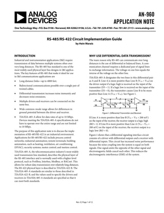
1. AN-960
APPLICATION NOTE
One Technology Way • P.O. Box 9106 • Norwood, MA 02062-9106, U.S.A. • Tel: 781.329.4700 • Fax: 781.461.3113 • www.analog.com
RS-485/RS-422 Circuit Implementation Guide
by Hein Marais
Rev. 0 | Page 1 of 12
INTRODUCTION
Industrial and instrumentation applications (I&I) require
transmission of data between multiple systems often over
very long distances. The RS-485 bus standard is one of the
most widely used physical layer bus designs in I&I applica-
tions. The key features of RS-485 that make it ideal for use
in I&I communications applications are
• Long distance links—up to 4000 feet.
• Bidirectional communications possible over a single pair of
twisted cables.
• Differential transmission increases noise immunity and
decreases noise emissions.
• Multiple drivers and receivers can be connected on the
same bus.
• Wide common-mode range allows for differences in
ground potential between the driver and receiver.
• TIA/EIA-485-A allow for data rates of up to 10 Mbps.
Devices meeting the TIA/EIA-485-A specifications do not
have to operate over the entire range and are not limited
to 10 Mbps.
The purpose of this application note is to discuss the imple-
mentation of RS-485/RS-422 in an industrial environment.
Applications for RS-485/RS-422 include process control
networks; industrial automation; remote terminals; building
automation, such as heating, ventilation, air conditioning
(HVAC), security systems; motor control; and motion control.
TIA/EIA-485-A, the telecommunication industry’s most widely
used transmission line standard, describes the physical layer of
the RS-485 interface and is normally used with a higher-level
protocol, such as Profibus, Interbus, Modbus, or BACnet. This
allows for robust data transmission over relatively long distances.
The RS-422 physical layer is described in TIA/EIA-422-B. The
TIA/EIA-485-A standards are similar to those described in
TIA/EIA-422-B, and the values used to specify the drivers and
receivers in TIA/EIA-485-A standards are specified so that it
can meet both standards.
WHY USE DIFFERENTIAL DATA TRANSMISSION?
The main reason why RS-485 can communicate over long
distances is the use of differential or balanced lines. A com-
munication channel requires a dedicated pair of signal lines
to exchange information. The voltage on one line equals the
inverse of the voltage on the other line.
TIA/EIA-485-A designates the two lines in this differential pair
as A and B. Line A is more positive than Line B (VOA > VOB) on
the driver output if a logic high is received on the input of the
transmitter (DI = 1). If a logic low is received on the input of the
transmitter (DI = 0), the transmitter causes Line B to be more
positive than Line A (VOB > VOA). See Figure 1.
VOA VIAVOB VIB
VOD
B
A
DI
DE
RO
RE
07395-001
Figure 1. Differential Transmitter and Receiver
If Line A is more positive than line B (VIA − VIB > 200 mV)
on the input of the receiver, the receiver output is a logic high
(RO = 1). If Line B is more positive than Line A (VIB − VIA >
200 mV) on the input of the receiver, the receiver output is a
logic low (RO = 0).
Figure 1 shows that a differential signaling interface circuit
consists of a driver with differential outputs and a receiver with
differential inputs. This circuit has increased noise performance
because the noise coupling into the system is equal on both
signals. One signal emits the opposite of the other signal and
electromagnetic fields cancel each other. This reduces the
electromagnetic interference (EMI) of the system.
2. AN-960 APPLICATION NOTE
Rev. 0 | Page 2 of 12
TABLE OF CONTENTS
Introduction ...................................................................................... 1
Why Use Differential Data Transmission?.................................... 1
RS-485 or RS-422?............................................................................ 3
RS-422................................................................................................ 3
RS-485 and the Unit Load Concept ............................................... 3
Half-Duplex RS-485......................................................................... 4
Full-Duplex RS-485.......................................................................... 4
Termination....................................................................................... 5
No Termination........................................................................ 5
Parallel Termination................................................................. 5
AC Termination.........................................................................5
Stub Length................................................................................5
Data Rate and Cable Length ........................................................5
Fail-Safe Biasing.................................................................................6
Differential Input Threshold Voltage of a Receiver..............6
Open Fail-Safe ...........................................................................6
True Fail-Safe Receivers ...........................................................7
Isolation ..............................................................................................8
Transient Overvoltage Stress Protection ........................................9
References...........................................................................................9
3. APPLICATION NOTE AN-960
Rev. 0 | Page 3 of 12
RS-485 OR RS-422?
RS-422 is specified as a simplex multidrop standard, which
means that only one driver and up to ten receivers can be
connected to the same bus. If more than one driver needs to
be connected on the same bus, then RS-485 is recommended.
RS-485 is specified as a multipoint standard, which means up
to 32 transceivers can be connected on the same bus.
Figure 2 shows a typical RS-422 interface circuit. Although
an RS-485 circuit may appear similar, the main difference is
in the bus architecture. Figure 3 shows a typical RS-485 appli-
cation circuit.
RS-422
The RS-422 standard specifies data rates up to 10 Mbps and
line lengths of up to 4000 feet. A single driver can drive a
transmission line with up to 10 receivers. The common-mode
voltage (VCM) is defined as the mean voltage of A and B
terminals with respect to signal ground (VCM = (VIA + VIB)/2).
The RS-422 receivers can withstand a common-mode
voltage (VCM) of ±7 V. When all ten receivers are placed on the
bus, a maximum load condition occurs. The input impedance
of the RS-422 receiver must be larger than or equal to 4 kΩ.
RS-485 AND THE UNIT LOAD CONCEPT
The input impedance of the RS-485 receiver is specified as
larger than or equal to 12 kΩ. This impedance is defined as
having one unit load (UL). The RS-485 specification specifies
the capability to sustain up to 32 ULs.
Some RS-485 receivers are specified as having ¼ UL or
⅛ UL. A receiver specified to have ¼ UL means that the
receiver only loads the bus by ¼ of the standard UL and,
therefore, 4 times as many of these receivers can be connected
to the bus (4 × 32 = 128 nodes).
Similarly, if an RS-485 receiver is specified to have ⅛ UL,
the receiver only loads the bus by ⅛ of the standard UL and,
therefore, 8 times as many of these receivers can be connected
to the bus (8 × 32 = 256 nodes). See Table 1 for UL and receiver
input impedance details.
Many of the RS-485 transceivers characteristics are the same as
for RS-422. The common-mode voltage range for RS-485 is
expanded to −7 V to +12 V. The RS-485 transceivers must
withstand this common-mode voltage range while tristated
(disconnected from the bus).
An RS-485 system must have a driver that can be disconnected
from the transmission line when a particular node is not
transmitting. The DE (RTS) pin on the RS-485 transceiver
enables the driver when a logic high is set to DE (DE = 1).
Setting the DE pin to low (DE = 0) puts the driver in a tristate
condition. This effectively disconnects the driver from the
bus and allows other nodes to transmit over the same twisted
pair cable.
RS-485 transceivers also have an RE pin that enables/disables
the receiver. The DE and RE pins combined allow some RS-485
transceivers to be put into a low power shutdown mode. This is
important for battery-powered applications.
Table 1. UL Receiver Input Impedance
Unit Load No. of Nodes Min. Receiver Input Impedance
1 32 12 kΩ
½ 64 24 kΩ
¼ 128 48 kΩ
⅛ 256 96 kΩ
RT ROR10DI D
R5
RO
RO
R9
R4
RO
RO
R8
R3
RO
RO
R7
R2
RORO
R1
RO
R6
07395-002
Figure 2. Typical RS-422 Interface Circuit
4. AN-960 APPLICATION NOTE
Rev. 0 | Page 4 of 12
RO
RE
DE
A
HALF-DUPLEX RS-485
Half-duplex RS-485 links have multiple drivers and receivers on
the same signal path. This is the reason why RS-485 transceivers
must have driver/receiver enable pins enabling only one driver
to send data at a time. See Figure 3 for a half-duplex bus config-
uration. This configuration is also known as a 2-wire RS-485
network connected in a multipoint configuration and allows for
data transmission in both directions, but only in one direction
at a time.
FULL-DUPLEX RS-485
Figure 4 shows an example of an RS-485 bus connected in
a full-duplex bus configuration. This configuration is also
known as a 4-wire RS-485 network connected in a multipoint
master/slave configuration. Full-duplex RS-485 allows for
simultaneous communication in both directions between
master and slave nodes.
DI
GND
B
RT RT
R
D
RO
RE
DE
A
DI
GND
B
R
D
RO DE DI
GND
R
D
A B
RE RO DE DI
GND
R
D
A B
RE
. . . .
07395-003
Figure 3. Half-Duplex RS-485 Bus Configuration
RO
RE
GND
RT
AVSL
RT DRO
RE
DE
DI
GND
R
R
D
RO DE DI
GND
R
D
A B Z Y
RE RO DE DI
GND
R
D
A B Z Y
RE
. . . . . . .
Y
Z
A
B
A
B
Z
Y
07395-004
DE
DI
SLAVE SLAVE
EMASTER
Figure 4. Full Duplex RS-485 Bus Configuration
5. APPLICATION NOTE AN-960
Rev. 0 | Page 5 of 12
( )
TERMINATION
In a transmission line, there are two wires, one to carry the
currents from the driver to the receiver and another to provide
the return path back to the driver. RS-485 links are a little more
complicated because of the fact that they have two signal wires
that share a termination as well as a ground return path.
However, the basic principles of transmission lines are the same.
For reliable RS-485 and RS-422 communications, it is essential
that the reflections in the transmission line be kept as small as
possible. This can only be done by proper cable termination.
Reflections happen very quickly during and just after signal
transitions. On a long line, the reflections are more likely to
continue long enough to cause the receiver to misread logic
levels. On short lines, the reflections occur much sooner and
have no effect on the received logic levels.
In RS-422 applications there is only one driver on the bus and
if termination is to be used it must be placed at the end of the
cable near the last receiver. RS-485 applications require termin-
ation at the master node and the slave node furthest from the
master. Table 2 shows a comparison of different termination
techniques.
No Termination
The time required for a signal to propagate down the line to a
receiver determines if a line is considered a transmission line.
Physically long wires have longer propagation times, whereas
physically short wires have shorter propagation times. When
the propagation time is short relative to the data bit duration,
the effect on the signal quality is minimized. A cable is not seen
as a transmission line if the signal rise time is more than four
times the propagation delay of the cable.
Parallel Termination
When two or more drivers share a pair of wires, each end of
the link has a termination resistor equal to the characteristic
impedance of the cable. There should be no more than two
terminating resistors in the network regardless of how many
nodes are connected.
In a half-duplex configuration, both ends of the cable must be
terminated (see Figure 3). In a full duplex configuration only
the master receiver and most remote slave receiver need to be
terminated.
AC Termination
AC termination is used to reduce the power consumption of
idle links as well as to reduce ringing voltages. The negative
effect though is a reduction in cable length and bit rate. A
resistor and capacitor can be placed in series across the bus
(between A and B) as shown in Figure 5. The Capacitor CT is
selected by using the following formula:
Ω
(ps))2(
(pF)CT
ancestic ImpedCharacteri
ble DelayOne-Way Ca
>
B
A
DI RO
RE
07395-005
RT
DIFFERENTIAL
DRIVER
DIFFERENTIAL
RECEIVER
Figure 5. Parallel Termination
B
A
DI RO
RE
07395-006
RT
CT
DIFFERENTIAL
DRIVER
DIFFERENTIAL
RECEIVER
Figure 6. AC Termination
Table 2. Termination Advantages and Disadvantages
Termination Advantages Disadvantages
None Simple, low power Suitable only for short
links with slow drivers
Parallel Simple High power
AC Low power Suitable only for low bit
rates and short links
Stub Length
Stub length should be much less than ¼ of a wavelength of the
frequency equal to the inverse of the bit period.
DATA RATE AND CABLE LENGTH
When high data rates are used, the application is limited to a
shorter cable. It is possible to use longer cables when low data
rates are used. The dc resistance of the cable limits the length of
the cable for low data rate applications by increasing the noise
margin as the voltage drop in the cable increases. The ac effects
of the cable limit the quality of the signal and limit the cable
length to short distances when high data rates are used.
Examples of data rate and cable length combinations vary from
90 kbps at 4000 feet to 10 Mbps at 15 feet for RS-422.
Figure 7 can be used as a conservative guide for cable length vs.
data rate.
10000
1000
100
10
10k 100k 1M 10M
CABLELENGTH(Feet)
07395-016
DATA RATE (bps)
Figure 7. Cable Length vs. Data Rate
6. AN-960 APPLICATION NOTE
RO
RE
DE
DI
A
B
Rev. 0 | Page 6 of 12
RT RT
R
D
RO
RE
DE
DI
A
B
R
D
RO DE DI
R
D
A B
RE RO DE DI
R
D
A B
RE
07395-007
ACCELERATION
MICRO-
PROCESSOR
AND
UART
MICRO-
PROCESSOR
AND
UART
MASTER SLAVE
MICROPROCESSOR
AND
UART
MICROPROCESSOR
AND
UART
TEMPERATUREPRESSURE
SLAVESLAVE
Figure 8. Master/Slave RS-485 Network with No Fail-Safe Biasing of the Network
FAIL-SAFE BIASING
Figure 8 shows a configuration of a master/slave RS-485
network with no fail-safe biasing. Asynchronous data
transmission is typically used in these applications. A start bit
indicates the start of a bit sequence and is detected when a
transition occurs from high to low. Eight data bits and a parity
bit follow the start bit. A stop bit that can be one or two bits
long follows this bit sequence. Another start bit starts the next
bit sequence. When the last character is sent the line should stay
high until the next start bit. This causes problems in multipoint
applications when the transceivers connected on the bus are in
receive mode simultaneously. This is known as a bus idle
condition and in this case, the differential voltage on the bus
(VOA − VOB) is 0 V. Under this condition, the receiver output
(RO) is undefined by the RS-485 standard and, thus, the
receiver output can produce random data. This data is
connected to the UART and can cause erroneous system
operation.
Differential Input Threshold Voltage of a Receiver
The differential input threshold voltage (VTH) of a receiver is the
voltage on the receiver input at which a transition (low to high
or high to low) of the receiver output is guaranteed. A typical
RS-485 transceiver has a differential input threshold voltage
of ±200 mV. What this means is that when the differential
input is larger than or equal to 200 mV (VIA – VIB ≥ 200 mV),
the receiver output is guaranteed to be high (RO = 1). When
the differential input is less than or equal to −200 mV
(VIA – VIB < −200 mV), the receiver output is guaranteed to
be low (RO = 0). See Table 3 for a truth table for the receiver.
Table 3. Differential Receiver Truth Table
RE A − B (Inputs) RO
0 ≥+200 mV 1
0 ≤−200 mV 0
0 −200 mV ≤ (A − B) ≤ +200 mV X
1 X High-Z
Open Fail-Safe
During the bus idle condition, there is no device driving the
bus. The receiver output is undefined. This can cause random
data to be received on the UART, which in turn can cause false
start bits, false interrupts, and framing errors.
This problem can be solved by placing a combination of pull-up
and pull-down resistors at one position on the bus. Figure 9
shows the biasing resistor circuit. An example of calculating R1
and R2 is shown below (assume RT = 120 Ω):
R1 = R2 = R
VIA – VIB ≥ 200 mV
VIA – VIB = RT
T
CC
RR
V
+2
= 200 mV
if VCC = 5 V, then R = 1440 Ω
if VCC = 3 V, then R = 960 Ω
If lower values for R are used (VIA − VIB > 200 mV), a greater
noise margin can be achieved in the system. See Figure 10 for a
graphical representation of the bus states and differential input
voltage.
7. APPLICATION NOTE AN-960
Rev. 0 | Page 7 of 12
RT
R1
R2
RO
RE
DE
DI
A
B
R
D
07395-008
MICRO-
PROCESSOR
AND
UART
GND
VCC
Figure 9. Fail-Safe Biasing Circuit
FAIL SAFE
NOISE MARGIN
TIME
TIME
RECEIVER OUTPUT STATE
LOGIC 0 LOGIC 1
RECEIVER
OUTPUT
UNDEFINED
+200mV
0V
–200mV
VOH
VOL
DIFFERENTIALINPUTVOLTAGE
(VIA–VIB)
RECEIVEROUTPUT(RO)
07395-009
07395-010
Figure 10. Differential Input Voltage and the Receiver Output State
True Fail-Safe Receivers
New generation RS-485 transceivers have an improved feature
that includes true fail-safe receiver inputs. This eliminates the
need for pull-up/pull-down resistors as shown in the previous
example. If a transceiver is specified to have a true fail-safe
feature this means that, the differential input threshold voltage
(VTH) has been adjusted from ±200 mV to −200 mV to −30 mV
(see Figure 11).
During the bus idle condition, VIA – VIB = 0 and therefore is
larger than −30 mV, resulting in the receiver output being high
(RO = 1). This means that if all transceivers connected to the
bus have true fail-safe features, the receiver output is always
defined. See Figure 12 for a graph of the bus states and
differential input voltage.
DIFFERENTIALINPUTVOLTAGE(VIA–VIB)[V]
LOGIC 1
LOGIC 0
UNDEFINED
STANDARD
RS-485 RECEIVER
LOGIC 1
LOGIC 0
UNDEFINED
TRUE
FAIL-SAFE
RS-485 RECEIVER
0.2
0
–0.03
0.4
–0.2
–0.4
Figure 11. Input Threshold Voltage
OPEN/SHORT
FAIL SAFE
TIME
TIME
RECEIVER OUTPUT STATE
LOGIC 0 LOGIC 1
RECEIVER
OUTPUT
UNDEFINED
–30mV
0V
–200mV
VOH
VOL
DIFFERENTIALINPUTVOLTAGE
(VIA–VIB)
RECEIVEROUTPUT(RO)
07395-011
Figure 12. Differential Input Voltage and Receiver Output State
8. AN-960 APPLICATION NOTE
07395-012
ISOLATION
In RS-485 applications, there are often long links, which can
cause the ground potential at different nodes on the bus to be
slightly different. This causes ground currents to flow through
the path of least resistance through either the common earth
ground or the ground wire. If the same electrical system is
used to connect the power supplies of all nodes to the same
earth ground, the ground connection may have reduced noise.
Note, however, that motors, switches, and other electrically
noisy equipment can still induce ground noise into the system.
When different nodes are situated in different buildings,
different power systems are required. This is likely to increase
the impedance of the earth ground and the ground currents
from other sources are more likely to find their way into the
link’s ground wire. Isolating the link reduces or even eliminates
these problems. Galvanic isolation is a perfect solution if there
is no guarantee that the potential at the earth grounds at
different nodes in the system are within the common-mode
range of the transceiver. Galvanic isolation allows information
flow, but prevents current flow (see Figure 13).
ISOLATORPOINT A POINT B
ISOLATION
BARRIER
INFORMATION FLOW
NO GROUND CURRENT FLOW
PROTECT HUMANS/
EQUIPMENT
ELIMINATE GROUNDING
PROBLEMS
IMPROVE SYSTEM
PERFORMANCE
Figure 13. Galvanic Isolation Allows Information Flow While Preventing
Ground Current Flow
The signal lines, as well as the power supply, must be isolated.
Power isolation is achieved by an isolated dc-dc supply, such as
Analog Devices, Inc. isoPower™, and signal isolation is achieved
via Analog Devices iCoupler
®
technology. See Figure 14 for an
example of how to achieve signal and power isolation using the
ADM2485.
Rev. 0 | Page 8 of 12
07395-013
D
RDECODE ENCODE
ENCODE DECODE
ENCODE DECODE
OSC
ADP3330
OUT
SD
IN
ERRGND
ADM2485
22µFVDD1 10µF
LDO
100nF
+5V ISO
GND2
RECTIFIER
5V CENTER TAPPED
TRANSFORMER
DA2303-AL
1:11.5
RS-485 CABLE
100nF
LOCAL
POWER
SUPPLY
5V
TxD
RTS
RxD
RE
UART
VDD1
GND1
GND1 ISOLATION
BARRIER
DIGITAL ISOLATION RS-485 TRANSCEIVERiCoupler
GND2
DE OUT
A
B
VDD2
D1 D2
RT
Figure 14. Signal and Power Isolation using the ADM2485
9. APPLICATION NOTE AN-960
Rev. 0 | Page 9 of 12
TRANSIENT OVERVOLTAGE STRESS PROTECTION
In I&I applications, lightning strikes, power source fluctuations,
inductive switching, and electrostatic discharge can cause
damage to RS-485 transceivers by generating large transient
voltages. The following ESD protection, EFT protection, and
surge protection specifications are relevant to RS-485
applications:
• IEC 61000-4-2 ESD protection
• IEC 61000-4-4 EFT protection
• IEC 61000-4-5 surge protection
Analog Devices offers a broad range of RS-485 devices with
enhanced ESD protection. An E appended to the part number,
such as ADM3072E, indicates enhanced ESD protection. For a
full range of the Analog Devices RS-485 portfolio, refer to
http://www.analog.com/RS485.
The level of protection can be further enhanced when using
external clamping devices, such as TVS diodes. TVS diodes
are normally used to protect silicon devices, like RS-485
transceivers, from transients. The protection is accomplished
by clamping the voltage spike to a limit, by the low impedance
avalanche breakdown of a PN junction. TVS diodes are ideally
open-circuit devices. A TVS diode can be modeled as a large
resistance in parallel with some capacitance while working
below its breakdown voltage. When a transient is generated and
the surge voltage is larger than the breakdown voltage of the
TVS, the resistance of the TVS decreases to keep the clamping
voltage constant. The TVS clamps the pulse to a level that does
not damage the device that it is protecting. The transients are
clamped instantaneously (< 1 ns) and the damaging current is
diverted away from the protected device (see Figure 15).
The function of a TVS in RS-485 applications is to clamp the
voltage on the bus to the common-mode voltage range of the
RS-485 transceiver (−7 V to +12 V). Some TVS devices have
been specifically designed for RS-485 applications. For higher
power transients, protection can be increased by adding
Resistors RS (between 10 Ω and 20 Ω) between the protected
device and the input pin as shown in Figure 15 and Figure 16.
10Ω TO
20Ω
PROTECTED
DEVICETVSTRANSIENT
CURRENT
7395-0140
Figure 15. Transient Voltage Supressor
RT
RO
RE
DE
DI
A
B
R
D
07395-015
MICRO-
PROCESSOR
AND
UART
RS
RS
TVS
RS-485 TRANSCEIVER
Figure 16. TVS Application Circuit
REFERENCES
ANSI/TIA/EIA-485-A-1998: Electrical Characteristics of
Generators and Receivers for use in Balanced Digital Multipoint
Systems.
ANSI/TIA/EIA-422-B-1994: Electrical Characteristics of
Balanced Voltage Digital Interface Circuits.
Axelson, Jay. 1998. Serial Port Complete : Programming and
Circuits for RS-232 and RS-485 Links and Networks, Lakeview
Research.
Clark, Sean. 2004. AN-727, iCoupler®
Isolation in RS-485
Applications Application Note. Analog Devices, Inc. (June).