
Recommended
More Related Content
What's hot
What's hot (20)
Similar to Pinion mount
Similar to Pinion mount (20)
Recently uploaded
Recently uploaded (20)
Pinion mount
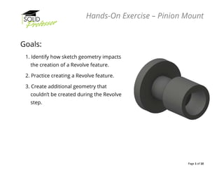
- 1. Hands-On Exercise – Pinion Mount Page 1 of 10 Goals: 1. Identify how sketch geometry impacts the creation of a Revolve feature. 2. Practice creating a Revolve feature. 3. Create additional geometry that couldn’t be created during the Revolve step.
- 2. Hands-On Exercise – Pinion Mount Page 2 of 10 Instructions: 1. Begin a new part file using the Standard (mm).ipt template. 2. Start a new sketch on the XY plane and sketch a horizontal line that begins on the origin. This will be the axis of revolution for the Revolve Feature. 3. Sketch a chain of vertical and horizontal lines to make the following shape.
- 3. Hands-On Exercise – Pinion Mount Page 3 of 10 Instructions: (continued) 4. Add the following smart dimensions to make the sketch fully constrained.
- 4. Hands-On Exercise – Pinion Mount Page 4 of 10 Instructions: (continued) 5. Launch the Revolve command from the Create panel of the 3D Model Ribbon. a. Select the bottom line in the sketch as the axis of revolution. b. Extents option should be set to “Full”.
- 5. Hands-On Exercise – Pinion Mount Page 5 of 10 Instructions: (continued) 6. To begin creating the alignment feature on the part, start a new sketch on the flat surface as shown.
- 6. Hands-On Exercise – Pinion Mount Page 6 of 10 Instructions: (continued) 7. Use the Circle tool and the Line tool to create the geometry shown.
- 7. Hands-On Exercise – Pinion Mount Page 7 of 10 Instructions: (continued) 8. Optional: Use the Trim command found in the Modify panel to trim away the top segment of the circle. 9. Add dimensions to fully constrain the sketch as shown in the image. (Note: If the top arc segment was trimmed away, the dimension for the circle will appear as a radius. If the arc segment wasn’t trimmed, the dimension will appear as a diameter and should be double the radius value shown in the image.)
- 8. Hands-On Exercise – Pinion Mount Page 8 of 10 Instructions: (continued) 10. Once the sketch is fully constrained, launch the Extrude command. 11. Enter a depth of 25 mm using the “Distance” Extent option cutting into the part.
- 9. Hands-On Exercise – Pinion Mount Page 9 of 10 Instructions: (continued) 12. Change the part material to “Steel” using the drop-down list at the top of Inventor.
- 10. Hands-On Exercise – Pinion Mount Page 10 of 10 Self-Check: 1. Check the mass of the Part by expanding the Solid Bodies folder in the Browser, then right clicking on the Solid Body and selecting Properties from the menu. In the following dialog box click Update. Does the mass equal 0.529 kg? • If so, Good Job! • If not, double check that the part is using metric units, and that the material is set to Steel. Also edit each feature to ensure that none of the sketches are under-defined and that the status bar displays “Fully Constrained” in the lower right corner.