SlideShare a Scribd company logo
1 of 48
Download to read offline
Motors | Automation | Energy | Transmission & Distribution | Coatings
Automation
Contactors - CWB Line
Summary
Contactors - CWB Line
Presentation 04
Selection Table 15
Application Forms 21
16Accessories
42Dimensions
34Technical Data
Developed according to IEC/EN 60947 and UL 508 international standards, the WEG CWB line of
contactors meets the requirements of a wide range of industrial applications worldwide.
Characteristics
JJ Currents from 9 to 80 A (AC-3);
JJ Power supply from 24 V to 690 V ac/dc;
JJ Low-consumption coils, 5.8 W at 24 V dc;
JJ Compact, 18% smaller than the CWM line;
JJ Built-in auxiliary contacts 1 NO and 1 NC;
JJ Easy mounting of surge suppressor blocks;
JJ Easy identification of the control voltage;
JJ “Zero-width” mechanical interlock;
COMPACT IN SIZE.
GIANT IN TECHNOLOGY.
JJ Easy-connection busbar for quick mounting of more compact
reversing and star-delta starters;
JJ Possibility to mount compact starters with MPW18, MPW40 and
MPW80 manual motor protectors, and RW27-2D and RW67-5D
thermal relays;
JJ Choice of up to six auxiliary contacts;
JJ Compatibility of accessories with the whole CWB line;
JJ Fast mounting on DIN rail 35mm or with screw.
Contactors - CWB Line4
Suitable for different applications
Benefits
Modular and compact
Internationally-recognized quality
Simplified installation Energy saving
Highly reliable
Certifications
1) 1)1)
Note: 1) Certification for CWB40-80 in progress.
Russia MexicoSouth AfricaArgentinaCanada and USAEuropean
Union
Contactors - CWB Line 5
Analysis of CWB electromagnetic system Process manufacturing simulation to ensure high quality of the
injected parts
Technology within your Reach
The use of finite-element analysis and state-of-the-art modeling softwares for simulation of
electromagnetic and electromechanical systems provide WEG CWB contactors with an improved
project with reduced contact bouncing. The outcome reached by WEG’s RD team ensures a product
with long mechanical and electrical lifespan in a reduced size and with lower energy consumption.
The electric contacts of CWB contactors are manufactured with special silver alloys which ensure excellent electric
conductibility and high contact reliability. During operation, the double-break contacts and arc chutes ensure fast arc
quenching and provide high resistance against the wear effects of the electric arc and, consequently, a long electrical lifespan.
Manufactured with the best raw materials and high-quality parts, the CWB line uses high-precision injection molds and
metal stamping tools, ensuring very reliable products with the best cost-benefit on the market.
Contactors - CWB Line6
Energy Savings
Low Consumption Coils
The low-consumption coils of the CWB contactors
enable safe operation with minimum energy
consumption of up to 5.8 W in direct current, and up
to 7.5 VA in alternating current. In addition to the
energy saving, the low consumption of the contactor
coils allows reducing the supply of control
transformers. When well dimensioned and properly
applied, the traditional electric motor starting
methods, such as direct (reversing and non-
reversing) and star-delta starters that use contactors,
are the safest and the best cost-benefit options to
start and protect low-voltage electric motors. Up to
at least 55 kW, direct starters and star-delta starters
that use contactors are still the best and most
common starting method in all kinds of industry in
the whole world. Even when electronic methods are
used to start and control motors, such as frequency
inverters and soft-starters, contactors are still
necessary in combination with the electronic
devices.
Consequently, we can imagine the huge number of
contactors installed and in operation, consuming
energy in the whole world.
Therefore, the CWB contactors were designed to
operate safe and reliably with the lowest energy
consumption.
Coil Consumption
DC Operated Contactor
Standard contactor CWB
Green
Manufactured with nontoxic and low-impact materials, the CWB
line of contactors is safe and sustainable, complying with the
RoHS international requirements.
DC Coils
In addition to the low energy consumption, the DC
coils enable direct control of the CWB contactors
via PLC or digital outputs of devices such as
frequency inverters or-starters without relay
interfaces.
Standard contactor
Coil consumption
DC Closed Contactor
Energy
saving
30%
CWB
www.weg.net
Contactors - CWB Line 7
Easy Panel Optimization
18% 
45 mm 54 mm
Allows
+ 1
Contactor
Allows
+ 1
Contactor
55 mm 60 mm
Compact Solution
As they are compact, 45 mm wide available in up to 38 A (18.5 kW at 380 V AC-3 three-phase), and 54 mm wide available
from 40 to 80 A (37 kW at 380 V AC-3 three-phase), the CWB contactors provide a general reduction in size of electrical
panels in comparison to traditional solutions with contactors of the same specification.
Built-In Auxiliary Contacts 1NO + 1NC
The configuration of two built-in auxiliary contacts
(1NO + 1NC) makes the application of CWB contactors
more flexible in most automation systems, contributing
to the optimization of internal space of electrical panels.
More Simple and Organized Control Circuits
In order to optimize the space in electrical panels even
more, the CWB line of contactors has a front slot for
passing control cables. That can reduce or eliminate the
necessity of routing control cables through the side or
front part of the contactors, providing a cleaner and
more organized assembly of the control circuit.
Standard ContactorsCWB Line
Side by side mounting CWB38 Side by side mounting CWB80
www.weg.net
Contactors - CWB Line8
Easy Panel Optimization
“Zero-Width” Mechanical Interlock
For applications which require a mechanical interlock between contactors, WEG developed a new mechanical system that
ensures compact and safe mounting without any tools. The new WEG mechanical interlocking system enables the mechanical
interlock between the contactors of the CWB line without adding side space, and it is possible to mount reversing starters of
up 80 A.
90 mm
(2 x 45 mm)
Simple and Compact Mounting of Surge
Suppressor Blocks
The coils of CWB contactors operate smoothly with
a low level of disturbance in the control circuits.
However, in order to reduce voltage surges due to
the coil switching even further, WEG has developed
surge suppressor blocks especially for the CWB line
of contactors, which ensure limitation or even
completely eliminate the undesired interferences
that may be caused on opening the contactor coil.
Surge suppressor blocks are easily mounted on
CWB contactors without the need of any kind of
tools and also without increasing volume.
Contactor Coil Operated on AC or DC
A wide range of voltages available in only two coil
versions (one for AC and another for DC) for the whole
line of contactors from 9 to 80 A. With easy
replacement of the AC coil in currents from 9 to 80 A
and DC coils in currents from 40 to 80 A with visual
indication of the coil voltage.
CWB9...38 A
AC coil
CWB9...80 A
DC coil
CWB40...80 A
AC coil
108 mm
(2 x 54 mm)
www.weg.net
Contactors - CWB Line 9
Flexibility and Modularity in Assembly of Electric Panels
Easy-Connection Busbars and Connectors
The smooth integration between the CWB contactor line, overload relays and manual motor protectors enables simple and
quick mounting of compact starters, besides protection sets for low-voltage electric motors with excellent cost effectiveness.
The modularity and flexibility of the easy-connection busbars and connectors reduce the mounting time, also preventing
possible errors. Available for the whole CWB line, the easy-connection system allows the mounting combined with WEG
manual motor protectors and overload relays, forming compact and robust direct starters, reversing and non-reversing
starters, in addition to star-delta starters.
Contactors - CWB Line10
Additional Contact Blocks
Besides the 1NO + 1NC built-in auxiliary contacts, in order to meet the most complex control needs, WEG has also developed
auxiliary high performance contact blocks which can be easily mounted on the front or side of CWB contactors, allowing the
combination of up to six auxiliary contacts per contactor up to 80 A.
An important characteristic of the side auxiliary contact blocks of the CWB line is the small dimension (only 9 mm wide) which
meets the requirements of modularity, allowing more compact combinations of motor starters with motor protective circuit
breakers when easy-connection busbars are used.
Panel Assembly Flexibility
CWB contactors can be easily assembled on panels
using 35 mm DIN rails or screws because their
oblong holes are compatible with the old and
traditional lines of contactors on the market.
Easy Access Power and Control Terminals
All power terminals, auxiliary contacts and coils provide users with fast front access, facilitating installation, measurements and
interventions for preventive and corrective maintenance of starters.
Contactors - CWB Line 11
Construction Characteristics
Power contacts,
easily identified
Control terminals
asymmetrically arranged in
relation to the auxiliary
contacts, preventing
misconnections
Auxiliary contacts incorporated,
easily identified and separated from
the power contacts, preventing
misconnections
Easy mounting of surge suppressor
block without adding volume
Mounting with
screws
Indelible labeling of the
technical data to help the
user use the product properly
Opening for mechanical
interlock
DIN rail mounting
www.weg.net
Contactors - CWB Line12
Applications
The characteristics of the CWB contactors make them suitable for applications in many different segments.
Paper  Cellulose Wood Cement MiningChemical and Petrochemical
Steel Oil  Gas
Refrigeration
Sugar  Alcohol Fans
Machines and Processes in General
Irrigation and Pumping Systems
Civil Construction Load Lifting Automation
www.weg.net
Contactors - CWB Line 13
Reliability and Safety
Safety Against Accidental Contact
All the power and control terminals of the CWB contactors have degree of protection that ensure total safety against accidental
front contacts.
Safety-Related Applications
In automation systems of machines and equipment, it is common to use special contactors in combination with specific
safety relays. The CWB line allows such combination due to the arrangement of the contacts, which comply with the
requirements of IEC/EN 60947-4-1 Annex F (Mirror Contacts) and IEC/EN 60947-5-1 Annex L (Mechanically Linked Contacts
and NR12 regulatory standard).
IEC/EN 60947-5-1
Mechanically linked
contacts
IEC/EN 60947-4-1
Mirror contacts
Contactors - CWB Line14
Selection Table
Ie max.
(Ue ≤440 V)
Ie = Ith
(Ue ≤690 V)
θ ≤55 °C
Orientative rated operational power in AC-31)
Three-phase motor - IV poles - 60 Hz - 1,800 rpm
Auxiliary contacts per contactor
Reference to fill in with
the control voltage
Weight2)
kg
AC-3
A
AC-1
A
220 V
230 V
kW / hp
380 V
400 V
kW / hp
415 V
440 V
kW / hp
500 V
kW / hp
660 V
690 V
kW / hp
4
3
NO
2
1
NC
9 25 2.2 / 3 3,7 / 5 4.5 / 6 5.5 / 7.5 5.5 / 7.5 1 1 CWB9-11-30♦ 0.372
12 25 3 / 4 5.5 / 7.5 5,5 / 7,5 7.5 / 10 7.5 / 10 1 1 CWB12-11-30♦ 0.372
18 32 4.5 / 6 7.5 / 10 9.2 / 12.5 9,2 / 12,5 11 / 15 1 1 CWB18-11-30♦ 0.372
25 40 5,5 / 7,5 11 / 15 11 / 15 15 / 20 15 / 20 1 1 CWB25-11-30♦ 0.408
32 50 7.5 / 10 15 / 20 15 / 20 18.5 / 25 18.5 / 25 1 1 CWB32-11-30♦ 0.408
38 50 9.2 / 12.5 18.5 / 25 18.5 / 25 18.5 / 25 18.5 / 25 1 1 CWB38-11-30♦ 0.408
40 60 11 / 15 18.5 / 25 22 / 30 22 / 30 30 / 40 1 1 CWB40-11-30♦ 0.91
50 90 15 / 20 22 / 30 30 / 40 30 / 40 30 / 40 1 1 CWB50-11-30♦ 0.91
65 110 18.5 / 25 30 / 40 37 / 50 37 / 50 37 / 50 1 1 CWB65-11-30♦ 0.91
80 110 22 / 30 37 / 50 45 / 60 55 / 75 45 / 60 1 1 CWB80-11-30♦ 0.91
Replace “♦” by the appropriate coil voltage code3).
Alternating Current
Direct Current
Code D02 D07 D13 D23 D24 D25 D33 D34 D35 D36 D39
V (50/60 Hz) 24 48 110 220 230 240 380 400 415 440 480
Code C03 C07 C09 C12 C13 C15
V dc 24 48 60 110 125 220
Notes: 1) Orientative values.
2) Weight for contactors with control circuit in alternate current. For control circuit in direct current, add 0.121 kg to the alternating-current models.
3) Other voltages on request.
Three-Pole from 9 A to 80 A (AC-3)
NEW
Contactors - CWB Line 15
Accessory Overview
1 - Contactors CWB40...80
2 - Zero mechanical interlocking set (IM2)
3 - Side mounted auxiliary contact blocks BLRB
4 - Side mounted auxiliary contact blocks BLB
5 - Contactors CWB9...38
6 - Zero mechanical interlocking set (IM1)
1
3
4
5
2
9
10
6
1
www.weg.net
Contactors - CWB Line16
Accessory Overview
7 - Front mounted auxiliary contact blocks BFB
8 - Surge suppressor blocks
9 - Busbar for quick connections for reversing starters (EC-R-1)
10 - Busbar for quick connections for star-delta starters (EC-SD-1)
11 - Busbar for quick connections for reversing starters (EC-R-2)
12 - Busbar for quick connections for star-delta starters (EC-SD-2)
7
11 12
3
4
5
8
7
www.weg.net
Contactors - CWB Line 17
Front Mounted Auxiliary Contact Blocks
Side Mounted Auxiliary Contact Block
Illustrative picture For use with
Max. nº of additional
contacts / contactor
Auxiliary contacts
Reference Code
Weight
kgNO NC
CWB9...38
CWB40...80
4 / CWB9...38
4 / CWB80...80
Auxiliary contact blocks according to IEC/EN 60947
1 1 BFB-111) 12123053
0.063
2 0 BFB-20 12122434
0 2 BFB-021) 12122946
2 2 BFB-221) 12123051
22) 22) BFB-22 EL2) 12771537
4 0 BFB-40 12122947
0 4 BFB-041) 12123048
3 1 BFB-311) 12123049
1 3 BFB-131) 12123052
Auxiliary contact blocks according to EN 50012
1 1 BFB-11 EN1) 12979242
0.063
2 0 BFB-20 EN 12979240
0 2 BFB-02 EN1) 12979241
2 2 BFB-22 EN1) 12979246
4 0 BFB-40 EN 12979243
0 4 BFB-04 EN1) 12979244
3 1 BFB-31 EN1) 12979245
1 3 BFB-13 EN1) 12979247
Illustrative picture For use with
Max. nº of additional
contacts / contactor
Auxiliary contacts
Reference Code
Weight
kgNO NC
CWB9...38
CWB40...80
2 / CWB9...38
2 / CWB40...80
1 1 BLB-111) 12187899
0.034
2 0 BLB-20 12187334
0 2 BLB-021) 12187898
1 1 BLRB-111)3) 12230321
2 0 BLRB-203) 12230319
0 2 BLRB-021)3) 12230320
Plug-In Surge Suppressors
Notes: 1) They comply with the requirements of IEC/EN 60947-4-1 about mirror contacts and the requirements of IEC/EN 60947-5-1 about mechanically linked contacts.
2) BFB-22-EL: besides the regular contacts NO and NC, there are two special contacts: early make and late break.
3) For side mounting of two side-auxiliary contact blocks on the same contactor side.
4) Contactors assembled with surge suppressor DIB will increase in 6 times the opening time.
5) Contactors assembled with surge suppressor DIZB will increase in 4 times the opening time.
Accessories
Illustrative picture For use with Voltage Diagram Reference Code
Weight
kg
CWB9...38
CWB40...80
24...48 V 50/60 Hz RCBD53 12242511
0.008
50...127 V 50/60 Hz RCBD55 12242512
130...250 V 50/60 Hz RCBD63 12242513
12...48 V 50/60 Hz /
12...60 V dc
VRBE49 12242514
50...127 V 50/60 Hz /
60...180 V dc
VRBE34 12242515
130...250 V 50/60 Hz /
180...300 V dc
VRBE50 12242516
277...380 V 50/60 Hz /
300...510 V dc
VRBE41 12242517
400...510 V 50/60 Hz VRBD73 12242558
12...600 V dc DIBC334) 12242560
12...250 V dc DIZBC265) 12242561
www.weg.net
Contactors - CWB Line18
Accessories
Mechanical Interlock
Easy-Connection Setting of the Power Terminals for Reversing Starters
Illustrative picture
For use with
Orientative rated operational power for reversing starters (AC-4 duty)
for three-phase 4-pole motors - 60 Hz - 1,800 pm
Reference Code
Weight
kg
K1=K2
230 V
kW / cv
400 V
kW / cv
CWB9 1.5 / 2.0 2.2 / 2.9
EC-R-1 12241229 0.042
CWB12 1.5 / 2.0 3.7 / 5.0
CWB18 2.2 / 2.9 4 / 5.4
CWB25 3 / 4.0 5.5 / 7.4
CWB32 4 / 5.4 7.5 / 10.1
CWB38 4 / 5.4 7.5 / 10.1
CWB40 4.5 / 6.0 9.2 / 12.3
EC-R-2 13619637 0.073
CWB50 5.5 / 7.4 11 / 14.7
CWB65 7.5 / 10.1 15 / 20.1
CWB80 11 / 14.7 18.5 / 24.8
Illustrative picture
For use with
Orientative rated operational power in AC-3
Three-phase motor - IV poles - 1,800 rpm
Reference Code
Weight
kg
K1=K2 K3
230 V
kW / cv
400 V
kW / cv
CWB9 CWB9 4 / 5.4 7.5 / 10
EC-SD-1 12241230 0.046
CWB12 CWB9 5.5 / 7.5 11 / 15
CWB18 CWB12 9.2 / 12.5 15 / 20
CWB25 CWB18 11 / 15 22 / 30
CWB32 CWB18 15 / 20 -
CWB38 CWB25 18.5 / 25 30 / 40
CWB50 CWB40 22 / 30 45 / 61
EC-SD-2 13619635 0.036CWB65 CWB40 30 / 40 55 / 75
CWB80 CWB50 45 / 61 75 / 102
Power Terminal Easy-Connection Set for Star-Delta Starters
A1 A1
A2 A2
1L1
2T1 2T1
1L13L2
4T2 4T2
3L25L3
6T3 6T3
5L3
Electric diagram
1L1 1L1 1L13L2 3L2 3L25L3 5L3 5L3A1 A1
A2 A2 A2
2T12T1 2T14T24T2 4T26T36T3 6T3
A1
Electric diagram
Illustrative picture For use with Description Reference Code
Weight
kg
CWB9...38
Mounting set for interlocking two contactors with the same frame type.
Fitting through snaps without tools.
IM1 12244300
0.004
CWB40...80 IM2 13765620
www.weg.net
Contactors - CWB Line 19
Illustrative picture For use with Control type
Reference to fill in with
the control voltage
Code
Weight
kg
CWB9...38 AC BRB-38♦ On request 0.8
CWB40...80 AC BRB-80♦ On request 0.09
CWB40...80 DC BRB-80♦ On request 0.40
Spare Coils for Contactors1)
Alternating Current
Direct Current
Code D02 D07 D13 D23 D24 D25 D33 D34 D35 D36 D39
V (50/60 Hz) 24 48 110 220 230 240 380 400 415 440 480
Code C03 C07 C09 C12 C13 C15
V dc 24 48 60 110 125 220
Accessories
Replace “♦” by the appropriate coil voltage code.
Note: 1) Spare coil in direct current (DC) only for CWB40...80 A.
www.weg.net
Contactors - CWB Line20
Application Forms
Easy Installation
JJ Contactors, overload relays and manual motor protectors with a compact design up to 80 A (37 kW @ 380/415 V)
JJ Easy-connection bars for direct on-line, reversing and star-delta starters, saving mounting time
JJ Easy combination of all the starter parts
JJ Contactors with built-in auxiliary contacts 1NO + 1NC
Panel Optimization
JJ 45 mm wide up to 38 A
JJ 54 mm wide from 40 to 80 A
JJ 9 mm wide side contact blocks
JJ Compact starters
JJ “Zero” mechanical interlock without adding side space
JJ Simple and reliable parts
Easy Operation
JJ High performance and reliability for a wide range of applications
JJ Energy savings
JJ Without peak currents for contactors with DC coil
JJ Built-in overload and short circuit protections (when MPW is used)
Motor Starters
With the CWB contactors, the MPW manual motor protectors and the RW overload relays, WEG offers a complete line of
compact starters that stand out on the market.
www.weg.net
Contactors - CWB Line 21
Direct On-Line Starters
Motor current
(A)
AC-3 contactor Overload relay
CWB + RW27-2D /
CWB + RW67-5D
Total weight
(kg)
Reference
Maximum rated
current AC-3
(A)
Reference
Current I
adjustment range
(A)
Maximum fuse (gL/gG)
(coordination type 1)
(A)
0.28...0.4 CWB9-11-30♦ 9 RW27-2D3-D004 0.28...0.4 2 0.54
0.43...0.63 CWB9-11-30♦ 9 RW27-2D3-C063 0.43...0.63 2 0.54
0.56...0.8 CWB9-11-30♦ 9 RW27-2D3-D008 0.56...0.8 2 0.54
0.8...1.2 CWB9-11-30♦ 9 RW27-2D3-D012 0.8...1.2 4 0.54
1.2...1.8 CWB9-11-30♦ 9 RW27-2D3-D018 1.2...1.8 6 0.54
1.8...2.8 CWB9-11-30♦ 9 RW27-2D3-D028 1.8...2.8 6 0.54
2.8...4 CWB9-11-30♦ 9 RW27-2D3-U004 2.8...4 10 0.54
4...6.3 CWB9-11-30♦ 9 RW27-2D3-D063 4...6.3 16 0.54
5.6...8 CWB9-11-30♦ 9 RW27-2D3-U008 5.6...8 20 0.54
7...9 CWB9-11-30♦ 9 RW27-2D3-U010 7...10 25 0.54
8...12 CWB12-11-30♦ 12 RW27-2D3-D125 8...12.5 25 0.54
10...15 CWB18-11-30♦ 18 RW27-2D3-U015 10...15 35 0.54
11...17 CWB18-11-30♦ 18 RW27-2D3-U017 11...17 40 0.54
15...23 CWB25-11-30♦ 25 RW27-2D3-U023 15...23 50 0.57
22...32 CWB32-11-30♦ 32 RW27-2D3-U032 22...32 63 0.57
32...40 CWB38-11-30♦ 38 RW27-2D3-U040 32...40 90 0.57
25...40 CWB40-11-30♦ 40 RW67-5D3-U040 25...40 80 1.25
32...50 CWB50-11-30♦ 50 RW67-5D3-U050 32...50 100 1.25
40...57 CWB65-11-30♦ 65 RW67-5D3-U057 40...57 100 1.25
50...63 CWB65-11-30♦ 65 RW67-5D3-U063 50...63 100 1.25
57...70 CWB80-11-30♦ 80 RW67-5D3-U070 57...70 125 1.25
63...80 CWB80-11-30♦ 80 RW67-5D3-U080 63...80 125 1.25
CWB Contactor + RW27-2D/RW67-5D Thermal Overload Relay
K1
1
2
1
3 5
2
4
3
4
6
5
6
FT1
Coil voltage codes C03 C07 C09 C12 C13 C15
V dc 24 48 60 110 125 220
Notes: Reference values valid for operating voltages up to 440 V, altitude up to 2,000 m, ambient temperature range from -20 °C to +55 °C, and maximum
switching frequency up to 15 operations/hour.
For other conditions, check the technical data of each part.
JJ Remote load handling
JJ Overload protection
JJ Phase-loss sensitive
JJ Trip class 10
JJ Temperature compensation
JJ DIN rail mounting by fixing only one part
JJ Manual/local or automatic reset
Coil voltage codes D02 D07 D13 D15 D17 D77 D23 D24 D25 D33 D34 D35 D36
V (50/60 Hz) 24 48 110 120 127 208 220 230 240 380 400 415 440
To complete the reference code, replace “♦” by the appropriate coil voltage code
www.weg.net
Contactors - CWB Line22
Direct On-Line Starters
Motor current
(A)
AC-3 contactor Motor-protective circuit breaker Accessories
Total weight
(kg)
Reference
Maximum rated
current AC-3
(A)
Reference
Current I
adjustment range
(A)
Instantaneous
magnetic trip (Im)
(A)
Connector
0.1...0.16 CWB9-11-30♦ 9 MPW18-3-C016 0.1...0.16 2.0
ECCMP-18B38
(CWB - AC Coil)
0.66
0.16...0.25 CWB9-11-30♦ 9 MPW18-3-C025 0.16...0.25 3.2 0.66
0.25...0.4 CWB9-11-30♦ 9 MPW18-3-D004 0.25...0.4 5.2 0.66
0.4...0.63 CWB9-11-30♦ 9 MPW18-3-C063 0.4...0.63 8.1 0.66
0.63...1 CWB9-11-30♦ 9 MPW18-3-U001 0.63...1 13 0.66
1...1.6 CWB9-11-30♦ 9 MPW18-3-D016 1...1.6 20.8 0.66
1.6...2.5 CWB9-11-30♦ 9 MPW18-3-D025 1.6...2.5 32.5 0.66
2.5...4 CWB9-11-30♦ 9 MPW18-3-U004 2.5...4 52 0.66
4...6.3 CWB9-11-30♦ 9 MPW18-3-D063 4...6.3 81.9 0.66
6.3...10 CWB12-11-30♦ 12 MPW18-3-U010 6.3...10 130 0.66
10...16 CWB18-11-30♦ 18 MPW18-3-U016 10...16 208 0.66
16...18 CWB18-11-30♦ 18 MPW18-3-U020 16...20 260 0.66
0.1...0.16 CWB9-11-30♦ 9 MPW40-3-C016 0.1...0.16 2
ECCMP-40B38
(CWB - AC Coil)
ECCMP-40B38DC
(CWB - DC Coil)
0.73
0.16...0.25 CWB9-11-30♦ 9 MPW40-3-C025 0.16...0.25 3.2 0.73
0.25...0.4 CWB9-11-30♦ 9 MPW40-3-D004 0.25...0.4 5.2 0.73
0.4...0.63 CWB9-11-30♦ 9 MPW40-3-C063 0.4...0.63 8.1 0.73
0.63...1 CWB9-11-30♦ 9 MPW40-3-U001 0.63...1 13 0.73
1...1.6 CWB9-11-30♦ 9 MPW40-3-D016 1...1.6 20.8 0.73
1.6...2.5 CWB9-11-30♦ 9 MPW40-3-D025 1.6...2.5 32.5 0.73
2.5...4 CWB9-11-30♦ 9 MPW40-3-U004 2.5...4 52 0.73
4...6.3 CWB9-11-30♦ 9 MPW40-3-D063 4...6.3 81.9 0.73
6.3...10 CWB12-11-30♦ 12 MPW40-3-U010 6.3...10 130 0.73
10...16 CWB18-11-30♦ 18 MPW40-3-U016 10...16 208 0.73
16...20 CWB25-11-30♦ 25 MPW40-3-U020 16...20 260 0.77
20...25 CWB25-11-30♦ 25 MPW40-3-U025 20...25 325 0.77
25...32 CWB32-11-30♦ 32 MPW40-3-U032 25...32 416 0.77
32...40 CWB38-11-30♦ 38 MPW40-3-U040 32...40 520 0.77
32...40 CWB40-11-30♦ 40 MPW80-3-U040 32...40 520
ECCMP-80B80
(CWB - AC and DC
Coil)
2
45...50 CWB50-11-30♦ 50 MPW80-3-U050 45...50 650 2
55...65 CWB65-11-30♦ 65 MPW80-3-U065 55...65 845 2
65...80 CWB80-11-30♦ 80 MPW80-3-U080 65...80 1,040 2
CWB Contator + MPW18/MPW40/MPW80 Manual Motor Protectors
1
Q1
3 5
2 4 6
1 3 5
2 4 6
K1
Notes: Reference values valid for operating voltages up to 440 V, altitude up to 2,000 m, ambient temperature range from -20 °C to +55 °C, and maximum
switching frequency up to 15 operations/hour.
For other conditions, check the technical data of each part.
Coil voltage codes D02 D07 D13 D15 D17 D77 D23 D24 D25 D33 D34 D35 D36
V (50/60 Hz) 24 48 110 120 127 208 220 230 240 380 400 415 440
Coil voltage codes C03 C07 C09 C12 C13 C15
V dc 24 48 60 110 125 220
To complete the reference code, replace “♦” by the appropriate coil voltage code
JJ Remote load handling
JJ Overload protection
JJ Phase-loss sensitive
JJ Temperature compensation
JJ DIN rail mounting by fixing only one part
JJ Manual/local reset
JJ Isolation and disconnection functions
JJ Protection against short circuit
JJ High short-circuit interrupting capacity
JJ Short circuit tripping device fixed at 13 x Iu
www.weg.net
Contactors - CWB Line 23
Motor current
(A)
AC-3 contactor Overload relay Accessories
CWB + RW27-2D /
CWB + RW27-5D
Total weight
(kg)
Reference
Maximum rated
current AC-3
(A)
Reference
Current I
adjustment range
(A)
Mechanical
interlock kit
Easy-connection
busbar
Maximum fuse (gL/gG)
(coordination type 1)
(A)
0.28...0.4 CWB9-11-30♦ 9 RW27-2D3-D004 0.28...0.4
IM1 EC-R1
2 0.91
0.43...0.63 CWB9-11-30♦ 9 RW27-2D3-C063 0.43...0.63 2 0.91
0.56...0.8 CWB9-11-30♦ 9 RW27-2D3-D008 0.56...0.8 2 0.91
0.8...1.2 CWB9-11-30♦ 9 RW27-2D3-D012 0.8...1.2 4 0.91
1.2...1.8 CWB9-11-30♦ 9 RW27-2D3-D018 1.2...1.8 6 0.91
1.8...2.8 CWB9-11-30♦ 9 RW27-2D3-D028 1.8...2.8 6 0.91
2.8...4 CWB9-11-30♦ 9 RW27-2D3-U004 2.8...4 10 0.91
4...6.3 CWB9-11-30♦ 9 RW27-2D3-D063 4...6.3 16 0.91
5.6...8 CWB9-11-30♦ 9 RW27-2D3-U008 5.6...8 20 0.91
7...9 CWB12-11-30♦ 12 RW27-2D3-U010 7...10 25 0.91
8...12 CWB25-11-30♦ 25 RW27-2D3-D125 8...12.5 25 0.98
10...15 CWB25-11-30♦ 25 RW27-2D3-U015 10...15 35 0.98
11...17 CWB25-11-30♦ 25 RW27-2D3-U017 11...17 40 0.98
15...23 CWB25-11-30♦ 25 RW27-2D3-U023 15...23 50 0.98
22...32 CWB32-11-30♦ 32 RW27-2D3-U032 22...32 63 0.98
32...38 CWB38-11-30♦ 38 RW27-2D3-U040 32...40 90 0.98
25...40 CWB40-11-30♦ 40 RW67-5D-U040 25...40
IM2 EC-R2
80 2.3
32...50 CWB50-11-30♦ 50 RW67-5D-U050 32...50 100 2.3
40...57 CWB65-11-30♦ 65 RW67-5D-U057 40...57 100 2.3
50...63 CWB65-11-30♦ 65 RW67-5D-U063 50...63 100 2.3
57...70 CWB80-11-30♦ 80 RW67-5D-U070 57...70 125 2.3
63...80 CWB80-11-30♦ 80 RW67-5D-U080 63...80 125 2.3
CWB Contactor + RW27-2D/RW67-5D Thermal Overload Relay
Reversing Starters
K1 K2IM11
2 4 6
2
FT1
4 6
2 4 6
3 5
1 3 5
1 3 5
JJ Remote load handling
JJ Overload protection
JJ Phase-loss sensitive
JJ Trip class 10
JJ Temperature compensation
JJ DIN rail mounting by fixing the
contactors
JJ Manual/local or automatic reset
Notes: Reference values valid for operating voltages up to 440 V, altitude up to 2,000 m, ambient temperature range from -20 °C to +55 °C, and maximum
switching frequency up to 15 operations/hour.
For other conditions, check the technical data of each part.
Coil voltage codes D02 D07 D13 D15 D17 D77 D23 D24 D25 D33 D34 D35 D36
V (50/60 Hz) 24 48 110 120 127 208 220 230 240 380 400 415 440
Coil voltage codes C03 C07 C09 C12 C13 C15
V dc 24 48 60 110 125 220
To complete the reference code, replace “♦” by the appropriate coil voltage code
IM1/IM2
www.weg.net
Contactors - CWB Line24
Reversing Starters
Motor current
(A)
AC-3 contactor Motor-protective circuit breaker Accessories
Total weight
(kg)Reference
Maximum rated
current AC-3
(A)
Reference
Current I
adjustment
range
(A)
Instantaneous
magnetic trip
(Im)
(A)
Connector
Easy-connection
busbar
Mechanical
interlock kit
0.1...0.16 CWB9-11-30♦ 9 MPW18-3-C016 0.1...0.16 2.0
ECCMP-18B38
(CWB - AC Coil)
EC-R1 IM1
1
0.16...0.25 CWB9-11-30♦ 9 MPW18-3-C025 0.16...0.25 3.2 1
0.25...0.4 CWB9-11-30♦ 9 MPW18-3-D004 0.25...0.4 5.2 1
0.4...0.63 CWB9-11-30♦ 9 MPW18-3-C063 0.4...0.63 8.1 1
0.63...1 CWB9-11-30♦ 9 MPW18-3-U001 0.63...1 13 1
1...1.6 CWB9-11-30♦ 9 MPW18-3-D016 1...1.6 20.8 1
1.6...2.5 CWB9-11-30♦ 9 MPW18-3-D025 1.6...2.5 32.5 1
2.5...4 CWB9-11-30♦ 9 MPW18-3-U004 2.5...4 52 1
4...6.3 CWB9-11-30♦ 9 MPW18-3-D063 4...6.3 81.9 1
6.3...10 CWB12-11-30♦ 12 MPW18-3-U010 6.3...10 130 1
10...16 CWB18-11-30♦ 18 MPW18-3-U016 10...16 208 1
16...20 CWB25-11-30♦ 25 MPW18-3-U020 16...20 260 1.1
0.1...0.16 CWB9-11-30♦ 9 MPW40-3-C016 0.1...0.16 2
ECCMP-40B38
(CWB - AC Coil)
ECCMP-40B38DC
(CWB - DC Coil)
EC-R1 IM1
1.1
0.16...0.25 CWB9-11-30♦ 9 MPW40-3-C025 0.16...0.25 3.2 1.1
0.25...0.4 CWB9-11-30♦ 9 MPW40-3-D004 0.25...0.4 5.2 1.1
0.4...0.63 CWB9-11-30♦ 9 MPW40-3-C063 0.4...0.63 8.1 1.1
0.63...1 CWB9-11-30♦ 9 MPW40-3-U001 0.63...1 13 1.1
1...1.6 CWB9-11-30♦ 9 MPW40-3-D016 1...1.6 20.8 1.1
1.6...2.5 CWB9-11-30♦ 9 MPW40-3-D025 1.6...2.5 32.5 1.1
2.5...4 CWB9-11-30♦ 9 MPW40-3-U004 2.5...4 52 1.1
20...25 CWB25-11-30♦ 25 MPW40-3-U025 20...25 325 1.18
25...32 CWB32-11-30♦ 32 MPW40-3-U032 25...32 416 1.18
32...40 CWB38-11-30♦ 38 MPW40-3-U040 32...40 520 1.18
32...40 CWB40-11-30♦ 40 MPW80-3-U040 32...40 520
ECCMP-80B80
(CWB - - AC and
DC Coil)
EC-R2 IM2
2.9
40...50 CWB50-11-30♦ 50 MPW80-3-U050 40...50 650 2.9
50...65 CWB65-11-30♦ 65 MPW80-3-U065 50...65 845 2.9
65...80 CWB80-11-30♦ 80 MPW80-3-U080 65...80 1,040 2.9
CWB Contator + MPW18/MPW40/MPW80 Manual Motor Protectors
K1
1
Q1
3 5
1 3 5 1 3 5
2 4 6
2 4 6
K2
2 4 6
IM1
JJ Remote load handling
JJ Overload protection
JJ Phase-loss sensitive
JJ Temperature compensation
JJ DIN rail mounting by fixing only one part1)
JJ Manual/local or automatic reset
JJ Isolation and disconnection functions
JJ Protection against short circuit
JJ High short-circuit interrupting capacity
JJ Short circuit tripping device fixed at 13 x Iu
Notes: Reference values valid for operating voltages up to 440 V, altitude up to 2,000 m, ambient temperature range from -20 °C to +55 °C, and maximum
switching frequency up to 15 operations/hour.
For other conditions, check the technical data of each part.
Note: 1) For reversing or star-delta starters, mount the contactors with screws.
Coil voltage codes D02 D07 D13 D15 D17 D77 D23 D24 D25 D33 D34 D35 D36
V (50/60 Hz) 24 48 110 120 127 208 220 230 240 380 400 415 440
Coil voltage codes C03 C07 C09 C12 C13 C15
V dc 24 48 60 110 125 220
To complete the reference code, replace “♦” by the appropriate coil voltage code
IM1/IM2
www.weg.net
Contactors - CWB Line 25
Motor current
(A)
AC-3 contactor Overload relay Accessories
CWB + RW27-2D /
CWB + RW27-5D
Total weight
(kg)Contactor Δ
(K1 and K2)
Contactor Y
(K3)
Reference
Current I
adjustment range
(A)
Mechanical
interlock kit
Easy-connection
busbar
Timing relay
Y-Δ
Maximum fuse (gL/gG)
Coordination type 1
0.5...0.7 CWB9-11-30♦ CWB9-11-30♦ RW27-2D3-D004 0.28...0.4
IM1 EC-SD1
RTW17-G02
2 1.3
0.7...1.1 CWB9-11-30♦ CWB9-11-30♦ RW27-2D3-C063 0.4...0.63 2 1.3
1.1...1.4 CWB9-11-30♦ CWB9-11-30♦ RW27-2D3-D008 0.63...0.8 2 1.3
1.4...2.1 CWB9-11-30♦ CWB9-11-30♦ RW27-2D3-D012 0.8...1.2 4 1.3
2.1...3.1 CWB9-11-30♦ CWB9-11-30♦ RW27-2D3-D018 1.2...1.8 6 1.3
3.1...4.8 CWB9-11-30♦ CWB9-11-30♦ RW27-2D3-D028 1.8...2.8 6 1.3
4.8...6.9 CWB9-11-30♦ CWB9-11-30♦ RW27-2D3-U004 2.8...4 10 1.3
6.9...10.9 CWB9-11-30♦ CWB9-11-30♦ RW27-2D3-D063 4...6.3 16 1.3
9.6...13.8 CWB9-11-30♦ CWB9-11-30♦ RW27-2D3-U008 5.6...8 20 1.3
12.1...17.2 CWB12-11-30♦ CWB9-11-30♦ RW27-2D3-U010 7...10 25 1.3
13.8...21.6 CWB18-11-30♦ CWB9-11-30♦ RW27-2D3-D125 8...12.5 25 1.3
17.2...25.9 CWB18-11-30♦ CWB9-11-30♦ RW27-2D3-U015 10...15 35 1.3
19...29.3 CWB18-11-30♦ CWB12-11-30♦ RW27-2D3-U017 11...17 40 1.3
25.9...39.7 CWB25-11-30♦ CWB18-11-30♦ RW27-2D3-U023 15...23 50 1.35
37.9...55.2 CWB32-11-30♦ CWB25-11-30♦ RW27-2D3-U032 22...32 63 1.4
43.1...65.5 CWB38-11-30♦ CWB25-11-30♦ RW27-2D3-U040 32...40 90 1.4
43.1...69 CWB40-11-30♦ CWB40-11-30♦ RW67- 5D -U040 25...40
IM2 EC-SD2
80 3.1
55.2...86.2 CWB50-11-30♦ CWB40-11-30♦ RW67- 5D -U050 32...50 100 3.1
69...98.3 CWB65-11-30♦ CWB40-11-30♦ RW67- 5D -U057 40...57 100 3.1
86.2...108.6 CWB65-11-30♦ CWB40-11-30♦ RW67- 5D -U063 50...63 100 3.1
98.3...120.7 CWB80-11-30♦ CWB40-11-30♦ RW67- 5D -U070 57...70 125 3.1
108.6...137.9 CWB80-11-30♦ CWB40-11-30♦ RW67- 5D -U080 63...80 125 3.1
CWB Contactor + RW27-2D/RW67-5D Thermal Overload Relay
Star-Delta Starters
K1
IM11 3 5 1 3 5
2 4 6
K2 K3
2 4 6
1 3 5
2 4 6
2
FT1
4 6
1 3 5
JJ Remote load handling
JJ Overload protection
JJ Phase-loss sensitive
JJ Trip class 10
JJ Temperature compensation
JJ DIN rail mounting by fixing the
contactors
JJ Manual/local or automatic reset
Notes: Reference values valid for operating voltages up to 440 V, altitude up to 2,000 m, ambient temperature range from -20 °C to +55 °C, and maximum
switching frequency up to 15 operations/hour.
For other conditions, check the technical data of each part.
The electronic timer is not shown in the figure.
Coil voltage codes D02 D07 D13 D15 D17 D77 D23 D24 D25 D33 D34 D35 D36
V (50/60 Hz) 24 48 110 120 127 208 220 230 240 380 400 415 440
Coil voltage codes C03 C07 C09 C12 C13 C15
V dc 24 48 60 110 125 220
To complete the reference code, replace “♦” by the appropriate coil voltage code
IM1/IM2
www.weg.net
Contactors - CWB Line26
Star-Delta Starters
Motor current
(A)
AC-3 contactor Motor-protective circuit breaker Accessories
Total weight
(kg)Contactor Δ
(K1 and K2)
Contactor Y
(K3)
Reference
Current I ad-
justment range
(A)
Instantaneous
magnetic trip
Im (A)
Connector
Mechanical
interlock kit
Easy-
connection
busbar
Timing relay
Y-Δ
0.1...0.16 CWB9-11-30♦ CWB9-11-30♦ MPW18-3-C016 0.1...0.16 2.0
ECCMP-18B38
(CWB - AC Coil)
IM1 EC-SD1 RTW17-G02
1.4
0.16...0.25 CWB9-11-30♦ CWB9-11-30♦ MPW18-3-C025 0.16...0.25 3.2 1.4
0.25...0.4 CWB9-11-30♦ CWB9-11-30♦ MPW18-3-D004 0.25...0.4 5.2 1.4
0.4...0.63 CWB9-11-30♦ CWB9-11-30♦ MPW18-3-C063 0.4...0.63 8.1 1.4
0.63...1 CWB9-11-30♦ CWB9-11-30♦ MPW18-3-U001 0.63...1 13 1.4
1...1.6 CWB9-11-30♦ CWB9-11-30♦ MPW18-3-D016 1...1.6 20.8 1.4
1.6...2.5 CWB9-11-30♦ CWB9-11-30♦ MPW18-3-D025 1.6...2.5 32.5 1.4
2.5...4 CWB9-11-30♦ CWB9-11-30♦ MPW18-3-U004 2.5...4 52 1.4
4...6.3 CWB9-11-30♦ CWB9-11-30♦ MPW18-3-D063 4...6.3 81.9 1.4
6.3...10 CWB9-11-30♦ CWB9-11-30♦ MPW18-3-U010 6.3...10 130 1.4
10...16 CWB12-11-30♦ CWB9-11-30♦ MPW18-3-U016 10...16 208 1.4
12...18 CWB12-11-30♦ CWB9-11-30♦ MPW18-3-U018 12...18 260 1.4
CWB Contator + MPW18 Manual Motor Protectors
JJ Remote load handling
JJ Protection against overload
JJ Phase-loss sensitive
JJ Temperature compensation
JJ DIN rail mounting by fixing only one part1)
JJ Manual/local reset
JJ Isolation and disconnection functions
JJ Protection against short circuit
JJ High short circuit interrupting capacity
JJ Short circuit tripping device fixed at 13 x Iu
Notes: 	Reference values valid for operating voltages up to 440 V, altitude up to 2,000 m, ambient temperature range from -20 °C to +55 °C, and maximum
switching frequency up to 15 operations/hour. For other conditions, check the technical data of each part.
The electronic timer is not shown in the figure.
Note: 1) For reversing or star-delta starters, mount the contactors with screws.
Coil voltage codes D02 D07 D13 D15 D17 D77 D23 D24 D25 D33 D34 D35 D36
V (50/60 Hz) 24 48 110 120 127 208 220 230 240 380 400 415 440
Coil voltage codes C03 C07 C09 C12 C13 C15
V dc 24 48 60 110 125 220
To complete the reference code, replace “♦” by the appropriate coil voltage code
K1
IM1
1
Q1
3 5
1 3 5 1 3 5
2 4 6
2 4 6
K2 K3
2 4 6
1 3 5
2 4 6
IM1/IM2
www.weg.net
Contactors - CWB Line 27
Motor current
(A)
AC-3 contactor Motor-protective circuit breaker Accessories
Total weight
(kg)Contactor Δ
(K1 and K2)
Contactor Y
(K3)
Reference
Current I
adjustment
range
(A)
Instantaneous
magnetic trip
Im (A)
Connector
Mechanical
interlock kit
Easy-
connection
busbar
Timing relay
Y-Δ
0.1...0.16 CWB9-11-30♦ CWB9-11-30♦ MPW40-3-C016 0.1...0.16 2.0
ECCMP-40B38
(CWB -
AC Coil)
ECCMP-
40B38DC
(CWB - DC Coil)
IM1 EC-SD1
RTW17-G02
1.48
0.16...0.25 CWB9-11-30♦ CWB9-11-30♦ MPW40-3-C025 0.16...0.25 3.2 1.48
0.25...0.4 CWB9-11-30♦ CWB9-11-30♦ MPW40-3-D004 0.25...0.4 5.2 1.48
0.4...0.63 CWB9-11-30♦ CWB9-11-30♦ MPW40-3-C063 0.4...0.63 8.1 1.48
0.63...1 CWB9-11-30♦ CWB9-11-30♦ MPW40-3-U001 0.63...1 13 1.48
1...1.6 CWB9-11-30♦ CWB9-11-30♦ MPW40-3-D016 1...1.6 20.8 1.48
1.6...2.5 CWB9-11-30♦ CWB9-11-30♦ MPW40-3-D025 1.6...2.5 32.5 1.48
2.5...4 CWB9-11-30♦ CWB9-11-30♦ MPW40-3-U004 2.5...4 52 1.48
4...6.3 CWB9-11-30♦ CWB9-11-30♦ MPW40-3-D063 4...6.3 81.9 1.48
6.3...10 CWB9-11-30♦ CWB9-11-30♦ MPW40-3-U010 6.3...10 130 1.48
10...16 CWB12-11-30♦ CWB9-11-30♦ MPW40-3-U016 10...16 208 1.48
16...20 CWB12-11-30♦ CWB9-11-30♦ MPW40-3-U020 16...20 260 1.48
20...25 CWB18-11-30♦ CWB9-11-30♦ MPW40-3-U025 20...25 325 1.48
25...32 CWB25-11-30♦ CWB12-11-30♦ MPW40-3-U032 25...32 416 1.55
32...40 CWB25-11-30♦ CWB18-11-30♦ MPW40-3-U040 32...40 520 1.55
32...40 CWB40-11-30♦ CWB40-11-30♦ MPW80-3-U040 32...40 520
ECCMP-80B80
(CWB - AC and
DC Coil)
IM2 EC-SD2
3.83
40...50 CWB50-11-30♦ CWB40-11-30♦ MPW80-3-U050 40...50 650 3.83
50...65 CWB65-11-30♦ CWB40-11-30♦ MPW80-3-U065 50...65 845 3.83
65...80 CWB80-11-30♦ CWB40-11-30♦ MPW80-3-U080 65...80 1,040 3.83
CWB Contator + MPW40/MPW80 Manual Motor Protectors
Star-Delta Starters
K1
IM1/IM2
1
Q1
3 5
1 3 5 1 3 5
2 4 6
2 4 6
K2 K3
2 4 6
1 3 5
2 4 6
JJ Remote load handling
JJ Protection against overload
JJ Phase-loss sensitive
JJ Temperature compensation
JJ DIN rail mounting by fixing only one part1)
JJ Manual/local or automatic reset
JJ Isolation and disconnection functions
JJ Protection against short circuit
JJ High short circuit interrupting capacity
JJ Short circuit tripping device fixed at 13 x Iu
Notes: 	Reference values valid for operating voltages up to 440 V, altitude up to 2,000 m, ambient temperature range from -20 °C to +55 °C, and maximum
switching frequency up to 15 operations/hour.
For other conditions, check the technical data of each part.
The electronic timer is not shown in the figure.
Note: 1) For reversing or star-delta starters, mount the contactors with screws.
Coil voltage codes D02 D07 D13 D15 D17 D77 D23 D24 D25 D33 D34 D35 D36
V (50/60 Hz) 24 48 110 120 127 208 220 230 240 380 400 415 440
Coil voltage codes C03 C07 C09 C12 C13 C15
V dc 24 48 60 110 125 220
To complete the reference code, replace “♦” by the appropriate coil voltage code
www.weg.net
Contactors - CWB Line28
Contactors for Lighting Circuits
JJ Single-Phase Circuit
Total number of light bulbs shown in the next figure.
JJ Three-Phase Circuit Connected in Delta
Total number of light bulbs shown in the next figure, multiplied by 1.73 and distributed in three equal quantities.
JJ Three-Phase Circuit Connected in Delta
Total number of light bulbs shown in the next figure, multiplied by 3 and distributed in three equal quantities.
Diagrams
Single-phase circuit Three-phase circuit connected in delta Three-phase circuit connected in star
Most Common Characteristics of the Illumination Systems
JJ Incandescent Light Bulbs
High inrush current (≈15 x In). Despite the short duration, it must be taken into account so that this current will not be greater
than the making capacity of the contactor. Power factor is always 1.
JJ Fluorescent Lamps
Current slightly above the rated inrush current. Power factor is normally 0.5, and it can be improved up to 0.9 by using
capacitors. In some cases, the connection of capacitors must be taken into consideration, as they may cause some
damages to smaller contactors.
JJ High-Pressure Mercury-Vapor and Metal-Halide Lamps
Inrush current varies according to the lamp type, around 1.6....2 x In and it remains for 3 to 5 minutes. The power factor is
around 0.6 and may be improved up to 1 by using capacitors. In some cases, the connection of capacitors must be taken
into consideration, as they may cause some damages to smaller contactors.
JJ High-Pressure Sodium Lamps
Inrush current varies according to the lamp type, around 1.3....1.6 x In e se mantém por 3 a 5 minutos. and it remains for 3
to 5 minutes. The power factor is around 0.45 and may be improved up to 1 using capacitors. In some cases, the
connection of capacitors must be taken into consideration, as they may cause some damages to smaller contactors.
L1 L2 L3
220 V220 V
NL1 L2 L3
220 V220 V
L1 L3(N)
220 V
www.weg.net
Contactors - CWB Line 29
Maximum number of lamps per phase at 220 V
Lamp type W A2) µF CWB9 CWB12 CWB18 CWB25 CWB32 CWB38 CWB40 CWB50 CWB65 CWB80
Incandescent and halogen
60 0.27 - 56 56 67 101 118 135 148 185 241 296
100 0.45 - 33 33 40 60 71 81 89 111 144 178
150 0.68 - 22 22 26 40 47 53 59 74 96 118
200 0.91 - 16 16 19 29 35 40 44 55 71 88
300 1.4 - 10 10 12 19 22 26 29 36 46 54
500 2.3 - 6 6 7 11 13 15 17 22 28 35
750 3.4 - 4 4 5 8 9 10 12 15 19 24
1,000 4.6 - 3 3 3 5 6 7 9 11 14 17
AC-5b ¹) (A) 15 15 18 28 32 36 40 50 65 80
Fluorescent lamps with electronic starter
Single arrangement
Without compensation
20 0.39 - 41 41 53 66 89 112 115 144 187 230
40 0.45 - 35 35 46 57 77 97 100 124 162 199
65 0.7 - 22 22 30 37 50 62 64 80 104 128
80 0.8 - 20 20 26 32 43 55 56 70 91 112
110 1.2 - 13 13 17 21 29 36 37 47 61 75
With paralel
compensation
20 0.17 5 94 94 123 152 205 258 264 329 428 527
40 0.26 5 61 61 80 100 134 169 172 215 280 345
65 0.42 7 38 38 50 61 83 104 107 133 173 213
80 0.52 7 30 30 40 50 67 84 86 108 140 172
110 0.72 16 22 22 29 36 48 61 62 78 101 124
Dual mounting
Without compensation
2x20 2x0.22 - 2x36 2x36 2x46 2x58 2x78 2x100 2x10² 2x127 2x165 2x204
2x40 2x0.41 - 2x18 2x18 2x24 2x30 2x42 2x52 2x55 2x68 2x89 2x10⁹
2x65 2x0.67 - 2x10 2x10 2x14 2x18 2x26 2x32 2x33 2x42 2x54 2x67
2x80 2x0.82 - 2x8 2x8 2x12 2x14 2x20 2x26 2x27 2x34 2x44 2x55
2x110 2x1.10 - 2x6 2x6 2x8 2x10 2x14 2x18 2x20 2x25 2x33 2x41
With series
compensation
2x20 2x0.13 - 2x60 2x60 2x80 2x100 2x134 2x168 2x172 2x215 2x280 2x345
2x40 2x0.24 - 2x32 2x32 2x42 2x54 2x72 2x90 2x93 2x117 2x152 2x187
2x65 2x0.39 - 2x20 2x20 2x26 2x32 2x44 2x56 2x57 2x72 2x93 2x115
2x80 2x0.48 - 2x16 2x16 2x20 2x26 2x36 2x44 2x47 2x58 2x76 2x93
2x110 2x0.65 - 2x12 2x12 2x16 2x20 2x26 2x32 2x34 2x43 2x56 2x69
Fluorescent lamps without electronic starter
Single mounting
Without compensation
20 0.43 - 37 37 48 60 97 102 104 130 169 208
40 0.55 - 29 29 38 47 63 80 81 102 132 163
65 0.8 - 20 20 26 32 43 55 56 70 91 112
80 0.95 - 16 16 22 27 36 46 47 59 77 94
110 1.4 - 11 11 15 18 25 31 32 40 52 64
With paralel
compensation
20 0.19 5 84 84 110 136 184 231 236 295 383 472
40 0.29 5 55 55 72 89 101 151 154 193 251 309
65 0.46 7 34 34 45 56 76 95 97 122 158 195
80 0.57 7 28 28 36 45 61 77 79 98 128 157
110 0.79 16 20 20 26 32 44 55 57 71 92 113
Dual mounting
Without compensation
2x20 2x0.25 - 2x32 2x32 2x42 2x52 2x70 2x88 2x90 2x112 2x146 2x179
2x40 2x0.47 - 2x16 2x16 2x22 2x26 2x36 2x46 2x48 2x60 2x77 2x95
2x65 2x0.76 - 2x10 2x10 2x12 2x16 2x22 2x28 2x29 2x37 2x48 2x59
2x80 2x0.93 - 2x8 2x8 2x10 2x12 2x18 2x22 2x24 2x30 2x39 2x48
2x110 2x1.3 - 2x6 2x6 2x8 2x10 2x12 2x16 2x17 2x22 2x28 2x34
With paralel
compensation
2x20 2x0.14 - 2x56 2x56 2x74 2x92 2x124 2x156 2x16 2x200 2x260 2x320
2x40 2x0.26 - 2x30 2x30 2x40 2x50 2x66 2x84 2x86 2x10⁸ 2x140 2x172
2x65 2x0.43 - 2x18 2x18 2x24 2x30 2x40 2x50 2x52 2x65 2x85 2x10⁴
2x80 2x0.53 - 2x14 2x14 2x18 2x24 2x32 2x40 2x42 2x53 2x69 2x51
2x110 2x0.72 - 2x10 2x10 2x14 2x18 2x24 2x30 2x31 2x39 2x51 2x62
Notes: 1) Indicative values - It’s highly recommended to take into consideration the values of making capacity and rated AC-1 current when dimensioning the
contactor for AC-5b utilization category (switching of incandescent lamps).
2) Rated current for each lamp at rated voltage.
Contactors for Lighting Circuits
www.weg.net
Contactors - CWB Line30
Maximum number of lamps per phase at 220 V
Lamp type W A µF CWB9 CWB12 CWB18 CWB25 CWB32 CWB38 CWB40 CWB50 CWB65 CWB80
Low pressure sodium vapor
Without compensation
35 1.2 - 10 10 12 15 21 27 37 46 60 73
55 1.6 - 7 7 9 11 16 20 28 34 45 55
90 2.4 - 5 5 6 7 10 13 18 23 30 37
135 3.1 - 3 3 4 6 8 10 14 18 23 28
150 3.2 - 3 3 4 5 8 10 14 17 22 28
180 3.3 - 3 3 4 5 7 10 14 17 22 27
200 3.4 - 3 3 4 5 7 9 13 16 21 26
With paralel
compensation
35 0.3 17 40 40 50 63 86 110 149 187 243 299
55 0.4 17 30 30 37 47 65 82 112 140 182 224
90 0.6 25 - - 25 31 43 55 75 93 121 149
135 0.9 36 - - - 21 28 36 50 62 81 100
150 1 36 - - - 19 26 33 45 56 73 90
180 1.2 36 - - - 15 21 27
200 1.3 36 - - - 14 20 25
High pressure sodium vapor
Without compensation
150 1.9 - 6 6 7 10 13 17 21 26 34 42
250 3.2 - 3 3 4 5 8 10 13 16 20 25
400 5 - 2 2 3 3 5 6 8 10 13 16
700 8.8 - 1 1 1 2 2 3 5 6 7 9
1,000 12.4 - - - 1 1 2 2 3 4 5 6
With paralel
compensation
150 0.84 20 - - 17 22 30 39 48 60 77 95
250 1.4 32 - - - 13 18 23 29 36 46 57
400 2.2 48 - - - 8 11 15 18 23 30 36
700 3.9 96 - - - - 6 8 10 13 17 21
1,000 5.5 120 - - - - - 6 7 9 12 15
High pressure mercury vapor
Without compensation
50 0.54 - 22 22 27 35 48 61 74 93 120 148
80 0.81 - 14 14 18 23 32 40 49 62 80 99
125 1.2 - 9 9 12 15 21 27 33 42 54 67
250 2.3 - 5 5 6 8 11 14 17 22 28 35
400 4.1 - 2 2 3 4 6 8 10 12 16 20
700 6.8 - 1 1 2 2 3 4 6 7 10 12
1,000 9.9 - 1 1 1 1 2 3 4 5 7 8
With paralel
compensation
50 0.3 10 40 40 50 63 86 110 133 167 217 267
80 0.45 10 26 26 33 42 57 73 89 111 144 178
125 0.67 10 17 17 22 28 38 49 60 75 97 119
250 1.3 18 9 9 11 14 20 25 31 38 50 62
400 2.3 25 - - 6 8 11 14 17 22 28 35
700 3.8 40 - - - 5 6 8
1,000 5.5 60 - - - 3 4 6
Metal iodide
Without compensation
250 2.5 - 4 4 6 7 10 12 16 20 26 32
400 3.6 - 3 3 4 5 7 8 11 14 18 22
1,000 9.5 - 1 1 1 2 2 3 4 5 7 8
2,000 20 - - - - - 1 1 2 3 3 4
With paralel
compensation
250 1.4 32 - - - 13 18 21 29 36 46 57
400 2 32 - - - 9 13 15 20 25 33 40
1,000 5.3 64 - - - - 4 6 8 9 12 15
2,000 11.2 140 - - - - - - 4 4 6 7
Contactors for Lighting Circuits
www.weg.net
Contactors - CWB Line 31
Contactors for DC Switching
Utilization Category DC-1 (L/R 1ms)
Reference code CWB9 CWB12 CWB18 CWB25 CWB32 CWB38 CWB40 CWB50 CWB65 CWB80
Ue Poles in series Rated operational current Ie (A)
≤24 V
1 18 18 18 25 32 40 40 50 65 65
2 25 25 32 45 60 60 40 50 65 65
3 25 25 32 45 60 60 40 50 65 65
≤48 V
1 15 15 15 20 25 35 40 50 65 65
2 25 25 32 45 60 60 40 50 65 65
3 25 25 32 45 60 60 40 50 65 65
≤60 V
1 12 12 12 18 18 32 40 50 65 65
2 25 25 32 45 60 60 40 50 65 65
3 25 25 32 45 60 60 40 50 65 65
≤125 V
1 6 6 6 8 8 8 10 10 10 10
2 18 18 18 25 45 45 40 50 60 60
3 25 25 25 32 60 60 40 60 65 65
≤220 V
1 0.8 0.8 0.8 0.8 1 1 2 2 2 2
2 7.5 7.5 7.5 8 8 8 10 10 10 10
3 25 25 25 32 50 50 40 50 60 60
≤440 V
1 0.4 0.4 0.4 0.4 0.5 0.5 1 1 1 1
2 0.8 0.8 0.8 0.8 1 1 2 2 2 2
3 8 8 8 10 10 10 10 10 10 10
≤600 V
1 - - - - - - - - - -
2 0.4 0.4 0.4 0.4 0.5 0.5 1 1 1 1
3 4 4 4 5 5 5 2 2 2 2
Utilization Category DC-3 (L/R 2.5ms)
Reference code CWB9 CWB12 CWB18 CWB25 CWB32 CWB38 CWB40 CWB50 CWB65 CWB80
Ue Poles in series Rated operational current Ie (A)
≤24 V
1 12 12 12 18 25 32 36 45 55 55
2 18 18 18 25 40 40 36 45 55 55
3 18 18 18 25 40 40 36 45 55 55
≤48 V
1 9 9 9 12 18 20 36 45 55 55
2 18 18 18 25 40 40 36 45 55 55
3 18 18 18 25 40 40 36 45 55 55
≤60 V
1 7.5 7.5 7.5 10 15 15 36 45 55 55
2 18 18 18 25 40 40 36 45 55 55
3 18 18 18 25 40 40 36 45 55 55
≤125 V
1 2 2 2 2 3 3 5 5 5 5
2 10 10 12 18 25 32 36 45 50 50
3 15 15 18 25 32 40 36 54 55 55
≤220 V
1 0.6 0.6 0.6 0.6 0.6 0.6 1 1 1 1
2 2 2 2 2 2 2 5 5 5 5
3 12 12 12 18 25 32 36 45 50 50
≤440 V
1 - - - - - - - - - -
2 0.3 0.3 0.3 0.3 0.5 0.5 1 1 1 1
3 1.5 1.5 1.5 1.5 3 3 5 5 5 5
≤600 V
1 - - - - - - - - - -
2 - - - - - - 1 1 1 1
3 0.8 0.8 0.8 0.8 1.5 1.5 - - - -
Note: 1) Operating duty according to IEC/EN 60947-4-1:
		 DC-1 (non-inductive or slightly inductive loads, resistive furnaces);
		 DC-3 (shunt-motors: starting, plugging and inching. Dynamic braking of DC motors);
		 DC-5 (series-motors: starting, plugging and inching, dynamic braking of DC motors).
www.weg.net
Contactors - CWB Line32
Contactors for DC Switching
Reference code CWB9 CWB12 CWB18 CWB25 CWB32 CWB38 CWB40 CWB50 CWB65 CWB80
Ue Poles in series Rated operational current Ie (A)
≤24 V
1 12 12 12 18 25 32 36 45 55 55
2 18 18 18 25 40 40 36 45 55 55
3 18 18 18 25 40 40 36 45 55 55
≤48 V
1 9 9 9 12 18 20 36 45 55 55
2 18 18 18 25 40 40 36 45 55 55
3 18 18 18 25 40 40 36 45 55 55
≤60 V
1 7.5 7.5 7.5 10 15 15 36 45 55 55
2 18 18 18 25 40 40 36 45 55 55
3 18 18 18 25 40 40 36 45 55 55
≤125 V
1 0.8 0.8 0.8 0.8 1.2 1.2 5 5 5 5
2 5 5 5 5 5 5 36 45 50 50
3 15 15 15 20 25 32 36 54 55 55
≤220 V
1 - - - - - - 1 1 1 1
2 0.8 0.8 0.8 0.8 0.8 0.8 5 5 5 5
3 3 3 3 3 3 3 36 45 50 50
≤440 V
1 - - - - - - - - - -
2 - - - - - - 1 1 1 1
3 0.4 0.5 0.5 0.5 0.7 0.7 5 5 5 5
≤600 V
1 - - - - - - - - - -
2 - - - - - - - - - -
3 - - - - - - - - - -
Utilization Category DC-5 (L/R 15ms)
Note: 1) Operating duty according to IEC/EN 60947-4-1:
	 DC-1 (non-inductive or slightly inductive loads, resistive furnaces);
	 DC-3 (shunt-motors: starting, plugging and inching. Dynamic braking of DC motors);
	 DC-5 (series-motors: starting, plugging and inching, dynamic braking of DC motors).
Wiring Diagrams
1 Pole in Series
2 Poles in Series
3 Poles in Series
load
load load
load load
www.weg.net
Contactors - CWB Line 33
Diagram Configuration
Auxiliary contacts
Reference code
NO NC
3-poles contactors with built-in auxiliary contacts
11 1 1
CWB9-11-30t
CWB12-11-30t
CWB18-11-30t
CWB25-11-30t
CWB32-11-30t
CWB38-11-30t
CWB40-11-30t
CWB50-11-30t
CWB65-11-30t
CWB80-11-30t
Front mounted auxiliary contact blocks
54
53
64
63
20 2 0 BFB-20
54
53 61
62
11 1 1 BFB-11
52
51 61
62
02 0 2 BFB-02
53 63 73 83
54 64 74 84
40 4 0 BFB-40
53 61 71 83
54 62 72 84
22 2 2 BFB-22
57 65 71 83
58 66 72 84
22 2 2 BFB-22 EL
51 61 71 81
52 62 72 82
04 0 4 BFB-04
53 61 73 83
54 62 74 84
31 3 1 BFB-31
61 71 81
62 72 82
53
54
13 1 3 BFB-13
Side mounted auxiliary contact blocks
11394
11493
121102
122101
11 1 1 BLB11
11394
11493
123104
124103
20 2 0 BLB20
11192
11291
121102
122101
02 2 0 BLB02
153134
154133
161142
162141
11 1 1 BLRB11
153134
154133
163144
164143
20 2 0 BLRB20
151132
152131
161142
162141
02 2 0 BLRB02
Terminal Markings According to IEC/EN 60947
Technical Data
www.weg.net
Contactors - CWB Line34
Technical Data
Diagram Configuration
Auxiliary contacts
Reference code
NO NC
Front mounting auxiliary contact blocks
33 43
34 44
20 2 0 BFB-20 EN
31
32 44
43
11 1 1 BFB-11 EN
31
32 42
41
02 0 2 BFB-02 EN
34 44 54 64
33 43 53 63
40 4 0 BFB-40 EN
31
32 42 54 64
41 53 63
22 2 2 BFB-22 EN
31
32 42 52 62
41 51 61
04 0 4 BFB-04 EN
32
31 43 53 63
44 54 64
31 3 1 BFB-31EN
31
32 42 52 64
41 51 63
13 1 3 BFB-13 EN
Terminal Markings According to EN 50012
www.weg.net
Contactors - CWB Line 35
Technical Data
General Data
Reference code CWB9 CWB12 CWB18 CWB25 CWB32 CWB38 CWB40 CWB50 CWB65 CWB80
Compliance with the standards IEC/EN 60947-1, IEC/EN 60947-4-1, IEC/EN 60947-5-1, UL 508
Rated insulation voltage Ui
(pollution degree 3)
IEC/EN 60947-4-1 (V) 690 V 1,000 V
UL, CSA (V) 600 V
Rated impulse-withstand voltage Uimp IEC/EN 60947-1 (kV) 6 kV
Frequency limits (Hz) 25...400
Mechanical lifespan
AC coil (million cycles) 10 6
DC coil (million cycles) 10 6
Electrical lifespan Ie AC-3 (million cycles) 2.0 2.0 1.8 1.6 1.6 1.2 1.6 1.6 1.6 1.2
Degree of protection
(IEC/EN 60529)
Main terminals IP10 (front)
Coil and auxiliary contacts IP20 (front)
Mounting By screws or DIN 35 mm rail (EN 50022)
Coil connection points
Contactors with AC coil 2
Contactors with DC coil 2
Vibration resistance
(IEC/EN 60068-2-6)
Open contactor (g) 4
Closed contactor (g) 4
Resistance to mechanical shocks
(½ sine wave = 11ms - IEC/EN 60068-2-27)
Open contactor (g) 10
Closed contactor (g) 15
Ambient temperature
Operating -25 ºC...+55 ºC
Storage -55 ºC...+80 ºC
Maximum operation altitude without modification in the rated values1) 3,000 m
Control Circuit - Alternating Current (AC)
Reference code CWB9...38 CWB40...80
Rated insulation voltage Ui
(pollution degree 3)
IEC/EN 60947-4-1 (V) 690 1,000
UL, CSA (V) 600 600
Standard voltages at 50/60 Hz (V) 12...600 24...600
Coil operating limits (xUs) 0.8...1.1 0.8...1.1
Coil 50/60 Hz
Pick up (xUs) 0.5...0.8 0.5...0.8
Drop out (xUs) 0.2...0.6 0.2...0.6
Average consumption Operating at 60 Hz Operating at 50 Hz Operating at 60 Hz Operating at 50 Hz
Coil 50/60 Hz
Magnetic circuit closed (VA) 7.5 9 17.2 27
Power factor switching on (cos ϕ) 0.7 0.8 0.55 0.56
Power factor switched on 0.27 0.24 0.28 0.25
Thermal power dissipation (W) 5...7 5...7 3.7...6.3 3.7...6.3
Closing of the magnetic circuit (VA) 75 90 185 202
Operation average time
Closing of the NO contacts (ms) 15...25 10...15
Opening of the NO contacts (ms) 8...12
Reference code CWB9...38 CWB40...80
Rated insulation voltage Ui
(pollution degree 3)
IEC/EN 60947-4-1 (V) 690 1,000
UL, CSA (V) 600 600
Standard voltages (V) 12...500 12...500
Coil operationg limits (xUs) 0.8...1.1 0.8...1.1
Pick up (xUs) 0.5...0.8 0.5...0.8
Drop out (xUs) 0.1...0.4 0.1...0.4
Average consumption 1.0 x use the coil cold 1.0 x use the coil cold
Magnetic circuit closed (W) 5.8 14.5
Closing of the magnetic circuit (W) 5.8 105
Operation average time
Closing of the NO contacts (ms) 35...45 20...30
Opening of the NO contacts (ms) 8...12 4...8
Thermal power dissipation (W) 5...7 12...16
Control Circuit - Direct Current (DC)
Note: 1) For altitudes of 3,000...4,000 m (0.90 x Ie and 0.80 x Ui ) and of 4,000...5,000 m (0.80 x Ie and 0.75 x Ui ).
www.weg.net
Contactors - CWB Line36
Technical Data
Main Contacts
Reference code CWB9 CWB12 CWB18 CWB25 CWB32 CWB38 CWB40 CWB50 CWB65 CWB80
Rated operational current Ie
AC-3 (Ue ≤440 V) (A) 9 12 18 25 32 38 40 50 65 80
AC-4 (Ue ≤440 V) (A) 4.4 5.8 8.5 10.4 13.7 13.7 18.5 18.5 26 32
AC-1 (θ ≤55 ºC, Ue ≤690 V) (A) 25 25 32 40 50 50 60 90 110 110
Rated operational voltage Ue
IEC/EN 60947-4-1 (V) 690 V 1,000 V
UL, CSA (V) 600 V
Conventional thermal current Ith (θ ≤55 ºC) (A) 25 25 32 40 50 50 60 90 110 110
Making capacity - IEC/EN 60947 (A) 250 250 300 450 550 550 550 1,000 1,000 1,000
Breaking capacity
IEC/EN 60947
(Ue ≤400 V) (A) 250 250 300 450 550 550 550 1,000 1,000 1,000
(Ue = 500 V) (A) 220 220 250 350 450 450 480 880 880 880
(Ue = 690 V) (A) 150 150 180 250 350 350 350 640 640 640
Acceptable short-time current (no
current flowing during recovery
time of 15min and θ ≤40 ºC)
1s (A) 210 210 240 380 400 430 720 820 900 900
10s (A) 105 105 145 240 260 310 320 400 520 640
1min (A) 60 60 80 120 130 150 165 230 340 360
10min (A) 30 30 40 50 60 60 85 110 130 130
Short circuit protection of the
main contacts
Fuse (gL/gG)
@600 V - UL/CSA (kA) 5
Coordination type 1 (A) 25 40 50 63 63 63 80 100 125 160
Coordination type 2 (A) 20 20 25 35 50 50 63 80 100 125
Impedance per pole (mΩ) 2.5 2.5 2.5 2 2 2 1.6 1.6 1.6 1.6
Average power dissipation per pole
AC-1 (W) 1.5 1.5 2.5 3.2 5 5 6 13 19 19
AC-3 (W) 0.2 0.4 0.8 1.2 2 3 3 4 7 10
Utilization category AC-3
Rated operational current Ie
(θ ≤55 ºC)
Ue ≤440 V (A) 9 12 18 25 32 38 40 50 65 80
Ue ≤500 V (A) 9 12 15.8 23 28.5 28.5 35 45 55 75
Ue ≤690 V (A) 7 9 12.8 16.5 21 21 32 35 40 50
Orientative rated operational power
Three-phase induction motors
(50/60 Hz)
IV poles - 1,800 rpm
220/240 V
(kW) 2.2 3 4.5 6.5 7.5 9.2 11 15 18.5 22
(cv) 3 4 6 8.7 10 12.5 15 20 25 29
380/400 V
(kW) 4 5.5 7.5 12.5 15 18.5 18.5 22 30 37
(cv) 5.5 7.5 10 16.8 20 25 25 29 40 50
415/440 V
(kW) 4.5 6.5 9.2 12.5 15 18.5 22 30 37 45
(cv) 6 8.7 12.5 16.8 20 25 29 40 50 60
500 V
(kW) 5.5 7.5 10 15 18.5 18.5 22 30 37 55
(cv) 7.5 10 13.4 20 25 25 29 40 50 74
660/690 V
(kW) 5.5 7.5 11 15 18.5 18.5 30 33 37 45
(cv) 7.5 10 15 20 25 25 40 44 50 60
Maximum percentage 600 ops./h (%) 100 100 100 100 100 100 100 100 100 100
Utilization category AC-4
Rated operational current Ie
(Ue ≤440 V) (A) 4.4 5.8 8.5 10.4 13.7 13.7 18.5 18.5 26 32
(Ue ≤500 V) (A) 3.9 5.1 7.5 12 13.9 13.9 17.5 23.5 28.5 33
(Ue ≤690 V) (A) 2.8 3.7 5.4 12 12.8 12.8 14 18 22 26
Orientative rated operational power
Three-phase induction motors
(50/60 Hz)
IV poles - 1,800 rpm
(200,000 operations)
220/240 V
(kW) 1.5 1.5 2.2 3 4 4 4.5 5.5 7.5 11
(cv) 2.0 2.0 2.9 4.0 5.4 5.4 6.0 7.4 10.1 14.7
380/400 V
(kW) 2.2 3.7 4 5.5 7.5 7.5 9.2 11 15 18.5
(cv) 2.9 5.0 5.4 7.4 10.1 10.1 12.3 14.7 20.1 24.8
415/440 V
(kW) 2.2 3 3.7 5.5 7.5 7.5 11 11 15 22
(cv) 2.9 4.0 5.0 7.4 10.1 10.1 14.7 14.7 20.1 29.5
500 V
(kW) 2.2 3 5 7.5 9 9 11 15 18.5 22
(cv) 2.9 4.0 6.7 10.1 12.1 12.1 14.7 20.1 24.8 29.5
660/690 V
(kW) 2.2 3 5 10 11 11 12.5 15 20 25
(cv) 2.9 4.0 6.7 13.4 14.7 14.7 16.8 20.1 26.8 33.5
www.weg.net
Contactors - CWB Line 37
Technical Data
Main Contacts
Auxiliary Contacts
Reference code
CWB9 CWB12 CWB18 CWB25 CWB32 CWB38 CWB40 CWB50 CWB65 CWB80
Utilization category AC-1
3P (NO)
Conventional thermal current Ith (θ ≤55 ºC) (A) 25 25 32 40 50 50 60 90 110 110
Maximum orientative operational
current according to the ambient
temperature
θ ≤60 ºC (Ue ≤690 V) (A) 25 25 32 40 50 50 60 90 110 110
Max. operational power
θ ≤55 ºC
(three-phase resistors)
220/230 V (kW) 9.5 9.5 12 15 19 19 22.5 34 42 42
380/400 V (kW) 16.5 16.5 21 26 33 33 39.5 59 72.5 72.5
415/440 V (kW) 19 19 24.5 30.5 38 38 45.5 68.5 84 84
500 V (kW) 21.5 21.5 27.5 34.5 43 43 52 77 95 95
660/690 V (kW) 28.5 28.5 36.5 45.5 57 57 66 100 125 125
Current values for connection
2 poles in parallel Ie x 1.7
3 poles in parallel Ie x 2.4
4 poles in parallel -
Percentage of maximum
operational current
600 ops./h (%) 100 100 100 100 100 100 100 100 100 100
Reference code CWB9...38 (built-in) BFB (front mounted) BLB (side mounted)
Compliance with the standards IEC/EN 60947-5-1
Rated insulation voltage Ui
(pollution degree 3)
IEC/EN 60947-4-1, VDE 0660 (V) 690
UL, CSA (V) 600
Rated operational voltage Ue
IEC/EN 60947-4-1, VDE 0660 (V) 690
UL, CSA (V) 600
Conventional thermal current Ith (θ ≤55 ºC) (A) 10
Rated operational current Ie
AC-15 (IEC/EN 60947-5-1)
220/230 V (A) 10
380/440 V (A) 4
500 V (A) 2.5
660/690 V (A) 1.5
DC-13 (IEC/EN 60947-5-1)
24 V (A) 4
48 V (A) 2
110 V (A) 0.7
220 V (A) 0.3
440 V (A) 0.15
Making capacity Ue ≤690 V 50/60 Hz - AC-15 (A) 10 x Ie
Breaking capacity Ue ≤400 V 50/60 Hz - AC-15 (A) 1 x Ie
Short circuit protection with fuse (gL/gG) (A) 10
Control circuit reliability (V / mA) 17 / 5
Electrical lifespan (million cycles) 1
Mechanical lifespan (million cycles) 10
Non-overlapping time between NO and NC contacts (ms) 1.5
Impedance of the contacts (mΩ) 2.5
www.weg.net
Contactors - CWB Line38
Technical Data
Conductor cross-section
Power circuit
Model CWB9...18 CWB25...38 CWB40...80
Mounting system screw type Phillips number 2 Phillips number 2
ALLEN
4 mm
Flexible conductor without terminal (mm²)
1 x 1...6
2 x 1...6
1 x 2.5...10
2 x 2.5...10
1 x 2.5...30
2 x 2.5...30
Flexible conductor with terminal (mm²)
1 x 1...6
2 x 1...4
1 x 1.5...10
2 x 1.5...6
1 x 2.5...30
2 x 2.5...30
Solid wire (mm²)
1 x 1...6
2 x 1...6
1 x 2.5...10
2 x 2.5...10
1 x 2.5...30
2 x 2.5...30
Tightening torque (Nm) 1.7 2.5 5.0
Control and auxiliary circuit
Models CWB9...38 CWB40...80
Mounting system screw type Phillips number 2 Phillips number 2
Flexible conductor without terminal (mm²)
1 x 1...4
2 x 1...4
1 x 1...4
2 x 1...4
Flexible conductor with terminal (mm²)
1 x 1...4
2 x 1...2.5
1 x 1...4
2 x 1...2.5
Solid wire (mm²)
1 x 1...4
2 x 1...4
1 x 1...4
2 x 1...4
Tightening torque (Nm) 1.0 1.0
Auxiliary contact blocks
Models BFB (front) BLB (side)
Mounting system screw type Phillips number 2
Conductor cross-section
Flexible conductor without terminal (mm²)
1 x 1...2.5
2 x 1...2.5
Flexible conductor with terminal (mm²)
1 x 1...2.5
2 x 1...2.5
Solid wire (mm²)
1 x 1...2.5
2 x 1...2.5
Tightening torque (Nm) 1.0
Terminal Capacity and Tightening Torque
www.weg.net
Contactors - CWB Line 39
Curvas de durabilidade elétrica em regime de manobra AC-3 - Contatores CWB
CW
CW
9
CWB9
12
CWB12
18
CWB18
CWB25
32
CWB32
38
CWB38
CWB40
CWB50
65
CWB65
CWB80
0.1
1
10
0 10 20 30 40 50 60 70 80 90 100
sarbonaMedseõhliM
Corrente de Desligamento (A)
CWB9 - 80
Durabilidade elétrica - Regime AC-3 Ue  440V
Página 1 de 1
Electrical Lifespan Curves
Utilization Category AC-3 (Ue 440 V ac)
10
1
0.1
10 20 300
CWB9
CWB12
CWB18
CWB25
CWB32
CWB38
CWB40
CWB50
CWB65
CWB80
Rated operational current (A)
Millionofoperations
9 12 18 32 38
40 50 60 65 70 80 90 100
Technical Data
Rated operational current 6 x Ie (A)
40.5 54 81 112 144 171 225 293 360
100
180
1
0.1
0.01
10
CWB9
CWB12
CWB18
CWB25
CWB32
CWB38
CWB40
CWB50
CWB65
CWB80
Utilization Category AC-4 (Ue 440 V ac)
Millionofoperations
Curvas de durabilidade elétrica em regime de manobra AC-4 - Contatores CWB
40.5
CWB9
54 81 112 144
171
CWB38
180 225 293 360
0.01
0.1
1
10 100
MilhõesdeManobras
Corrente de Desligamento 6 X Ie(A)
CWB9 - 80
Durabilidade Elétrica - Regime AC-4 Ue  440V
CWB32
CWB12
CWB18
CWB25
CWB40 CWB50 CWB65 CWB80
www.weg.net
Contactors - CWB Line40
Technical Data
Electrical Lifespan Curves
Utilization Category AC-1 (Ue ≤690 V ac)
Rated operational current (A)
CWB9
CWB12
CWB18
CWB25
CWB32
CWB38
CWB40
CWB50
CWB65
CWB80
10
0.1
0 20 25 32 40 50 60 80 90 100 110 120
1
Millionofoperations
CWB12
CWB18
CWB25
CWB32
CWB38
CWB40
CWB50
CWB65
CWB80
40 54 74
CWB25
CWB32
CWB38
9074.25 144
CWB40
158
CWB50
180
CWB65
225
CWB80
0.01
0.1
1
10 100
sarbonaMedseõhliM
Corrente de Desligamento 6 X Ie(A)
CWB9 - 80
DurabilidadeElétrica - Regime AC-4 Ue  660 /690V
Utilization Category AC-4 (Ue ≤ 660 / 690 V)
Rated operational current 6 x Ie (A)
1
0.1
0.01
10 40 54 74 74.25 90
100
144 158 180 225
CWB9
Millionofoperations
Curvas de durabilidade elétrica em regime de manobra AC-1 - Contatores CWB
25
CWB9
CWB12
32
CWB18
40
CWB25
CWB32
50
CWB38
CWB40
90
CWB50
CWB65
110
CWB80
0.1
1
10
0 20 40 60 80 100 120
sarbonaMedseõhliM
Corrente de Desligamento (A)
CWB9 - 80
Durabilidade elétrica - Regime AC-1 Ue  690V
Página 1 de 1
www.weg.net
Contactors - CWB Line 41
Dimensions (mm)
CWB40...80
CWB9...80
Mounting Position
30°30°
30°30°
360°
30°30°
30°30°
360°
2 x CWB9...38 + IM1 (Mechanical Interlock)
2 x CWB40...80 + IM2 (Mechanical Interlock)
CWB9...18, CWB25...38
85
102,2(Bobina CC)
45
35
70
5
Ø4
Ø4
35
70
Ø5
5
93(Bobina CA)
DIN
35 mm
Bobina CA Bobina CC45
A
AC coil DC coil
35
35
DIN
35 mm
70
55
70
Ø
4
Ø4
Ø
5
CWB9...18, CWB25...38, CWB40...80 + BFB
(Front Mounted Auxiliary Contact Block)
CWB9...18, CWB25...38 + BLB
(Side Mounted Auxiliary Contact Block)
CWB40...80 + BLB
(Side-Mounted Contact Block)
40.5
85
45
63
9 9
71
45
63
18
40.5
A
40.5
85
45
63
9 9
71
45
63
18
45 45
6363
18
71
9 9
78.4(CWB9...18)
85(CWB25...38)
BLB BLB BLRB
BLB
78.4(CWB9...18)
85(CWB25...38)
Models
A
AC coil DC coil
CWB9...18 89.5 98.5
CWB25...38 93 102.2
Models
A
AC coil DC coil
CWB9...18 130 136.2
CWB25...38 133.4 142.6
CWB40...80 154.5 154.5
Models
A
AC coil DC coil
CWB9...18 89.5 98.5
CWB25...38 93 102.2
CWB40...80 120.6 120.6
90
85
93
90
85
93
90
A
78.4(CWB9...18)
85(CWB25...38)
Models
A
AC coil DC coil
CWB40...80 120.6 120.6
40.50
120.6
54
9
72
115
71
9
18
72
54
54
115
120.6
108
115
162
108
134
45
5
105
5
54
263
120.6
156.6
54
170
H
G
F
E
D
C
B
A
1 2 3 4 5 6 7 8 9 10
CHECKED
MASSA BRUTA/GROSS WEIGHT
ECM LOC
FOL/SHEET
EXECUTED
10.02.2017
CWB80 2D
RESUMO DE MODIFICAÇÕES
JULIANOBR
VERIF/CHECKED
EXEC
LIBER/RELEASED
DT LIBER/REL DT
EXECUTADO VERIFICAD
MASSA LÍQUIDA/NET WEIGHT
Propriedade da WEG. Proibida reprodução sem autorização prévia./ WEG's property. Forbidden reproduction without previou
kg k
40.50
120.6
54
9
72
115
71
9
18
72
54
108
162
108
45
5
105
5
4 5 6 7 8 9 10 11
120.6
115
54 45
105
55
40.50
120.6
54
9
72
115
71
9
18
72
54
108
115
162
134
108
134
45
5
105
5
54
5 6 7 8 9 10 11
108
115
72 72
18
54 54
9 9
71
115
www.weg.net
Contactors - CWB Line42
Dimensions (mm)
40.50
120.6
9
54
115
120.6
108
115
108
134
45
5
105
5
54
263
120.6
156.6
54
170
H
G
F
E
D
C
B
A
1 2 3 4 5 6 7 8
40.50
120.6
54
9
72
115
71
9
18
72
54
108
115
162
134
108
134
45
5
105
5
54
170
4 5 6 7 8 9 10 11
CHECKED
MASSA BRUTA/GROSS WEIGHT ESCALA/SCALE 1:1
SWD-A1
00
ECM LOC
FOL/SHEET
RELEASED DATE
VER
EXECUTED
10.02.2017
CWB80 2D
00
1 1
RESUMO DE MODIFICAÇÕES
JULIANOBR
VERIF/CHECKED
EXEC
LIBER/RELEASED
DT LIBER/REL DT
EXECUTADO VERIFICADO LIBERADO DATA
MASSA LÍQUIDA/NET WEIGHT
Propriedade da WEG. Proibida reprodução sem autorização prévia./ WEG's property. Forbidden reproduction without previous authorization.
kg kg
40.50
120.6
54
9
72
115
719
18
72
54
115
162
134
108
134
170
6 7 8 9 10 11
CHECKED
MASSA BRUTA/GROSS WEIGHT ESCALA/SCALE 1:1
SWD-A1
00
ECM LOC
FOL/SHEET
RELEASED DATE
VER
EXECUTED
10.02.2017
CWB80 2D
00
1 1
RESUMO DE MODIFICAÇÕES
JULIANOBR
VERIF/CHECKED
EXEC
LIBER/RELEASED
DT LIBER/REL DT
EXECUTADO VERIFICADO LIBERADO DATA
MASSA LÍQUIDA/NET WEIGHT
Propriedade da WEG. Proibida reprodução sem autorização prévia./ WEG's property. Forbidden reproduction without previous authorization.
kg kg
CWB9...38 + Easy Connection Busbars
106
90
106
90
EC-R-1 (Reversing)
90
106101.4(CWB9...18)
106(CWB25...38)
EC-SD-1 (Star-delta)
106
135135
106101.4(CWB9...18)
106(CWB25...38)
Models
A
AC coil DC coil
CWB9...18 89.5 98.5
CWB25...38 93 102.2
CWB9...38 + MPW25/40 (Manual Motor Protector)
CWB40 + RW67-5D (Overload Relay) CWB40...80 + MPW80 (Manual Motor Protector)
CWB9...38 + RW27-2D (Overload Relay)CWB40...80 + Easy Connection Busbars
CWB9...38 + MPW16/18 (Manual Motor Protector)
45
143
45
136.4(CWB9...18)
143(CWB25...38)
77
93
45
198
45
191(CWB9...18)
198(CWB25...38)
77
93
45
198
ECCMP-18B38
77
89.5 (CWB9...18)
93 (CWB25...38)
CWB9...38
(AC Coil)
98
45
A
98
45
A
198
45
191.4(CWB9...18)
198(CWB25...38)
EC-R-2 (Reversing)
108
134
EC-SD-2 (Star-delta)
134
162
98
45
A
98
45
A
198
98
A
ECCMP-40B38
(AC Coil)
ECCMP-40B38DC
(DC Coil)
54
156.6
263
120.6
54
170
45
143
www.weg.net
Contactors - CWB Line 43
www.weg.net
Contactors - CWB Line44
Notes
www.weg.net
Contactors - CWB Line 45
Notes
www.weg.net
Contactors - CWB Line46
Global Presence
With more than 30,000 employees worldwide, WEG is one of the largest electric motors, electronic equipments and systems
manufacturers. We are constantly expanding our portfolio of products and services with expertise and market knowledge. We
create integrated and customized solutions ranging from innovative products to complete after-sales service.
WEG’s know-how guarantees our contactors - CWB line is the right choice for your application and business, assuring
safety, efficiency and reliability.
Partnership is to create solutions that suits your needs
Competitive edge is to unite technology and inovation
Availability is to have a global support network
Global presence is essential,
as much as understanding your needs.
www.weg.net
Contactors - CWB Line 47
Visit: www.weg.net youtube.com/wegvideos
High performance and reliable products to
improve your production process.
Know More
Excelence is to provide a whole solution in industrial automation that improves
our customers productivity.
WEG Group - Automation Business Unit
	 Jaraguá do Sul - SC - Brazil
	Phone: +55 47 3276 4000
	 automacao@weg.net
	 www.weg.net
Cod:50041278|Rev:06|Date(m/y):09/2017
Thevaluesshownaresubjecttochangewithoutpriornotice.
For those countries where there is not a WEG own operation, find our local distributor at www.weg.net.
WEG Worldwide Operations
ARGENTINA
San Francisco - Cordoba
Phone: +54 3564 421484
info-ar@weg.net
Cordoba - Cordoba
Phone: +54 351 4641366
weg-morbe@weg.com.ar
Buenos Aires
Phone: +54 11 42998000
ventas@pulverlux.com.ar
AUSTRALIA
Scoresby - Victoria
Phone: +61 3 97654600
info-au@weg.net
AUSTRIA
Markt Piesting - Wiener
Neustadt-Land
Phone: +43 2633 4040
watt@wattdrive.com
BELGIUM
Nivelles - Belgium
Phone: +32 67 888420
info-be@weg.net
BRAZIL
Jaraguá do Sul - Santa Catarina
Phone: +55 47 32764000
info-br@weg.net
CHILE
La Reina - Santiago
Phone: +56 2 27848900
info-cl@weg.net
CHINA
Nantong - Jiangsu
Phone: +86 513 85989333
info-cn@weg.net
Changzhou – Jiangsu
Phone: +86 519 88067692
info-cn@weg.net
COLOMBIA
San Cayetano - Bogota
Phone: +57 1 4160166
info-co@weg.net
ECUADOR
El Batan - Quito
Phone: +593 2 5144339
ceccato@weg.net
FRANCE
Saint-Quentin-Fallavier - Isère
Phone: +33 4 74991135
info-fr@weg.net
GERMANY
Türnich - Kerpen
Phone: +49 2237 92910
info-de@weg.net
Balingen - Baden-Württemberg
Phone: +49 7433 90410
info@weg-antriebe.de
Homberg (Efze) - Hesse
Phone: +49 5681 99520
info@akh-antriebstechnik.de
GHANA
Accra
Phone: +233 30 2766490
info@zestghana.com.gh
INDIA
Bangalore - Karnataka
Phone: +91 80 41282007
info-in@weg.net
Hosur - Tamil Nadu
Phone: +91 4344 301577
info-in@weg.net
ITALY
Cinisello Balsamo - Milano
Phone: +39 2 61293535
info-it@weg.net
JAPAN
Yokohama - Kanagawa
Phone: +81 45 5503030
info-jp@weg.net
MALAYSIA
Shah Alam - Selangor
Phone: +60 3 78591626
info@wattdrive.com.my
MEXICO
Huehuetoca - Mexico
Phone: +52 55 53214275
info-mx@weg.net
Tizayuca - Hidalgo
Phone: +52 77 97963790
NETHERLANDS
Oldenzaal - Overijssel
Phone: +31 541 571080
info-nl@weg.net
PERU
La Victoria - Lima
Phone:	+51 1 2097600
info-pe@weg.net
PORTUGAL
Maia - Porto
Phone: +351 22 9477700
info-pt@weg.net
RUSSIA and CIS
Saint Petersburg
Phone: +7 812 363 2172
sales-wes@weg.net
SOUTH AFRICA
Johannesburg
Phone: +27 11 7236000
info@zest.co.za
SPAIN
Coslada - Madrid
Phone: +34 91 6553008
wegiberia@wegiberia.es
SINGAPORE
Singapore
Phone: +65 68589081
info-sg@weg.net
Singapore
Phone: +65 68622220
watteuro@watteuro.com.sg
SCANDINAVIA
Mölnlycke - Sweden
Phone: +46 31 888000
info-se@weg.net
UK
Redditch - Worcestershire
Phone: +44 1527 513800
info-uk@weg.net
UNITED ARAB EMIRATES
Jebel Ali - Dubai
Phone: +971 4 8130800
info-ae@weg.net
USA
Duluth - Georgia
Phone: +1 678 2492000
info-us@weg.net
Minneapolis - Minnesota
Phone: +1 612 3788000
VENEZUELA
Valencia - Carabobo
Phone: +58 241 8210582
info-ve@weg.net

More Related Content

What's hot

Hioki Electrical measuring instruments 2022 catalogue
Hioki Electrical measuring instruments 2022 catalogueHioki Electrical measuring instruments 2022 catalogue
Hioki Electrical measuring instruments 2022 catalogueNIHON DENKEI SINGAPORE
 
ESE Type Lightning Arretor NFC17-102(2011) Presentation by JMV LPS LTD
ESE Type Lightning Arretor NFC17-102(2011) Presentation by JMV LPS LTDESE Type Lightning Arretor NFC17-102(2011) Presentation by JMV LPS LTD
ESE Type Lightning Arretor NFC17-102(2011) Presentation by JMV LPS LTDMahesh Chandra Manav
 
Molded Case Circuit Breakers BX Series - Fuji Electric
Molded Case Circuit Breakers BX Series - Fuji ElectricMolded Case Circuit Breakers BX Series - Fuji Electric
Molded Case Circuit Breakers BX Series - Fuji ElectricCTY TNHH HẠO PHƯƠNG
 
NE030DC48_DAT
NE030DC48_DATNE030DC48_DAT
NE030DC48_DATminho kim
 
Magellan Power - High Reliability Australian Technology Innovative, Customise...
Magellan Power - High Reliability Australian Technology Innovative, Customise...Magellan Power - High Reliability Australian Technology Innovative, Customise...
Magellan Power - High Reliability Australian Technology Innovative, Customise...Magellan Power
 
Abb Low Voltage Switchgears Dealer In Delhi
Abb Low Voltage Switchgears Dealer In DelhiAbb Low Voltage Switchgears Dealer In Delhi
Abb Low Voltage Switchgears Dealer In Delhipowerfactorshop
 
Short-Circuit Current Ratings and AC Drives
Short-Circuit Current Ratings and AC DrivesShort-Circuit Current Ratings and AC Drives
Short-Circuit Current Ratings and AC DrivesSchneider Electric
 
Imc1100 Industria Meida Converter
Imc1100 Industria Meida ConverterImc1100 Industria Meida Converter
Imc1100 Industria Meida Converteraoatech
 
Mini-Contactors and Thermal Overload Relays - SK Series
Mini-Contactors and Thermal Overload Relays - SK SeriesMini-Contactors and Thermal Overload Relays - SK Series
Mini-Contactors and Thermal Overload Relays - SK SeriesCTY TNHH HẠO PHƯƠNG
 
Tecnical aplicacion1 abb
Tecnical aplicacion1 abbTecnical aplicacion1 abb
Tecnical aplicacion1 abbisaac diaz said
 
Electrical Standard Products Catalogue
Electrical Standard Products CatalogueElectrical Standard Products Catalogue
Electrical Standard Products CatalogueLarsen & Toubro E & A
 
SICAM FPI - Fault Passage Indicator
SICAM FPI - Fault Passage IndicatorSICAM FPI - Fault Passage Indicator
SICAM FPI - Fault Passage Indicatorashwini reliserv
 
Crouzet Aerospace - Electrical Protection & Distribution
Crouzet Aerospace - Electrical Protection & DistributionCrouzet Aerospace - Electrical Protection & Distribution
Crouzet Aerospace - Electrical Protection & DistributionCrouzet
 
Molded Case Circuit Breakers Technical Information
Molded Case Circuit Breakers Technical InformationMolded Case Circuit Breakers Technical Information
Molded Case Circuit Breakers Technical InformationCTY TNHH HẠO PHƯƠNG
 
Guidelines for power plants (smps)
Guidelines for power plants (smps)Guidelines for power plants (smps)
Guidelines for power plants (smps)Anil Upadhyay
 
National Electrical Code: 2014 Code Changes
National Electrical Code: 2014 Code ChangesNational Electrical Code: 2014 Code Changes
National Electrical Code: 2014 Code ChangesSchneider Electric
 
Vb4 series indoor vacuum circuit breaker
Vb4 series indoor vacuum circuit breakerVb4 series indoor vacuum circuit breaker
Vb4 series indoor vacuum circuit breakerJoeChueng
 

What's hot (20)

Hioki Electrical measuring instruments 2022 catalogue
Hioki Electrical measuring instruments 2022 catalogueHioki Electrical measuring instruments 2022 catalogue
Hioki Electrical measuring instruments 2022 catalogue
 
ESE Type Lightning Arretor NFC17-102(2011) Presentation by JMV LPS LTD
ESE Type Lightning Arretor NFC17-102(2011) Presentation by JMV LPS LTDESE Type Lightning Arretor NFC17-102(2011) Presentation by JMV LPS LTD
ESE Type Lightning Arretor NFC17-102(2011) Presentation by JMV LPS LTD
 
Company Profile - Adex
Company Profile - AdexCompany Profile - Adex
Company Profile - Adex
 
Molded Case Circuit Breakers BX Series - Fuji Electric
Molded Case Circuit Breakers BX Series - Fuji ElectricMolded Case Circuit Breakers BX Series - Fuji Electric
Molded Case Circuit Breakers BX Series - Fuji Electric
 
NE030DC48_DAT
NE030DC48_DATNE030DC48_DAT
NE030DC48_DAT
 
Magellan Power - High Reliability Australian Technology Innovative, Customise...
Magellan Power - High Reliability Australian Technology Innovative, Customise...Magellan Power - High Reliability Australian Technology Innovative, Customise...
Magellan Power - High Reliability Australian Technology Innovative, Customise...
 
Abb Low Voltage Switchgears Dealer In Delhi
Abb Low Voltage Switchgears Dealer In DelhiAbb Low Voltage Switchgears Dealer In Delhi
Abb Low Voltage Switchgears Dealer In Delhi
 
Industrial products
Industrial productsIndustrial products
Industrial products
 
07 - ELCB - Fuji Electric
07 - ELCB - Fuji Electric07 - ELCB - Fuji Electric
07 - ELCB - Fuji Electric
 
Short-Circuit Current Ratings and AC Drives
Short-Circuit Current Ratings and AC DrivesShort-Circuit Current Ratings and AC Drives
Short-Circuit Current Ratings and AC Drives
 
Imc1100 Industria Meida Converter
Imc1100 Industria Meida ConverterImc1100 Industria Meida Converter
Imc1100 Industria Meida Converter
 
Mini-Contactors and Thermal Overload Relays - SK Series
Mini-Contactors and Thermal Overload Relays - SK SeriesMini-Contactors and Thermal Overload Relays - SK Series
Mini-Contactors and Thermal Overload Relays - SK Series
 
Tecnical aplicacion1 abb
Tecnical aplicacion1 abbTecnical aplicacion1 abb
Tecnical aplicacion1 abb
 
Electrical Standard Products Catalogue
Electrical Standard Products CatalogueElectrical Standard Products Catalogue
Electrical Standard Products Catalogue
 
SICAM FPI - Fault Passage Indicator
SICAM FPI - Fault Passage IndicatorSICAM FPI - Fault Passage Indicator
SICAM FPI - Fault Passage Indicator
 
Crouzet Aerospace - Electrical Protection & Distribution
Crouzet Aerospace - Electrical Protection & DistributionCrouzet Aerospace - Electrical Protection & Distribution
Crouzet Aerospace - Electrical Protection & Distribution
 
Molded Case Circuit Breakers Technical Information
Molded Case Circuit Breakers Technical InformationMolded Case Circuit Breakers Technical Information
Molded Case Circuit Breakers Technical Information
 
Guidelines for power plants (smps)
Guidelines for power plants (smps)Guidelines for power plants (smps)
Guidelines for power plants (smps)
 
National Electrical Code: 2014 Code Changes
National Electrical Code: 2014 Code ChangesNational Electrical Code: 2014 Code Changes
National Electrical Code: 2014 Code Changes
 
Vb4 series indoor vacuum circuit breaker
Vb4 series indoor vacuum circuit breakerVb4 series indoor vacuum circuit breaker
Vb4 series indoor vacuum circuit breaker
 

Similar to CWB Contactors

Motor control and protection
Motor control and protectionMotor control and protection
Motor control and protectionAllan Bernardino
 
VCB ppt.pptx hsnjsjssjskksbdmsmsmsssssss
VCB ppt.pptx hsnjsjssjskksbdmsmsmsssssssVCB ppt.pptx hsnjsjssjskksbdmsmsmsssssss
VCB ppt.pptx hsnjsjssjskksbdmsmsmsssssssDipeshYadav59
 
IRJET- Protection of VSC Controlled HVDCPlus System using PWM Technique
IRJET- Protection of VSC Controlled HVDCPlus System using PWM TechniqueIRJET- Protection of VSC Controlled HVDCPlus System using PWM Technique
IRJET- Protection of VSC Controlled HVDCPlus System using PWM TechniqueIRJET Journal
 
IRJET- Literature Review on Uncertainty Management in Construction Sites
IRJET- Literature Review on Uncertainty Management in Construction SitesIRJET- Literature Review on Uncertainty Management in Construction Sites
IRJET- Literature Review on Uncertainty Management in Construction SitesIRJET Journal
 
Ansi mv tech_topics43_en
Ansi mv tech_topics43_enAnsi mv tech_topics43_en
Ansi mv tech_topics43_enANURAG GUPTA
 
Catalog cs mcb rccb
Catalog cs mcb rccbCatalog cs mcb rccb
Catalog cs mcb rccbDien Ha The
 
Catalog cs mcb rccb dienhathe.vn
Catalog cs mcb rccb dienhathe.vnCatalog cs mcb rccb dienhathe.vn
Catalog cs mcb rccb dienhathe.vnDien Ha The
 
Catalog cs mcb rccb
Catalog cs mcb rccbCatalog cs mcb rccb
Catalog cs mcb rccbThuan Kieu
 
Catalog cs fdp
Catalog cs fdpCatalog cs fdp
Catalog cs fdpThuan Kieu
 
Catalog cs fdp dienhathe.vn
Catalog cs fdp dienhathe.vnCatalog cs fdp dienhathe.vn
Catalog cs fdp dienhathe.vnDien Ha The
 
Weg automation-drives-and-controls-usa804-brochure-english
Weg automation-drives-and-controls-usa804-brochure-englishWeg automation-drives-and-controls-usa804-brochure-english
Weg automation-drives-and-controls-usa804-brochure-englishDaniel García
 
Brochure_BMS..08_SG202168BEN_B06-0914
Brochure_BMS..08_SG202168BEN_B06-0914Brochure_BMS..08_SG202168BEN_B06-0914
Brochure_BMS..08_SG202168BEN_B06-0914Patrick Volluz
 
Busduct___Busbar.pptx
Busduct___Busbar.pptxBusduct___Busbar.pptx
Busduct___Busbar.pptxpramod719257
 
The DC-fault Blocking Capability by a New Hybrid Multilevel Converter in HVDC...
The DC-fault Blocking Capability by a New Hybrid Multilevel Converter in HVDC...The DC-fault Blocking Capability by a New Hybrid Multilevel Converter in HVDC...
The DC-fault Blocking Capability by a New Hybrid Multilevel Converter in HVDC...Editor IJCATR
 
HIGH VOLTAGE DIRECT CURRENT TRANSMISSION.pdf
HIGH VOLTAGE DIRECT CURRENT TRANSMISSION.pdfHIGH VOLTAGE DIRECT CURRENT TRANSMISSION.pdf
HIGH VOLTAGE DIRECT CURRENT TRANSMISSION.pdfEMERSON EDUARDO RODRIGUES
 

Similar to CWB Contactors (20)

Motor control and protection
Motor control and protectionMotor control and protection
Motor control and protection
 
CWC - Contactor
CWC - ContactorCWC - Contactor
CWC - Contactor
 
VCB ppt.pptx hsnjsjssjskksbdmsmsmsssssss
VCB ppt.pptx hsnjsjssjskksbdmsmsmsssssssVCB ppt.pptx hsnjsjssjskksbdmsmsmsssssss
VCB ppt.pptx hsnjsjssjskksbdmsmsmsssssss
 
IRJET- Protection of VSC Controlled HVDCPlus System using PWM Technique
IRJET- Protection of VSC Controlled HVDCPlus System using PWM TechniqueIRJET- Protection of VSC Controlled HVDCPlus System using PWM Technique
IRJET- Protection of VSC Controlled HVDCPlus System using PWM Technique
 
IRJET- Literature Review on Uncertainty Management in Construction Sites
IRJET- Literature Review on Uncertainty Management in Construction SitesIRJET- Literature Review on Uncertainty Management in Construction Sites
IRJET- Literature Review on Uncertainty Management in Construction Sites
 
Dec1901a p002 009
Dec1901a p002 009Dec1901a p002 009
Dec1901a p002 009
 
Ansi mv tech_topics43_en
Ansi mv tech_topics43_enAnsi mv tech_topics43_en
Ansi mv tech_topics43_en
 
Catalog cs fdp
Catalog cs fdpCatalog cs fdp
Catalog cs fdp
 
Catalog cs mcb rccb
Catalog cs mcb rccbCatalog cs mcb rccb
Catalog cs mcb rccb
 
Catalog cs mcb rccb dienhathe.vn
Catalog cs mcb rccb dienhathe.vnCatalog cs mcb rccb dienhathe.vn
Catalog cs mcb rccb dienhathe.vn
 
Catalog cs mcb rccb
Catalog cs mcb rccbCatalog cs mcb rccb
Catalog cs mcb rccb
 
Catalog cs fdp
Catalog cs fdpCatalog cs fdp
Catalog cs fdp
 
Catalog cs fdp dienhathe.vn
Catalog cs fdp dienhathe.vnCatalog cs fdp dienhathe.vn
Catalog cs fdp dienhathe.vn
 
Catalog MCCB dòng BX Fuji Electric
Catalog MCCB dòng BX Fuji ElectricCatalog MCCB dòng BX Fuji Electric
Catalog MCCB dòng BX Fuji Electric
 
Weg automation-drives-and-controls-usa804-brochure-english
Weg automation-drives-and-controls-usa804-brochure-englishWeg automation-drives-and-controls-usa804-brochure-english
Weg automation-drives-and-controls-usa804-brochure-english
 
Brochure_BMS..08_SG202168BEN_B06-0914
Brochure_BMS..08_SG202168BEN_B06-0914Brochure_BMS..08_SG202168BEN_B06-0914
Brochure_BMS..08_SG202168BEN_B06-0914
 
Busduct___Busbar.pptx
Busduct___Busbar.pptxBusduct___Busbar.pptx
Busduct___Busbar.pptx
 
CWBS - Safety Contactors
CWBS - Safety ContactorsCWBS - Safety Contactors
CWBS - Safety Contactors
 
The DC-fault Blocking Capability by a New Hybrid Multilevel Converter in HVDC...
The DC-fault Blocking Capability by a New Hybrid Multilevel Converter in HVDC...The DC-fault Blocking Capability by a New Hybrid Multilevel Converter in HVDC...
The DC-fault Blocking Capability by a New Hybrid Multilevel Converter in HVDC...
 
HIGH VOLTAGE DIRECT CURRENT TRANSMISSION.pdf
HIGH VOLTAGE DIRECT CURRENT TRANSMISSION.pdfHIGH VOLTAGE DIRECT CURRENT TRANSMISSION.pdf
HIGH VOLTAGE DIRECT CURRENT TRANSMISSION.pdf
 

More from Allan Bernardino

RW - Thermal Overload Relay
RW - Thermal Overload RelayRW - Thermal Overload Relay
RW - Thermal Overload RelayAllan Bernardino
 
Pushbuttons, Switches and Pilot light
Pushbuttons, Switches and Pilot lightPushbuttons, Switches and Pilot light
Pushbuttons, Switches and Pilot lightAllan Bernardino
 
MPW - Motor protective circuit-breakers
MPW - Motor protective circuit-breakersMPW - Motor protective circuit-breakers
MPW - Motor protective circuit-breakersAllan Bernardino
 
Weg electronic-relays-50058082-brochure-english
Weg electronic-relays-50058082-brochure-englishWeg electronic-relays-50058082-brochure-english
Weg electronic-relays-50058082-brochure-englishAllan Bernardino
 
Pushbuttons, Switches and Pilot light
Pushbuttons, Switches and Pilot lightPushbuttons, Switches and Pilot light
Pushbuttons, Switches and Pilot lightAllan Bernardino
 
WEG Contactors Oveload Relays
WEG Contactors Oveload RelaysWEG Contactors Oveload Relays
WEG Contactors Oveload RelaysAllan Bernardino
 

More from Allan Bernardino (10)

RW - Thermal Overload Relay
RW - Thermal Overload RelayRW - Thermal Overload Relay
RW - Thermal Overload Relay
 
Pushbuttons, Switches and Pilot light
Pushbuttons, Switches and Pilot lightPushbuttons, Switches and Pilot light
Pushbuttons, Switches and Pilot light
 
MPW - Motor protective circuit-breakers
MPW - Motor protective circuit-breakersMPW - Motor protective circuit-breakers
MPW - Motor protective circuit-breakers
 
Enclosures for MPW18
Enclosures for MPW18Enclosures for MPW18
Enclosures for MPW18
 
Electronic relays
Electronic relaysElectronic relays
Electronic relays
 
Weg electronic-relays-50058082-brochure-english
Weg electronic-relays-50058082-brochure-englishWeg electronic-relays-50058082-brochure-english
Weg electronic-relays-50058082-brochure-english
 
DLW - Enclosed Starters
DLW - Enclosed StartersDLW - Enclosed Starters
DLW - Enclosed Starters
 
PBW - Control stations
PBW - Control stationsPBW - Control stations
PBW - Control stations
 
Pushbuttons, Switches and Pilot light
Pushbuttons, Switches and Pilot lightPushbuttons, Switches and Pilot light
Pushbuttons, Switches and Pilot light
 
WEG Contactors Oveload Relays
WEG Contactors Oveload RelaysWEG Contactors Oveload Relays
WEG Contactors Oveload Relays
 

Recently uploaded

(TARA) Talegaon Dabhade Call Girls Just Call 7001035870 [ Cash on Delivery ] ...
(TARA) Talegaon Dabhade Call Girls Just Call 7001035870 [ Cash on Delivery ] ...(TARA) Talegaon Dabhade Call Girls Just Call 7001035870 [ Cash on Delivery ] ...
(TARA) Talegaon Dabhade Call Girls Just Call 7001035870 [ Cash on Delivery ] ...ranjana rawat
 
OSVC_Meta-Data based Simulation Automation to overcome Verification Challenge...
OSVC_Meta-Data based Simulation Automation to overcome Verification Challenge...OSVC_Meta-Data based Simulation Automation to overcome Verification Challenge...
OSVC_Meta-Data based Simulation Automation to overcome Verification Challenge...Soham Mondal
 
Call Girls Service Nashik Vaishnavi 7001305949 Independent Escort Service Nashik
Call Girls Service Nashik Vaishnavi 7001305949 Independent Escort Service NashikCall Girls Service Nashik Vaishnavi 7001305949 Independent Escort Service Nashik
Call Girls Service Nashik Vaishnavi 7001305949 Independent Escort Service NashikCall Girls in Nagpur High Profile
 
UNIT-V FMM.HYDRAULIC TURBINE - Construction and working
UNIT-V FMM.HYDRAULIC TURBINE - Construction and workingUNIT-V FMM.HYDRAULIC TURBINE - Construction and working
UNIT-V FMM.HYDRAULIC TURBINE - Construction and workingrknatarajan
 
Structural Analysis and Design of Foundations: A Comprehensive Handbook for S...
Structural Analysis and Design of Foundations: A Comprehensive Handbook for S...Structural Analysis and Design of Foundations: A Comprehensive Handbook for S...
Structural Analysis and Design of Foundations: A Comprehensive Handbook for S...Dr.Costas Sachpazis
 
Software Development Life Cycle By Team Orange (Dept. of Pharmacy)
Software Development Life Cycle By  Team Orange (Dept. of Pharmacy)Software Development Life Cycle By  Team Orange (Dept. of Pharmacy)
Software Development Life Cycle By Team Orange (Dept. of Pharmacy)Suman Mia
 
High Profile Call Girls Nagpur Isha Call 7001035870 Meet With Nagpur Escorts
High Profile Call Girls Nagpur Isha Call 7001035870 Meet With Nagpur EscortsHigh Profile Call Girls Nagpur Isha Call 7001035870 Meet With Nagpur Escorts
High Profile Call Girls Nagpur Isha Call 7001035870 Meet With Nagpur Escortsranjana rawat
 
Call Girls in Nagpur Suman Call 7001035870 Meet With Nagpur Escorts
Call Girls in Nagpur Suman Call 7001035870 Meet With Nagpur EscortsCall Girls in Nagpur Suman Call 7001035870 Meet With Nagpur Escorts
Call Girls in Nagpur Suman Call 7001035870 Meet With Nagpur EscortsCall Girls in Nagpur High Profile
 
VIP Call Girls Service Kondapur Hyderabad Call +91-8250192130
VIP Call Girls Service Kondapur Hyderabad Call +91-8250192130VIP Call Girls Service Kondapur Hyderabad Call +91-8250192130
VIP Call Girls Service Kondapur Hyderabad Call +91-8250192130Suhani Kapoor
 
HARMONY IN THE NATURE AND EXISTENCE - Unit-IV
HARMONY IN THE NATURE AND EXISTENCE - Unit-IVHARMONY IN THE NATURE AND EXISTENCE - Unit-IV
HARMONY IN THE NATURE AND EXISTENCE - Unit-IVRajaP95
 
APPLICATIONS-AC/DC DRIVES-OPERATING CHARACTERISTICS
APPLICATIONS-AC/DC DRIVES-OPERATING CHARACTERISTICSAPPLICATIONS-AC/DC DRIVES-OPERATING CHARACTERISTICS
APPLICATIONS-AC/DC DRIVES-OPERATING CHARACTERISTICSKurinjimalarL3
 
Decoding Kotlin - Your guide to solving the mysterious in Kotlin.pptx
Decoding Kotlin - Your guide to solving the mysterious in Kotlin.pptxDecoding Kotlin - Your guide to solving the mysterious in Kotlin.pptx
Decoding Kotlin - Your guide to solving the mysterious in Kotlin.pptxJoão Esperancinha
 
High Profile Call Girls Dahisar Arpita 9907093804 Independent Escort Service ...
High Profile Call Girls Dahisar Arpita 9907093804 Independent Escort Service ...High Profile Call Girls Dahisar Arpita 9907093804 Independent Escort Service ...
High Profile Call Girls Dahisar Arpita 9907093804 Independent Escort Service ...Call girls in Ahmedabad High profile
 
MANUFACTURING PROCESS-II UNIT-5 NC MACHINE TOOLS
MANUFACTURING PROCESS-II UNIT-5 NC MACHINE TOOLSMANUFACTURING PROCESS-II UNIT-5 NC MACHINE TOOLS
MANUFACTURING PROCESS-II UNIT-5 NC MACHINE TOOLSSIVASHANKAR N
 
(ANJALI) Dange Chowk Call Girls Just Call 7001035870 [ Cash on Delivery ] Pun...
(ANJALI) Dange Chowk Call Girls Just Call 7001035870 [ Cash on Delivery ] Pun...(ANJALI) Dange Chowk Call Girls Just Call 7001035870 [ Cash on Delivery ] Pun...
(ANJALI) Dange Chowk Call Girls Just Call 7001035870 [ Cash on Delivery ] Pun...ranjana rawat
 
Processing & Properties of Floor and Wall Tiles.pptx
Processing & Properties of Floor and Wall Tiles.pptxProcessing & Properties of Floor and Wall Tiles.pptx
Processing & Properties of Floor and Wall Tiles.pptxpranjaldaimarysona
 
(PRIYA) Rajgurunagar Call Girls Just Call 7001035870 [ Cash on Delivery ] Pun...
(PRIYA) Rajgurunagar Call Girls Just Call 7001035870 [ Cash on Delivery ] Pun...(PRIYA) Rajgurunagar Call Girls Just Call 7001035870 [ Cash on Delivery ] Pun...
(PRIYA) Rajgurunagar Call Girls Just Call 7001035870 [ Cash on Delivery ] Pun...ranjana rawat
 
Model Call Girl in Narela Delhi reach out to us at 🔝8264348440🔝
Model Call Girl in Narela Delhi reach out to us at 🔝8264348440🔝Model Call Girl in Narela Delhi reach out to us at 🔝8264348440🔝
Model Call Girl in Narela Delhi reach out to us at 🔝8264348440🔝soniya singh
 

Recently uploaded (20)

(TARA) Talegaon Dabhade Call Girls Just Call 7001035870 [ Cash on Delivery ] ...
(TARA) Talegaon Dabhade Call Girls Just Call 7001035870 [ Cash on Delivery ] ...(TARA) Talegaon Dabhade Call Girls Just Call 7001035870 [ Cash on Delivery ] ...
(TARA) Talegaon Dabhade Call Girls Just Call 7001035870 [ Cash on Delivery ] ...
 
Call Us -/9953056974- Call Girls In Vikaspuri-/- Delhi NCR
Call Us -/9953056974- Call Girls In Vikaspuri-/- Delhi NCRCall Us -/9953056974- Call Girls In Vikaspuri-/- Delhi NCR
Call Us -/9953056974- Call Girls In Vikaspuri-/- Delhi NCR
 
OSVC_Meta-Data based Simulation Automation to overcome Verification Challenge...
OSVC_Meta-Data based Simulation Automation to overcome Verification Challenge...OSVC_Meta-Data based Simulation Automation to overcome Verification Challenge...
OSVC_Meta-Data based Simulation Automation to overcome Verification Challenge...
 
Call Girls Service Nashik Vaishnavi 7001305949 Independent Escort Service Nashik
Call Girls Service Nashik Vaishnavi 7001305949 Independent Escort Service NashikCall Girls Service Nashik Vaishnavi 7001305949 Independent Escort Service Nashik
Call Girls Service Nashik Vaishnavi 7001305949 Independent Escort Service Nashik
 
UNIT-V FMM.HYDRAULIC TURBINE - Construction and working
UNIT-V FMM.HYDRAULIC TURBINE - Construction and workingUNIT-V FMM.HYDRAULIC TURBINE - Construction and working
UNIT-V FMM.HYDRAULIC TURBINE - Construction and working
 
★ CALL US 9953330565 ( HOT Young Call Girls In Badarpur delhi NCR
★ CALL US 9953330565 ( HOT Young Call Girls In Badarpur delhi NCR★ CALL US 9953330565 ( HOT Young Call Girls In Badarpur delhi NCR
★ CALL US 9953330565 ( HOT Young Call Girls In Badarpur delhi NCR
 
Structural Analysis and Design of Foundations: A Comprehensive Handbook for S...
Structural Analysis and Design of Foundations: A Comprehensive Handbook for S...Structural Analysis and Design of Foundations: A Comprehensive Handbook for S...
Structural Analysis and Design of Foundations: A Comprehensive Handbook for S...
 
Software Development Life Cycle By Team Orange (Dept. of Pharmacy)
Software Development Life Cycle By  Team Orange (Dept. of Pharmacy)Software Development Life Cycle By  Team Orange (Dept. of Pharmacy)
Software Development Life Cycle By Team Orange (Dept. of Pharmacy)
 
High Profile Call Girls Nagpur Isha Call 7001035870 Meet With Nagpur Escorts
High Profile Call Girls Nagpur Isha Call 7001035870 Meet With Nagpur EscortsHigh Profile Call Girls Nagpur Isha Call 7001035870 Meet With Nagpur Escorts
High Profile Call Girls Nagpur Isha Call 7001035870 Meet With Nagpur Escorts
 
Call Girls in Nagpur Suman Call 7001035870 Meet With Nagpur Escorts
Call Girls in Nagpur Suman Call 7001035870 Meet With Nagpur EscortsCall Girls in Nagpur Suman Call 7001035870 Meet With Nagpur Escorts
Call Girls in Nagpur Suman Call 7001035870 Meet With Nagpur Escorts
 
VIP Call Girls Service Kondapur Hyderabad Call +91-8250192130
VIP Call Girls Service Kondapur Hyderabad Call +91-8250192130VIP Call Girls Service Kondapur Hyderabad Call +91-8250192130
VIP Call Girls Service Kondapur Hyderabad Call +91-8250192130
 
HARMONY IN THE NATURE AND EXISTENCE - Unit-IV
HARMONY IN THE NATURE AND EXISTENCE - Unit-IVHARMONY IN THE NATURE AND EXISTENCE - Unit-IV
HARMONY IN THE NATURE AND EXISTENCE - Unit-IV
 
APPLICATIONS-AC/DC DRIVES-OPERATING CHARACTERISTICS
APPLICATIONS-AC/DC DRIVES-OPERATING CHARACTERISTICSAPPLICATIONS-AC/DC DRIVES-OPERATING CHARACTERISTICS
APPLICATIONS-AC/DC DRIVES-OPERATING CHARACTERISTICS
 
Decoding Kotlin - Your guide to solving the mysterious in Kotlin.pptx
Decoding Kotlin - Your guide to solving the mysterious in Kotlin.pptxDecoding Kotlin - Your guide to solving the mysterious in Kotlin.pptx
Decoding Kotlin - Your guide to solving the mysterious in Kotlin.pptx
 
High Profile Call Girls Dahisar Arpita 9907093804 Independent Escort Service ...
High Profile Call Girls Dahisar Arpita 9907093804 Independent Escort Service ...High Profile Call Girls Dahisar Arpita 9907093804 Independent Escort Service ...
High Profile Call Girls Dahisar Arpita 9907093804 Independent Escort Service ...
 
MANUFACTURING PROCESS-II UNIT-5 NC MACHINE TOOLS
MANUFACTURING PROCESS-II UNIT-5 NC MACHINE TOOLSMANUFACTURING PROCESS-II UNIT-5 NC MACHINE TOOLS
MANUFACTURING PROCESS-II UNIT-5 NC MACHINE TOOLS
 
(ANJALI) Dange Chowk Call Girls Just Call 7001035870 [ Cash on Delivery ] Pun...
(ANJALI) Dange Chowk Call Girls Just Call 7001035870 [ Cash on Delivery ] Pun...(ANJALI) Dange Chowk Call Girls Just Call 7001035870 [ Cash on Delivery ] Pun...
(ANJALI) Dange Chowk Call Girls Just Call 7001035870 [ Cash on Delivery ] Pun...
 
Processing & Properties of Floor and Wall Tiles.pptx
Processing & Properties of Floor and Wall Tiles.pptxProcessing & Properties of Floor and Wall Tiles.pptx
Processing & Properties of Floor and Wall Tiles.pptx
 
(PRIYA) Rajgurunagar Call Girls Just Call 7001035870 [ Cash on Delivery ] Pun...
(PRIYA) Rajgurunagar Call Girls Just Call 7001035870 [ Cash on Delivery ] Pun...(PRIYA) Rajgurunagar Call Girls Just Call 7001035870 [ Cash on Delivery ] Pun...
(PRIYA) Rajgurunagar Call Girls Just Call 7001035870 [ Cash on Delivery ] Pun...
 
Model Call Girl in Narela Delhi reach out to us at 🔝8264348440🔝
Model Call Girl in Narela Delhi reach out to us at 🔝8264348440🔝Model Call Girl in Narela Delhi reach out to us at 🔝8264348440🔝
Model Call Girl in Narela Delhi reach out to us at 🔝8264348440🔝
 

CWB Contactors

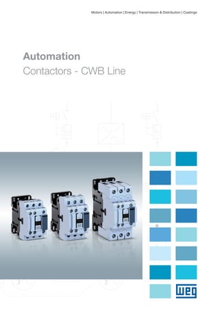
  • 1. Motors | Automation | Energy | Transmission & Distribution | Coatings Automation Contactors - CWB Line
  • 2.
  • 3. Summary Contactors - CWB Line Presentation 04 Selection Table 15 Application Forms 21 16Accessories 42Dimensions 34Technical Data
  • 4. Developed according to IEC/EN 60947 and UL 508 international standards, the WEG CWB line of contactors meets the requirements of a wide range of industrial applications worldwide. Characteristics JJ Currents from 9 to 80 A (AC-3); JJ Power supply from 24 V to 690 V ac/dc; JJ Low-consumption coils, 5.8 W at 24 V dc; JJ Compact, 18% smaller than the CWM line; JJ Built-in auxiliary contacts 1 NO and 1 NC; JJ Easy mounting of surge suppressor blocks; JJ Easy identification of the control voltage; JJ “Zero-width” mechanical interlock; COMPACT IN SIZE. GIANT IN TECHNOLOGY. JJ Easy-connection busbar for quick mounting of more compact reversing and star-delta starters; JJ Possibility to mount compact starters with MPW18, MPW40 and MPW80 manual motor protectors, and RW27-2D and RW67-5D thermal relays; JJ Choice of up to six auxiliary contacts; JJ Compatibility of accessories with the whole CWB line; JJ Fast mounting on DIN rail 35mm or with screw. Contactors - CWB Line4
  • 5. Suitable for different applications Benefits Modular and compact Internationally-recognized quality Simplified installation Energy saving Highly reliable Certifications 1) 1)1) Note: 1) Certification for CWB40-80 in progress. Russia MexicoSouth AfricaArgentinaCanada and USAEuropean Union Contactors - CWB Line 5
  • 6. Analysis of CWB electromagnetic system Process manufacturing simulation to ensure high quality of the injected parts Technology within your Reach The use of finite-element analysis and state-of-the-art modeling softwares for simulation of electromagnetic and electromechanical systems provide WEG CWB contactors with an improved project with reduced contact bouncing. The outcome reached by WEG’s RD team ensures a product with long mechanical and electrical lifespan in a reduced size and with lower energy consumption. The electric contacts of CWB contactors are manufactured with special silver alloys which ensure excellent electric conductibility and high contact reliability. During operation, the double-break contacts and arc chutes ensure fast arc quenching and provide high resistance against the wear effects of the electric arc and, consequently, a long electrical lifespan. Manufactured with the best raw materials and high-quality parts, the CWB line uses high-precision injection molds and metal stamping tools, ensuring very reliable products with the best cost-benefit on the market. Contactors - CWB Line6
  • 7. Energy Savings Low Consumption Coils The low-consumption coils of the CWB contactors enable safe operation with minimum energy consumption of up to 5.8 W in direct current, and up to 7.5 VA in alternating current. In addition to the energy saving, the low consumption of the contactor coils allows reducing the supply of control transformers. When well dimensioned and properly applied, the traditional electric motor starting methods, such as direct (reversing and non- reversing) and star-delta starters that use contactors, are the safest and the best cost-benefit options to start and protect low-voltage electric motors. Up to at least 55 kW, direct starters and star-delta starters that use contactors are still the best and most common starting method in all kinds of industry in the whole world. Even when electronic methods are used to start and control motors, such as frequency inverters and soft-starters, contactors are still necessary in combination with the electronic devices. Consequently, we can imagine the huge number of contactors installed and in operation, consuming energy in the whole world. Therefore, the CWB contactors were designed to operate safe and reliably with the lowest energy consumption. Coil Consumption DC Operated Contactor Standard contactor CWB Green Manufactured with nontoxic and low-impact materials, the CWB line of contactors is safe and sustainable, complying with the RoHS international requirements. DC Coils In addition to the low energy consumption, the DC coils enable direct control of the CWB contactors via PLC or digital outputs of devices such as frequency inverters or-starters without relay interfaces. Standard contactor Coil consumption DC Closed Contactor Energy saving 30% CWB www.weg.net Contactors - CWB Line 7
  • 8. Easy Panel Optimization 18% 45 mm 54 mm Allows + 1 Contactor Allows + 1 Contactor 55 mm 60 mm Compact Solution As they are compact, 45 mm wide available in up to 38 A (18.5 kW at 380 V AC-3 three-phase), and 54 mm wide available from 40 to 80 A (37 kW at 380 V AC-3 three-phase), the CWB contactors provide a general reduction in size of electrical panels in comparison to traditional solutions with contactors of the same specification. Built-In Auxiliary Contacts 1NO + 1NC The configuration of two built-in auxiliary contacts (1NO + 1NC) makes the application of CWB contactors more flexible in most automation systems, contributing to the optimization of internal space of electrical panels. More Simple and Organized Control Circuits In order to optimize the space in electrical panels even more, the CWB line of contactors has a front slot for passing control cables. That can reduce or eliminate the necessity of routing control cables through the side or front part of the contactors, providing a cleaner and more organized assembly of the control circuit. Standard ContactorsCWB Line Side by side mounting CWB38 Side by side mounting CWB80 www.weg.net Contactors - CWB Line8
  • 9. Easy Panel Optimization “Zero-Width” Mechanical Interlock For applications which require a mechanical interlock between contactors, WEG developed a new mechanical system that ensures compact and safe mounting without any tools. The new WEG mechanical interlocking system enables the mechanical interlock between the contactors of the CWB line without adding side space, and it is possible to mount reversing starters of up 80 A. 90 mm (2 x 45 mm) Simple and Compact Mounting of Surge Suppressor Blocks The coils of CWB contactors operate smoothly with a low level of disturbance in the control circuits. However, in order to reduce voltage surges due to the coil switching even further, WEG has developed surge suppressor blocks especially for the CWB line of contactors, which ensure limitation or even completely eliminate the undesired interferences that may be caused on opening the contactor coil. Surge suppressor blocks are easily mounted on CWB contactors without the need of any kind of tools and also without increasing volume. Contactor Coil Operated on AC or DC A wide range of voltages available in only two coil versions (one for AC and another for DC) for the whole line of contactors from 9 to 80 A. With easy replacement of the AC coil in currents from 9 to 80 A and DC coils in currents from 40 to 80 A with visual indication of the coil voltage. CWB9...38 A AC coil CWB9...80 A DC coil CWB40...80 A AC coil 108 mm (2 x 54 mm) www.weg.net Contactors - CWB Line 9
  • 10. Flexibility and Modularity in Assembly of Electric Panels Easy-Connection Busbars and Connectors The smooth integration between the CWB contactor line, overload relays and manual motor protectors enables simple and quick mounting of compact starters, besides protection sets for low-voltage electric motors with excellent cost effectiveness. The modularity and flexibility of the easy-connection busbars and connectors reduce the mounting time, also preventing possible errors. Available for the whole CWB line, the easy-connection system allows the mounting combined with WEG manual motor protectors and overload relays, forming compact and robust direct starters, reversing and non-reversing starters, in addition to star-delta starters. Contactors - CWB Line10
  • 11. Additional Contact Blocks Besides the 1NO + 1NC built-in auxiliary contacts, in order to meet the most complex control needs, WEG has also developed auxiliary high performance contact blocks which can be easily mounted on the front or side of CWB contactors, allowing the combination of up to six auxiliary contacts per contactor up to 80 A. An important characteristic of the side auxiliary contact blocks of the CWB line is the small dimension (only 9 mm wide) which meets the requirements of modularity, allowing more compact combinations of motor starters with motor protective circuit breakers when easy-connection busbars are used. Panel Assembly Flexibility CWB contactors can be easily assembled on panels using 35 mm DIN rails or screws because their oblong holes are compatible with the old and traditional lines of contactors on the market. Easy Access Power and Control Terminals All power terminals, auxiliary contacts and coils provide users with fast front access, facilitating installation, measurements and interventions for preventive and corrective maintenance of starters. Contactors - CWB Line 11
  • 12. Construction Characteristics Power contacts, easily identified Control terminals asymmetrically arranged in relation to the auxiliary contacts, preventing misconnections Auxiliary contacts incorporated, easily identified and separated from the power contacts, preventing misconnections Easy mounting of surge suppressor block without adding volume Mounting with screws Indelible labeling of the technical data to help the user use the product properly Opening for mechanical interlock DIN rail mounting www.weg.net Contactors - CWB Line12
  • 13. Applications The characteristics of the CWB contactors make them suitable for applications in many different segments. Paper Cellulose Wood Cement MiningChemical and Petrochemical Steel Oil Gas Refrigeration Sugar Alcohol Fans Machines and Processes in General Irrigation and Pumping Systems Civil Construction Load Lifting Automation www.weg.net Contactors - CWB Line 13
  • 14. Reliability and Safety Safety Against Accidental Contact All the power and control terminals of the CWB contactors have degree of protection that ensure total safety against accidental front contacts. Safety-Related Applications In automation systems of machines and equipment, it is common to use special contactors in combination with specific safety relays. The CWB line allows such combination due to the arrangement of the contacts, which comply with the requirements of IEC/EN 60947-4-1 Annex F (Mirror Contacts) and IEC/EN 60947-5-1 Annex L (Mechanically Linked Contacts and NR12 regulatory standard). IEC/EN 60947-5-1 Mechanically linked contacts IEC/EN 60947-4-1 Mirror contacts Contactors - CWB Line14
  • 15. Selection Table Ie max. (Ue ≤440 V) Ie = Ith (Ue ≤690 V) θ ≤55 °C Orientative rated operational power in AC-31) Three-phase motor - IV poles - 60 Hz - 1,800 rpm Auxiliary contacts per contactor Reference to fill in with the control voltage Weight2) kg AC-3 A AC-1 A 220 V 230 V kW / hp 380 V 400 V kW / hp 415 V 440 V kW / hp 500 V kW / hp 660 V 690 V kW / hp 4 3 NO 2 1 NC 9 25 2.2 / 3 3,7 / 5 4.5 / 6 5.5 / 7.5 5.5 / 7.5 1 1 CWB9-11-30♦ 0.372 12 25 3 / 4 5.5 / 7.5 5,5 / 7,5 7.5 / 10 7.5 / 10 1 1 CWB12-11-30♦ 0.372 18 32 4.5 / 6 7.5 / 10 9.2 / 12.5 9,2 / 12,5 11 / 15 1 1 CWB18-11-30♦ 0.372 25 40 5,5 / 7,5 11 / 15 11 / 15 15 / 20 15 / 20 1 1 CWB25-11-30♦ 0.408 32 50 7.5 / 10 15 / 20 15 / 20 18.5 / 25 18.5 / 25 1 1 CWB32-11-30♦ 0.408 38 50 9.2 / 12.5 18.5 / 25 18.5 / 25 18.5 / 25 18.5 / 25 1 1 CWB38-11-30♦ 0.408 40 60 11 / 15 18.5 / 25 22 / 30 22 / 30 30 / 40 1 1 CWB40-11-30♦ 0.91 50 90 15 / 20 22 / 30 30 / 40 30 / 40 30 / 40 1 1 CWB50-11-30♦ 0.91 65 110 18.5 / 25 30 / 40 37 / 50 37 / 50 37 / 50 1 1 CWB65-11-30♦ 0.91 80 110 22 / 30 37 / 50 45 / 60 55 / 75 45 / 60 1 1 CWB80-11-30♦ 0.91 Replace “♦” by the appropriate coil voltage code3). Alternating Current Direct Current Code D02 D07 D13 D23 D24 D25 D33 D34 D35 D36 D39 V (50/60 Hz) 24 48 110 220 230 240 380 400 415 440 480 Code C03 C07 C09 C12 C13 C15 V dc 24 48 60 110 125 220 Notes: 1) Orientative values. 2) Weight for contactors with control circuit in alternate current. For control circuit in direct current, add 0.121 kg to the alternating-current models. 3) Other voltages on request. Three-Pole from 9 A to 80 A (AC-3) NEW Contactors - CWB Line 15
  • 16. Accessory Overview 1 - Contactors CWB40...80 2 - Zero mechanical interlocking set (IM2) 3 - Side mounted auxiliary contact blocks BLRB 4 - Side mounted auxiliary contact blocks BLB 5 - Contactors CWB9...38 6 - Zero mechanical interlocking set (IM1) 1 3 4 5 2 9 10 6 1 www.weg.net Contactors - CWB Line16
  • 17. Accessory Overview 7 - Front mounted auxiliary contact blocks BFB 8 - Surge suppressor blocks 9 - Busbar for quick connections for reversing starters (EC-R-1) 10 - Busbar for quick connections for star-delta starters (EC-SD-1) 11 - Busbar for quick connections for reversing starters (EC-R-2) 12 - Busbar for quick connections for star-delta starters (EC-SD-2) 7 11 12 3 4 5 8 7 www.weg.net Contactors - CWB Line 17
  • 18. Front Mounted Auxiliary Contact Blocks Side Mounted Auxiliary Contact Block Illustrative picture For use with Max. nº of additional contacts / contactor Auxiliary contacts Reference Code Weight kgNO NC CWB9...38 CWB40...80 4 / CWB9...38 4 / CWB80...80 Auxiliary contact blocks according to IEC/EN 60947 1 1 BFB-111) 12123053 0.063 2 0 BFB-20 12122434 0 2 BFB-021) 12122946 2 2 BFB-221) 12123051 22) 22) BFB-22 EL2) 12771537 4 0 BFB-40 12122947 0 4 BFB-041) 12123048 3 1 BFB-311) 12123049 1 3 BFB-131) 12123052 Auxiliary contact blocks according to EN 50012 1 1 BFB-11 EN1) 12979242 0.063 2 0 BFB-20 EN 12979240 0 2 BFB-02 EN1) 12979241 2 2 BFB-22 EN1) 12979246 4 0 BFB-40 EN 12979243 0 4 BFB-04 EN1) 12979244 3 1 BFB-31 EN1) 12979245 1 3 BFB-13 EN1) 12979247 Illustrative picture For use with Max. nº of additional contacts / contactor Auxiliary contacts Reference Code Weight kgNO NC CWB9...38 CWB40...80 2 / CWB9...38 2 / CWB40...80 1 1 BLB-111) 12187899 0.034 2 0 BLB-20 12187334 0 2 BLB-021) 12187898 1 1 BLRB-111)3) 12230321 2 0 BLRB-203) 12230319 0 2 BLRB-021)3) 12230320 Plug-In Surge Suppressors Notes: 1) They comply with the requirements of IEC/EN 60947-4-1 about mirror contacts and the requirements of IEC/EN 60947-5-1 about mechanically linked contacts. 2) BFB-22-EL: besides the regular contacts NO and NC, there are two special contacts: early make and late break. 3) For side mounting of two side-auxiliary contact blocks on the same contactor side. 4) Contactors assembled with surge suppressor DIB will increase in 6 times the opening time. 5) Contactors assembled with surge suppressor DIZB will increase in 4 times the opening time. Accessories Illustrative picture For use with Voltage Diagram Reference Code Weight kg CWB9...38 CWB40...80 24...48 V 50/60 Hz RCBD53 12242511 0.008 50...127 V 50/60 Hz RCBD55 12242512 130...250 V 50/60 Hz RCBD63 12242513 12...48 V 50/60 Hz / 12...60 V dc VRBE49 12242514 50...127 V 50/60 Hz / 60...180 V dc VRBE34 12242515 130...250 V 50/60 Hz / 180...300 V dc VRBE50 12242516 277...380 V 50/60 Hz / 300...510 V dc VRBE41 12242517 400...510 V 50/60 Hz VRBD73 12242558 12...600 V dc DIBC334) 12242560 12...250 V dc DIZBC265) 12242561 www.weg.net Contactors - CWB Line18
  • 19. Accessories Mechanical Interlock Easy-Connection Setting of the Power Terminals for Reversing Starters Illustrative picture For use with Orientative rated operational power for reversing starters (AC-4 duty) for three-phase 4-pole motors - 60 Hz - 1,800 pm Reference Code Weight kg K1=K2 230 V kW / cv 400 V kW / cv CWB9 1.5 / 2.0 2.2 / 2.9 EC-R-1 12241229 0.042 CWB12 1.5 / 2.0 3.7 / 5.0 CWB18 2.2 / 2.9 4 / 5.4 CWB25 3 / 4.0 5.5 / 7.4 CWB32 4 / 5.4 7.5 / 10.1 CWB38 4 / 5.4 7.5 / 10.1 CWB40 4.5 / 6.0 9.2 / 12.3 EC-R-2 13619637 0.073 CWB50 5.5 / 7.4 11 / 14.7 CWB65 7.5 / 10.1 15 / 20.1 CWB80 11 / 14.7 18.5 / 24.8 Illustrative picture For use with Orientative rated operational power in AC-3 Three-phase motor - IV poles - 1,800 rpm Reference Code Weight kg K1=K2 K3 230 V kW / cv 400 V kW / cv CWB9 CWB9 4 / 5.4 7.5 / 10 EC-SD-1 12241230 0.046 CWB12 CWB9 5.5 / 7.5 11 / 15 CWB18 CWB12 9.2 / 12.5 15 / 20 CWB25 CWB18 11 / 15 22 / 30 CWB32 CWB18 15 / 20 - CWB38 CWB25 18.5 / 25 30 / 40 CWB50 CWB40 22 / 30 45 / 61 EC-SD-2 13619635 0.036CWB65 CWB40 30 / 40 55 / 75 CWB80 CWB50 45 / 61 75 / 102 Power Terminal Easy-Connection Set for Star-Delta Starters A1 A1 A2 A2 1L1 2T1 2T1 1L13L2 4T2 4T2 3L25L3 6T3 6T3 5L3 Electric diagram 1L1 1L1 1L13L2 3L2 3L25L3 5L3 5L3A1 A1 A2 A2 A2 2T12T1 2T14T24T2 4T26T36T3 6T3 A1 Electric diagram Illustrative picture For use with Description Reference Code Weight kg CWB9...38 Mounting set for interlocking two contactors with the same frame type. Fitting through snaps without tools. IM1 12244300 0.004 CWB40...80 IM2 13765620 www.weg.net Contactors - CWB Line 19
  • 20. Illustrative picture For use with Control type Reference to fill in with the control voltage Code Weight kg CWB9...38 AC BRB-38♦ On request 0.8 CWB40...80 AC BRB-80♦ On request 0.09 CWB40...80 DC BRB-80♦ On request 0.40 Spare Coils for Contactors1) Alternating Current Direct Current Code D02 D07 D13 D23 D24 D25 D33 D34 D35 D36 D39 V (50/60 Hz) 24 48 110 220 230 240 380 400 415 440 480 Code C03 C07 C09 C12 C13 C15 V dc 24 48 60 110 125 220 Accessories Replace “♦” by the appropriate coil voltage code. Note: 1) Spare coil in direct current (DC) only for CWB40...80 A. www.weg.net Contactors - CWB Line20
  • 21. Application Forms Easy Installation JJ Contactors, overload relays and manual motor protectors with a compact design up to 80 A (37 kW @ 380/415 V) JJ Easy-connection bars for direct on-line, reversing and star-delta starters, saving mounting time JJ Easy combination of all the starter parts JJ Contactors with built-in auxiliary contacts 1NO + 1NC Panel Optimization JJ 45 mm wide up to 38 A JJ 54 mm wide from 40 to 80 A JJ 9 mm wide side contact blocks JJ Compact starters JJ “Zero” mechanical interlock without adding side space JJ Simple and reliable parts Easy Operation JJ High performance and reliability for a wide range of applications JJ Energy savings JJ Without peak currents for contactors with DC coil JJ Built-in overload and short circuit protections (when MPW is used) Motor Starters With the CWB contactors, the MPW manual motor protectors and the RW overload relays, WEG offers a complete line of compact starters that stand out on the market. www.weg.net Contactors - CWB Line 21
  • 22. Direct On-Line Starters Motor current (A) AC-3 contactor Overload relay CWB + RW27-2D / CWB + RW67-5D Total weight (kg) Reference Maximum rated current AC-3 (A) Reference Current I adjustment range (A) Maximum fuse (gL/gG) (coordination type 1) (A) 0.28...0.4 CWB9-11-30♦ 9 RW27-2D3-D004 0.28...0.4 2 0.54 0.43...0.63 CWB9-11-30♦ 9 RW27-2D3-C063 0.43...0.63 2 0.54 0.56...0.8 CWB9-11-30♦ 9 RW27-2D3-D008 0.56...0.8 2 0.54 0.8...1.2 CWB9-11-30♦ 9 RW27-2D3-D012 0.8...1.2 4 0.54 1.2...1.8 CWB9-11-30♦ 9 RW27-2D3-D018 1.2...1.8 6 0.54 1.8...2.8 CWB9-11-30♦ 9 RW27-2D3-D028 1.8...2.8 6 0.54 2.8...4 CWB9-11-30♦ 9 RW27-2D3-U004 2.8...4 10 0.54 4...6.3 CWB9-11-30♦ 9 RW27-2D3-D063 4...6.3 16 0.54 5.6...8 CWB9-11-30♦ 9 RW27-2D3-U008 5.6...8 20 0.54 7...9 CWB9-11-30♦ 9 RW27-2D3-U010 7...10 25 0.54 8...12 CWB12-11-30♦ 12 RW27-2D3-D125 8...12.5 25 0.54 10...15 CWB18-11-30♦ 18 RW27-2D3-U015 10...15 35 0.54 11...17 CWB18-11-30♦ 18 RW27-2D3-U017 11...17 40 0.54 15...23 CWB25-11-30♦ 25 RW27-2D3-U023 15...23 50 0.57 22...32 CWB32-11-30♦ 32 RW27-2D3-U032 22...32 63 0.57 32...40 CWB38-11-30♦ 38 RW27-2D3-U040 32...40 90 0.57 25...40 CWB40-11-30♦ 40 RW67-5D3-U040 25...40 80 1.25 32...50 CWB50-11-30♦ 50 RW67-5D3-U050 32...50 100 1.25 40...57 CWB65-11-30♦ 65 RW67-5D3-U057 40...57 100 1.25 50...63 CWB65-11-30♦ 65 RW67-5D3-U063 50...63 100 1.25 57...70 CWB80-11-30♦ 80 RW67-5D3-U070 57...70 125 1.25 63...80 CWB80-11-30♦ 80 RW67-5D3-U080 63...80 125 1.25 CWB Contactor + RW27-2D/RW67-5D Thermal Overload Relay K1 1 2 1 3 5 2 4 3 4 6 5 6 FT1 Coil voltage codes C03 C07 C09 C12 C13 C15 V dc 24 48 60 110 125 220 Notes: Reference values valid for operating voltages up to 440 V, altitude up to 2,000 m, ambient temperature range from -20 °C to +55 °C, and maximum switching frequency up to 15 operations/hour. For other conditions, check the technical data of each part. JJ Remote load handling JJ Overload protection JJ Phase-loss sensitive JJ Trip class 10 JJ Temperature compensation JJ DIN rail mounting by fixing only one part JJ Manual/local or automatic reset Coil voltage codes D02 D07 D13 D15 D17 D77 D23 D24 D25 D33 D34 D35 D36 V (50/60 Hz) 24 48 110 120 127 208 220 230 240 380 400 415 440 To complete the reference code, replace “♦” by the appropriate coil voltage code www.weg.net Contactors - CWB Line22
  • 23. Direct On-Line Starters Motor current (A) AC-3 contactor Motor-protective circuit breaker Accessories Total weight (kg) Reference Maximum rated current AC-3 (A) Reference Current I adjustment range (A) Instantaneous magnetic trip (Im) (A) Connector 0.1...0.16 CWB9-11-30♦ 9 MPW18-3-C016 0.1...0.16 2.0 ECCMP-18B38 (CWB - AC Coil) 0.66 0.16...0.25 CWB9-11-30♦ 9 MPW18-3-C025 0.16...0.25 3.2 0.66 0.25...0.4 CWB9-11-30♦ 9 MPW18-3-D004 0.25...0.4 5.2 0.66 0.4...0.63 CWB9-11-30♦ 9 MPW18-3-C063 0.4...0.63 8.1 0.66 0.63...1 CWB9-11-30♦ 9 MPW18-3-U001 0.63...1 13 0.66 1...1.6 CWB9-11-30♦ 9 MPW18-3-D016 1...1.6 20.8 0.66 1.6...2.5 CWB9-11-30♦ 9 MPW18-3-D025 1.6...2.5 32.5 0.66 2.5...4 CWB9-11-30♦ 9 MPW18-3-U004 2.5...4 52 0.66 4...6.3 CWB9-11-30♦ 9 MPW18-3-D063 4...6.3 81.9 0.66 6.3...10 CWB12-11-30♦ 12 MPW18-3-U010 6.3...10 130 0.66 10...16 CWB18-11-30♦ 18 MPW18-3-U016 10...16 208 0.66 16...18 CWB18-11-30♦ 18 MPW18-3-U020 16...20 260 0.66 0.1...0.16 CWB9-11-30♦ 9 MPW40-3-C016 0.1...0.16 2 ECCMP-40B38 (CWB - AC Coil) ECCMP-40B38DC (CWB - DC Coil) 0.73 0.16...0.25 CWB9-11-30♦ 9 MPW40-3-C025 0.16...0.25 3.2 0.73 0.25...0.4 CWB9-11-30♦ 9 MPW40-3-D004 0.25...0.4 5.2 0.73 0.4...0.63 CWB9-11-30♦ 9 MPW40-3-C063 0.4...0.63 8.1 0.73 0.63...1 CWB9-11-30♦ 9 MPW40-3-U001 0.63...1 13 0.73 1...1.6 CWB9-11-30♦ 9 MPW40-3-D016 1...1.6 20.8 0.73 1.6...2.5 CWB9-11-30♦ 9 MPW40-3-D025 1.6...2.5 32.5 0.73 2.5...4 CWB9-11-30♦ 9 MPW40-3-U004 2.5...4 52 0.73 4...6.3 CWB9-11-30♦ 9 MPW40-3-D063 4...6.3 81.9 0.73 6.3...10 CWB12-11-30♦ 12 MPW40-3-U010 6.3...10 130 0.73 10...16 CWB18-11-30♦ 18 MPW40-3-U016 10...16 208 0.73 16...20 CWB25-11-30♦ 25 MPW40-3-U020 16...20 260 0.77 20...25 CWB25-11-30♦ 25 MPW40-3-U025 20...25 325 0.77 25...32 CWB32-11-30♦ 32 MPW40-3-U032 25...32 416 0.77 32...40 CWB38-11-30♦ 38 MPW40-3-U040 32...40 520 0.77 32...40 CWB40-11-30♦ 40 MPW80-3-U040 32...40 520 ECCMP-80B80 (CWB - AC and DC Coil) 2 45...50 CWB50-11-30♦ 50 MPW80-3-U050 45...50 650 2 55...65 CWB65-11-30♦ 65 MPW80-3-U065 55...65 845 2 65...80 CWB80-11-30♦ 80 MPW80-3-U080 65...80 1,040 2 CWB Contator + MPW18/MPW40/MPW80 Manual Motor Protectors 1 Q1 3 5 2 4 6 1 3 5 2 4 6 K1 Notes: Reference values valid for operating voltages up to 440 V, altitude up to 2,000 m, ambient temperature range from -20 °C to +55 °C, and maximum switching frequency up to 15 operations/hour. For other conditions, check the technical data of each part. Coil voltage codes D02 D07 D13 D15 D17 D77 D23 D24 D25 D33 D34 D35 D36 V (50/60 Hz) 24 48 110 120 127 208 220 230 240 380 400 415 440 Coil voltage codes C03 C07 C09 C12 C13 C15 V dc 24 48 60 110 125 220 To complete the reference code, replace “♦” by the appropriate coil voltage code JJ Remote load handling JJ Overload protection JJ Phase-loss sensitive JJ Temperature compensation JJ DIN rail mounting by fixing only one part JJ Manual/local reset JJ Isolation and disconnection functions JJ Protection against short circuit JJ High short-circuit interrupting capacity JJ Short circuit tripping device fixed at 13 x Iu www.weg.net Contactors - CWB Line 23
  • 24. Motor current (A) AC-3 contactor Overload relay Accessories CWB + RW27-2D / CWB + RW27-5D Total weight (kg) Reference Maximum rated current AC-3 (A) Reference Current I adjustment range (A) Mechanical interlock kit Easy-connection busbar Maximum fuse (gL/gG) (coordination type 1) (A) 0.28...0.4 CWB9-11-30♦ 9 RW27-2D3-D004 0.28...0.4 IM1 EC-R1 2 0.91 0.43...0.63 CWB9-11-30♦ 9 RW27-2D3-C063 0.43...0.63 2 0.91 0.56...0.8 CWB9-11-30♦ 9 RW27-2D3-D008 0.56...0.8 2 0.91 0.8...1.2 CWB9-11-30♦ 9 RW27-2D3-D012 0.8...1.2 4 0.91 1.2...1.8 CWB9-11-30♦ 9 RW27-2D3-D018 1.2...1.8 6 0.91 1.8...2.8 CWB9-11-30♦ 9 RW27-2D3-D028 1.8...2.8 6 0.91 2.8...4 CWB9-11-30♦ 9 RW27-2D3-U004 2.8...4 10 0.91 4...6.3 CWB9-11-30♦ 9 RW27-2D3-D063 4...6.3 16 0.91 5.6...8 CWB9-11-30♦ 9 RW27-2D3-U008 5.6...8 20 0.91 7...9 CWB12-11-30♦ 12 RW27-2D3-U010 7...10 25 0.91 8...12 CWB25-11-30♦ 25 RW27-2D3-D125 8...12.5 25 0.98 10...15 CWB25-11-30♦ 25 RW27-2D3-U015 10...15 35 0.98 11...17 CWB25-11-30♦ 25 RW27-2D3-U017 11...17 40 0.98 15...23 CWB25-11-30♦ 25 RW27-2D3-U023 15...23 50 0.98 22...32 CWB32-11-30♦ 32 RW27-2D3-U032 22...32 63 0.98 32...38 CWB38-11-30♦ 38 RW27-2D3-U040 32...40 90 0.98 25...40 CWB40-11-30♦ 40 RW67-5D-U040 25...40 IM2 EC-R2 80 2.3 32...50 CWB50-11-30♦ 50 RW67-5D-U050 32...50 100 2.3 40...57 CWB65-11-30♦ 65 RW67-5D-U057 40...57 100 2.3 50...63 CWB65-11-30♦ 65 RW67-5D-U063 50...63 100 2.3 57...70 CWB80-11-30♦ 80 RW67-5D-U070 57...70 125 2.3 63...80 CWB80-11-30♦ 80 RW67-5D-U080 63...80 125 2.3 CWB Contactor + RW27-2D/RW67-5D Thermal Overload Relay Reversing Starters K1 K2IM11 2 4 6 2 FT1 4 6 2 4 6 3 5 1 3 5 1 3 5 JJ Remote load handling JJ Overload protection JJ Phase-loss sensitive JJ Trip class 10 JJ Temperature compensation JJ DIN rail mounting by fixing the contactors JJ Manual/local or automatic reset Notes: Reference values valid for operating voltages up to 440 V, altitude up to 2,000 m, ambient temperature range from -20 °C to +55 °C, and maximum switching frequency up to 15 operations/hour. For other conditions, check the technical data of each part. Coil voltage codes D02 D07 D13 D15 D17 D77 D23 D24 D25 D33 D34 D35 D36 V (50/60 Hz) 24 48 110 120 127 208 220 230 240 380 400 415 440 Coil voltage codes C03 C07 C09 C12 C13 C15 V dc 24 48 60 110 125 220 To complete the reference code, replace “♦” by the appropriate coil voltage code IM1/IM2 www.weg.net Contactors - CWB Line24
  • 25. Reversing Starters Motor current (A) AC-3 contactor Motor-protective circuit breaker Accessories Total weight (kg)Reference Maximum rated current AC-3 (A) Reference Current I adjustment range (A) Instantaneous magnetic trip (Im) (A) Connector Easy-connection busbar Mechanical interlock kit 0.1...0.16 CWB9-11-30♦ 9 MPW18-3-C016 0.1...0.16 2.0 ECCMP-18B38 (CWB - AC Coil) EC-R1 IM1 1 0.16...0.25 CWB9-11-30♦ 9 MPW18-3-C025 0.16...0.25 3.2 1 0.25...0.4 CWB9-11-30♦ 9 MPW18-3-D004 0.25...0.4 5.2 1 0.4...0.63 CWB9-11-30♦ 9 MPW18-3-C063 0.4...0.63 8.1 1 0.63...1 CWB9-11-30♦ 9 MPW18-3-U001 0.63...1 13 1 1...1.6 CWB9-11-30♦ 9 MPW18-3-D016 1...1.6 20.8 1 1.6...2.5 CWB9-11-30♦ 9 MPW18-3-D025 1.6...2.5 32.5 1 2.5...4 CWB9-11-30♦ 9 MPW18-3-U004 2.5...4 52 1 4...6.3 CWB9-11-30♦ 9 MPW18-3-D063 4...6.3 81.9 1 6.3...10 CWB12-11-30♦ 12 MPW18-3-U010 6.3...10 130 1 10...16 CWB18-11-30♦ 18 MPW18-3-U016 10...16 208 1 16...20 CWB25-11-30♦ 25 MPW18-3-U020 16...20 260 1.1 0.1...0.16 CWB9-11-30♦ 9 MPW40-3-C016 0.1...0.16 2 ECCMP-40B38 (CWB - AC Coil) ECCMP-40B38DC (CWB - DC Coil) EC-R1 IM1 1.1 0.16...0.25 CWB9-11-30♦ 9 MPW40-3-C025 0.16...0.25 3.2 1.1 0.25...0.4 CWB9-11-30♦ 9 MPW40-3-D004 0.25...0.4 5.2 1.1 0.4...0.63 CWB9-11-30♦ 9 MPW40-3-C063 0.4...0.63 8.1 1.1 0.63...1 CWB9-11-30♦ 9 MPW40-3-U001 0.63...1 13 1.1 1...1.6 CWB9-11-30♦ 9 MPW40-3-D016 1...1.6 20.8 1.1 1.6...2.5 CWB9-11-30♦ 9 MPW40-3-D025 1.6...2.5 32.5 1.1 2.5...4 CWB9-11-30♦ 9 MPW40-3-U004 2.5...4 52 1.1 20...25 CWB25-11-30♦ 25 MPW40-3-U025 20...25 325 1.18 25...32 CWB32-11-30♦ 32 MPW40-3-U032 25...32 416 1.18 32...40 CWB38-11-30♦ 38 MPW40-3-U040 32...40 520 1.18 32...40 CWB40-11-30♦ 40 MPW80-3-U040 32...40 520 ECCMP-80B80 (CWB - - AC and DC Coil) EC-R2 IM2 2.9 40...50 CWB50-11-30♦ 50 MPW80-3-U050 40...50 650 2.9 50...65 CWB65-11-30♦ 65 MPW80-3-U065 50...65 845 2.9 65...80 CWB80-11-30♦ 80 MPW80-3-U080 65...80 1,040 2.9 CWB Contator + MPW18/MPW40/MPW80 Manual Motor Protectors K1 1 Q1 3 5 1 3 5 1 3 5 2 4 6 2 4 6 K2 2 4 6 IM1 JJ Remote load handling JJ Overload protection JJ Phase-loss sensitive JJ Temperature compensation JJ DIN rail mounting by fixing only one part1) JJ Manual/local or automatic reset JJ Isolation and disconnection functions JJ Protection against short circuit JJ High short-circuit interrupting capacity JJ Short circuit tripping device fixed at 13 x Iu Notes: Reference values valid for operating voltages up to 440 V, altitude up to 2,000 m, ambient temperature range from -20 °C to +55 °C, and maximum switching frequency up to 15 operations/hour. For other conditions, check the technical data of each part. Note: 1) For reversing or star-delta starters, mount the contactors with screws. Coil voltage codes D02 D07 D13 D15 D17 D77 D23 D24 D25 D33 D34 D35 D36 V (50/60 Hz) 24 48 110 120 127 208 220 230 240 380 400 415 440 Coil voltage codes C03 C07 C09 C12 C13 C15 V dc 24 48 60 110 125 220 To complete the reference code, replace “♦” by the appropriate coil voltage code IM1/IM2 www.weg.net Contactors - CWB Line 25
  • 26. Motor current (A) AC-3 contactor Overload relay Accessories CWB + RW27-2D / CWB + RW27-5D Total weight (kg)Contactor Δ (K1 and K2) Contactor Y (K3) Reference Current I adjustment range (A) Mechanical interlock kit Easy-connection busbar Timing relay Y-Δ Maximum fuse (gL/gG) Coordination type 1 0.5...0.7 CWB9-11-30♦ CWB9-11-30♦ RW27-2D3-D004 0.28...0.4 IM1 EC-SD1 RTW17-G02 2 1.3 0.7...1.1 CWB9-11-30♦ CWB9-11-30♦ RW27-2D3-C063 0.4...0.63 2 1.3 1.1...1.4 CWB9-11-30♦ CWB9-11-30♦ RW27-2D3-D008 0.63...0.8 2 1.3 1.4...2.1 CWB9-11-30♦ CWB9-11-30♦ RW27-2D3-D012 0.8...1.2 4 1.3 2.1...3.1 CWB9-11-30♦ CWB9-11-30♦ RW27-2D3-D018 1.2...1.8 6 1.3 3.1...4.8 CWB9-11-30♦ CWB9-11-30♦ RW27-2D3-D028 1.8...2.8 6 1.3 4.8...6.9 CWB9-11-30♦ CWB9-11-30♦ RW27-2D3-U004 2.8...4 10 1.3 6.9...10.9 CWB9-11-30♦ CWB9-11-30♦ RW27-2D3-D063 4...6.3 16 1.3 9.6...13.8 CWB9-11-30♦ CWB9-11-30♦ RW27-2D3-U008 5.6...8 20 1.3 12.1...17.2 CWB12-11-30♦ CWB9-11-30♦ RW27-2D3-U010 7...10 25 1.3 13.8...21.6 CWB18-11-30♦ CWB9-11-30♦ RW27-2D3-D125 8...12.5 25 1.3 17.2...25.9 CWB18-11-30♦ CWB9-11-30♦ RW27-2D3-U015 10...15 35 1.3 19...29.3 CWB18-11-30♦ CWB12-11-30♦ RW27-2D3-U017 11...17 40 1.3 25.9...39.7 CWB25-11-30♦ CWB18-11-30♦ RW27-2D3-U023 15...23 50 1.35 37.9...55.2 CWB32-11-30♦ CWB25-11-30♦ RW27-2D3-U032 22...32 63 1.4 43.1...65.5 CWB38-11-30♦ CWB25-11-30♦ RW27-2D3-U040 32...40 90 1.4 43.1...69 CWB40-11-30♦ CWB40-11-30♦ RW67- 5D -U040 25...40 IM2 EC-SD2 80 3.1 55.2...86.2 CWB50-11-30♦ CWB40-11-30♦ RW67- 5D -U050 32...50 100 3.1 69...98.3 CWB65-11-30♦ CWB40-11-30♦ RW67- 5D -U057 40...57 100 3.1 86.2...108.6 CWB65-11-30♦ CWB40-11-30♦ RW67- 5D -U063 50...63 100 3.1 98.3...120.7 CWB80-11-30♦ CWB40-11-30♦ RW67- 5D -U070 57...70 125 3.1 108.6...137.9 CWB80-11-30♦ CWB40-11-30♦ RW67- 5D -U080 63...80 125 3.1 CWB Contactor + RW27-2D/RW67-5D Thermal Overload Relay Star-Delta Starters K1 IM11 3 5 1 3 5 2 4 6 K2 K3 2 4 6 1 3 5 2 4 6 2 FT1 4 6 1 3 5 JJ Remote load handling JJ Overload protection JJ Phase-loss sensitive JJ Trip class 10 JJ Temperature compensation JJ DIN rail mounting by fixing the contactors JJ Manual/local or automatic reset Notes: Reference values valid for operating voltages up to 440 V, altitude up to 2,000 m, ambient temperature range from -20 °C to +55 °C, and maximum switching frequency up to 15 operations/hour. For other conditions, check the technical data of each part. The electronic timer is not shown in the figure. Coil voltage codes D02 D07 D13 D15 D17 D77 D23 D24 D25 D33 D34 D35 D36 V (50/60 Hz) 24 48 110 120 127 208 220 230 240 380 400 415 440 Coil voltage codes C03 C07 C09 C12 C13 C15 V dc 24 48 60 110 125 220 To complete the reference code, replace “♦” by the appropriate coil voltage code IM1/IM2 www.weg.net Contactors - CWB Line26
  • 27. Star-Delta Starters Motor current (A) AC-3 contactor Motor-protective circuit breaker Accessories Total weight (kg)Contactor Δ (K1 and K2) Contactor Y (K3) Reference Current I ad- justment range (A) Instantaneous magnetic trip Im (A) Connector Mechanical interlock kit Easy- connection busbar Timing relay Y-Δ 0.1...0.16 CWB9-11-30♦ CWB9-11-30♦ MPW18-3-C016 0.1...0.16 2.0 ECCMP-18B38 (CWB - AC Coil) IM1 EC-SD1 RTW17-G02 1.4 0.16...0.25 CWB9-11-30♦ CWB9-11-30♦ MPW18-3-C025 0.16...0.25 3.2 1.4 0.25...0.4 CWB9-11-30♦ CWB9-11-30♦ MPW18-3-D004 0.25...0.4 5.2 1.4 0.4...0.63 CWB9-11-30♦ CWB9-11-30♦ MPW18-3-C063 0.4...0.63 8.1 1.4 0.63...1 CWB9-11-30♦ CWB9-11-30♦ MPW18-3-U001 0.63...1 13 1.4 1...1.6 CWB9-11-30♦ CWB9-11-30♦ MPW18-3-D016 1...1.6 20.8 1.4 1.6...2.5 CWB9-11-30♦ CWB9-11-30♦ MPW18-3-D025 1.6...2.5 32.5 1.4 2.5...4 CWB9-11-30♦ CWB9-11-30♦ MPW18-3-U004 2.5...4 52 1.4 4...6.3 CWB9-11-30♦ CWB9-11-30♦ MPW18-3-D063 4...6.3 81.9 1.4 6.3...10 CWB9-11-30♦ CWB9-11-30♦ MPW18-3-U010 6.3...10 130 1.4 10...16 CWB12-11-30♦ CWB9-11-30♦ MPW18-3-U016 10...16 208 1.4 12...18 CWB12-11-30♦ CWB9-11-30♦ MPW18-3-U018 12...18 260 1.4 CWB Contator + MPW18 Manual Motor Protectors JJ Remote load handling JJ Protection against overload JJ Phase-loss sensitive JJ Temperature compensation JJ DIN rail mounting by fixing only one part1) JJ Manual/local reset JJ Isolation and disconnection functions JJ Protection against short circuit JJ High short circuit interrupting capacity JJ Short circuit tripping device fixed at 13 x Iu Notes: Reference values valid for operating voltages up to 440 V, altitude up to 2,000 m, ambient temperature range from -20 °C to +55 °C, and maximum switching frequency up to 15 operations/hour. For other conditions, check the technical data of each part. The electronic timer is not shown in the figure. Note: 1) For reversing or star-delta starters, mount the contactors with screws. Coil voltage codes D02 D07 D13 D15 D17 D77 D23 D24 D25 D33 D34 D35 D36 V (50/60 Hz) 24 48 110 120 127 208 220 230 240 380 400 415 440 Coil voltage codes C03 C07 C09 C12 C13 C15 V dc 24 48 60 110 125 220 To complete the reference code, replace “♦” by the appropriate coil voltage code K1 IM1 1 Q1 3 5 1 3 5 1 3 5 2 4 6 2 4 6 K2 K3 2 4 6 1 3 5 2 4 6 IM1/IM2 www.weg.net Contactors - CWB Line 27
  • 28. Motor current (A) AC-3 contactor Motor-protective circuit breaker Accessories Total weight (kg)Contactor Δ (K1 and K2) Contactor Y (K3) Reference Current I adjustment range (A) Instantaneous magnetic trip Im (A) Connector Mechanical interlock kit Easy- connection busbar Timing relay Y-Δ 0.1...0.16 CWB9-11-30♦ CWB9-11-30♦ MPW40-3-C016 0.1...0.16 2.0 ECCMP-40B38 (CWB - AC Coil) ECCMP- 40B38DC (CWB - DC Coil) IM1 EC-SD1 RTW17-G02 1.48 0.16...0.25 CWB9-11-30♦ CWB9-11-30♦ MPW40-3-C025 0.16...0.25 3.2 1.48 0.25...0.4 CWB9-11-30♦ CWB9-11-30♦ MPW40-3-D004 0.25...0.4 5.2 1.48 0.4...0.63 CWB9-11-30♦ CWB9-11-30♦ MPW40-3-C063 0.4...0.63 8.1 1.48 0.63...1 CWB9-11-30♦ CWB9-11-30♦ MPW40-3-U001 0.63...1 13 1.48 1...1.6 CWB9-11-30♦ CWB9-11-30♦ MPW40-3-D016 1...1.6 20.8 1.48 1.6...2.5 CWB9-11-30♦ CWB9-11-30♦ MPW40-3-D025 1.6...2.5 32.5 1.48 2.5...4 CWB9-11-30♦ CWB9-11-30♦ MPW40-3-U004 2.5...4 52 1.48 4...6.3 CWB9-11-30♦ CWB9-11-30♦ MPW40-3-D063 4...6.3 81.9 1.48 6.3...10 CWB9-11-30♦ CWB9-11-30♦ MPW40-3-U010 6.3...10 130 1.48 10...16 CWB12-11-30♦ CWB9-11-30♦ MPW40-3-U016 10...16 208 1.48 16...20 CWB12-11-30♦ CWB9-11-30♦ MPW40-3-U020 16...20 260 1.48 20...25 CWB18-11-30♦ CWB9-11-30♦ MPW40-3-U025 20...25 325 1.48 25...32 CWB25-11-30♦ CWB12-11-30♦ MPW40-3-U032 25...32 416 1.55 32...40 CWB25-11-30♦ CWB18-11-30♦ MPW40-3-U040 32...40 520 1.55 32...40 CWB40-11-30♦ CWB40-11-30♦ MPW80-3-U040 32...40 520 ECCMP-80B80 (CWB - AC and DC Coil) IM2 EC-SD2 3.83 40...50 CWB50-11-30♦ CWB40-11-30♦ MPW80-3-U050 40...50 650 3.83 50...65 CWB65-11-30♦ CWB40-11-30♦ MPW80-3-U065 50...65 845 3.83 65...80 CWB80-11-30♦ CWB40-11-30♦ MPW80-3-U080 65...80 1,040 3.83 CWB Contator + MPW40/MPW80 Manual Motor Protectors Star-Delta Starters K1 IM1/IM2 1 Q1 3 5 1 3 5 1 3 5 2 4 6 2 4 6 K2 K3 2 4 6 1 3 5 2 4 6 JJ Remote load handling JJ Protection against overload JJ Phase-loss sensitive JJ Temperature compensation JJ DIN rail mounting by fixing only one part1) JJ Manual/local or automatic reset JJ Isolation and disconnection functions JJ Protection against short circuit JJ High short circuit interrupting capacity JJ Short circuit tripping device fixed at 13 x Iu Notes: Reference values valid for operating voltages up to 440 V, altitude up to 2,000 m, ambient temperature range from -20 °C to +55 °C, and maximum switching frequency up to 15 operations/hour. For other conditions, check the technical data of each part. The electronic timer is not shown in the figure. Note: 1) For reversing or star-delta starters, mount the contactors with screws. Coil voltage codes D02 D07 D13 D15 D17 D77 D23 D24 D25 D33 D34 D35 D36 V (50/60 Hz) 24 48 110 120 127 208 220 230 240 380 400 415 440 Coil voltage codes C03 C07 C09 C12 C13 C15 V dc 24 48 60 110 125 220 To complete the reference code, replace “♦” by the appropriate coil voltage code www.weg.net Contactors - CWB Line28
  • 29. Contactors for Lighting Circuits JJ Single-Phase Circuit Total number of light bulbs shown in the next figure. JJ Three-Phase Circuit Connected in Delta Total number of light bulbs shown in the next figure, multiplied by 1.73 and distributed in three equal quantities. JJ Three-Phase Circuit Connected in Delta Total number of light bulbs shown in the next figure, multiplied by 3 and distributed in three equal quantities. Diagrams Single-phase circuit Three-phase circuit connected in delta Three-phase circuit connected in star Most Common Characteristics of the Illumination Systems JJ Incandescent Light Bulbs High inrush current (≈15 x In). Despite the short duration, it must be taken into account so that this current will not be greater than the making capacity of the contactor. Power factor is always 1. JJ Fluorescent Lamps Current slightly above the rated inrush current. Power factor is normally 0.5, and it can be improved up to 0.9 by using capacitors. In some cases, the connection of capacitors must be taken into consideration, as they may cause some damages to smaller contactors. JJ High-Pressure Mercury-Vapor and Metal-Halide Lamps Inrush current varies according to the lamp type, around 1.6....2 x In and it remains for 3 to 5 minutes. The power factor is around 0.6 and may be improved up to 1 by using capacitors. In some cases, the connection of capacitors must be taken into consideration, as they may cause some damages to smaller contactors. JJ High-Pressure Sodium Lamps Inrush current varies according to the lamp type, around 1.3....1.6 x In e se mantém por 3 a 5 minutos. and it remains for 3 to 5 minutes. The power factor is around 0.45 and may be improved up to 1 using capacitors. In some cases, the connection of capacitors must be taken into consideration, as they may cause some damages to smaller contactors. L1 L2 L3 220 V220 V NL1 L2 L3 220 V220 V L1 L3(N) 220 V www.weg.net Contactors - CWB Line 29
  • 30. Maximum number of lamps per phase at 220 V Lamp type W A2) µF CWB9 CWB12 CWB18 CWB25 CWB32 CWB38 CWB40 CWB50 CWB65 CWB80 Incandescent and halogen 60 0.27 - 56 56 67 101 118 135 148 185 241 296 100 0.45 - 33 33 40 60 71 81 89 111 144 178 150 0.68 - 22 22 26 40 47 53 59 74 96 118 200 0.91 - 16 16 19 29 35 40 44 55 71 88 300 1.4 - 10 10 12 19 22 26 29 36 46 54 500 2.3 - 6 6 7 11 13 15 17 22 28 35 750 3.4 - 4 4 5 8 9 10 12 15 19 24 1,000 4.6 - 3 3 3 5 6 7 9 11 14 17 AC-5b ¹) (A) 15 15 18 28 32 36 40 50 65 80 Fluorescent lamps with electronic starter Single arrangement Without compensation 20 0.39 - 41 41 53 66 89 112 115 144 187 230 40 0.45 - 35 35 46 57 77 97 100 124 162 199 65 0.7 - 22 22 30 37 50 62 64 80 104 128 80 0.8 - 20 20 26 32 43 55 56 70 91 112 110 1.2 - 13 13 17 21 29 36 37 47 61 75 With paralel compensation 20 0.17 5 94 94 123 152 205 258 264 329 428 527 40 0.26 5 61 61 80 100 134 169 172 215 280 345 65 0.42 7 38 38 50 61 83 104 107 133 173 213 80 0.52 7 30 30 40 50 67 84 86 108 140 172 110 0.72 16 22 22 29 36 48 61 62 78 101 124 Dual mounting Without compensation 2x20 2x0.22 - 2x36 2x36 2x46 2x58 2x78 2x100 2x10² 2x127 2x165 2x204 2x40 2x0.41 - 2x18 2x18 2x24 2x30 2x42 2x52 2x55 2x68 2x89 2x10⁹ 2x65 2x0.67 - 2x10 2x10 2x14 2x18 2x26 2x32 2x33 2x42 2x54 2x67 2x80 2x0.82 - 2x8 2x8 2x12 2x14 2x20 2x26 2x27 2x34 2x44 2x55 2x110 2x1.10 - 2x6 2x6 2x8 2x10 2x14 2x18 2x20 2x25 2x33 2x41 With series compensation 2x20 2x0.13 - 2x60 2x60 2x80 2x100 2x134 2x168 2x172 2x215 2x280 2x345 2x40 2x0.24 - 2x32 2x32 2x42 2x54 2x72 2x90 2x93 2x117 2x152 2x187 2x65 2x0.39 - 2x20 2x20 2x26 2x32 2x44 2x56 2x57 2x72 2x93 2x115 2x80 2x0.48 - 2x16 2x16 2x20 2x26 2x36 2x44 2x47 2x58 2x76 2x93 2x110 2x0.65 - 2x12 2x12 2x16 2x20 2x26 2x32 2x34 2x43 2x56 2x69 Fluorescent lamps without electronic starter Single mounting Without compensation 20 0.43 - 37 37 48 60 97 102 104 130 169 208 40 0.55 - 29 29 38 47 63 80 81 102 132 163 65 0.8 - 20 20 26 32 43 55 56 70 91 112 80 0.95 - 16 16 22 27 36 46 47 59 77 94 110 1.4 - 11 11 15 18 25 31 32 40 52 64 With paralel compensation 20 0.19 5 84 84 110 136 184 231 236 295 383 472 40 0.29 5 55 55 72 89 101 151 154 193 251 309 65 0.46 7 34 34 45 56 76 95 97 122 158 195 80 0.57 7 28 28 36 45 61 77 79 98 128 157 110 0.79 16 20 20 26 32 44 55 57 71 92 113 Dual mounting Without compensation 2x20 2x0.25 - 2x32 2x32 2x42 2x52 2x70 2x88 2x90 2x112 2x146 2x179 2x40 2x0.47 - 2x16 2x16 2x22 2x26 2x36 2x46 2x48 2x60 2x77 2x95 2x65 2x0.76 - 2x10 2x10 2x12 2x16 2x22 2x28 2x29 2x37 2x48 2x59 2x80 2x0.93 - 2x8 2x8 2x10 2x12 2x18 2x22 2x24 2x30 2x39 2x48 2x110 2x1.3 - 2x6 2x6 2x8 2x10 2x12 2x16 2x17 2x22 2x28 2x34 With paralel compensation 2x20 2x0.14 - 2x56 2x56 2x74 2x92 2x124 2x156 2x16 2x200 2x260 2x320 2x40 2x0.26 - 2x30 2x30 2x40 2x50 2x66 2x84 2x86 2x10⁸ 2x140 2x172 2x65 2x0.43 - 2x18 2x18 2x24 2x30 2x40 2x50 2x52 2x65 2x85 2x10⁴ 2x80 2x0.53 - 2x14 2x14 2x18 2x24 2x32 2x40 2x42 2x53 2x69 2x51 2x110 2x0.72 - 2x10 2x10 2x14 2x18 2x24 2x30 2x31 2x39 2x51 2x62 Notes: 1) Indicative values - It’s highly recommended to take into consideration the values of making capacity and rated AC-1 current when dimensioning the contactor for AC-5b utilization category (switching of incandescent lamps). 2) Rated current for each lamp at rated voltage. Contactors for Lighting Circuits www.weg.net Contactors - CWB Line30
  • 31. Maximum number of lamps per phase at 220 V Lamp type W A µF CWB9 CWB12 CWB18 CWB25 CWB32 CWB38 CWB40 CWB50 CWB65 CWB80 Low pressure sodium vapor Without compensation 35 1.2 - 10 10 12 15 21 27 37 46 60 73 55 1.6 - 7 7 9 11 16 20 28 34 45 55 90 2.4 - 5 5 6 7 10 13 18 23 30 37 135 3.1 - 3 3 4 6 8 10 14 18 23 28 150 3.2 - 3 3 4 5 8 10 14 17 22 28 180 3.3 - 3 3 4 5 7 10 14 17 22 27 200 3.4 - 3 3 4 5 7 9 13 16 21 26 With paralel compensation 35 0.3 17 40 40 50 63 86 110 149 187 243 299 55 0.4 17 30 30 37 47 65 82 112 140 182 224 90 0.6 25 - - 25 31 43 55 75 93 121 149 135 0.9 36 - - - 21 28 36 50 62 81 100 150 1 36 - - - 19 26 33 45 56 73 90 180 1.2 36 - - - 15 21 27 200 1.3 36 - - - 14 20 25 High pressure sodium vapor Without compensation 150 1.9 - 6 6 7 10 13 17 21 26 34 42 250 3.2 - 3 3 4 5 8 10 13 16 20 25 400 5 - 2 2 3 3 5 6 8 10 13 16 700 8.8 - 1 1 1 2 2 3 5 6 7 9 1,000 12.4 - - - 1 1 2 2 3 4 5 6 With paralel compensation 150 0.84 20 - - 17 22 30 39 48 60 77 95 250 1.4 32 - - - 13 18 23 29 36 46 57 400 2.2 48 - - - 8 11 15 18 23 30 36 700 3.9 96 - - - - 6 8 10 13 17 21 1,000 5.5 120 - - - - - 6 7 9 12 15 High pressure mercury vapor Without compensation 50 0.54 - 22 22 27 35 48 61 74 93 120 148 80 0.81 - 14 14 18 23 32 40 49 62 80 99 125 1.2 - 9 9 12 15 21 27 33 42 54 67 250 2.3 - 5 5 6 8 11 14 17 22 28 35 400 4.1 - 2 2 3 4 6 8 10 12 16 20 700 6.8 - 1 1 2 2 3 4 6 7 10 12 1,000 9.9 - 1 1 1 1 2 3 4 5 7 8 With paralel compensation 50 0.3 10 40 40 50 63 86 110 133 167 217 267 80 0.45 10 26 26 33 42 57 73 89 111 144 178 125 0.67 10 17 17 22 28 38 49 60 75 97 119 250 1.3 18 9 9 11 14 20 25 31 38 50 62 400 2.3 25 - - 6 8 11 14 17 22 28 35 700 3.8 40 - - - 5 6 8 1,000 5.5 60 - - - 3 4 6 Metal iodide Without compensation 250 2.5 - 4 4 6 7 10 12 16 20 26 32 400 3.6 - 3 3 4 5 7 8 11 14 18 22 1,000 9.5 - 1 1 1 2 2 3 4 5 7 8 2,000 20 - - - - - 1 1 2 3 3 4 With paralel compensation 250 1.4 32 - - - 13 18 21 29 36 46 57 400 2 32 - - - 9 13 15 20 25 33 40 1,000 5.3 64 - - - - 4 6 8 9 12 15 2,000 11.2 140 - - - - - - 4 4 6 7 Contactors for Lighting Circuits www.weg.net Contactors - CWB Line 31
  • 32. Contactors for DC Switching Utilization Category DC-1 (L/R 1ms) Reference code CWB9 CWB12 CWB18 CWB25 CWB32 CWB38 CWB40 CWB50 CWB65 CWB80 Ue Poles in series Rated operational current Ie (A) ≤24 V 1 18 18 18 25 32 40 40 50 65 65 2 25 25 32 45 60 60 40 50 65 65 3 25 25 32 45 60 60 40 50 65 65 ≤48 V 1 15 15 15 20 25 35 40 50 65 65 2 25 25 32 45 60 60 40 50 65 65 3 25 25 32 45 60 60 40 50 65 65 ≤60 V 1 12 12 12 18 18 32 40 50 65 65 2 25 25 32 45 60 60 40 50 65 65 3 25 25 32 45 60 60 40 50 65 65 ≤125 V 1 6 6 6 8 8 8 10 10 10 10 2 18 18 18 25 45 45 40 50 60 60 3 25 25 25 32 60 60 40 60 65 65 ≤220 V 1 0.8 0.8 0.8 0.8 1 1 2 2 2 2 2 7.5 7.5 7.5 8 8 8 10 10 10 10 3 25 25 25 32 50 50 40 50 60 60 ≤440 V 1 0.4 0.4 0.4 0.4 0.5 0.5 1 1 1 1 2 0.8 0.8 0.8 0.8 1 1 2 2 2 2 3 8 8 8 10 10 10 10 10 10 10 ≤600 V 1 - - - - - - - - - - 2 0.4 0.4 0.4 0.4 0.5 0.5 1 1 1 1 3 4 4 4 5 5 5 2 2 2 2 Utilization Category DC-3 (L/R 2.5ms) Reference code CWB9 CWB12 CWB18 CWB25 CWB32 CWB38 CWB40 CWB50 CWB65 CWB80 Ue Poles in series Rated operational current Ie (A) ≤24 V 1 12 12 12 18 25 32 36 45 55 55 2 18 18 18 25 40 40 36 45 55 55 3 18 18 18 25 40 40 36 45 55 55 ≤48 V 1 9 9 9 12 18 20 36 45 55 55 2 18 18 18 25 40 40 36 45 55 55 3 18 18 18 25 40 40 36 45 55 55 ≤60 V 1 7.5 7.5 7.5 10 15 15 36 45 55 55 2 18 18 18 25 40 40 36 45 55 55 3 18 18 18 25 40 40 36 45 55 55 ≤125 V 1 2 2 2 2 3 3 5 5 5 5 2 10 10 12 18 25 32 36 45 50 50 3 15 15 18 25 32 40 36 54 55 55 ≤220 V 1 0.6 0.6 0.6 0.6 0.6 0.6 1 1 1 1 2 2 2 2 2 2 2 5 5 5 5 3 12 12 12 18 25 32 36 45 50 50 ≤440 V 1 - - - - - - - - - - 2 0.3 0.3 0.3 0.3 0.5 0.5 1 1 1 1 3 1.5 1.5 1.5 1.5 3 3 5 5 5 5 ≤600 V 1 - - - - - - - - - - 2 - - - - - - 1 1 1 1 3 0.8 0.8 0.8 0.8 1.5 1.5 - - - - Note: 1) Operating duty according to IEC/EN 60947-4-1: DC-1 (non-inductive or slightly inductive loads, resistive furnaces); DC-3 (shunt-motors: starting, plugging and inching. Dynamic braking of DC motors); DC-5 (series-motors: starting, plugging and inching, dynamic braking of DC motors). www.weg.net Contactors - CWB Line32
  • 33. Contactors for DC Switching Reference code CWB9 CWB12 CWB18 CWB25 CWB32 CWB38 CWB40 CWB50 CWB65 CWB80 Ue Poles in series Rated operational current Ie (A) ≤24 V 1 12 12 12 18 25 32 36 45 55 55 2 18 18 18 25 40 40 36 45 55 55 3 18 18 18 25 40 40 36 45 55 55 ≤48 V 1 9 9 9 12 18 20 36 45 55 55 2 18 18 18 25 40 40 36 45 55 55 3 18 18 18 25 40 40 36 45 55 55 ≤60 V 1 7.5 7.5 7.5 10 15 15 36 45 55 55 2 18 18 18 25 40 40 36 45 55 55 3 18 18 18 25 40 40 36 45 55 55 ≤125 V 1 0.8 0.8 0.8 0.8 1.2 1.2 5 5 5 5 2 5 5 5 5 5 5 36 45 50 50 3 15 15 15 20 25 32 36 54 55 55 ≤220 V 1 - - - - - - 1 1 1 1 2 0.8 0.8 0.8 0.8 0.8 0.8 5 5 5 5 3 3 3 3 3 3 3 36 45 50 50 ≤440 V 1 - - - - - - - - - - 2 - - - - - - 1 1 1 1 3 0.4 0.5 0.5 0.5 0.7 0.7 5 5 5 5 ≤600 V 1 - - - - - - - - - - 2 - - - - - - - - - - 3 - - - - - - - - - - Utilization Category DC-5 (L/R 15ms) Note: 1) Operating duty according to IEC/EN 60947-4-1: DC-1 (non-inductive or slightly inductive loads, resistive furnaces); DC-3 (shunt-motors: starting, plugging and inching. Dynamic braking of DC motors); DC-5 (series-motors: starting, plugging and inching, dynamic braking of DC motors). Wiring Diagrams 1 Pole in Series 2 Poles in Series 3 Poles in Series load load load load load www.weg.net Contactors - CWB Line 33
  • 34. Diagram Configuration Auxiliary contacts Reference code NO NC 3-poles contactors with built-in auxiliary contacts 11 1 1 CWB9-11-30t CWB12-11-30t CWB18-11-30t CWB25-11-30t CWB32-11-30t CWB38-11-30t CWB40-11-30t CWB50-11-30t CWB65-11-30t CWB80-11-30t Front mounted auxiliary contact blocks 54 53 64 63 20 2 0 BFB-20 54 53 61 62 11 1 1 BFB-11 52 51 61 62 02 0 2 BFB-02 53 63 73 83 54 64 74 84 40 4 0 BFB-40 53 61 71 83 54 62 72 84 22 2 2 BFB-22 57 65 71 83 58 66 72 84 22 2 2 BFB-22 EL 51 61 71 81 52 62 72 82 04 0 4 BFB-04 53 61 73 83 54 62 74 84 31 3 1 BFB-31 61 71 81 62 72 82 53 54 13 1 3 BFB-13 Side mounted auxiliary contact blocks 11394 11493 121102 122101 11 1 1 BLB11 11394 11493 123104 124103 20 2 0 BLB20 11192 11291 121102 122101 02 2 0 BLB02 153134 154133 161142 162141 11 1 1 BLRB11 153134 154133 163144 164143 20 2 0 BLRB20 151132 152131 161142 162141 02 2 0 BLRB02 Terminal Markings According to IEC/EN 60947 Technical Data www.weg.net Contactors - CWB Line34
  • 35. Technical Data Diagram Configuration Auxiliary contacts Reference code NO NC Front mounting auxiliary contact blocks 33 43 34 44 20 2 0 BFB-20 EN 31 32 44 43 11 1 1 BFB-11 EN 31 32 42 41 02 0 2 BFB-02 EN 34 44 54 64 33 43 53 63 40 4 0 BFB-40 EN 31 32 42 54 64 41 53 63 22 2 2 BFB-22 EN 31 32 42 52 62 41 51 61 04 0 4 BFB-04 EN 32 31 43 53 63 44 54 64 31 3 1 BFB-31EN 31 32 42 52 64 41 51 63 13 1 3 BFB-13 EN Terminal Markings According to EN 50012 www.weg.net Contactors - CWB Line 35
  • 36. Technical Data General Data Reference code CWB9 CWB12 CWB18 CWB25 CWB32 CWB38 CWB40 CWB50 CWB65 CWB80 Compliance with the standards IEC/EN 60947-1, IEC/EN 60947-4-1, IEC/EN 60947-5-1, UL 508 Rated insulation voltage Ui (pollution degree 3) IEC/EN 60947-4-1 (V) 690 V 1,000 V UL, CSA (V) 600 V Rated impulse-withstand voltage Uimp IEC/EN 60947-1 (kV) 6 kV Frequency limits (Hz) 25...400 Mechanical lifespan AC coil (million cycles) 10 6 DC coil (million cycles) 10 6 Electrical lifespan Ie AC-3 (million cycles) 2.0 2.0 1.8 1.6 1.6 1.2 1.6 1.6 1.6 1.2 Degree of protection (IEC/EN 60529) Main terminals IP10 (front) Coil and auxiliary contacts IP20 (front) Mounting By screws or DIN 35 mm rail (EN 50022) Coil connection points Contactors with AC coil 2 Contactors with DC coil 2 Vibration resistance (IEC/EN 60068-2-6) Open contactor (g) 4 Closed contactor (g) 4 Resistance to mechanical shocks (½ sine wave = 11ms - IEC/EN 60068-2-27) Open contactor (g) 10 Closed contactor (g) 15 Ambient temperature Operating -25 ºC...+55 ºC Storage -55 ºC...+80 ºC Maximum operation altitude without modification in the rated values1) 3,000 m Control Circuit - Alternating Current (AC) Reference code CWB9...38 CWB40...80 Rated insulation voltage Ui (pollution degree 3) IEC/EN 60947-4-1 (V) 690 1,000 UL, CSA (V) 600 600 Standard voltages at 50/60 Hz (V) 12...600 24...600 Coil operating limits (xUs) 0.8...1.1 0.8...1.1 Coil 50/60 Hz Pick up (xUs) 0.5...0.8 0.5...0.8 Drop out (xUs) 0.2...0.6 0.2...0.6 Average consumption Operating at 60 Hz Operating at 50 Hz Operating at 60 Hz Operating at 50 Hz Coil 50/60 Hz Magnetic circuit closed (VA) 7.5 9 17.2 27 Power factor switching on (cos ϕ) 0.7 0.8 0.55 0.56 Power factor switched on 0.27 0.24 0.28 0.25 Thermal power dissipation (W) 5...7 5...7 3.7...6.3 3.7...6.3 Closing of the magnetic circuit (VA) 75 90 185 202 Operation average time Closing of the NO contacts (ms) 15...25 10...15 Opening of the NO contacts (ms) 8...12 Reference code CWB9...38 CWB40...80 Rated insulation voltage Ui (pollution degree 3) IEC/EN 60947-4-1 (V) 690 1,000 UL, CSA (V) 600 600 Standard voltages (V) 12...500 12...500 Coil operationg limits (xUs) 0.8...1.1 0.8...1.1 Pick up (xUs) 0.5...0.8 0.5...0.8 Drop out (xUs) 0.1...0.4 0.1...0.4 Average consumption 1.0 x use the coil cold 1.0 x use the coil cold Magnetic circuit closed (W) 5.8 14.5 Closing of the magnetic circuit (W) 5.8 105 Operation average time Closing of the NO contacts (ms) 35...45 20...30 Opening of the NO contacts (ms) 8...12 4...8 Thermal power dissipation (W) 5...7 12...16 Control Circuit - Direct Current (DC) Note: 1) For altitudes of 3,000...4,000 m (0.90 x Ie and 0.80 x Ui ) and of 4,000...5,000 m (0.80 x Ie and 0.75 x Ui ). www.weg.net Contactors - CWB Line36
  • 37. Technical Data Main Contacts Reference code CWB9 CWB12 CWB18 CWB25 CWB32 CWB38 CWB40 CWB50 CWB65 CWB80 Rated operational current Ie AC-3 (Ue ≤440 V) (A) 9 12 18 25 32 38 40 50 65 80 AC-4 (Ue ≤440 V) (A) 4.4 5.8 8.5 10.4 13.7 13.7 18.5 18.5 26 32 AC-1 (θ ≤55 ºC, Ue ≤690 V) (A) 25 25 32 40 50 50 60 90 110 110 Rated operational voltage Ue IEC/EN 60947-4-1 (V) 690 V 1,000 V UL, CSA (V) 600 V Conventional thermal current Ith (θ ≤55 ºC) (A) 25 25 32 40 50 50 60 90 110 110 Making capacity - IEC/EN 60947 (A) 250 250 300 450 550 550 550 1,000 1,000 1,000 Breaking capacity IEC/EN 60947 (Ue ≤400 V) (A) 250 250 300 450 550 550 550 1,000 1,000 1,000 (Ue = 500 V) (A) 220 220 250 350 450 450 480 880 880 880 (Ue = 690 V) (A) 150 150 180 250 350 350 350 640 640 640 Acceptable short-time current (no current flowing during recovery time of 15min and θ ≤40 ºC) 1s (A) 210 210 240 380 400 430 720 820 900 900 10s (A) 105 105 145 240 260 310 320 400 520 640 1min (A) 60 60 80 120 130 150 165 230 340 360 10min (A) 30 30 40 50 60 60 85 110 130 130 Short circuit protection of the main contacts Fuse (gL/gG) @600 V - UL/CSA (kA) 5 Coordination type 1 (A) 25 40 50 63 63 63 80 100 125 160 Coordination type 2 (A) 20 20 25 35 50 50 63 80 100 125 Impedance per pole (mΩ) 2.5 2.5 2.5 2 2 2 1.6 1.6 1.6 1.6 Average power dissipation per pole AC-1 (W) 1.5 1.5 2.5 3.2 5 5 6 13 19 19 AC-3 (W) 0.2 0.4 0.8 1.2 2 3 3 4 7 10 Utilization category AC-3 Rated operational current Ie (θ ≤55 ºC) Ue ≤440 V (A) 9 12 18 25 32 38 40 50 65 80 Ue ≤500 V (A) 9 12 15.8 23 28.5 28.5 35 45 55 75 Ue ≤690 V (A) 7 9 12.8 16.5 21 21 32 35 40 50 Orientative rated operational power Three-phase induction motors (50/60 Hz) IV poles - 1,800 rpm 220/240 V (kW) 2.2 3 4.5 6.5 7.5 9.2 11 15 18.5 22 (cv) 3 4 6 8.7 10 12.5 15 20 25 29 380/400 V (kW) 4 5.5 7.5 12.5 15 18.5 18.5 22 30 37 (cv) 5.5 7.5 10 16.8 20 25 25 29 40 50 415/440 V (kW) 4.5 6.5 9.2 12.5 15 18.5 22 30 37 45 (cv) 6 8.7 12.5 16.8 20 25 29 40 50 60 500 V (kW) 5.5 7.5 10 15 18.5 18.5 22 30 37 55 (cv) 7.5 10 13.4 20 25 25 29 40 50 74 660/690 V (kW) 5.5 7.5 11 15 18.5 18.5 30 33 37 45 (cv) 7.5 10 15 20 25 25 40 44 50 60 Maximum percentage 600 ops./h (%) 100 100 100 100 100 100 100 100 100 100 Utilization category AC-4 Rated operational current Ie (Ue ≤440 V) (A) 4.4 5.8 8.5 10.4 13.7 13.7 18.5 18.5 26 32 (Ue ≤500 V) (A) 3.9 5.1 7.5 12 13.9 13.9 17.5 23.5 28.5 33 (Ue ≤690 V) (A) 2.8 3.7 5.4 12 12.8 12.8 14 18 22 26 Orientative rated operational power Three-phase induction motors (50/60 Hz) IV poles - 1,800 rpm (200,000 operations) 220/240 V (kW) 1.5 1.5 2.2 3 4 4 4.5 5.5 7.5 11 (cv) 2.0 2.0 2.9 4.0 5.4 5.4 6.0 7.4 10.1 14.7 380/400 V (kW) 2.2 3.7 4 5.5 7.5 7.5 9.2 11 15 18.5 (cv) 2.9 5.0 5.4 7.4 10.1 10.1 12.3 14.7 20.1 24.8 415/440 V (kW) 2.2 3 3.7 5.5 7.5 7.5 11 11 15 22 (cv) 2.9 4.0 5.0 7.4 10.1 10.1 14.7 14.7 20.1 29.5 500 V (kW) 2.2 3 5 7.5 9 9 11 15 18.5 22 (cv) 2.9 4.0 6.7 10.1 12.1 12.1 14.7 20.1 24.8 29.5 660/690 V (kW) 2.2 3 5 10 11 11 12.5 15 20 25 (cv) 2.9 4.0 6.7 13.4 14.7 14.7 16.8 20.1 26.8 33.5 www.weg.net Contactors - CWB Line 37
  • 38. Technical Data Main Contacts Auxiliary Contacts Reference code CWB9 CWB12 CWB18 CWB25 CWB32 CWB38 CWB40 CWB50 CWB65 CWB80 Utilization category AC-1 3P (NO) Conventional thermal current Ith (θ ≤55 ºC) (A) 25 25 32 40 50 50 60 90 110 110 Maximum orientative operational current according to the ambient temperature θ ≤60 ºC (Ue ≤690 V) (A) 25 25 32 40 50 50 60 90 110 110 Max. operational power θ ≤55 ºC (three-phase resistors) 220/230 V (kW) 9.5 9.5 12 15 19 19 22.5 34 42 42 380/400 V (kW) 16.5 16.5 21 26 33 33 39.5 59 72.5 72.5 415/440 V (kW) 19 19 24.5 30.5 38 38 45.5 68.5 84 84 500 V (kW) 21.5 21.5 27.5 34.5 43 43 52 77 95 95 660/690 V (kW) 28.5 28.5 36.5 45.5 57 57 66 100 125 125 Current values for connection 2 poles in parallel Ie x 1.7 3 poles in parallel Ie x 2.4 4 poles in parallel - Percentage of maximum operational current 600 ops./h (%) 100 100 100 100 100 100 100 100 100 100 Reference code CWB9...38 (built-in) BFB (front mounted) BLB (side mounted) Compliance with the standards IEC/EN 60947-5-1 Rated insulation voltage Ui (pollution degree 3) IEC/EN 60947-4-1, VDE 0660 (V) 690 UL, CSA (V) 600 Rated operational voltage Ue IEC/EN 60947-4-1, VDE 0660 (V) 690 UL, CSA (V) 600 Conventional thermal current Ith (θ ≤55 ºC) (A) 10 Rated operational current Ie AC-15 (IEC/EN 60947-5-1) 220/230 V (A) 10 380/440 V (A) 4 500 V (A) 2.5 660/690 V (A) 1.5 DC-13 (IEC/EN 60947-5-1) 24 V (A) 4 48 V (A) 2 110 V (A) 0.7 220 V (A) 0.3 440 V (A) 0.15 Making capacity Ue ≤690 V 50/60 Hz - AC-15 (A) 10 x Ie Breaking capacity Ue ≤400 V 50/60 Hz - AC-15 (A) 1 x Ie Short circuit protection with fuse (gL/gG) (A) 10 Control circuit reliability (V / mA) 17 / 5 Electrical lifespan (million cycles) 1 Mechanical lifespan (million cycles) 10 Non-overlapping time between NO and NC contacts (ms) 1.5 Impedance of the contacts (mΩ) 2.5 www.weg.net Contactors - CWB Line38
  • 39. Technical Data Conductor cross-section Power circuit Model CWB9...18 CWB25...38 CWB40...80 Mounting system screw type Phillips number 2 Phillips number 2 ALLEN 4 mm Flexible conductor without terminal (mm²) 1 x 1...6 2 x 1...6 1 x 2.5...10 2 x 2.5...10 1 x 2.5...30 2 x 2.5...30 Flexible conductor with terminal (mm²) 1 x 1...6 2 x 1...4 1 x 1.5...10 2 x 1.5...6 1 x 2.5...30 2 x 2.5...30 Solid wire (mm²) 1 x 1...6 2 x 1...6 1 x 2.5...10 2 x 2.5...10 1 x 2.5...30 2 x 2.5...30 Tightening torque (Nm) 1.7 2.5 5.0 Control and auxiliary circuit Models CWB9...38 CWB40...80 Mounting system screw type Phillips number 2 Phillips number 2 Flexible conductor without terminal (mm²) 1 x 1...4 2 x 1...4 1 x 1...4 2 x 1...4 Flexible conductor with terminal (mm²) 1 x 1...4 2 x 1...2.5 1 x 1...4 2 x 1...2.5 Solid wire (mm²) 1 x 1...4 2 x 1...4 1 x 1...4 2 x 1...4 Tightening torque (Nm) 1.0 1.0 Auxiliary contact blocks Models BFB (front) BLB (side) Mounting system screw type Phillips number 2 Conductor cross-section Flexible conductor without terminal (mm²) 1 x 1...2.5 2 x 1...2.5 Flexible conductor with terminal (mm²) 1 x 1...2.5 2 x 1...2.5 Solid wire (mm²) 1 x 1...2.5 2 x 1...2.5 Tightening torque (Nm) 1.0 Terminal Capacity and Tightening Torque www.weg.net Contactors - CWB Line 39
  • 40. Curvas de durabilidade elétrica em regime de manobra AC-3 - Contatores CWB CW CW 9 CWB9 12 CWB12 18 CWB18 CWB25 32 CWB32 38 CWB38 CWB40 CWB50 65 CWB65 CWB80 0.1 1 10 0 10 20 30 40 50 60 70 80 90 100 sarbonaMedseõhliM Corrente de Desligamento (A) CWB9 - 80 Durabilidade elétrica - Regime AC-3 Ue 440V Página 1 de 1 Electrical Lifespan Curves Utilization Category AC-3 (Ue 440 V ac) 10 1 0.1 10 20 300 CWB9 CWB12 CWB18 CWB25 CWB32 CWB38 CWB40 CWB50 CWB65 CWB80 Rated operational current (A) Millionofoperations 9 12 18 32 38 40 50 60 65 70 80 90 100 Technical Data Rated operational current 6 x Ie (A) 40.5 54 81 112 144 171 225 293 360 100 180 1 0.1 0.01 10 CWB9 CWB12 CWB18 CWB25 CWB32 CWB38 CWB40 CWB50 CWB65 CWB80 Utilization Category AC-4 (Ue 440 V ac) Millionofoperations Curvas de durabilidade elétrica em regime de manobra AC-4 - Contatores CWB 40.5 CWB9 54 81 112 144 171 CWB38 180 225 293 360 0.01 0.1 1 10 100 MilhõesdeManobras Corrente de Desligamento 6 X Ie(A) CWB9 - 80 Durabilidade Elétrica - Regime AC-4 Ue 440V CWB32 CWB12 CWB18 CWB25 CWB40 CWB50 CWB65 CWB80 www.weg.net Contactors - CWB Line40
  • 41. Technical Data Electrical Lifespan Curves Utilization Category AC-1 (Ue ≤690 V ac) Rated operational current (A) CWB9 CWB12 CWB18 CWB25 CWB32 CWB38 CWB40 CWB50 CWB65 CWB80 10 0.1 0 20 25 32 40 50 60 80 90 100 110 120 1 Millionofoperations CWB12 CWB18 CWB25 CWB32 CWB38 CWB40 CWB50 CWB65 CWB80 40 54 74 CWB25 CWB32 CWB38 9074.25 144 CWB40 158 CWB50 180 CWB65 225 CWB80 0.01 0.1 1 10 100 sarbonaMedseõhliM Corrente de Desligamento 6 X Ie(A) CWB9 - 80 DurabilidadeElétrica - Regime AC-4 Ue 660 /690V Utilization Category AC-4 (Ue ≤ 660 / 690 V) Rated operational current 6 x Ie (A) 1 0.1 0.01 10 40 54 74 74.25 90 100 144 158 180 225 CWB9 Millionofoperations Curvas de durabilidade elétrica em regime de manobra AC-1 - Contatores CWB 25 CWB9 CWB12 32 CWB18 40 CWB25 CWB32 50 CWB38 CWB40 90 CWB50 CWB65 110 CWB80 0.1 1 10 0 20 40 60 80 100 120 sarbonaMedseõhliM Corrente de Desligamento (A) CWB9 - 80 Durabilidade elétrica - Regime AC-1 Ue 690V Página 1 de 1 www.weg.net Contactors - CWB Line 41
  • 42. Dimensions (mm) CWB40...80 CWB9...80 Mounting Position 30°30° 30°30° 360° 30°30° 30°30° 360° 2 x CWB9...38 + IM1 (Mechanical Interlock) 2 x CWB40...80 + IM2 (Mechanical Interlock) CWB9...18, CWB25...38 85 102,2(Bobina CC) 45 35 70 5 Ø4 Ø4 35 70 Ø5 5 93(Bobina CA) DIN 35 mm Bobina CA Bobina CC45 A AC coil DC coil 35 35 DIN 35 mm 70 55 70 Ø 4 Ø4 Ø 5 CWB9...18, CWB25...38, CWB40...80 + BFB (Front Mounted Auxiliary Contact Block) CWB9...18, CWB25...38 + BLB (Side Mounted Auxiliary Contact Block) CWB40...80 + BLB (Side-Mounted Contact Block) 40.5 85 45 63 9 9 71 45 63 18 40.5 A 40.5 85 45 63 9 9 71 45 63 18 45 45 6363 18 71 9 9 78.4(CWB9...18) 85(CWB25...38) BLB BLB BLRB BLB 78.4(CWB9...18) 85(CWB25...38) Models A AC coil DC coil CWB9...18 89.5 98.5 CWB25...38 93 102.2 Models A AC coil DC coil CWB9...18 130 136.2 CWB25...38 133.4 142.6 CWB40...80 154.5 154.5 Models A AC coil DC coil CWB9...18 89.5 98.5 CWB25...38 93 102.2 CWB40...80 120.6 120.6 90 85 93 90 85 93 90 A 78.4(CWB9...18) 85(CWB25...38) Models A AC coil DC coil CWB40...80 120.6 120.6 40.50 120.6 54 9 72 115 71 9 18 72 54 54 115 120.6 108 115 162 108 134 45 5 105 5 54 263 120.6 156.6 54 170 H G F E D C B A 1 2 3 4 5 6 7 8 9 10 CHECKED MASSA BRUTA/GROSS WEIGHT ECM LOC FOL/SHEET EXECUTED 10.02.2017 CWB80 2D RESUMO DE MODIFICAÇÕES JULIANOBR VERIF/CHECKED EXEC LIBER/RELEASED DT LIBER/REL DT EXECUTADO VERIFICAD MASSA LÍQUIDA/NET WEIGHT Propriedade da WEG. Proibida reprodução sem autorização prévia./ WEG's property. Forbidden reproduction without previou kg k 40.50 120.6 54 9 72 115 71 9 18 72 54 108 162 108 45 5 105 5 4 5 6 7 8 9 10 11 120.6 115 54 45 105 55 40.50 120.6 54 9 72 115 71 9 18 72 54 108 115 162 134 108 134 45 5 105 5 54 5 6 7 8 9 10 11 108 115 72 72 18 54 54 9 9 71 115 www.weg.net Contactors - CWB Line42
  • 43. Dimensions (mm) 40.50 120.6 9 54 115 120.6 108 115 108 134 45 5 105 5 54 263 120.6 156.6 54 170 H G F E D C B A 1 2 3 4 5 6 7 8 40.50 120.6 54 9 72 115 71 9 18 72 54 108 115 162 134 108 134 45 5 105 5 54 170 4 5 6 7 8 9 10 11 CHECKED MASSA BRUTA/GROSS WEIGHT ESCALA/SCALE 1:1 SWD-A1 00 ECM LOC FOL/SHEET RELEASED DATE VER EXECUTED 10.02.2017 CWB80 2D 00 1 1 RESUMO DE MODIFICAÇÕES JULIANOBR VERIF/CHECKED EXEC LIBER/RELEASED DT LIBER/REL DT EXECUTADO VERIFICADO LIBERADO DATA MASSA LÍQUIDA/NET WEIGHT Propriedade da WEG. Proibida reprodução sem autorização prévia./ WEG's property. Forbidden reproduction without previous authorization. kg kg 40.50 120.6 54 9 72 115 719 18 72 54 115 162 134 108 134 170 6 7 8 9 10 11 CHECKED MASSA BRUTA/GROSS WEIGHT ESCALA/SCALE 1:1 SWD-A1 00 ECM LOC FOL/SHEET RELEASED DATE VER EXECUTED 10.02.2017 CWB80 2D 00 1 1 RESUMO DE MODIFICAÇÕES JULIANOBR VERIF/CHECKED EXEC LIBER/RELEASED DT LIBER/REL DT EXECUTADO VERIFICADO LIBERADO DATA MASSA LÍQUIDA/NET WEIGHT Propriedade da WEG. Proibida reprodução sem autorização prévia./ WEG's property. Forbidden reproduction without previous authorization. kg kg CWB9...38 + Easy Connection Busbars 106 90 106 90 EC-R-1 (Reversing) 90 106101.4(CWB9...18) 106(CWB25...38) EC-SD-1 (Star-delta) 106 135135 106101.4(CWB9...18) 106(CWB25...38) Models A AC coil DC coil CWB9...18 89.5 98.5 CWB25...38 93 102.2 CWB9...38 + MPW25/40 (Manual Motor Protector) CWB40 + RW67-5D (Overload Relay) CWB40...80 + MPW80 (Manual Motor Protector) CWB9...38 + RW27-2D (Overload Relay)CWB40...80 + Easy Connection Busbars CWB9...38 + MPW16/18 (Manual Motor Protector) 45 143 45 136.4(CWB9...18) 143(CWB25...38) 77 93 45 198 45 191(CWB9...18) 198(CWB25...38) 77 93 45 198 ECCMP-18B38 77 89.5 (CWB9...18) 93 (CWB25...38) CWB9...38 (AC Coil) 98 45 A 98 45 A 198 45 191.4(CWB9...18) 198(CWB25...38) EC-R-2 (Reversing) 108 134 EC-SD-2 (Star-delta) 134 162 98 45 A 98 45 A 198 98 A ECCMP-40B38 (AC Coil) ECCMP-40B38DC (DC Coil) 54 156.6 263 120.6 54 170 45 143 www.weg.net Contactors - CWB Line 43
  • 46. www.weg.net Contactors - CWB Line46 Global Presence With more than 30,000 employees worldwide, WEG is one of the largest electric motors, electronic equipments and systems manufacturers. We are constantly expanding our portfolio of products and services with expertise and market knowledge. We create integrated and customized solutions ranging from innovative products to complete after-sales service. WEG’s know-how guarantees our contactors - CWB line is the right choice for your application and business, assuring safety, efficiency and reliability. Partnership is to create solutions that suits your needs Competitive edge is to unite technology and inovation Availability is to have a global support network Global presence is essential, as much as understanding your needs.
  • 47. www.weg.net Contactors - CWB Line 47 Visit: www.weg.net youtube.com/wegvideos High performance and reliable products to improve your production process. Know More Excelence is to provide a whole solution in industrial automation that improves our customers productivity.
  • 48. WEG Group - Automation Business Unit Jaraguá do Sul - SC - Brazil Phone: +55 47 3276 4000 automacao@weg.net www.weg.net Cod:50041278|Rev:06|Date(m/y):09/2017 Thevaluesshownaresubjecttochangewithoutpriornotice. For those countries where there is not a WEG own operation, find our local distributor at www.weg.net. WEG Worldwide Operations ARGENTINA San Francisco - Cordoba Phone: +54 3564 421484 info-ar@weg.net Cordoba - Cordoba Phone: +54 351 4641366 weg-morbe@weg.com.ar Buenos Aires Phone: +54 11 42998000 ventas@pulverlux.com.ar AUSTRALIA Scoresby - Victoria Phone: +61 3 97654600 info-au@weg.net AUSTRIA Markt Piesting - Wiener Neustadt-Land Phone: +43 2633 4040 watt@wattdrive.com BELGIUM Nivelles - Belgium Phone: +32 67 888420 info-be@weg.net BRAZIL Jaraguá do Sul - Santa Catarina Phone: +55 47 32764000 info-br@weg.net CHILE La Reina - Santiago Phone: +56 2 27848900 info-cl@weg.net CHINA Nantong - Jiangsu Phone: +86 513 85989333 info-cn@weg.net Changzhou – Jiangsu Phone: +86 519 88067692 info-cn@weg.net COLOMBIA San Cayetano - Bogota Phone: +57 1 4160166 info-co@weg.net ECUADOR El Batan - Quito Phone: +593 2 5144339 ceccato@weg.net FRANCE Saint-Quentin-Fallavier - Isère Phone: +33 4 74991135 info-fr@weg.net GERMANY Türnich - Kerpen Phone: +49 2237 92910 info-de@weg.net Balingen - Baden-Württemberg Phone: +49 7433 90410 info@weg-antriebe.de Homberg (Efze) - Hesse Phone: +49 5681 99520 info@akh-antriebstechnik.de GHANA Accra Phone: +233 30 2766490 info@zestghana.com.gh INDIA Bangalore - Karnataka Phone: +91 80 41282007 info-in@weg.net Hosur - Tamil Nadu Phone: +91 4344 301577 info-in@weg.net ITALY Cinisello Balsamo - Milano Phone: +39 2 61293535 info-it@weg.net JAPAN Yokohama - Kanagawa Phone: +81 45 5503030 info-jp@weg.net MALAYSIA Shah Alam - Selangor Phone: +60 3 78591626 info@wattdrive.com.my MEXICO Huehuetoca - Mexico Phone: +52 55 53214275 info-mx@weg.net Tizayuca - Hidalgo Phone: +52 77 97963790 NETHERLANDS Oldenzaal - Overijssel Phone: +31 541 571080 info-nl@weg.net PERU La Victoria - Lima Phone: +51 1 2097600 info-pe@weg.net PORTUGAL Maia - Porto Phone: +351 22 9477700 info-pt@weg.net RUSSIA and CIS Saint Petersburg Phone: +7 812 363 2172 sales-wes@weg.net SOUTH AFRICA Johannesburg Phone: +27 11 7236000 info@zest.co.za SPAIN Coslada - Madrid Phone: +34 91 6553008 wegiberia@wegiberia.es SINGAPORE Singapore Phone: +65 68589081 info-sg@weg.net Singapore Phone: +65 68622220 watteuro@watteuro.com.sg SCANDINAVIA Mölnlycke - Sweden Phone: +46 31 888000 info-se@weg.net UK Redditch - Worcestershire Phone: +44 1527 513800 info-uk@weg.net UNITED ARAB EMIRATES Jebel Ali - Dubai Phone: +971 4 8130800 info-ae@weg.net USA Duluth - Georgia Phone: +1 678 2492000 info-us@weg.net Minneapolis - Minnesota Phone: +1 612 3788000 VENEZUELA Valencia - Carabobo Phone: +58 241 8210582 info-ve@weg.net