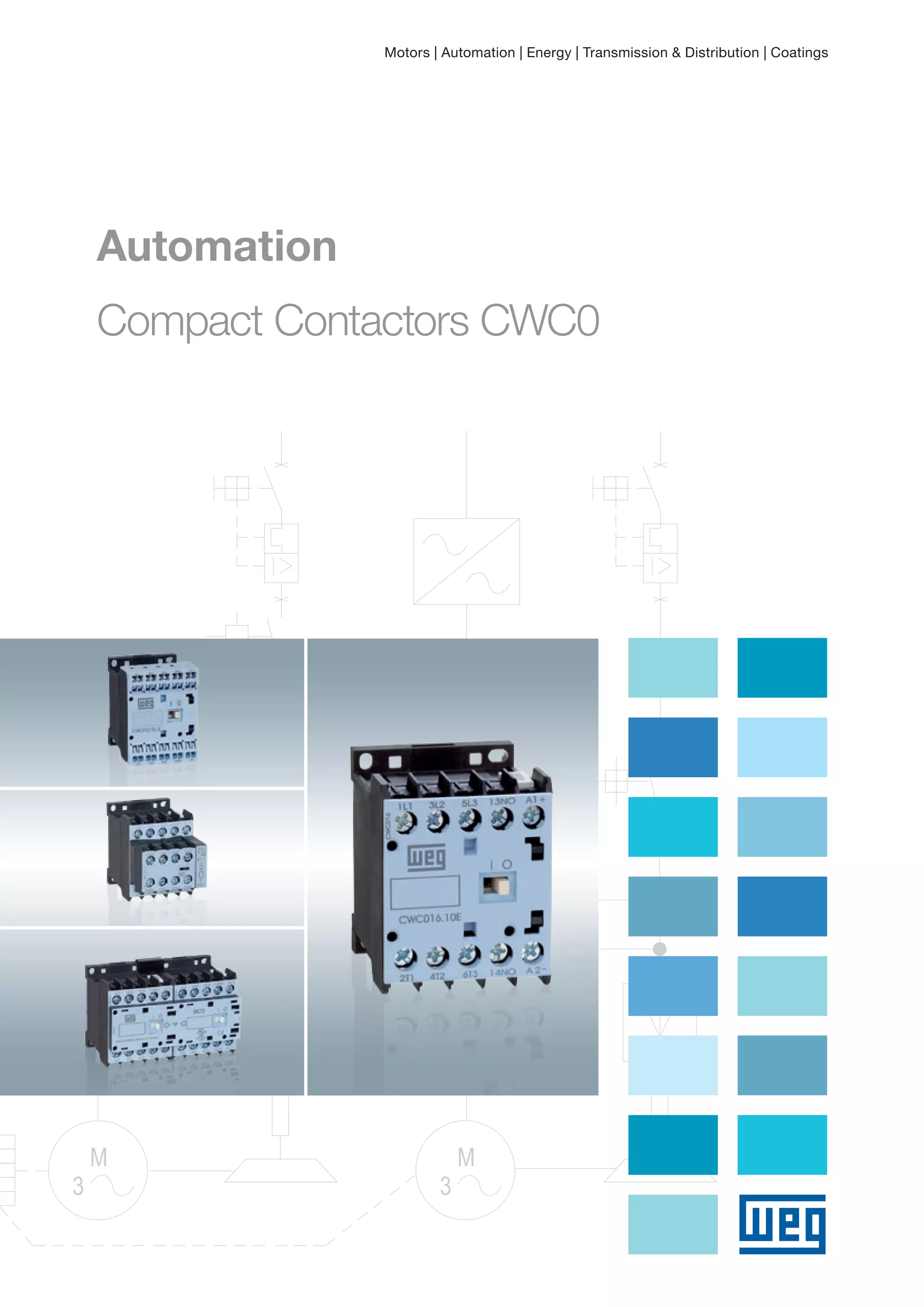
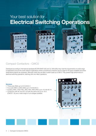
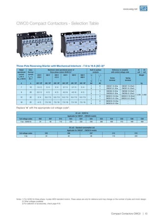
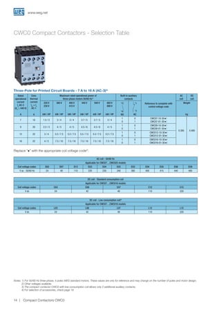
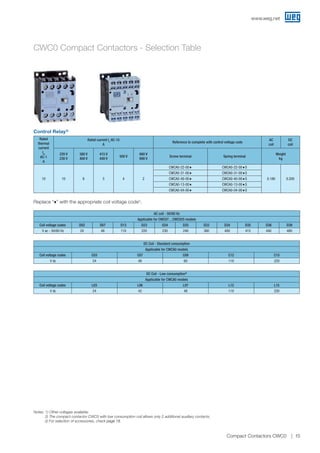
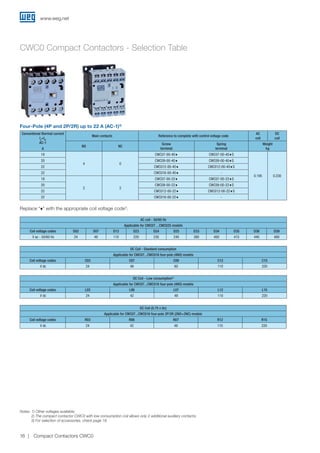
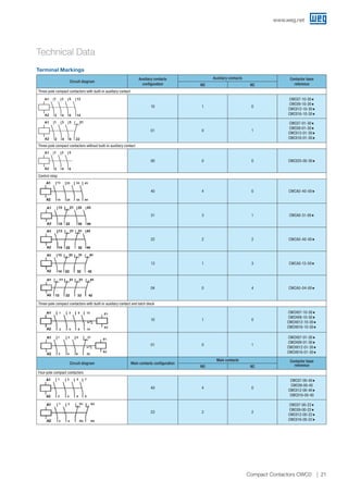
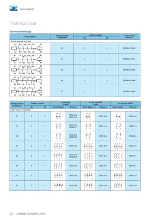
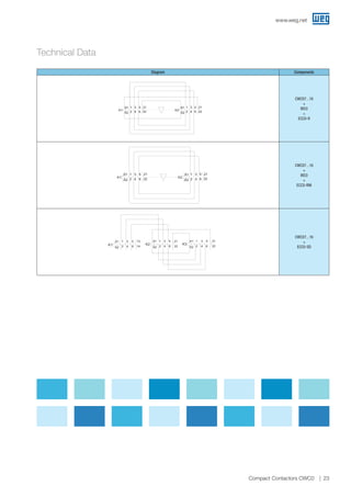
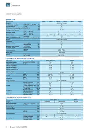
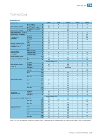
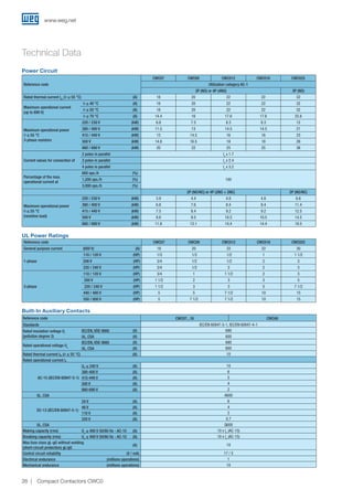
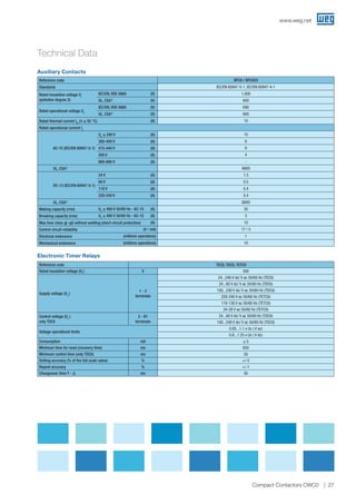
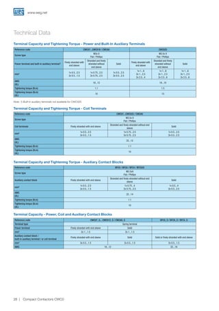
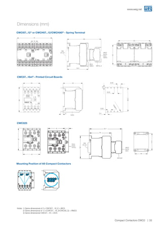
4. Compact Contactors - CWC0
Developed according to international standards IEC/EN 60947 (CE) and UL 508 (USA), they meet the requirements of a wide range
of applications around the world. Ideal for applications where conventional contactors are too large for the space available and where
streamlined projects are necessary. Although small, they are able to switch loads up to 690 V. They present high performance in
electrical switching operations, reaching over one million operations.
JJ Three-pole (3NA) up to 22 A @ AC-3
JJ Four-pole (4NO or 2NO+2NC) up to 16 A @ AC-3
JJ Auxiliary (4NO, 3 NO+1NC, 3NC+1NO, 2NO+2NC) up to 10 A @ AC-15
JJ Contactors with AC and DC coil with the same size up to 16 A
(CWC07...16) and a wide range of coil voltages available
Versions
Your best solution for
Electrical Switching Operations
H
D
W
Compact Contactors CWC04
5. The characteristics of the contactors make them suitable for applications in different segments:
JJ Wood
JJ Food
JJ Refrigeration
JJ Pumping systems
JJ Machines and processes in general
JJ Irrigation systems
JJ Buildings
JJ Illumination
JJ Vehicle barriers and automatic gates
Applications
Compact Contactors CWC0 5
Main Certifications
6. Mechanical Interlock
Mechanical interlock without addition of side space.
It allows the CWC07...16 contactors to be mounted
side by side, providing better use of space in panels
for reversing and star-delta starters. This accessory
is mounted in the front, and no tools are required for
the installation. Its use does not prevent the addition
of auxiliary contact blocks, surge suppressor blocks,
and other accessories connected to the power
terminals.
Safety in Installation
All the contactors have degree of protection IP20 to prevent
inadvertent contacts with the live parts without requiring
additional accessories.
Efficiency in the Mounting
The mounting on DIN rail 35 mm (EN 50022-35) provides
fast and efficient installations. Its mounting base allows up
to four fastening points, making the installation flexible and
totally compatible with most existing contactors, simplifying
its replacement by the CWC0 lines.
Surge Suppressor Blocks
Designed to prevent current or voltage surges on the
command circuit, the suppressor blocks of the CWC0 line
were developed with the clip fastening system without using
cables. The assembly and disassembly do not require any
tools. Available in the versions: varistor, resistor-capacitor,
diode and Zener diode.
www.weg.net
6 Compact Contactors CWC0
7. Indication of Position or State
Front identification of the state of the contactor by means
of indicator in the place marked with “I” (ON) and “O”
(OFF). Contactors, even installed with accessories, allow
the view of their state.
Connection Busbars
Developed for customers that need to save time, avoid
errors and standardize operations in the assembly of
motor starters on electrical panels. Available in the
reversing and star-delta versions, they also allow to add
protections (MPW motor-protective circuit breakers or
RW17 overload relays) together with these contactors.
Mirror and Mechanically Linked Contacts
In order to meet the requirements of the safest and most
demanding machine and equipment applications, the contactors
were developed according to IEC/EN 60947-4-1 - Annex F, about
“Mirror Contacts), and IEC/EN 60947-5-1 - Annex L, about
“Mechanically Linked Contacts.
Built-In Auxiliary Contacts - 1NO or 1NC
They meet the needs of most applications without
requiring any additional contacts, reducing items in the
inventory. They have self-cleaning characteristics by
means of sliding contacts, providing high reliability in low
voltage and current (17 V / 5 mA) switching operations.
IEC/EN 60947-5-1 Symbol
Mechanically Linked
Contacts
IEC/EN 60947-4-1
Symbol Mirror Contacts
www.weg.net
7Compact Contactors CWC0
8. Additional Contact Blocks
Available in the frontal version, they allow the expansion of
4 or 2 auxiliary contacts per contactor. Assembly and
disassembly without tools. They have self-cleaning
characteristics by means of sliding contacts, providing
high reliability in low voltage and current (17 V / 5 mA)
switching operations. Numbering according to EN 50005
and EN 50012.
Drive Control
Low-consumption, direct current coils (5.8 W) enable the
direct drive of the contactors via PLCs, inverter outputs or
soft-starter, without using relay interfaces. Low and
extremely low-consumption coils allow to reduce power
supplies and command transformers, ensuring better use of
the energy resources and lower costs on your electrical
panel.
Wide Range of Accessories
All the accessories are interchangeable between the
CWC07...16 and CWCA0 models, enabling the optimization of
items and greater flexibility of their applications. Example: the
same front contact block, suppressor blocks, interlock and
mechanical retention may be installed in different models of
contactors.
Faster and Securer Connections
The cage clamp connections of the CWC07...16
contactors provide faster installation of power cables and
accessories. Using a screwdriver, it is possible to make
the connections in a shorter time in comparison to screw
terminals. Due to special springs on the connection
terminals, retightening is not necessary, because the
connection system ensures constant pressure on the
cables.
www.weg.net
8 Compact Contactors CWC0
9. Compact Starters
The most compact starters on the market up to 25 A.
Contactors fully compatible with the RW17 overload relays
and MPW18 e MPW40 motor-protective circuit breakers,
enabling the installation of direct on-line starters up to 9.2
kW / 12.5 cv @ 380 V and star-delta starters up to 22 kW /
30 cv @ 380 V.
Timer Blocks
Extremely compact electronic timers only 9 mm wide.
They are installed on the side of the CWC07...25
contactors without tools, allowing timing between 0.3s and
1,800s (30min) at voltages of 24...240 V AC/V DC. Models
with Power up Delay (TEC0), Power down Delay (TDC0)
and for star-delta starters (TETC0).
RMC0 Mechanical Retention Block
It allows to keep the electrical contacts of the contactors
operated without continuous supply of its coil. Ideal for
circuits with a low number of switching operations, such
as: ventilation systems, illumination, etc. The front
mounting of this accessory on two contactors mounted
side by side allows the mechanical retention of one
contactor (K1).
After a command pulse on the coil of contactor K1
(minimum duration of 100ms), this accessory will keep
its contacts retained. For contactor K1 to return to its
initial state, it is necessary a command pulse on the coil
of contactor K2 (RESET), releasing the mechanical
retention of contactor K1. If the coil of contactor K2
keeps energized, the RMC0 accessory will not actuate
on contactor K1. Accessory compatible with CWC07...16
and CWCA contactors, front contact blocks, suppressor
blocks and timers.
K1
K2
www.weg.net
9Compact Contactors CWC0
10. Environmentally Friendly
Manufactured with materials of low impact on the
environment and according to the RoHS international
requirements.
Connectors for CIC0 Printed Circuit Boards
The accessory allows mounting the CWC07...16 and
CWCA contactors with screw terminal on printed circuit
boards. Ideal for OEMs (automatization of vehicle barriers,
automatic gates, fans, etc.) that require operations with
robust components developed for specific applications,
such as the switching of electric motors. Connectors
manufactured with metallic terminals with special coating
for better adherence of the weld and support in plastic
flame resistant material.
Issued by the Parliament and by the European Council, the
RoHS restricts the use of hazardous substances on electronic
products traded in the countries members of the EU,
prohibiting the ingress of new products on the market in case
they contain lead, cadmium, hexavalent chromium, mercury,
polybrominated biphenyl (PBB) and polybrominated diphenyl
ethers (PBDE). The CWC0 line complies with the RoHS
requirements.
www.weg.net
10 Compact Contactors CWC0
12. Notes: 1) For 50/60 Hz three-phase, 4 poles WEG standard motors. These values are only for reference and may change on the number of poles and motor design;
2) Other voltages available;
3) The compact contactor CWC0 with low consumption coil allows only 2 additional auxiliary contacts;
4) For selection of accessories, check page 18.
Three-Pole - 7 A to 22 A (AC-3)4)
Rated
operational
current
Ie
AC-3
(Ue
≤ 440 V)
A
Conv.
thermal
current
Ith
= Ie
AC-1
A
Maximum rated operational power of
three-phase motors 50/60 Hz1)
Built-in auxliary
contacts
Reference to complete with
control voltage code
AC
coil
DC
coil
220 V
230 V
kW /HP
380 V
kW / HP
400 V
415 V
kW / HP
440 V
kW / HP
500 V
kW / HP
660 V
690 V
kW / HP
4
3
NO
2
1
NC
Screw
terminal
Spring
terminal
Weight
kg
7 18 1.5 / 2 3 / 4 3 / 4 3.7 / 5 3.7 / 5 3 / 4
1
0
0
1
CWC07-10-30♦
CWC07-01-30♦
CWC07-10-30♦S
CWC07-01-30♦S
0.195 0.230
9 20 2.2 / 3 4 / 5 4 / 5 4.5 / 6 4.5 / 6 4 / 5
1
0
0
1
CWC09-10-30♦
CWC09-01-30♦
CWC09-10-30♦S
CWC09-01-30♦S
12 22 3 / 4 5.5 / 7.5 5.5 / 7.5 5.5 / 7.5 5.5 / 7.5 5.5 / 7.5
1
0
0
1
CWC012-10-30♦
CWC012-01-30♦
CWC012-10-30♦S
CWC012-01-30♦S
16 22 4 / 5 7.5 / 10 7.5 / 10 7.5 / 10 7.5 / 10 7.5 / 10
1
0
0
1
CWC016-10-30♦
CWC016-01-30♦
-
-
22 32 5.5 / 7.5 11 / 15 11 / 15 11 / 15 11 / 15 11 / 15 0 0 CWC025-00-30♦ - 0.200 -
AC coil - 50/60 Hz
Applicable for CWC07…CWC025 models
Coil voltage codes D02 D07 D13 D23 D24 D25 D33 D34 D35 D36 D39
V ac - 50/60 Hz 24 48 110 220 230 240 380 400 415 440 480
DC coil - Standard consumption coil
Applicable for CWC07…CWC016 models
Coil voltage codes C03 C06 C07 C12 C15
V dc 24 42 48 110 220
DC coil - Low consumption coil3)
Applicable for CWC07…CWC016 models
Coil voltage codes L03 L06 L07 L12 L15
V dc 24 42 48 110 220
CWC0 Compact Contactors - Selection Table
Replace “♦” with the appropriate coil voltage code2)
.
www.weg.net
12 Compact Contactors CWC0
13. Notes: 1) For 50/60 Hz three-phase, 4 poles WEG standard motors. These values are only for reference and may change on the number of poles and motor design;
2) Other voltages available;
3) For selection of accessories, check page A18.
AC coil - 50/60 Hz
Applicable for CWC07…CWC025 models
Coil voltage codes D02 D07 D13 D23 D24 D25 D33 D34 D35 D36 D39
V ac - 50/60 Hz 24 48 110 220 230 240 380 400 415 440 480
Three-Pole Reversing Starter with Mechanical Interlock - 7 A to 16 A (AC-3)3)
Rated
operational
current
Ie
AC-3
(Ue
≤ 440 V)
A
Conv.
thermal
current
Ith
= Ie
AC-1
A
Maximum rated operational power of
three-phase motors 50/60 Hz1)
Built-in auxliary
contacts
Reference to complete
with control voltage code
AC
coil
DC
coil
220 V
230 V
kW / HP
380 V
kW / HP
400 V
415 V
kW / HP
440 V
kW / HP
500 V
kW / HP
660 V
690 V
kW / HP
4
3
NO
2
1
NC
Screw
terminal
Spring
terminal
Weight
kg
7 18 1.5 / 2 3 / 4 3 / 4 3.7 / 5 3.7 / 5 3 / 4
1
0
0
1
CWCI07-10-30♦
CWCI07-01-30♦
CWCI07-10-30♦S
CWCI07-01-30♦S
0.395 0.480
9 20 2.2 / 3 4 / 5 4 / 5 4.5 / 6 4.5 / 6 4 / 5
1
0
0
1
CWCI09-10-30♦
CWCI09-01-30♦
CWCI09-10-30♦S
CWCI09-01-30♦S
12 22 3 / 4 5.5 / 7.5 5.5 / 7.5 5.5 / 7.5 5.5 / 7.5 5.5 / 7.5
1
0
0
1
CWCI012-10-30♦
CWCI012-01-30♦
CWCI012-10-30♦S
CWCI012-01-30♦S
16 22 4 / 5 7.5 / 10 7.5 / 10 7.5 / 10 7.5 / 10 7.5 / 10
1
0
0
1
CWCI016-10-30♦
CWCI016-01-30♦
-
-
DC coil - Standard consumption coil
Applicable for CWCI07…CWCI016 models
Coil voltage codes C03 C06 C07 C12 C15
V dc 24 42 48 110 220
CWC0 Compact Contactors - Selection Table
Replace “♦” with the appropriate coil voltage code2)
.
www.weg.net
13Compact Contactors CWC0
14. Three-Pole for Printed Circuit Boards - 7 A to 16 A (AC-3)4)
Rated
operational
current
Ie
AC-3
(Ue
≤ 440 V)
A
Conv.
thermal
current
Ith
= Ie
AC-1
A
Maximum rated operational power of
three-phase motors 50/60 Hz1)
Built-in auxiliary
contacts
Reference to complete with
control voltage code
AC
coil
DC
coil
220 V
230 V
kW / HP
380 V
kW / HP
400 V
415 V
kW / HP
440 V
kW / HP
500 V
kW / HP
660 V
690 V
kW / HP
4
3
NO
2
1
NC
Weight
kg
7 18 1.5 / 2 3 / 4 3 / 4 3.7 / 5 3.7 / 5 3 / 4
1
0
0
1
CWC07-10-30♦I
CWC07-01-30♦I
0.395 0.480
9 20 2.2 / 3 4 / 5 4 / 5 4.5 / 6 4.5 / 6 4 / 5
1
0
0
1
CWC09-10-30♦I
CWC09-01-30♦I
12 22 3 / 4 5.5 / 7.5 5.5 / 7.5 5.5 / 7.5 5.5 / 7.5 5.5 / 7.5
1
0
0
1
CWC012-10-30♦I
CWC012-01-30♦I
16 22 4 / 5 7.5 / 10 7.5 / 10 7.5 / 10 7.5 / 10 7.5 / 10
1
0
0
1
CWC016-10-30♦I
CWC016-01-30♦I
DC coil - Standard consumption coil
Applicable for CWC07…CWC016 models
Coil voltage codes C03 C06 C07 C12 C15
V dc 24 42 48 110 220
DC coil - Low consumption coil3)
Applicable for CWC07…CWC016 models
Coil voltage codes L03 L06 L07 L12 L15
V dc 24 42 48 110 220
Notes: 1) For 50/60 Hz three-phase, 4 poles WEG standard motors. These values are only for reference and may change on the number of poles and motor design;
2) Other voltages available;
3) The compact contactor CWC0 with low consumption coil allows only 2 additional auxiliary contacts;
4) For selection of accessories, check page 18.
AC coil - 50/60 Hz
Applicable for CWC07…CWC025 models
Coil voltage codes D02 D07 D13 D23 D24 D25 D33 D34 D35 D36 D39
V ac - 50/60 Hz 24 48 110 220 230 240 380 400 415 440 480
CWC0 Compact Contactors - Selection Table
Replace “♦” with the appropriate coil voltage code2)
.
www.weg.net
14 Compact Contactors CWC0
15. Control Relay3)
Rated
thermal
current
Ith
AC-1
A
Rated current Ie
AC-15
A
Reference to complete with control voltage code
AC
coil
DC
coil
220 V
230 V
380 V
400 V
415 V
440 V
500 V
660 V
690 V
Screw terminal Spring terminal
Weight
kg
10 10 6 5 4 2
CWCA0-22-00♦ CWCA0-22-00♦S
0.180 0.200
CWCA0-31-00♦ CWCA0-31-00♦S
CWCA0-40-00♦ CWCA0-40-00♦S
CWCA0-13-00♦ CWCA0-13-00♦S
CWCA0-04-00♦ CWCA0-04-00♦S
DC Coil - Standard consumption
Applicable for CWCA0 models
Coil voltage codes C03 C07 C09 C12 C15
V dc 24 48 60 110 220
DC Coil - Low consumption2)
Applicable for CWCA0 models
Coil voltage codes L03 L06 L07 L12 L15
V dc 24 42 48 110 220
Notes: 1) Other voltages available;
2) The compact contactor CWC0 with low consumption coil allows only 2 additional auxiliary contacts;
3) For selection of accessories, check page 18.
AC coil - 50/60 Hz
Applicable for CWC07…CWC025 models
Coil voltage codes D02 D07 D13 D23 D24 D25 D33 D34 D35 D36 D39
V ac - 50/60 Hz 24 48 110 220 230 240 380 400 415 440 480
CWC0 Compact Contactors - Selection Table
Replace “♦” with the appropriate coil voltage code1)
.
www.weg.net
15Compact Contactors CWC0
16. DC Coil - Low consumption2)
Applicable for CWC07...CWC016 four-pole (4NO) models
Coil voltage codes L03 L06 L07 L12 L15
V dc 24 42 48 110 220
DC Coil (0.75 x Uc)
Applicable for CWC07...CWC016 four-pole 2P/2R (2NO+2NC) models
Coil voltage codes R03 R06 R07 R12 R15
V dc 24 42 48 110 220
Four-Pole (4P and 2P/2R) up to 22 A (AC-1)3)
Conventional thermal current
Ie
=Ith
AC-1
A
Main contacts Reference to complete with control voltage code
AC
coil
DC
coil
NO NC
Screw
terminal
Spring
terminal
Weight
kg
18
4 0
CWC07-00-40♦ CWC07-00-40♦S
0.195 0.230
20 CWC09-00-40♦ CWC09-00-40♦S
22 CWC012-00-40♦ CWC012-00-40♦S
22 CWC016-00-40♦ -
18
2 2
CWC07-00-22♦ CWC07-00-22♦S
20 CWC09-00-22♦ CWC09-00-22♦S
22 CWC012-00-22♦ CWC012-00-22♦S
22 CWC016-00-22♦ -
DC Coil - Standard consumption
Applicable for CWC07...CWC016 four-pole (4NO) models
Coil voltage codes C03 C07 C09 C12 C15
V dc 24 48 60 110 220
Notes: 1) Other voltages available;
2) The compact contactor CWC0 with low consumption coil allows only 2 additional auxiliary contacts;
3) For selection of accessories, check page 18.
AC coil - 50/60 Hz
Applicable for CWC07…CWC025 models
Coil voltage codes D02 D07 D13 D23 D24 D25 D33 D34 D35 D36 D39
V ac - 50/60 Hz 24 48 110 220 230 240 380 400 415 440 480
CWC0 Compact Contactors - Selection Table
Replace “♦” with the appropriate coil voltage code1)
.
www.weg.net
16 Compact Contactors CWC0
17. DC coil - Standard consumption coil
Applicable for CWCH07...CWCH016 models
Coil voltage codes C03 C06 C07 C12 C15
V dc 24 42 48 110 220
Three-Pole with Latch Block - 5.6 A to 12.8 A (AC-3)3)4)
Rated
operational
current
Ie
AC-3
(Ue
≤ 440 V)
A
Conv.
thermal
current
Ith
= Ie
AC-1
A
Maximum rated operational power of
three-phase motors 50/60 Hz1)
Built-in auxiliary
contacts
Reference to complete with control voltage code
AC
coil
DC
coil
220 V
230 V
kW /HP
380 V
kW / HP
400 V
415 V
kW / HP
440 V
kW / HP
500 V
kW / HP
660 V
690 V
kW / HP
4
3
NO
2
1
NC
Screw
terminal
Spring
terminal
Weight
kg
5.6 14.4 1.1 / 1.5 2.2 / 3 2.2 / 3 2.2 / 3 2.2 / 3 3 / 4
1
0
0
1
CWCH7-10-30♦
CWCH7-01-30♦
CWCH7-10-30♦S
CWCH7-01-30♦S
0.395 0.480
7.2 16 1.5 / 2 3 / 4 3 / 4 3.7 / 5 3.7 / 5 3.7 / 5
1
0
0
1
CWCH09-10-30♦
CWCH09-01-30♦
CWCH09-10-30♦S
CWCH09-01-30♦S
9.6 17.6 2.2 / 3 4.5 / 6 4.5 / 6 4.5 / 6 5.5 / 7.5 5.5 / 7.5
1
0
0
1
CWCH012-10-30♦
CWCH012-01-30♦
CWCH012-10-30♦S
CWCH012-01-30♦S
12.8 17.6 3 / 4 5.5 / 7.5 5.5 / 7.5 5.5 / 7.5 7.5 / 10 7.5 / 10
1
0
0
1
CWCH016-10-30♦
CWCH016-01-30♦
CWCH016-10-30♦S
CWCH016-01-30♦S
Notes: 1) For 50/60 Hz three-phase, 4 poles WEG standard motors. These values are only for reference and may change depending on the number of poles and
motor design;
2) Other voltages available;
3) For selection of accessories, check page 18;
4) For further information about CWCH0 an its operation, check page 30.
Control Relay with Latch Block
Rated operational current Ie Number of auxiliary contacts Reference code to complete with voltage code
AC
coil
DC
coil
AC-14 / AC-15
(Ue
≤ 230 V)
A
DC-13
(Ue
≤ 24 V)
A
4
3
NO
2
1
NC
Screw
terminal
Spring
terminal
Weight
kg
8 4.8 2 2 CWCHA0-22-00♦ CWCHA0-22-00♦S
0.377 0.444
8 4.8 3 1 CWCHA0-31-00♦ CWCHA0-31-00♦S
8 4.8 4 - CWCHA0-40-00♦ CWCHA0-40-00♦S
8 4.8 1 3 CWCHA0-13-00♦ CWCHA0-13-00♦S
8 4.8 - 4 CWCHA0-04-00♦ CWCHA0-04-00♦S
AC coil - 50/60 Hz
Applicable for CWC07…CWC025 models
Coil voltage codes D02 D07 D13 D23 D24 D25 D33 D34 D35 D36 D39
V ac - 50/60 Hz 24 48 110 220 230 240 380 400 415 440 480
CWC0 Compact Contactors - Selection Table
Replace “♦” with the appropriate coil voltage code2)
.
www.weg.net
17Compact Contactors CWC0
18. Mechanical Interlock2)
Mechanical Latch Block2)
Illustrative picture
For use
with
Description Reference code
Weight
kg
CWC07...16
CWCA0
- Front mouting;
- For the mechanical interlock using 2 compact contactors
(AC or DC coil);
- Can be mounted with the following accessories:
auxiliary contact block, surge suppressor and timers.
BIC0 0.014
Illustrative picture
For use
with
Description Reference code
Weight
kg
CWC07...16
CWCA0
- Front mouting;
- For the mechanical interlock using 2 compact contactors
(AC or DC coil);
- Can be mounted with the following accessories:
auxiliary contact block, surge suppressor and timers.
RMC0 0.014
Accessories
Auxiliary Contact Blocks
Illustrative
picture
For use
with
Max.
number of
contacts/
compact
contator
Auxiliary
contacts
For use with CWC0
(3 pole)
For use with CWC0
(4 pole)
For use with CWCA0 Weight
kg
NO NC
Reference code Reference code Reference code
Screw
terminal
Spring
terminal
Screw
terminal
Spring
terminal
Screw
terminal
Spring
terminal
CWC07...16
CWCA0
2
2 0 BFC0-20 BFC0-20S BFC4-20 BFC4-20S BFCA-20 BFCA-20S
0.03
1 1 BFC0-11 BFC0-11S BFC4-11 BFC4-11S BFCA-11 BFCA-11S
0 2 BFC0-02 BFC0-02S BFC4-02 BFC4-02S BFCA-02 BFCA-02S
4
4 0 BFC0-401)
BFC0-40S1)
BFC4-401)
BFC4-40S1)
BFCA-401)
BFCA-40S1)
2 2 BFC0-221)
BFC0-22S1)
BFC4-221)
BFC4-22S1)
BFCA-221)
BFCA-22S1)
0 4 BFC0-042)
BFC0-04S2)
BFC4-042)
BFC4-04S2)
BFCA-042)
BFCA-04S2)
3 1 BFC0-311)
BFC0-31S1)
BFC4-311)
BFC4-31S1)
BFCA-311)
BFCA-31S1)
1 3 BFC0-132)
BFC0-13S2)
BFC4-132)
BFC4-13S2)
BFCA-132)
BFCA-13S2)
CWC025
2
2 0 BFC025-20 - - -
1 1 BFC025-11 - - -
0 2 BFC025-02 - - -
4 2 2 BFC025-22 - - -
Notes: 1) The compact contactors CWC0 with DC low consumption coils allows only 2 additional auxiliary contacts. For applications that use 4 auxiliary contacts
use CWC0 with standard DC coils.
2) Not suitable to be used with CWC0 compact contactors or CWCA0 control relays with DC Low Consumption coils (coil voltage code “L”).
www.weg.net
18 Compact Contactors CWC0
19. Accessories
Eletronic Timing Relay
JJ Right-side fast mounting
JJ Up to 30 minutes timing
JJ LED status indication
Illustrative picture Function Timing Voltages Reference code
Weight
kg
On-Delay (TECO)
3 - 0.3 to 3 seconds
24-240 V 50/60 Hz - DC
TEC0-U003S-E05
0.02
10 - 1 to 10 seconds TEC0-U010S-E05
30 - 3 to 30 seconds TEC0-U030S-E05
60 - 6 to 60 seconds TEC0-U060S-E05
100 - 10 to 100 seconds TEC0-U100S-E05
300 - 30 to 300 seconds TEC0-U300S-E05
1,800 - 180 to 1,800 seconds TEC0-U030M-E05
Off-Delay (TDCO)
-
24-60 V 50/60 Hz - DC
100-240 V 50/60 Hz - DC
24-60 V ac/dc 100-240 V ac/dc
3 - 0.3 to 3 seconds TDC0-U010S-E04 TDC0-U003S-E09
10 - 1 to 10 seconds TDC0-U003S-E04 TDC0-U010S-E09
30 - 3 to 30 seconds TDC0-U030S-E04 TDC0-U030S-E09
60 - 6 to 60 seconds TDC0-U060S-E04 TDC0-U060S-E09
100 - 10 to 100 seconds TDC0-U100S-E04 TDC0-U100S-E09
300 - 30 to 300 seconds TDC0-U300S-E04 TDC0-U300S-E09
1,800 - 180 to 1,800 seconds TDC0-U030M-E04 TDC0-U030M-E09
Start-Delta (TETCO) 30 - 3 to 30 seconds
24-28 V 50/60 Hz TETC0-U030S-D52
110-130 V 50/60 Hz TETC0-U030S-D61
220-240 V 50/60 Hz TETC0-U030S-D66
Functions On-Delay TEC0 Off-Delay TDC0 Start-Delta TETC0
Functionals diagrams
Led On
Led Off
Diagrams
Surge Suppressors
JJ Fast front mounting (clip on)
JJ Can be mounted with all the accessories
Illustrative picture For use with Circuit diagram Voltages Reference code
Weight
kg
CWC07...25
CWCA0
12-24 V 50/60 Hz RCC0-1 D49
0.008
24-48 V 50/60 Hz RCC0-2 D53
50-127 V 50/60 Hz RCC0-3 D55
130-250 V 50/60 Hz RCC0-4 D63
275-380 V 50/60 Hz RCC0-5 D84
400-510 V 50/60 Hz RCC0-6 D73
CWC07...16
CWCA0
180...230 V 50/60 Hz RCAC0 D871)
CWC07...25
CWCA0
12-48 V 50/60 Hz / 12-60 V dc VRC0-1 E49
50-127 V 50/60 Hz / 60-180 V dc VRC0-2 E34
130-250V 50/60 Hz / 180-300V dc VRC0-3 E50
277-380V 50/60 Hz / 300-510V dc VRC0-4 E41
400-510 V 50/60 Hz VRC0-5 D73
CWC07...16
CWCA0
12-600 V dc DIC0-1 C33
12...250 V dc DIZC0 C26
Note: 1) To protect snubbers against overvoltage peaks caused by the switching off of the contactors with AC coils. It is recommended to use in circuits with residual
current over than (Us/230 V)x1.4 mA. (Us = Rated voltage).
www.weg.net
19Compact Contactors CWC0
20. Star-Delta Wiring
Reversing Wiring Kits
Rated operational
current Ie
AC - 3
(Ue
≤ 440 V)
A
Max. rated operational power of three-phase motors 50/60 Hz
Compact contactors
Reference code
Weight
kg
220-230 V
kW / HP
400-415 V
kW / HP
660-690 V
kW / HP
K1 = K2 K3
12 3.7 / 5 5.5 / 7.5 5.5 / 7.5 CWC07
CWC07
ECC0-SD 0.1318 3.7 / 5 7.5 / 10 9.2 / 12.5 CWC012
25 5.5 / 7.5 11 / 15 15 / 20 CWC016 CWC09
Rated operational
current Ie
AC - 3
(Ue
≤ 440 V)
A
Max. rated operational power of three-phase motors 50/60 Hz
Compact
contactors
Reference code
Weight
kg
220 V
230 V
kW /HP
380 V
kW / HP
400 V
415 V
kW / HP
440 V
kW / HP
500 V
kW / HP
660 V
690 V
kW / HP
K1 = K2
7 1.5 / 2 3 / 4 3 / 4 3.7 / 5 3.7 / 5 3 / 4 CWC07
ECC0-R
(with electrical
interlock)
0.139 2.2 / 3 4 / 5 4 / 5 4.5 / 6 4.5 / 6 4 / 5 CWC09
ECC0-RNI
(without electrical
interlock)
12 3 / 4 5.5 / 7.5 5.5 / 7.5 5.5 / 7.5 5.5 / 7.5 5.5 / 7.5 CWC012
16 4 / 5 7.5 / 10 7.5 / 10 7.5 / 10 7.5 / 10 7.5 / 10 CWC016
Printed Circuit Board Link Module
Illustrative picture For use with Description Reference code
Weight
kg
CWC07...16
CWCA0
- Direct mounting on the terminals
- Allows direct mounting on printed circuit board
- Same current capacity (up to 16 A in AC-3 and 22 A in AC-1)
CIC0 0.130
Accessories
www.weg.net
20 Compact Contactors CWC0
24. General Data
Reference code CWCA0 CWC07 CWC09 CWC012 CWC016 CWC025
Standards IEC/EN 60947 / UL 508
Rated insulation voltage Ui
(pollution degree 3)
IEC/EN 60947-4-1, VDE 0660 (V) 690
UL, CSA (V) 600
Rated impuse withstand voltage Uimp
(IEC/EN 60947-1) (kV) 4
Rated operational frequency (Hz) 25...400
Mechanical lifespan
AC coil Ops x 10”6”
10 3
DC coil Ops x 10”6”
12 -
Electrical lifespan Ie
AC-3 Ops x 10”6”
- 1.4 1.3 1.2 1.1 0.6
Degree of protection (VDE 0160)
Main circuits IP20
Control circuits and auxiliary contacts IP20
Mounting Screw or DIN rail 35 mm
Coil terminals 2
Vibration resistance
Contactor open (g) 2
Contactor closed (g) 4
Mechanical shock resistance
(½ sinusoid = 11ms)
Contactor open (g) 6
Contactor closed (g) 10
Ambient temperature
Operation -25 °C ...+55 °C
Storage -55 °C ... +80 °C
Normal values Up to 3,000 m
Altitude
90% Ie
/ 80% Ue 3,000 to 4,000 m
80% Ie
/ 75% Ue 4,000 to 5,000 m
Technical Data
Control Circuit - Alternating Current (AC)
Reference code CWCA0, CWC07...16 CWC025
Rated insulation voltage Ui
(pollution degree 3)
IEC/EN 60947-4-1, VDE 0660 (V) 1,000 1,000
UL, CSA (V) 600 600
Coils rated voltage 50 Hz (V) 10...550 10...550
Coils rated voltage 60 Hz (V) 12...660 12...660
Coils rated voltage 50/60 Hz (V) 12...660 12...660
Coils rated voltage
Coil operating limits (xUs) 0.85...1.1
Coil 60 Hz
Pick up (xUs) 0.4...0.76 0.4...0.76
Drop out (xUs) 0.25...0.65 0.25...0.65
Coil 50/60 Hz
Pick up (xUs) 0.5...0.8 0.5...0.8
Drop out (xUs) 0.2...0.6 0.2...0.6
Average consumption 1.0 x Us coil cold state
Coil 60 Hz
Magnetic circuit closed (VA) 2.5...3.5 10.8....13.2
Power factor (cos ϕ) 0.28 0.32
Power dissipation per pole (W) 2.6 -
Magnetic circuit closing (VA) 35 72
Power factor (cos ϕ) 0.85 0.93
Coil 50/60 Hz
Magnetic circuit closed (VA) 2...3 4.56...5.8
Magnetic circuit closing (VA) 30 58
Average time
Closing NO contacts (ms) 8...20 13...16
Opening NO contacts (ms) 6...13 13.5...17
Reference code CWCA0, CWC07...16 CWC07...16
Coil type Conventional Low consumption 4P (2P/2R)
Rated insulation voltage Ui
(pollution degree 3)
IEC/EN 60947-4-1, VDE 0660 (V) 1,000
UL, CSA (V) 600
Standard voltages (V) 12...440
Coil operating limits (xUs) 0.85...1.1
Pick up (xUs) 0.4...0.7
Drop out (xUs) 0.15...0.4
Power consumption 1.0 x Us coil cold state
Magnetic circuit closed (W) 2.6...3.7 1.7...2.7 2.9...4
Magnetic circuit closing (W) 2.6...3.7 1.7...2.7 2.9...4
Operation time
Closing NO contacts (ms) 35...45
Opening NO contacts (ms) 7...12
Control Circuit - Direct Current (DC)
www.weg.net
24 Compact Contactors CWC0
25. Power Circuit
Reference code CWC07 CWC09 CWC012 CWC016 CWC025
Rated operational current Ie
AC-3 (Ue
≤ 440 V) (A) 7 9 12 16 22
AC-4 (Ue
≤ 440 V) (A) 2.8 3.5 4.5 5 9
AC-1 (θ ≤ 55 °C, Ue
≤ 690 V) (A) 18 20 22 22 32
Rated operational voltage Ue
IEC/EN 60947-4-1, VDE 0660 (V) 690
UL, CSA1)
(V) 600
Rated thermal current Ith
(θ ≤ 55 °C) (A) 18 20 22 22 32
Making capacity - IEC/EN 60947 (A) 70 90 120 160 250
Breaking capacity
IEC/EN 60947
(Ue
≤400 V) (A) 50 72 96 128 200
(Ue
=500 V) (A) 50 72 96 128 200
(Ue
=690 V) (A) 35 54 72 96 150
Short-time current (no current
flowing during recovery time of
10 min and θ ≤ 40 °C)
1 seg (A) 250 250 250 250 -
5 seg (A) 125 125 125 125 -
10 seg (A) 95 95 95 95 -
30 seg (A) 70 70 70 70 -
1 min (A) 50 50 50 50 -
3 min (A) 40 40 40 40 -
Protection against
short-circuits with
fuses (gL/gG)
@600 V - UL/CSA1)
(kA) 5
Coordination type 1 (A) 35 35 35 35 50
Coordination type 2 (A) 20 20 25 25 35
Average impedance per pole (mΩ) 6 6 5 5 6
Average power dissipation per pole
AC-1 (W) 1.9 2.4 2.4 2.4 6.1
AC-3 (W) 0.3 0.5 0.7 1.3 3.8
Utilization category AC-3
Rated operational current Ie
(θ ≤ 55 °C)
Ue
≤ 440 V (A) 7 9 12 16 22
Ue
≤ 500 V (A) 6.2 7.5 8.8 13 16
Ue
≤ 690 V (A) 4.5 5.5 6.6 10 13
Ue
≤ 1,000 V (A) Not available
Rated operational power1)
220 / 230 V
(kW) 1.5 2.2 3 3.7 5.5
(cv) 2 3 4 5 7.5
380 / V (kW) 3 3.7 5.5 7.5 11
(cv) 4 5 7.5 10 15
400 / 415 V (kW) 3 3.7 5.5 7.5 11
(cv) 4 5 7.5 10 15
440 V (kW) 3.7 4.5 5.5 7.5 11
(cv) 5 6 7.5 10 15
500 V (kW) 3.7 4.5 5.5 7.5 11
(cv) 5 6 7.5 10 15
660 / 690 V (kW) 3 3.7 5.5 7.5 11
(cv) 4 5 7.5 10 15
Max. electrical
operational per hour
600 ops./h (%) 100 100 100 100 100
1,200 ops./h (%) 75 75 75 75 75
3,000 ops./h (%) 50 50 50 50 50
Utilization category AC-4
Rated operational current Ie
AC-4 (Ue
≤ 440 V) (A) 2.8 3.5 4.5 5 9
Rated operational power1)
(200,000 operations)
220 / 230 V
(kW) 0.55 0.75 0.75 1.1 2.2
(cv) 0.7 1 1 1.5 2.9
380 / 400 V
(kW) 1.1 1.1 1.8 2.2 4
(cv) 1.5 1.5 2.4 2.9 5.4
415 V
(kW) 1.1 1.5 2.2 2.2 4.5
(cv) 1.5 2 2.9 2.9 6
440 V
(kW) 1.1 1.5 2.2 2.2 4.5
(cv) 1.5 2 2.9 2.9 6
500 V
(kW) 1.1 1.5 2.2 2.2 4.5
(cv) 1.5 2 2.9 2.9 6
660 / 690 V
(kW) 1.1 1.5 2.2 2.2 4.5
(cv) 1.5 2 2.9 2.9 6
Note: 1) For 50/60 Hz three-phase, 4 poles WEG standard motors. These values are only for reference and may change on the number of poles and motor design.
Technical Data
www.weg.net
25Compact Contactors CWC0
26. Power Circuit
Reference code
CWC07 CWC09 CWC012 CWC016 CWC025
Utilization category AC-1
3P (NO) or 4P (4NO) 3P (NO)
Rated thermal current Ith
(θ ≤ 55 °C) (A) 18 20 22 22 32
Maximum operational current
(up to 690 V)
θ ≤ 40 °C (A) 18 20 22 22 32
θ ≤ 55 °C (A) 18 20 22 22 32
θ ≤ 70 °C (A) 14.4 16 17.6 17.6 25.6
Maximum operational power
θ ≤ 55 °C
3-phase resistors
220 / 230 V (kW) 6.8 7.5 8.3 8.3 12
380 / 400 V (kW) 11.5 13 14.5 14.5 21
415 / 440 V (kW) 13 14.5 16 16 23
500 V (kW) 14.8 16.5 18 18 26
660 / 690 V (kW) 20 22 25 25 36
Current values for connection of
2 poles in parallel Ie
x 1.7
3 poles in parallel Ie
x 2.4
4 poles in parallel Ie
x 3.2
Percentage of the max.
operational current at
600 ops./h (%)
1001,200 ops./h (%)
3,000 ops./h (%)
2P (NO/NC) or 4P (2NO + 2NC) 2P (NO/NC)
Maximum operational power
θ ≤ 55 °C
(resistive load)
220 / 230 V (kW) 3.9 4.4 4.8 4.8 6.6
380 / 400 V (kW) 6.8 7.6 8.4 8.4 11.4
415 / 440 V (kW) 7.5 8.4 9.2 9.2 12.5
500 V (kW) 8.6 9.5 10.5 10.5 14.5
660 / 690 V (kW) 11.8 13.1 14.4 14.4 19.5
Built-In Auxiliary Contacts
UL Power Ratings
Reference code CWC07...16 CWCA0
Standards IEC/EN 60947-5-1, IEC/EN 60947-4-1
Rated insulation voltage Ui
(pollution degree 3)
IEC/EN, VDE 0660 (V) 690
UL, CSA (V) 600
Rated operational voltage Ue
IEC/EN, VDE 0660 (V) 690
UL, CSA (V) 600
Rated thermal current Ith (θ ≤ 55 °C) (A) 10
Rated operational current Ie
AC-15 (IEC/EN 60947-5-1)
Ue ≤ 240 V (A) 10
380-400 V (A) 6
415-440 V (A) 5
500 V (A) 4
660-690 V (A) 2
UL, CSA A600
DC-13 (IEC/EN 60947-5-1)
24 V (A) 6
48 V (A) 4
110 V (A) 2
220 V (A) 0.7
UL, CSA Q600
Making capacity (rms) Ue
≤ 400 V 50/60 Hz - AC-15 (A) 10 x Ie
(AC-15)
Breaking capacity (rms) Ue
≤ 400 V 50/60 Hz - AC-15 (A) 10 x Ie
(AC-15)
Max.fuse class gL-gG without welding
(short-circuit protection) gL/gG
(A) 10
Control circuit reliability (V / mA) 17 / 5
Electrical endurance (millions operations) 1
Mechanical endurance (millions operations) 10
Technical Data
Reference code CWC07 CWC09 CWC012 CWC016 CWC025
General purpose current (600 V) (A) 18 20 22 22 30
1-phase
110 / 120 V (HP) 1/3 1/3 1/2 1 1 1/2
208 V (HP) 3/4 1/2 1/2 2 3
220 / 240 V (HP) 3/4 1/2 2 2 3
3-phase
110 / 120 V (HP) 3/4 1 1 1/2 2 3
200 V (HP) 1 1/2 2 3 3 5
220 / 240 V (HP) 1 1/2 3 3 5 7 1/2
440 / 480 V (HP) 5 5 7 1/2 10 15
550 / 600 V (HP) 5 7 1/2 7 1/2 10 15
www.weg.net
26 Compact Contactors CWC0
27. Auxiliary Contacts
Reference code BFC0 / BFC025
Standards IEC/EN 60947-5-1, IEC/EN 60947-4-1
Rated insulation voltage Ui
(pollution degree 3)
IEC/EN, VDE 0660 (V) 1,000
UL, CSA1)
(V) 600
Rated operational voltage Ue
IEC/EN, VDE 0660 (V) 690
UL, CSA1)
(V) 600
Rated thermal current Ith
(θ ≤ 55 °C) (A) 10
Rated operational current Ie
AC-15 (IEC/EN 60947-5-1)
Ue
≤ 240 V (A) 10
380-400 V (A) 6
415-440 V (A) 6
500 V (A) 4
660-690 V (A) -
UL, CSA1) A600
DC-13 (IEC/EN 60947-5-1)
24 V (A) 1.5
60 V (A) 0.5
110 V (A) 0.4
220-240 V (A) 0.4
UL, CSA1) Q600
Making capacity (rms) Ue
≤ 400 V 50/60 Hz - AC-15 (A) 30
Breaking capacity (rms) Ue
≤ 400 V 50/60 Hz - AC-15 (A) 3
Max.fuse class gL-gG without welding (short-circuit protection) (A) 10
Control circuit reliability (V / mA) 17 / 5
Electrical endurance (millions operations) 1
Mechanical endurance (millions operations) 10
Reference code TEC0, TDC0, TETC0
Rated insulation voltage (Ui
) V 300
Supply voltage (Ue
)
1 - 2
terminals
24...240 V dc/ V ac 50/60 Hz (TEC0)
24...60 V dc/ V ac 50/60 Hz (TDC0)
100...240 V dc/ V ac 50/60 Hz (TDC0)
220-240 V ac 50/60 Hz (TETC0)
110-130 V ac 50/60 Hz (TETC0)
24-28 V ac 50/60 Hz (TETC0)
Control voltage (Uc
)
only TDC0
2 - B1
terminals
24...60 V dc/ V ac 50/60 Hz (TDC0)
100...240 V dc/ V ac 50/60 Hz (TDC0)
Voltage operational limits
0.85...1.1 x Uc ( V ac)
0.8...1.25 x Uc ( V dc)
Consumption mA ≤ 5
Minimum time for reset (recovery time) ms 650
Minimum control time (only TDC0) ms 50
Setting accuracy (% of the full scale value) % +/-5
Repeat accuracy % +/-1
Changeover time Y - ∆ ms 50
Technical Data
Electronic Timer Relays
www.weg.net
27Compact Contactors CWC0
28. Reference code CWC07...CWC016 / CWCA0 CWC025
Screw type
M3x 8
Flat / Phillips
M3.5x 9
Flat / Phillips
Power terminal and built-in auxiliary terminal1) Finely stranded with
end sleeve
Stranded and finely
stranded without
end sleeve
Solid
Finely stranded with
end sleeve
Stranded and finely
stranded without
end sleeve
Solid
mm²
1x 0.5...2.5
2x 0.5...1.5
1x 0.75...2.5
2x 0.75...2.5
1x 0.5...2.5
2x 0.5...2.5
1x 1...6
2x 1...2.5
2x 2.5...4
1x 1...6
2x 1...2.5
2x 2.5...6
1x 1...6
2x 1...2.5
2x 2.5...6
AWG
(UL)
18...12 18...10
Tightening torque (N.m) 1.1 1.5
Tightening torque (lb.in)
(UL)
10 13
Reference code CWC07...CWC025 / CWCA0
Screw type
M3.5x 8
Flat / Phillips
Coil terminals Finely stranded with end sleeve
Stranded and finely stranded without end
sleeve
Solid
mm²
1x 0.5...2.5
2x 0.5...1.5
1x 0.75...2.5
2x 0.75...2.5
1x 0.5...2.5
2x 0.5...2.5
AWG
(UL)
22...12
Tightening torque (N.m) 1.1
Tightening torque (lb.in)
(UL)
10
Reference code BFC0 / BFCA / BFC4 / BFC025
Screw type
M3.5x9
Flat / Phillips
Auxiliary contact block Finely stranded with end sleeve
Stranded and finely stranded without end
sleeve
Solid
mm²
1x 0.5...2.5
2x 0.5...1.5
1x 0.75...4
2x 0.75...2.5
1x 0.5...4
2x 0.5...2.5
AWG
(UL)
22...14
Tightening torque (N.m) 1.1
Tightening torque (lb.in)
(UL)
10
Reference code CWC07_S... CWC012_S / CWCA0_S BFC0_S / BFCA_S / BFC4_S
Terminal type Spring terminal
Power terminal Finely stranded with end sleeve Solid
mm² 2x 1...1.5 2x 1...1.5
Auxiliary contact block /
built-in auxiliary terminal / or coil terminal
Finely stranded with end sleeve Solid Solid or finely stranded with end sleeve
mm² 2x 0.5...1.5 2x 0.5...1.5 2x 0.5...1.5
AWG 18...12 22...16
Technical Data
Terminal Capacity and Tightening Torque - Power and Built-In Auxiliary Terminals
Terminal Capacity and Tightening Torque - Auxiliary Contact Blocks
Terminal Capacity - Power, Coil and Auxiliary Contact Blocks
Note: 1) Built-in auxiliary terminals not available for CWC025.
Terminal Capacity and Tightening Torque - Coil Terminals
www.weg.net
28 Compact Contactors CWC0
30. Functional Diagram
Operation Description of Latch Block RMC0 or CWCH0
Latch compact
contactors
K1
Latch compact
contactors
K1
2 x CWC07...16 / CWCA0 + RMC0
“RESET”
compact
contactors K2
“RESET”
compact
contactors K2
CWCH07...16
or
JJ After a minimum pulse of 100ms on compact contactors coil (K1), the RMC0 will keep K1 contacts switched on.
JJ The compact contactors K1 will only return to rest position after compact contactors coil (K2) be energized by a releasing pulse.
JJ The mechanical latch will always and only happen on compact contactors (K1).
Note: if RESET compact contactors coil (K2) remains energized, the latching of compact contactors (K1) is not enabled.
Latching compact contactors
K1 status of NO contacts
(auxiliary and/or power)
A1
A2
K1
V
E1/A1
E2/A2
K2
Minimum time to ensure mechanical
latch 100ms
Time
Time
Time
Closed
Open Open
Minimum time to ensure
mechanical unlatch 100ms
Technical Data
www.weg.net
30 Compact Contactors CWC0
32. 60
45
81
54.4
38
52
TDC0
TEC0
TETC0
9
CWC07...12_S
60
45
CWC07...12_S
RCC0
VRC0
DIC0
DIZC0
BFC0_S
DIN
35 mm VRC0
RCC0
DIC0
DIZC0
60
45
81
54.4
38
52
TDC0
TEC0
TETC0
9
CWC07...12_S
60
45
CWC07...12_S
RCC0
VRC0
DIC0
DIZC0
BFC0_S
DIN
35 mm
60
45
81
54.4
38
52
TDC0
TEC0
TETC0
9
CWC07...12_S
60
45
CWC07...12_S
RCC0
VRC0
DIC0
DIZC0
BFC0_S
DIN
35 mm
Dimensions (mm)
45
58
CWCI07...161)
+ ECC0-R and CWCH07...162)
- Screw Terminal
CWC07...16 and CWCA0 - (AC and DC Coil) - Screw Terminal
CWC07...012_S, and CWCA0_S - (AC and DC Coil) - Spring Terminal
60
45
81
54.4
38
52
TDC0
TEC0
TETC0
9
CWC07...12_S
60
45
CWC07...12_S
RCC0
VRC0
DIC0
DIZC0
BFC0_S
DIN
35 mm
18
7
ECC0-R/SD
BIC0
RMC0
BFC0
VRC0
RCC0
DIC0
DIZC0
68.8
DIN
35 mm
9
BFC0_S
38
60
TEC0
TDC0
TETC0
DIN
35 mm
TEC0
TDC0
TETC0
DIN
35 mm
BFC0
VRC0
RCC0
DIC0
DIZC0
9
Notes: 1) Same dimensional of 2 x CWC07...16 + BIC0.
2) Same dimensional of 2 x (CWC07...16/CWCA0) + RMC0.
90 86
52
85
52
60
45 45
81
52
54.4
58
58
45
52
78
51
38
45
www.weg.net
32 Compact Contactors CWC0
33. Dimensions (mm)
CWC025
Mounting Position of All Compact Contactors
360°360°
30°30°30°30°
CWC07...16♦I3)
- Printed Circuit Boards
CWCI07...121)
or CWCH07...12/CWCHA02)
- Spring Terminal
91
18
52
84
88
54.4
DIN
35 mm
BIC0
RMC0
RCC0
VRC0
DIC0
DIZC0
BFC0_S
58
45
TEC0
TDC0
TETC0 VRC0
RCC0
DIC0
82.7
BFC025
38
51.6
56
DIN
35 mm
66
45 9
CIC0
1.9
5.4
8.55
8.55
8.55
62.2
10xØ2.3
6
DIN
35 mm
54.4
BIC0
RMC0 BIFC0_S
VRC0
RCC0
DIC0
DIZC0
Notes: 1) Same dimensional of 2 x CWCI07...16_S + BIC0.
2) Same dimensional of 2 x (CWC07...16_S/CWCA0_S) + RMC0.
3) Same dimensional CWC07...16 + CIC0.
58
45
58.1
45 52
91
18
88
84
52
www.weg.net
33Compact Contactors CWC0
34. Global presence is essential,
as much as understanding your needs.
Global Presence
With more than 30.000 employees worldwide, WEG is one of the largest electric motors, electronic equipments and systems
manufacturers. We are constantly expanding our portfolio of products and services with expertise and market knowledge. We
create integrated and customized solutions ranging from innovative products to complete after-sales service.
WEG’s know-how guarantees our Compact Contactors CWC0 is the right choice for your application and business, assuring
safety, efficiency and reliability.
Partnership is to create solutions that suits your needs
Competitive edge is to unite technology and inovation
Availability is to have a global support network
Compact Contactors CWC034
35. High performance and reliable products to
improve your production process.
Know More
Excelence is to provide a whole solution in industrial automation that improves
our customers productivity.
Visit: www.weg.net youtube.com/wegvideos
Compact Contactors CWC0 35
36. WEG Group - Automation Business Unit
Jaraguá do Sul - SC - Brazil
Phone: +55 47 3276 4000
automacao@weg.net
www.weg.net
Cod:50069462|Rev:01|Date(m/y):01/2017
Thevaluesshownaresubjecttochangewithoutpriornotice.
For those countries where there is not a WEG own operation, find our local distributor at www.weg.net.
WEG Worldwide Operations
ARGENTINA
San Francisco - Cordoba
Phone: +54 3564 421484
info-ar@weg.net
Cordoba - Cordoba
Phone: +54 351 4641366
weg-morbe@weg.com.ar
Buenos Aires
Phone: +54 11 42998000
ventas@pulverlux.com.ar
AUSTRALIA
Scoresby - Victoria
Phone: +61 3 97654600
info-au@weg.net
AUSTRIA
Markt Piesting - Wiener
Neustadt-Land
Phone: +43 2633 4040
watt@wattdrive.com
BELGIUM
Nivelles - Belgium
Phone: +32 67 888420
info-be@weg.net
BRAZIL
Jaraguá do Sul - Santa Catarina
Phone: +55 47 32764000
info-br@weg.net
CHILE
La Reina - Santiago
Phone: +56 2 27848900
info-cl@weg.net
CHINA
Nantong - Jiangsu
Phone: +86 513 85989333
info-cn@weg.net
Changzhou – Jiangsu
Phone: +86 519 88067692
info-cn@weg.net
COLOMBIA
San Cayetano - Bogota
Phone: +57 1 4160166
info-co@weg.net
ECUADOR
El Batan - Quito
Phone: +593 2 5144339
ceccato@weg.net
FRANCE
Saint-Quentin-Fallavier - Isère
Phone: +33 4 74991135
info-fr@weg.net
GERMANY
Türnich - Kerpen
Phone: +49 2237 92910
info-de@weg.net
Balingen - Baden-Württemberg
Phone: +49 7433 90410
info@weg-antriebe.de
Homberg (Efze) - Hesse
Phone: +49 5681 99520
info@akh-antriebstechnik.de
GHANA
Accra
Phone: +233 30 2766490
info@zestghana.com.gh
INDIA
Bangalore - Karnataka
Phone: +91 80 41282007
info-in@weg.net
Hosur - Tamil Nadu
Phone: +91 4344 301577
info-in@weg.net
ITALY
Cinisello Balsamo - Milano
Phone: +39 2 61293535
info-it@weg.net
JAPAN
Yokohama - Kanagawa
Phone: +81 45 5503030
info-jp@weg.net
MALAYSIA
Shah Alam - Selangor
Phone: +60 3 78591626
info@wattdrive.com.my
MEXICO
Huehuetoca - Mexico
Phone: +52 55 53214275
info-mx@weg.net
Tizayuca - Hidalgo
Phone: +52 77 97963790
NETHERLANDS
Oldenzaal - Overijssel
Phone: +31 541 571080
info-nl@weg.net
PERU
La Victoria - Lima
Phone: +51 1 2097600
info-pe@weg.net
PORTUGAL
Maia - Porto
Phone: +351 22 9477700
info-pt@weg.net
RUSSIA and CIS
Saint Petersburg
Phone: +7 812 363 2172
sales-wes@weg.net
SOUTH AFRICA
Johannesburg
Phone: +27 11 7236000
info@zest.co.za
SPAIN
Coslada - Madrid
Phone: +34 91 6553008
wegiberia@wegiberia.es
SINGAPORE
Singapore
Phone: +65 68589081
info-sg@weg.net
Singapore
Phone: +65 68622220
watteuro@watteuro.com.sg
SCANDINAVIA
Mölnlycke - Sweden
Phone: +46 31 888000
info-se@weg.net
UK
Redditch - Worcestershire
Phone: +44 1527 513800
info-uk@weg.net
UNITED ARAB EMIRATES
Jebel Ali - Dubai
Phone: +971 4 8130800
info-ae@weg.net
USA
Duluth - Georgia
Phone: +1 678 2492000
info-us@weg.net
Minneapolis - Minnesota
Phone: +1 612 3788000
VENEZUELA
Valencia - Carabobo
Phone: +58 241 8210582
info-ve@weg.net