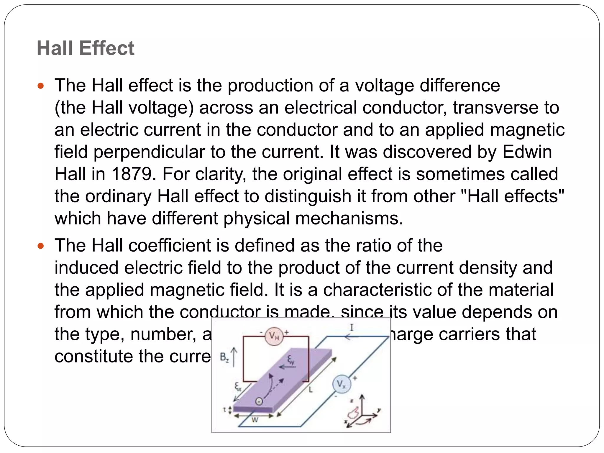
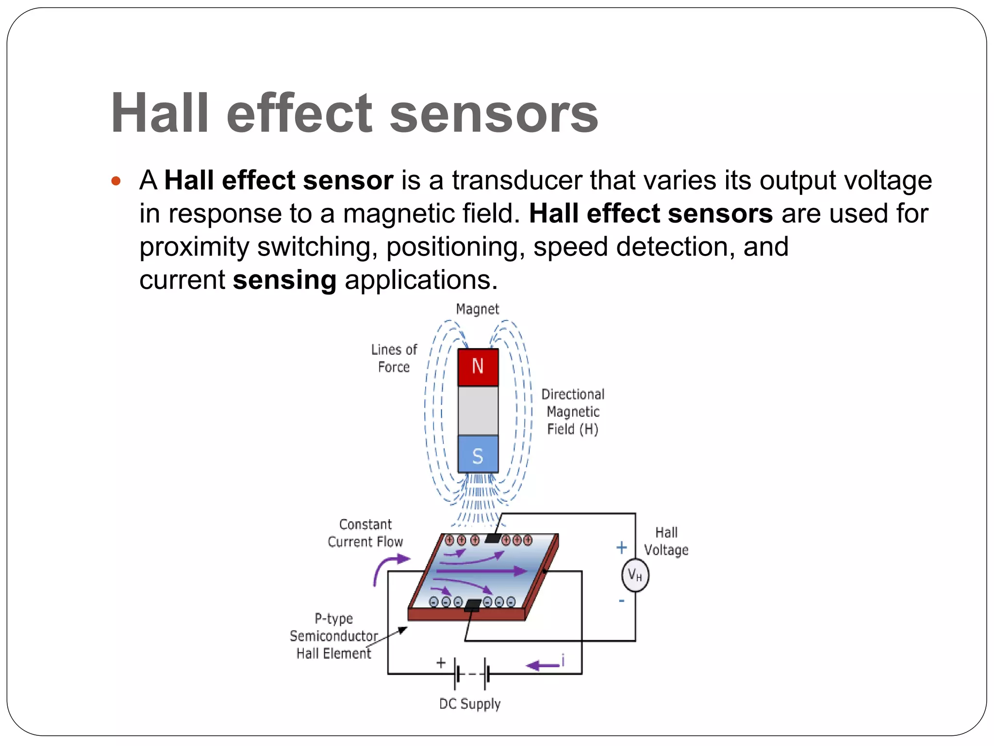
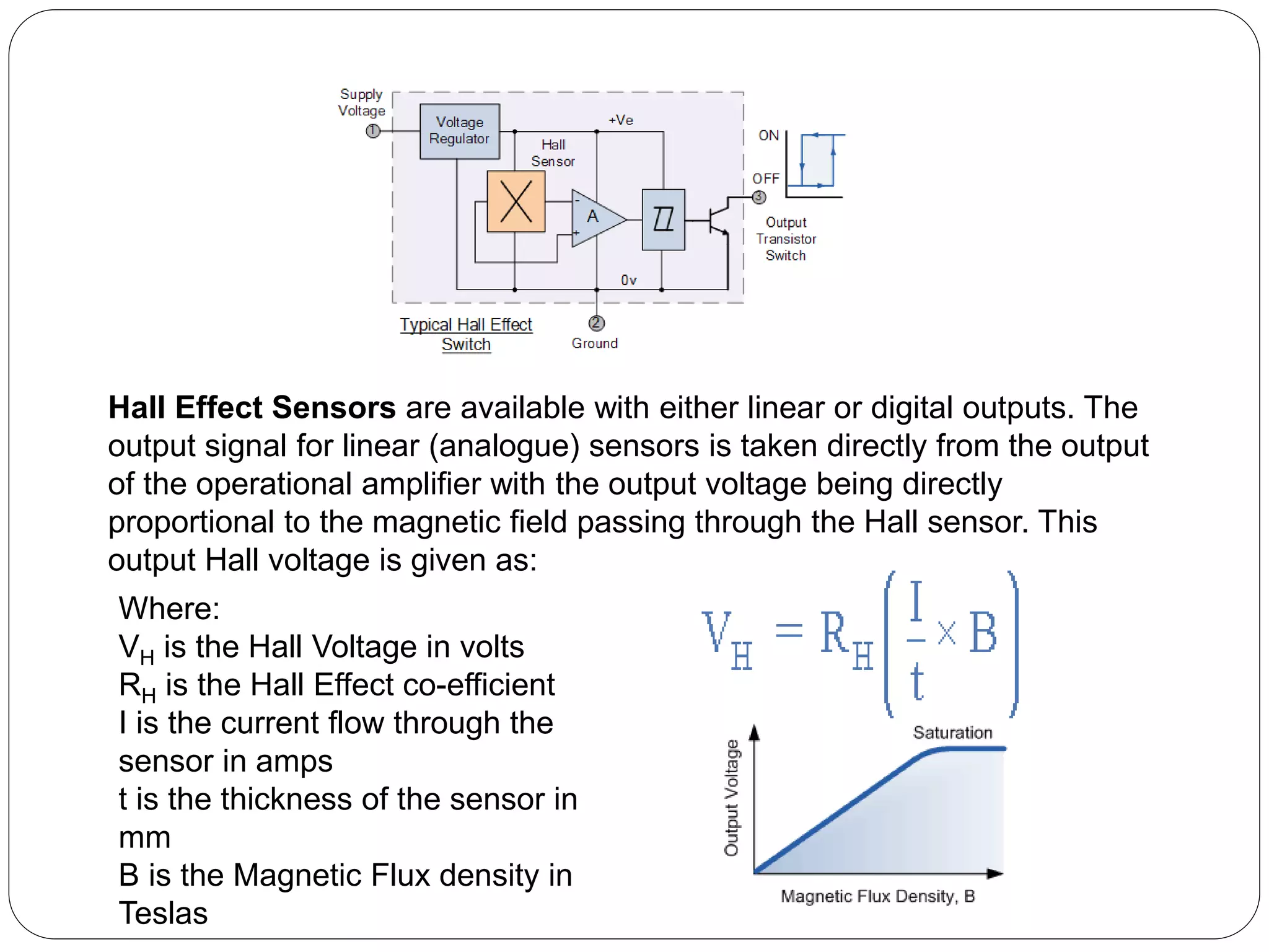
HALL EFFECT SENSOR
Hall Effect
 The Hall effect is the production of a voltage difference
(the Hall voltage) across an electrical conductor, transverse to
an electric current in the conductor and to an applied magnetic
field perpendicular to the current. It was discovered by Edwin
Hall in 1879. For clarity, the original effect is sometimes called
the ordinary Hall effect to distinguish it from other "Hall effects"
which have different physical mechanisms.
 The Hall coefficient is defined as the ratio of the
induced electric field to the product of the current density and
the applied magnetic field. It is a characteristic of the material
from which the conductor is made, since its value depends on
the type, number, and properties of the charge carriers that
constitute the current.
Hall effect sensors
 A Hall effect sensor is a transducer that varies its output voltage
in response to a magnetic field. Hall effect sensors are used for
proximity switching, positioning, speed detection, and
current sensing applications.
Working Principle
 Hall Effect Sensors consist basically of a thin piece of rectangular p-type
semiconductor material such as gallium arsenide (GaAs), indium antimonide
(InSb) or indium arsenide (InAs) passing a continuous current through itself. When
the device is placed within a magnetic field, the magnetic flux lines exert a force on
the semiconductor material which deflects the charge carriers, electrons and
holes, to either side of the semiconductor slab. This movement of charge carriers
is a result of the magnetic force they experience passing through the
semiconductor material.
 As these electrons and holes move side wards a potential difference is produced
between the two sides of the semiconductor material by the build-up of these
charge carriers. Then the movement of electrons through the semiconductor
material is affected by the presence of an external magnetic field which is at right
angles to it and this effect is greater in a flat rectangular shaped material.
 The effect of generating a measurable voltage by using a magnetic field is called
the Hall Effect after Edwin Hall who discovered it back in the 1870’s with the basic
physical principle underlying the Hall effect being Lorentz force. To generate a
potential difference across the device the magnetic flux lines must be
perpendicular, (90o) to the flow of current and be of the correct polarity, generally a
south pole.
 The Hall effect provides information regarding the type of magnetic pole and
magnitude of the magnetic field. For example, a south pole would cause the
device to produce a voltage output while a north pole would have no effect.
Generally, Hall Effect sensors and switches are designed to be in the “OFF”, (open
Hall Effect Sensors are available with either linear or digital outputs. The
output signal for linear (analogue) sensors is taken directly from the output
of the operational amplifier with the output voltage being directly
proportional to the magnetic field passing through the Hall sensor. This
output Hall voltage is given as:
Where:
VH is the Hall Voltage in volts
RH is the Hall Effect co-efficient
I is the current flow through the
sensor in amps
t is the thickness of the sensor in
mm
B is the Magnetic Flux density in
Teslas
Hall Effect Applications
 Hall effect sensors are activated by a magnetic field and in
many applications the device can be operated by a single
permanent magnet attached to a moving shaft or device.
There are many different types of magnet movements, such
as “Head-on”, “Sideways”, “Push-pull” or “Push-push” etc
sensing movements. Which every type of configuration is
used, to ensure maximum sensitivity the magnetic lines of flux
must always be perpendicular to the sensing area of the
device and must be of the correct polarity.
 Also to ensure linearity, high field strength magnets are
required that produce a large change in field strength for the
required movement. There are several possible paths of
motion for detecting a magnetic field, and below are two of the
more common sensing configurations using a single
magnet: Head-on Detection and Sideways Detection.
Advantage of hall effect:-
The advantages of using Hall Effect sensors are as follows:
 Production of an output voltage signal independent of the rate of the
detected field.
 Hall Effect sensors are not affected by ambient conditions, such as
dust, humidity, and vibrations and are due to are insensitive to some
ambient conditions based on the principle that these sensors display
a constant flow of an electrical current making their characteristics
constant over time.
 Hall Effect sensors do not have contact with neighboring mechanical
parts, making these sensors strong and sensitive enough to detect
movement. These sensors do not wear over time thus maintain
quality and unlimited use.
 Hall Effect sensors are built from semiconductor material that display
low carrier density, hence conductivity is smaller and their voltage is
larger.
 Hall Effect sensors depends on carrier mobility, which eliminates any
perturbations due to surface elements; thus, making these
conductors reproducible and highly reliable.
Disadvantage of hall effect:-
 The Hall Effect sensor does have its disadvantages:
 The Hall Effect sensor is not capable of measuring a current flow at a
distance greater than 10 cm; however, use of a magnet strong
enough to generate a magnetic field wide enough may make this
possible.
 Hall Effect sensors work on the principle of a magnetic field, making
it possible for external magnetic fields to interfere with this and bias
the measurement of a current flow.
 Temperature affects the electrical resistance of the element and the
mobility of majority carriers and also the sensitivity of Hall Effect
sensors.
 Even with well-centered electrodes, the offset voltage still presents
as an output voltage in the absence of a magnetic field.
 An offset voltage occurs when there are physical inaccuracies and
material non-uniformities. It can be as high as 100 mV for a 12V
source. To solve this problem, an additional control electrode would
need to be added and through this a necessary current can be
injected to obtain a null output when no magnetic field is present.
Applications of Hall Effect Sensors
Hall Effect sensors are considered as magnetic sensors with a wide
range of applications. Some of the most popular and effective ways
of utilizing Hall effect sensing devices are listed below for both
analog and digital output sensors.
 Analog output sensor applications include:
 Current sensing
 Variable speed drives
 Motor control protection/indicators
 Power supply sensing
 Motion sensing
 Diaphragm pressure gage
 Flow meters
 Direct current electricity
 Encoded switches
 Rotary encoders
Digital output sensor applications include:
 Wireless communication
 Pressure sensors
 Proximity sensors
 Flow sensors
 Valve position sensors
 Lens position sensors
 Shaft position sensors
Summary
 Hall Effect sensors were developed in 1950, and have come a long
way to become a major requirement for several industrial and
automotive applications.
References
 Hall Effect Sensing and Application, Honeywell.
 Hall Effect Sensors and Magneto resistance, University of Dayton.
 Handbook of Modern Sensors, Physics, Designs and Applications,
Springer Verlag.
 Santini, A. (2013). Automotive Electricity and Electronics. 2nd ed.
New York: Delmar, Cengage learning. 161-164.
 Ramsden, E. (2006). Hall-Effect Sensors. Theory and Application.
2nd ed. Oxford, UK: Elsevier. 1-9.
 Boll, R., Overshott, K.J. (1989). Magnetic Sensors. Volume 5. New
York (USA): VCH Publishers Inc. 46-48.
THANK YOU

hall effect and hall effect sensor

  • 1.
  • 2.
    Hall Effect  TheHall effect is the production of a voltage difference (the Hall voltage) across an electrical conductor, transverse to an electric current in the conductor and to an applied magnetic field perpendicular to the current. It was discovered by Edwin Hall in 1879. For clarity, the original effect is sometimes called the ordinary Hall effect to distinguish it from other "Hall effects" which have different physical mechanisms.  The Hall coefficient is defined as the ratio of the induced electric field to the product of the current density and the applied magnetic field. It is a characteristic of the material from which the conductor is made, since its value depends on the type, number, and properties of the charge carriers that constitute the current.
  • 3.
    Hall effect sensors A Hall effect sensor is a transducer that varies its output voltage in response to a magnetic field. Hall effect sensors are used for proximity switching, positioning, speed detection, and current sensing applications.
  • 4.
    Working Principle  HallEffect Sensors consist basically of a thin piece of rectangular p-type semiconductor material such as gallium arsenide (GaAs), indium antimonide (InSb) or indium arsenide (InAs) passing a continuous current through itself. When the device is placed within a magnetic field, the magnetic flux lines exert a force on the semiconductor material which deflects the charge carriers, electrons and holes, to either side of the semiconductor slab. This movement of charge carriers is a result of the magnetic force they experience passing through the semiconductor material.  As these electrons and holes move side wards a potential difference is produced between the two sides of the semiconductor material by the build-up of these charge carriers. Then the movement of electrons through the semiconductor material is affected by the presence of an external magnetic field which is at right angles to it and this effect is greater in a flat rectangular shaped material.  The effect of generating a measurable voltage by using a magnetic field is called the Hall Effect after Edwin Hall who discovered it back in the 1870’s with the basic physical principle underlying the Hall effect being Lorentz force. To generate a potential difference across the device the magnetic flux lines must be perpendicular, (90o) to the flow of current and be of the correct polarity, generally a south pole.  The Hall effect provides information regarding the type of magnetic pole and magnitude of the magnetic field. For example, a south pole would cause the device to produce a voltage output while a north pole would have no effect. Generally, Hall Effect sensors and switches are designed to be in the “OFF”, (open
  • 5.
    Hall Effect Sensorsare available with either linear or digital outputs. The output signal for linear (analogue) sensors is taken directly from the output of the operational amplifier with the output voltage being directly proportional to the magnetic field passing through the Hall sensor. This output Hall voltage is given as: Where: VH is the Hall Voltage in volts RH is the Hall Effect co-efficient I is the current flow through the sensor in amps t is the thickness of the sensor in mm B is the Magnetic Flux density in Teslas
  • 7.
    Hall Effect Applications Hall effect sensors are activated by a magnetic field and in many applications the device can be operated by a single permanent magnet attached to a moving shaft or device. There are many different types of magnet movements, such as “Head-on”, “Sideways”, “Push-pull” or “Push-push” etc sensing movements. Which every type of configuration is used, to ensure maximum sensitivity the magnetic lines of flux must always be perpendicular to the sensing area of the device and must be of the correct polarity.  Also to ensure linearity, high field strength magnets are required that produce a large change in field strength for the required movement. There are several possible paths of motion for detecting a magnetic field, and below are two of the more common sensing configurations using a single magnet: Head-on Detection and Sideways Detection.
  • 8.
    Advantage of halleffect:- The advantages of using Hall Effect sensors are as follows:  Production of an output voltage signal independent of the rate of the detected field.  Hall Effect sensors are not affected by ambient conditions, such as dust, humidity, and vibrations and are due to are insensitive to some ambient conditions based on the principle that these sensors display a constant flow of an electrical current making their characteristics constant over time.  Hall Effect sensors do not have contact with neighboring mechanical parts, making these sensors strong and sensitive enough to detect movement. These sensors do not wear over time thus maintain quality and unlimited use.  Hall Effect sensors are built from semiconductor material that display low carrier density, hence conductivity is smaller and their voltage is larger.  Hall Effect sensors depends on carrier mobility, which eliminates any perturbations due to surface elements; thus, making these conductors reproducible and highly reliable.
  • 9.
    Disadvantage of halleffect:-  The Hall Effect sensor does have its disadvantages:  The Hall Effect sensor is not capable of measuring a current flow at a distance greater than 10 cm; however, use of a magnet strong enough to generate a magnetic field wide enough may make this possible.  Hall Effect sensors work on the principle of a magnetic field, making it possible for external magnetic fields to interfere with this and bias the measurement of a current flow.  Temperature affects the electrical resistance of the element and the mobility of majority carriers and also the sensitivity of Hall Effect sensors.  Even with well-centered electrodes, the offset voltage still presents as an output voltage in the absence of a magnetic field.  An offset voltage occurs when there are physical inaccuracies and material non-uniformities. It can be as high as 100 mV for a 12V source. To solve this problem, an additional control electrode would need to be added and through this a necessary current can be injected to obtain a null output when no magnetic field is present.
  • 10.
    Applications of HallEffect Sensors Hall Effect sensors are considered as magnetic sensors with a wide range of applications. Some of the most popular and effective ways of utilizing Hall effect sensing devices are listed below for both analog and digital output sensors.  Analog output sensor applications include:  Current sensing  Variable speed drives  Motor control protection/indicators  Power supply sensing  Motion sensing  Diaphragm pressure gage  Flow meters  Direct current electricity  Encoded switches  Rotary encoders
  • 11.
    Digital output sensorapplications include:  Wireless communication  Pressure sensors  Proximity sensors  Flow sensors  Valve position sensors  Lens position sensors  Shaft position sensors Summary  Hall Effect sensors were developed in 1950, and have come a long way to become a major requirement for several industrial and automotive applications.
  • 12.
    References  Hall EffectSensing and Application, Honeywell.  Hall Effect Sensors and Magneto resistance, University of Dayton.  Handbook of Modern Sensors, Physics, Designs and Applications, Springer Verlag.  Santini, A. (2013). Automotive Electricity and Electronics. 2nd ed. New York: Delmar, Cengage learning. 161-164.  Ramsden, E. (2006). Hall-Effect Sensors. Theory and Application. 2nd ed. Oxford, UK: Elsevier. 1-9.  Boll, R., Overshott, K.J. (1989). Magnetic Sensors. Volume 5. New York (USA): VCH Publishers Inc. 46-48.
  • 13.