Download as PDF, PPTX

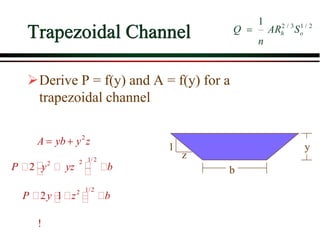
![Robert –Manning improved Work
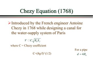
Upon Chezy’s Equation and gave:
V(m/s)=1/n[Rh]^(2/3) S^(1/2)
V(ft/s)=1.486/n [Rh]^(2/3) S^(1/2)
These are emprical formulas
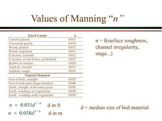
Where “n” is manning co-efficent](https://image.slidesharecdn.com/openchannelflow-151014223518-lva1-app6891/85/Open-channel-flow-5-320.jpg)
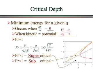
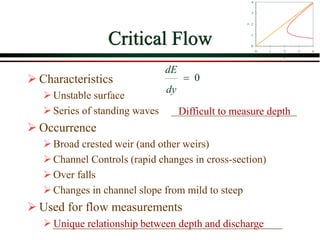
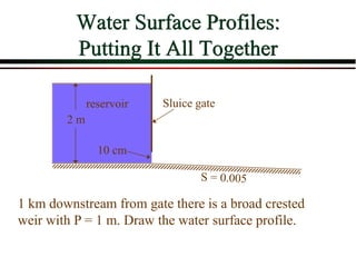
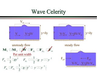
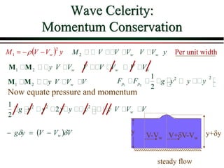
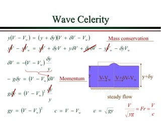
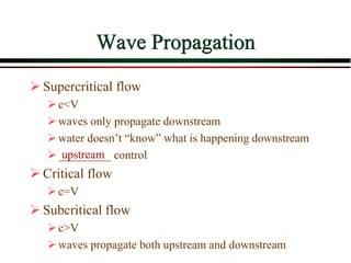


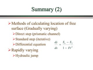
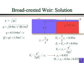
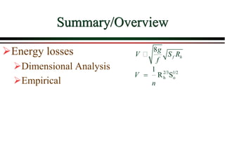
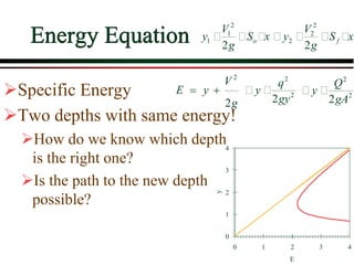
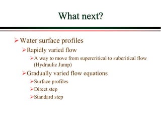
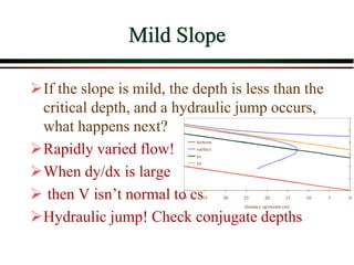
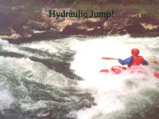


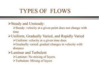
This document discusses open channel flow, including: 1) Key parameters like hydraulic radius, channel roughness, and types of flow profiles. 2) Empirical equations for open channel flow including Chezy and Manning's equations. 3) Concepts of critical flow including critical depth, specific energy, and the importance of the Froude number. 4) Measurement techniques for discharge like weirs and sluice gates. 5) Gradually and rapidly varied flow, water surface profiles, and hydraulic jumps.


![General Formulation of Best Hydraulic Channel Section [Naeem Rezghi]](https://cdn.slidesharecdn.com/ss_thumbnails/presentation-130215113843-phpapp01-thumbnail.jpg?width=640&height=640&fit=bounds)


![11. Silt Theories [Lacey's Theory].pdf](https://cdn.slidesharecdn.com/ss_thumbnails/11-230714062706-5eed0a09-thumbnail.jpg?width=640&height=640&fit=bounds)


