Micro stepping mode for stepper motor
•Download as PPTX, PDF•
2 likes•3,781 views

MICRO STEPPING MODE FOR STEPPER MOTOR

Recommended
More Related Content
What's hot
What's hot (20)
Viewers also liked
Viewers also liked (20)
Similar to Micro stepping mode for stepper motor
Similar to Micro stepping mode for stepper motor (20)
More from Swathi Venugopal
More from Swathi Venugopal (6)
Recently uploaded
Recently uploaded (20)
Micro stepping mode for stepper motor
- 1. MICRO STEPPING MODE FOR STEPPER MOTOR
- 2. OVERVIEW • INTRODUCTION • OPERATION • TYPES OF STEPPER MOTOR • MODES OF OPERATION • MICRO STEPPING MODE • DRIVER OVERVIEW • MICRO STEPPING CONTROL SYSTEM • EXPERIMENTAL RESULTS • CONCLUSION • REFERENCE
- 3. INTRODUCTION Stepper Motor “A stepper motor (or step motor) is a brushless, synchronous electric motor that can divide a full rotation into a large number of steps” Multiple "toothed" electromagnets arranged around a central gear-shaped piece of iron. The electromagnets are energized by an external control circuit, such as (eg;microcontroller )
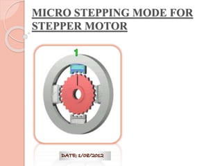
- 4. Internal components of a stepper motor Rotor Stator Coils 2 1 S 1 N 2 Outside Casing Stator Rotor
- 5. Step angle θs “Step angle of the stepper motor is defined as the angle traversed by the motor in one step.” θs=360/S s=m*N m= no of phases N=no of rotor teeth
- 6. OPERATION Basic stepper motor operation
- 7. TYPES OF STEPPER MOTOR 1 Variable reluctance 2 Permanent magnet 3 Hybrid
- 8. CHARACTERISTICS Constant power devices. Speed increases, torque decreases. Steppers exhibit more vibration than other motor types, as the discrete step tends to snap the rotor from one position to another (called a detent). “Ringing" effect can be mitigated by accelerating quickly using a micro-stepping driver.
- 9. ADVANTAGES & DISADVANTAGES ADVANTAGES DISADVANTAGES • High accuracy of motion • High vibration levels due to stepwise motion • Easily adaptable to digital control applications •Dynamic instability, low frequency oscillations around Fs non linear assembly of the control system • No stability problem ----------------------------------- • Response can be controlled by electronic switching -----------------------------------
- 10. MODES OF OPERATION Half Step Operation Full Step Operation TwSoin-Cgloei-lC eoxilc eixtactitioatnion Micro stepping
- 11. MICRO STEPPING MODE “An electronic control technique that proportions the current in a step motor’s windings to provide additional intermediate positions between poles.” Produces smooth rotation over a wide speed range and high positional resolution. It allows even smaller steps by using different currents through the two motor windings.
- 12. h = ( a2 + b2 )0.5 x = ( S / (π / 2) ) arctan( b / a ) a -- torque applied by winding with equilibrium at 0 radians. b -- torque applied by winding with equilibrium at S radians. h -- holding torque of composite. x -- equilibrium position, in radians. S -- step angle, in radians.
- 13. Sine cosine microstepping a= h1 sin((( π/2)/s)θ)) h1 = single winding holding current ((( π/2)/s)θ))=electric shaft angle b= h1 cos((( π/2)/s)θ)) To hold motor rotor to angle θ Ia= current through winding with equilibrium at angle 0’ Ib= current through winding with equilibrium at angle S’ Ia=Imax sin((( π/2)/s)θ)) Ib=Imax cos((( π/2)/s)θ)) MA=KM*Ia=Imax sin((( π/2)/s)θ)) MB=KM*Ib=Imax sin((( π/2)/s)θ)) Mo=KM*Imax
- 14. Example 1
- 15. Example 2
- 16. DRIVER OVERVIEW USER INTERFACE INDEXE R DRIVER MOTO R HIGH LEVEL COMMANDS STEP PULSES MOTOR CURRENT
- 17. Stepper motor with drive circuit “Stepper motor performance is strongly dependent on the drive circuit”
- 18. MICRO STEPPING CONTROL SYSTEM Block diagram
- 19. Electronic scheme of digital command block
- 21. 1 Resonance are significantly reduced 11 Noise generation is considerably reduced 111 Precise position control 1V Very high step resolution
- 22. CONCLUSION • Experimental results prove that a smooth and continuous rotation is achieved. • Velocity ripples are eliminated. • Greatly improves performance at low rotational speeds and helps avoid resonance problems. • The method is found to be less complex and cheap also
- 23. REFERENCES [1] P. Acarnley, Stepping Motors: a Guide to Modern Theory and Practice, 4th ed., IEE Control Engineering Series 63, ISBN: 0-85296-029-8, Michael Faraday House, 2002, pp.48-5 1. [2] T. Kenjo and A. Sugawara, Stepping Motors and Microprocessor Control, 2nd ed., ISBN:0-19-859385-6, Oxford: Clarendon Press, 2003, pp.113-120. [3] H. Maczala, Elektrische Kleinmotoren, ISBN: 3-8169-0909-4, Expert Verlag, 1993, pp.261-263. [4] Gh. Baluta., Electrical Drives with Stepper Motors (in Romanian), ISBN:973- 621-034-0, Iasi: Gh. Asachi, 2003, pp.63-85. [5] Gh. Baluta, Low Power Electrical Drives. Applications (in Romanian), IS.B.N: 973-621-072-3, Iasi: Politehnium, 2004, pp.40-48.
- 24. THANK YOU