1. The Babcock & Wilcox Company
Chapter 25
Boiler Auxiliaries
A variety of auxiliary components are needed for initial opening at the upstream static pressure set
the modern steam generating system to function ef- point and for maximum discharge capacity at 3%
fectively and efficiently. While space prevents an in- above set point pressure.1
depth review of all items, several deserve special at- Fig. 2 shows a typical power actuated type safety
tention. Safety and relief valves are critical to assure valve that may be used in some Code approved appli-
the continued safe operation of the boiler. The inter- cations. Power actuated valves are fully opened at the
play of dampers, stack design, and fans ensures set point pressure by a controller with a source of power
proper air and gas flow for optimum combustion. Fi- such as air, electricity, hydraulic fluid, or steam.
nally, a specialty condenser is used to supply high Fig. 3 shows a typical spring loaded relief valve for
purity water for attemperator spray in industrial boil- liquid service designed for a small initial opening at
ers where such water is not typically available. the upstream static pressure set point. The valve will
Safety and relief valves
The most critical valve on a boiler is the safety valve.
Its purpose is to limit the internal boiler pressure to a
point below its safe operating level. To accomplish this
goal, one or more safety valves must be installed in
an approved manner on the boiler pressure parts so
that they can not be isolated from the steam space.
The valves must be set to activate at approved set point
pressures (discussed below) and then close when the
pressure drops below the set point. When open, the set
of safety valves must be capable of carrying all of the
steam which the boiler is capable of generating with-
out exceeding the specified pressure rise.
The American Society of Mechanical Engineers
(ASME) Boiler and Pressure Vessel Code, Section I,
outlines the minimum requirements for safety and
safety relief valves applying to new stationary water
tube power boilers. The Code also covers requirements
for safety and safety relief valves for other applica-
tions beyond the scope of this text. By Code definition,
a safety valve is used for gas or vapor service, a relief
valve is used primarily for liquid service, and a safety
relief valve may be suitable for use as either a safety
or a relief valve.1
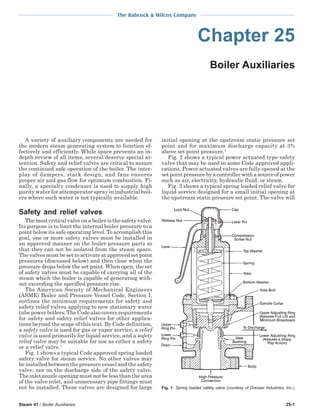
Fig. 1 shows a typical Code approved spring loaded
safety valve for steam service. No other valves may
be installed between the pressure vessel and the safety
valve, nor on the discharge side of the safety valve.
The inlet nozzle opening must not be less than the area
of the valve inlet, and unnecessary pipe fittings must
not be installed. These valves are designed for large Fig. 1 Spring loaded safety valve (courtesy of Dresser Industries, Inc.).
Steam 41 / Boiler Auxiliaries 25-1
2. The Babcock & Wilcox Company
modified existing boilers or new boilers installed in
parallel with old boilers, or boilers operated at an ini-
tial low pressure but designed for future high pres-
sure (increases or decreases in operating pressure).
Additional requirements, including mounting, opera-
tion, mechanical, material, inspection and testing of
safety and safety relief valves are specified in the Code.
Code requirements for once-through boilers
For safety valve requirements on once-through
boilers, the Code allows a choice of using the rules for
a drum boiler or special rules for once-through boil-
ers. Power operated valves may be used as Code re-
quired valves to account for up to 30% of the total re-
quired relief valve capacity. If the power relief valve
discharges to an intermediate pressure (not atmo-
spheric), the valve does not have to be capacity certi-
fied, but it must be marked with the design capacity
at the specified relieving conditions. However, it is
important to remember that, in order for a power re-
lief valve discharging to an intermediate pressure to
be counted as part of the required safety valve reliev-
ing capacity, the intermediate pressure zone must be
fully protected with its own relieving capacity.
The power relief valve must be in direct communi-
cation with the boiler, and its controls must be part of
the plant’s essential service network, including re-
quired pressure recording instruments. A special iso-
Fig. 2 Typical power actuated safety valve (courtesy of Dresser
Industries, Inc.).
continue to open as pressure increases above set point
pressure to prevent additional pressure rise.
Because of variations in power boiler designs, Code
interpretations are sometimes necessary. It is also nec-
essary to comply with local ordinances. The owner’s
approval must be obtained for all safety valve settings.
For drum boilers with superheaters, The Babcock
& Wilcox Company (B&W) follows the Code procedure
in which the safety valves are set such that the su-
perheater valve(s) lift first at all loads. This maintains
a flow of steam through the superheater(s) to provide
a measure of overheat protection. This method per-
mits the piping and valves downstream of the super-
heater to be designed for a lower pressure than other
methods. This method is required on hand controlled
units, stoker or other fuel-bed-fired units, and brick
set units. Another method may be used for all other
types of boilers that permits the drum safety valves to
lift first. This method could allow a reduced flow condi-
tion to occur in the superheater while the boiler is still
at a high heat input level. As a result, some superheater
materials can exceed temperature limits.
The required valve relieving capacities for waste
heat boiler applications are determined by the manu-
facturer. Auxiliary firing must be considered in the
selection of safety or safety relief valves. The Code
required relieving capacity must be based on the
maximum boiler output capabilities by waste heat
recovery, auxiliary firing, or the combination of waste
heat recovery with auxiliary firing.1 Fig. 3 Spring loaded pressure relief valve (courtesy of Crosby Valve
Additional Code requirements are applicable for & Gage Company).
25-2 Steam 41 / Boiler Auxiliaries
3. The Babcock & Wilcox Company
lating stop valve may be installed for power relief located in a rigid frame. They are generally rectan-
valve maintenance provided redundant relieving ca- gular in shape. One blade shaft end extends far
pacity is installed. Provided all the Code requirements enough beyond the frame so that a drive can be
are met or exceeded, the remaining required relief ca- mounted for damper operation. Ideally, blade shape
pacity is met with spring loaded valves set at 17% is determined by the amount of pressure drop that can
above master stamping pressure. The superheater be tolerated across the open damper. In reality, it is
division valves (Chapter 19) are part of the power usually a compromise among the following design
relief valve system so that credit may be taken for the goals: the ideal shape required for minimizing pres-
spring loaded superheater outlet valve(s) relieving sure drop, the ideal shape for minimizing initial cost,
capacity as part of the total required relieving capac- and the ideal shape to attain the required structural
ity. With a superheater division valve, the code requires strength to withstand pressure and temperature con-
6 lb/h relieving capacity per each square foot of su- ditions. An unreinforced flat plate is the simplest shape
perheater heating surface (0.008 kg/s per m2). The but is relatively weak and offers the greatest pressure
blowdown of the spring loaded valves shall not be less drop. Air foil shaped blades have lower pressure losses
than 8% nor more than 10% of set pressure. (See and have somewhat greater strength. If uniform down-
Code, Section 1.)1 stream flow distribution is required, opposed blade ro-
tation is used; otherwise, parallel blade rotation may
be used. (See Fig. 5.)
Air and flue gas dampers If the louver damper is to be used for isolation pur-
Dampers are used to control flow and temperature poses, thin, flexible metallic seal strips are mounted
of air and flue gas. They can also be used to isolate on the blades to minimize leakage around the closed
equipment in the air or flue gas streams when such blades. Seal strips are not required in applications
equipment is out of service or requires maintenance. where louver dampers are used for flow control.
The Air Movement and Control Association in Pub- Depending on the application, louver dampers may
lication 850-02, Application and Specification Guide have internal or external bearings. External bearings
for Flue Gas Isolation and Control Dampers, defines are of the self-aligning and self-lubricating ball or
both the isolation and control functions for the selec- sleeve type, which require a mounting block and pack-
tion of dampers.2 ing gland. In extreme conditions, packing glands may
Isolation dampers may be the nominal shutoff or have a seal air provision. Internal bearings are ma-
zero leakage type. Shutoff dampers are used in ap- chined castings with a self-cleaning feature. These
plications where some limited leakage is tolerable. All types of bearings do not require lubrication and elimi-
types of dampers, with appropriate blade seals, can
be used. Zero leakage dampers are designed to pre-
vent any flow media leakage past the closed damper. Damper
Frame
This is accomplished by overpressurizing the blade
seal periphery with seal air, which leaks back into the
system. Guillotine-type dampers are best suited for
this service. A pair of dampers or pairs of blades within
one damper with an overpressurized air block between
them can also be used. In heat recovery steam gen-
erator (HRSG) applications, diverter dampers are of-
ten used along with stack cap dampers to assist in Actuator
maintaining boiler temperature during overnight
shutdowns.
Control dampers are capable of providing a variable
restriction to flow and may be of several varieties.2
Balancing dampers are used to balance flow in two Bearing
or more ducts. Preset position dampers are normally
open or normally closed dampers which move to an
adjustable preset position on a signal. Modulating Shaft
dampers are designed to assume any position between Linkage
fully open and fully closed in response to a varied sig-
nal (either pneumatic or electric). A positioner with
feedback indication is normally required.2
Dampers may also be classified by shape or configu- Packing Box
ration. Damper shape classifications that are commonly
used in the fossil fuel-fired steam generation industry
are louver, round (or wafer) and guillotine (or slidegate).
Louver dampers Airfoil
Blade
A louver damper, as shown in Fig. 4, is character- Fig. 4 Opposed-blade louver damper (adapted from Mader Damper
ized by one or more blades that mount into bearings Co.).
Steam 41 / Boiler Auxiliaries 25-3
4. The Babcock & Wilcox Company
Housing Blade
Fig. 5 Louver damper blade arrangement options (courtesy of Air
Movement and Control Association, Inc.).
nate the need for the damper shaft to penetrate the
frame, eliminating the maintenance associated with Bar Stop Seal
shaft seals.
Operator Mount Operator
Fig. 7 Two-bladed wafer damper.
Round or wafer dampers
Round dampers, as shown in Fig. 6, can be used
for control or shutoff service. Due to higher allowable shown in Fig. 8, the blade edge extends through the
velocity limits, they are usually smaller than louver frame into a seal chamber that is pressurized by a seal
dampers and have a smaller seal edge to area ratio, air blower. Seals for this type of damper are normally
which makes them more efficient for shutoff applica- designed to eliminate reverse flexing. The blade is
tions. They can also be configured in a two or more actuated by a chain and sprocket, pneumatic cylin-
blade configuration with opposed operation for flow der, hydraulic cylinder, or screw-type mechanism, con-
control as shown in Fig. 7, although this arrangement nected to a drive which is mounted on the frame.
tends to reduce sealing efficiency. Guillotines are typically large and used for isolation ser-
vice, preferably in horizontal ducts. It is not uncommon
for blade thickness to reach 0.75 in. (19 mm), and blade
Guillotine or slidegate dampers thicknesses exceeding 1 in. (25.4 mm) have been used.
Guillotine dampers have an external frame and
drive system that can insert and withdraw the blade
which acts as a blanking plate in the full cross-sec-
tion of the duct. This minimizes the sealing edge re-
quired for any given duct size. The blade periphery is
surrounded by, and forced between, flexible metal
sealing strips. On zero leakage dampers, such as
Fig. 6 Wedge seat round damper (courtesy of Damper Design, Inc.). Fig. 8 Guillotine damper (courtesy of Effox, Inc.).
25-4 Steam 41 / Boiler Auxiliaries
5. The Babcock & Wilcox Company
Expansion joints A metallic expansion joint can accept toggle and
axial motion but is unable to accept significant shear
Expansion joints are used in duct systems, wind- motion. For that reason, whenever two components
boxes, and other areas of the boiler and air quality must be connected that are displacing relative to one
control system islands to allow for relative movement another in a shear plane, two metallic expansion joints
between components of a system. This relative move- must be employed by placing them at opposite ends
ment is usually caused by thermal expansion and con- of a duct toggle section as shown in Fig. 9. A metallic
traction. Expansion joints are available in various joint has a pinned support connection which defines
configurations and can feature flow liners and insu- its toggle axis. Side pins are used to transmit gravity
lation pillows to allow for a wide range of temperature loads across a joint and may pass through either round
and dust conditions. They are generally of metal con- or slotted holes. Center pins may also be used to trans-
struction or constructed of elastomers and composite mit loads of pressure and to actuate another expan-
materials, and are designed for maximum flexibility sion joint in series.
under the required service conditions. Nonmetallic joints (Fig. 10) are able to accept shear
The most common configuration for a metallic ex- (three-way) motion, which is their primary advantage
pansion joint is the multi-leaf or box fold joint. (See over metallic joints. For this reason, nonmetallic joints
Fig. 9.) The box fold is normally external but can be do not require a toggle section and only one joint is
internal if space considerations require. However, if required for most applications. Nonmetallic joints are
an internal fold is used, the additional pressure drop made with reinforced elastomers or Teflon coated wo-
caused by the flow area restriction must be accounted ven fiberglass, and are normally the plain flat belt
for when sizing the draft equipment. Also, internal type. Flanged or U-type joints are also available. If
folds could be subject to erosion damage in a dirty gas design temperatures are above the use limit of the belt
environment. If the external fold expansion joint is material, composite belts with an insulation liner are
placed in a dirty environment, the folds are packed used and may include an insulation pillow for the
(intermediate temperature fiberglass insulating block higher temperatures.
is a typical packing) and the packed folds are shielded, It is essential that all relative motions between com-
typically with 10 gauge sheet of the same class mate- ponents be completely accounted for when designing
rial as the duct. Hinged shields are often used to per-
mit field packing of the joint folds. The extent and
location of packing and shielding are dictated by the
joint designer’s field experience. Nonmetallic joints also Bolt and Washer
require packing and shielding as dictated by the Retainer Bar
designer’s field experience.
Pin Adjustable
Slot Flange
Breach
Opening
Adjustable
Flange
Pressure
Load
Flow
Duct 2
Toggle
Section
Duct 1
Fig. 9 Multi-leaf metallic expansion joint with pinned support connection. Fig. 10 Nonmetallic expansion joint.
Steam 41 / Boiler Auxiliaries 25-5
6. The Babcock & Wilcox Company
the connecting expansion joint, and that design pres- where
sures and temperatures appropriate for the type of ser-
Ptotal = total pressure, lb/ft2 (N/m2 )
vice be used for material and thickness selection. Fail-
Ps = static pressure, lb/ft2 (N/m2 )
ure to do so can result in premature failure of the ex-
Pv = velocity pressure, lb/ft2 (N/m2 ) = V 2/2gcv
pansion joint.
V = average gas velocity
v = specific volume of the gas
Stacks and draft gc = conversion constant
= 32.17 lbm ft/lbf s2 = 1 kgm/Ns2
An adequate flow of air and combustion gases is
required for the complete and effective combustion of
fossil and chemical fuels. Flow is created and sustained Stack effect
by stacks and fans. Either the stack alone, or a com-
bination of stack and fans, produces the required pres- Stack effect (SE), or chimney action, is the differ-
sure head to generate the required flow. ence in pressure caused by the difference in elevation
between two locations in vertical ducts or passages
Draft is the difference between atmospheric pres- conveying heated gases at zero gas flow. It is caused
sure and the static pressure of combustion gases in a by the difference in density between air and heated
furnace, gas passage, flue or stack. The flow of gases gases, whether air or flue gas. The stack effect is in-
through the boiler can be achieved by four methods dependent of gas flow and can not be measured with
of creating draft, referred to as forced draft, induced draft gauges. Draft gauges combine stack effect and
draft, balanced draft and natural draft. flow losses. The intensity and distribution of this pres-
Forced draft boilers operate with the air and com- sure difference depends on the height, the arrange-
bustion products (flue gas) maintained above atmo- ment of ducts, and the average gas temperature in the
spheric pressure. Fans at the inlet to the boiler sys- duct and ambient air temperature.
tem provide sufficient pressure to force the air and flue Based upon this definition, the overall stack effect
gas through the system. Any openings in the boiler in its most general form is defined as:
settings, such as opened doors, allow air or flue gas to
escape unless the opening is also pressurized. g g 1 1
∆PSE = Z ( ρa − ρ g ) = Z −
Induced draft boilers operate with air and gas static gc va vg
gc (2)
pressure below atmospheric. The static pressure is
progressively lower as the gas travels from the air inlet where
to the induced draft fan. The required flow through
the boiler can be achieved by the stack alone when ∆PSE = stack draft effect driving pressure, lb/ft2 (N/
the system pressure loss is low or when the stack is m2)
tall; this is called natural draft. For most modern boil- g = acceleration of gravity = 32.17 ft/s2 (9.8 m/
ers, a fan at the boiler system outlet is needed to draw s2)
flow through the boiler. Unlike forced draft units, air gc = 32.17 lbm ft/lbf s2 (1 kgm/Ns2 )
from the boiler surroundings enters through (infil- Z = elevation between points 1 and 2, ft (m)
trates) any openings in the boiler setting. ρa = density of air at ambient conditions, lb/ft3
(kg/m3)
Balanced draft boilers have a forced draft air fan ρg = average density of flue gas, lb/ft3 (kg/m3)
at the system inlet and an induced draft fan near the va = specific volume of air at ambient conditions,
system outlet. The static pressure is above atmospheric ft3/lb (m3/kg)
at the forced draft fan outlet and decreases to atmo- vg = average specific volume of flue gas, ft3/lb
spheric pressure at some point within the system (typi- (m3/kg)
cally the lower furnace). The static pressure is subat-
mospheric and progressively decreases as the gas trav- The customary English units used for draft calcu-
els from the balance point to the induced draft fan. lations are inches of water for draft pressure loss and
This scheme reduces both flue gas pressure and the feet for stack height or elevation. Using this system of
tendency of hot gases to escape. There are also power units, the incremental stack effect (inches of pressure
savings for this method because forced draft air fans loss per foot of stack height) can be evaluated from:
require smaller volumetric flow rates and therefore
less energy for a given mass flow. Most modern boil- 1 1 1
SE = −
ers are balanced draft for these reasons. va vg 5.2
(3)
Draft loss is the reduction in static pressure of a gas
caused by friction and other nonrecoverable pressure where
losses associated with the gas flow under real condi-
tions. As discussed in Chapter 3, static pressure is re- SE = stack effect, in./ft
lated to the total pressure at a location by the addi-
tion of the velocity or dynamic pressure. For convenience, Table 1 provides the specific vol-
ume of air and flue gas at one atmosphere and 1000R
V2 (556K). Assuming air and flue gas can be treated as
Ptotal = Ps + Pv = Ps + (1) ideal gases, the ideal gas law in Chapter 3 permits
2 g cv calculation of the specific volume at other conditions:
25-6 Steam 41 / Boiler Auxiliaries
7. The Babcock & Wilcox Company
ture. There is also some infiltration of cold air. The total
Table 1 loss in temperature in a stack depends upon the type
Sample Specific Volumes at 1000R (556K) of stack, stack diameter, stack height, gas velocity, and
and One Atmosphere a number of variables influencing the outside stack
vb vb surface temperature. Fig. 11 indicates an approximate
Gas (ft3/lb) (m3/kg) stack exit temperature relative to height, diameter,
and inlet gas temperature.
Dry air 25.2 1.57
Combustion air (0.013 lb
water/lb dry air) 25.4 1.58 Sample stack effect calculation
Flue gas (3% water by wt) 24.3 1.5
Flue gas (5% water by wt) 24.7 1.54 Fig. 12 illustrates the procedure used in calculat-
Flue gas (10% water by wt) 25.7 1.60 ing stack effect. The stack effect can either assist or
resist the gas flow through the unit. The three gas
passages are at different temperatures and the ex-
T BR ample is at sea level. For illustrative purposes, assume
v = vR f (4) atmospheric pressure, i.e., (draft = 0) at point D.
TR B Stack effect always assists up-flowing gas and resists
down-flowing gas. Plus signs are assigned to up flows
where and minus signs to down flows. Using values from Table
v = specific volume at Tf and B, ft3/lb (m3/kg) 3 for an ambient air temperature of 80F (27C), the stack
vR = specific volume at TR and BR, ft3/lb (m3/kg) effect in inches of water for each passage is:
T f = average fluid temperature, R (K) Stack effect C to D = + (110 × 0.0030) = +0.33 in. H2O
= Tf (F) + 460 (Tf (C) + 256) Stack effect B to C = − (100 × 0.0087) = −0.87 in. H2O
B = barometric pressure (see Table 2), in. Hg Stack effect A to B = + (50 × 0.0100) = +0.50 in. H2O
(kPa)
TR = 1000R (556K)
BR = 30 in. Hg (101.6 kPa)
Table 3 provides a reference set of values for SE at
one atmosphere. The total theoretical draft effect of a
stack or duct at a given elevation above sea level can
be calculated from Equation 1 or from:
B
Stack draft = Z ( SE ) elevation (5)
Bsea level
where
Z = stack height, ft (m)
SE = stack effect, in./ft (Table 3 or Equation 2)
Belevation = barometric pressure at elevation (Table 2)
Bsea level = barometric pressure at sea level (Table 2)
The average gas temperature in these calculations
is assumed to be the arithmetic average temperature
entering and leaving the stack or duct section. For
gases flowing through an actual stack, there is some
heat loss to the ambient air through the stack struc-
Table 2
Barometric Pressure, B Effect of Altitude
Ft Above Pressure Ft Above Pressure
Sea Level in. Hg kPa Sea Level in. Hg kPa
0 29.92 760 6000 23.98 609
1000 28.86 733 7000 23.09 586
2000 27.82 707 8000 22.22 564
3000 26.82 681 9000 21.39 543
4000 25.84 656 10,000 20.58 523
5000 24.90 632 15,000 16.89 429
Values from Publication 99, Air Moving and Conditioning
Association, Inc., 1967. Fig. 11 Approximate relationship between stack exit gas tempera-
ture and stack dimensions.
Steam 41 / Boiler Auxiliaries 25-7
8. The Babcock & Wilcox Company
combination of only an induced draft fan and stack is
Table 3 not commonly used.
Reference Set of Stack Effect (SE) Values The required height and diameter of stacks for
in. of H2O/ft of Stack Height English Units Only natural draft units depend upon:
Reference Conditions: 1. draft loss through the boiler from the point of bal-
Air 0.013 lb H2O/lb dry air: 13.7 ft3/lb, 80F, 30 in. Hg
anced draft to the stack entrance,
Gas 0.04 lb H2O/lb dry gas: 13.23 ft3/lb, 80F, 30 in. Hg
Barometric pressure 30 in. Hg 2. average temperature of the gases passing up the
stack and the temperature of the surrounding air,
Avg. Temp in 3. required gas flow from the stack, and
Flue or Stack, Tg Ambient Air Temperature, Ta, F 4. barometric pressure.
F 40 60 80 100 No single formula satisfactorily covers all of the
250 0.0041 0.0035 0.0030 0.0025 factors involved in determining stack height and di-
500 0.0070 0.0064 0.0059 0.0054 ameter. The most important points to consider are: 1)
1000 0.0098 0.0092 0.0087 0.0082 temperature of the surrounding atmosphere and tem-
1500 0.0112 0.0106 0.0100 0.0095 perature of the gases entering the stack, 2) drop in
2000 0.0120 0.0114 0.0108 0.0103 temperature of the gases within the stack because of
2500 0.0125 0.0119 0.0114 0.0109 heat loss to the atmosphere and air infiltration, and
3) stack draft losses associated with gas flow rate (due
to fluid friction within the stack and the kinetic en-
If draft gauges are placed with one end open to the ergy of gases leaving the stack).
atmosphere at locations A, B, C and D of Fig. 12, the
theoretical zero flow draft readings are: Stack flow loss
Draft at D = 0 in. H2O The net stack draft, or available induced draft at
Draft at C = draft at D minus stack effect C to D the stack entrance, is the difference between the theo-
= 0 − ( + 0.33) = − 0.33 in. H2O retical draft calculated by Equations 2, 3 and 4 and
Draft at B = draft at C minus stack effect B to C the pressure loss due to gas flow through the stack.
= − 0.33 − ( − 0.86) = + 0.53 in. H2O From Equation 46 in Chapter 3 for friction loss, plus
Draft at A = draft at B minus stack effect A to B one velocity head exit loss (G2υ /2gc):
= + 0.53 − ( + 0.50) = + 0.03 in. H2O
L G2 G2
Note that because the calculation of stack effect in ∆Pl = f v + v (6)
D 2 gc 2 gc
this example is opposite to the gas flow, stack effects
are subtracted in calculating static pressures or drafts.
If the stack effect is in the direction of gas flow, stack
effects should be added.
The net stack effect from A to D in Fig. 12 is the sum
of all three stack effects and is −0.03 in. For this rea-
son, fans or stack height must be selected not only to
provide the necessary draft to overcome flow loss
through the unit, but also to allow for the net stack
effect of the system.
In some boiler settings, gases leak from the upper
portions when the unit is operating at very low loads
or when it is taken out of service. The leakage can
occur even though the outlet flue may show a sub-
stantial negative draft. The preceding example illus-
trates this type of low to no flow condition with a suc-
tion or negative pressure at the bottom of the uptake
flue C-D and positive pressures at both points A and
B in Fig. 12.
Chimney or stack
Early boilers operated with natural draft caused by
the stack effect alone. However, for large units
equipped with superheaters, economizers and espe-
cially air heaters, it is not practical or economical to
operate the entire unit from stack induced draft alone.
These units require fans to supplement the stack in-
duced draft. The entire unit might be pressurized by
a forced draft fan or the unit might use both induced Fig. 12 Diagram illustrating stack effect, or chimney action, in three
and forced draft fans for balanced draft operation. The vertical gas passes arranged in series.
25-8 Steam 41 / Boiler Auxiliaries
9. The Babcock & Wilcox Company
where
∆Pl = stack flow loss, lb/ft2 (N/m2)
f = friction factor, dimensionless (Chapter 3, Fig.
1: ≈ 0.014 to 0.017)
L = length of stack = Z, ft (m)
D = stack diameter, ft (m)
G = mass flux = m /A, = lb/h ft2 (kg/m2 s)
m = mass flow rate, lb/h (kg/s)
A = stack cross-sectional area, ft2 (m2)
v = specific volume at average temperature, ft3/
lb (m3/kg)
g c = 32.17 lbm ft/lbf s2 (1 kgm/Ns2)
For English units this reduces to:
Stack flow loss =
2
2.76 Tg m fL
∆Pl = 4 5
+ 1 (7)
B Di 10 Di
where
∆Pl = stack flow loss, in. of water
m = mass flow rate, lb/h
B = barometric pressure, in. Hg
Tg = average absolute gas temperature, R
Di = internal stack diameter, ft
Fig. 13 Stack height required for a range of stack drafts and
f = friction factor from Chapter 3, Fig. 1, dimen- average stack gas temperatures.
sionless
L = stack height above gas entrance, ft
If the stack gas flow is not specified, the following
The equation user is reminded that there is a gas- approximate ratios may be used:
flue-to-stack-entrance exit loss that is not included in
the above equation, which must be accounted for when Type of Firing Gas Weight/Steam Flow Ratio
determining overall system pressure losses.
Stack flow losses for natural draft units are typi- Oil or gas 1.15
cally less than 5% of the theoretical stack draft. Also, Pulverized coal 1.25
that part of the loss due to unrecoverable kinetic en- Stoker 1.50
ergy of flow (exit loss) is from three to seven times
greater than the friction loss, depending on stack The stack diameter to the nearest 6 in. increment
height and diameter. from Fig. 14 for 450,000 lb/h stack gas flow is 14 ft 6
in. For the required stack draft of 1.0 in. (increased to
Sample stack size selection 1.1 in. for safety) and an average stack gas tempera-
Tentative stack diameter and height for a given ture of 500F, based on the specified inlet temperature
draft requirement can be calculated using English of 550F and assumed exit temperature of 450F, Fig.
units with Figs. 11, 13 and 14 and an assumed stack 13 gives an approximate height of 187 ft. A check of
exit gas temperature. Adjustments to these values are the assumed stack exit temperature is obtained from
then made as required, by verification of the assumed Fig. 11, with the tentative height of 187 ft, diameter
stack exit temperature, a flow loss check and altitude of 14 ft 6 in. and inlet temperature of 550F. This re-
correction, if necessary. The following example illus- sult is 430F, or an average stack temperature of 490F
trates this sizing procedure: and draft of 1.1 in. H2O. Fig. 13 is again used to es-
tablish a stack height neglecting stack flow losses. This
Unit Specifications: height is 190 ft.
Fuel Pulverized coal Assuming a stack flow loss of 5%, the final required
Steam generated, lb/h 360,000 stack height is 200 ft (190/0.95). This represents the
Stack gas flow, lb/h 450,000 active height of the stack. The height of any inactive
Stack inlet gas temp., F 550 section from foundation to stack entrance must also
Required stack draft (from be included.
point of balanced draft to The stack flow loss is checked using the above val-
stack gas entrance), in. H2O 1.0 ues for diameter, height, average gas temperature and
Plant altitude Sea level gas flow in Equation 6. A check of available net draft,
using Equation 2, indicates that the 1.0 in. draft re-
Initial Assumption: quirement is amply covered.
Stack exit gas temperature, F 450 If the plant is not located at sea level, the draft re-
Steam 41 / Boiler Auxiliaries 25-9
10. The Babcock & Wilcox Company
gas temperature and the stack effect. Leaks also in-
crease the gas flow and erosion potential in the stack.
A stack is subjected to the erosive action of particu-
late, acid corrosion from sulfur products, and weath-
ering. Erosion is most common at the stack entrance,
throats, necked down (reduced diameter) sections, and
locations where the direction or velocity of gas changes.
Abrasion resistant materials or erosion shields at these
locations can reduce stack maintenance.
Fans
A fan moves a quantity of air or gas by adding suf-
ficient energy to the stream to initiate motion and
overcome resistance to flow. The fan consists of a
bladed rotor, or impeller, which does the actual work,
and usually a housing to collect and direct the air or
gas discharged by the impeller. The power required
depends upon the volume of air or gas moved per unit
of time, the pressure difference across the fan, and the
efficiency of the fan and its drives.
Power
Power may be expressed as shaft horsepower, in-
Fig. 14 Recommended stack diameter for a range of gas flows. put horsepower to motor terminals if motor driven, or
theoretical horsepower which is computed by thermo-
quirement of the unit must be increased by multiply- dynamic methods.
ing the draft by the altitude factor 30/B and the theo- Fan power consumption can be expressed as:
retical stack draft decreased by multiplying the theo-
retical draft by B/30, where B is the normal barometric ∆PV
Power = k (8)
pressure, inches of mercury, at the boiler site (Table 2). ηf C
External factors affecting stack height
where
The stack also functions to disperse combustion
gases. Increasing stack height enlarges the area of Power = shaft power input, hp (kW)
dispersion. In narrow valleys or locations where there ∆P = pressure rise across fan, in. wg (kPa)
is a concentration of industry, it may be necessary to V = inlet volume flow rate, ft3/min (m3/s)
provide increased stack height. ηf = fan mechanical efficiency, 100% = 100
Some power plants located near airports are pro- k = compressibility factor, dimensionless
hibited from using stacks high enough to provide ad- (see equation 9 below and Table 4)
equate dispersion. In such cases, the stack may be C = constant of 6354 (1.00 for SI)
reduced in diameter at the top to increase the dis-
charge velocity, simulating the effect of a higher stack. The compressibility factor k is calculated using the
However, necking down the stack adds an appreciable following formula:
amount of flow resistance which can only be accom-
modated by a mechanical draft system. γ −1
γ P2 γ
Stack design − 1
γ − 1 P1
After the correct stack height and diameter are es-
k = (9)
tablished, there are economic and structural factors P2
to consider in designing the stack. Stack material se- −1
P1
lection is influenced by material and erection costs,
stack height, means of support (i.e., whether the stack where
is supported from a steel structure or a foundation),
and erosive and corrosive constituents in the flue gas. γ = specific heat ratio (1.4 for air)
After selecting the material, the stack is checked for P1 = absolute inlet pressure (any unit)
structural adequacy, making both a static and a dy- P2 = absolute outlet pressure
namic analysis of the loads. (any unit, P2 = P1 + PT)
Stack operation and maintenance An approximate value for k can be calculated by using:
All connections to the stack should be air tight and PT
sealed with dampers when not in use. Cold air leaks kapprox = 1 −
into the stack during operation, reducing the average CEST
25-10 Steam 41 / Boiler Auxiliaries
11. The Babcock & Wilcox Company
where
Table 4
PT = fan total pressure, in. wg Mechanical Efficiency Approximate Ranges ( f )
CEST = 1150 for PT < 10 in. wg
1200 for PT < 40 in. wg Centrifugal fan
1250 for PT < 70 in. wg Paddle blade 45 to 60%
Foward curved blade 45 to 60%
All fluids and especially gases are compressible. The Backward curved blades 75 to 85%
effects of compressibility are accounted for in the fan Radial tipped blades 60 to 70%
laws by including a compressibility coefficient. Air foil 80 to 90%
Approximate ranges of fan efficiencies and com- Axial flow fan 85 to 90%
pressibility factors for use in Equation 8 are provided Approximate compressibility factors (air)
in Table 4. The term fan efficiency can be misleading
because there are a number of ways it can be defined. ∆P/P 0 0.03 0.06 0.09 0.12 0.15 0.18
Fan efficiency can be calculated across the fan rotor
only, across the fan housing (inlet to outlet) with no k 1 0.99 0.98 0.97 0.96 0.95 0.94
allowance for efficiency losses caused by inlet or out-
let duct configuration, or across the housing with losses ∆P = total pressure increase, in. wg (kPa)
induced by inlet and outlet ducting included. The fan ρ = actual density, lb/ft3 (kg/m3)
vendor can usually recommend the best duct arrange- C = constant of 5.20 (1.00 for SI)
ment at the fan inlet and outlet to minimize these
losses. To select the proper fan motor, shaft input Using the adiabatic head concept as defined by Equa-
power must be calculated using the efficiency that tion 11, fan shaft input power can be calculated as:
accounts for all of the losses associated with the fan
type, including losses caused by inlet and outlet duct
Power =
( m ) ( H d ) (C )
arrangement. ηf (12)
In order to use the above formula, the volume flow
must be known. Since the engineer often calculates where
boiler air and flue gas flows in mass units (lb/h, kg/s,
etc.) by using the various heat and material balances m = gas flow, lb/h (kg/h)
published in performance test codes or other stan- C = constant of 0.505 × 10⁻⁶ (2.724 × 10⁻⁶ for SI)
dards, it is advantageous to have a quick conversion
method for calculating volume flow (cfm, m3/s). The Fan performance
conversion formula for arriving at volume flow when
mass flow is known is: Stacks seldom provide sufficient natural draft to
cover the requirements of modern boiler units. These
T Pref higher draft loss systems require the use of mechani-
V ( cfm ) = m × ρ ref × a × ×F cal draft equipment, and a wide variety of fan designs
Tref (10)
Pa and types is available to meet this need.
Fan performance is best expressed in graphic form as
where fan curves (Fig. 15) which provide static pressure (head),
shaft horsepower and static efficiency as functions of
V = volumetric flow rate, cfm or ft /min (m /s)
3 3
capacity or volumetric flow rate. Because fan opera-
m = gas flow, lb/h (kg/s) tion for a given capacity must match single values of
ρ ref = gas density at reference temperature, lb/ft3 head and horsepower on the characteristic curves, a
(kg/m3) balance between fan static pressure and system re-
T a = actual temperature, R (K) sistance is required.
T ref = reference temperature, R (K) Varying the operating speed (rpm) to yield a fam-
Pref = reference pressure, psi (Pa) ily of curves, as shown in Fig.16, will change the nu-
Pa = actual pressure, psi (Pa) merical performance values of the curve characteris-
F = time unit correction factor tics. However, the shape of the curves remains substan-
= 1/60 English Units (1.00 for SI) tially unaltered. Changes in operation of fans can gen-
erally be predicted from the Laws of Fan Performance:
Another method used to calculate power consump-
tion involves the concept of adiabatic head. If total 1. Fan speed variation (for constant fan size, den-
pressure rise is known, adiabatic head can be calcu- sity and system resistance)
lated using the following formula: a) Capacity [ft3/min (m3/min)] varies directly with
speed.
Hd =
( k ) ( ∆ P ) (C ) b) Pressure varies as the square of the speed.
c) Power varies as the cube of the speed.
(11)
ρ 2. Fan size variation (geometrically similar fans, con-
stant pressure, density and rating)
where
a) Capacity varies as the square of wheel diameter.
Hd = developed adiabatic head of gas column, ft (m) b) Power varies as the square of wheel diameter.
k = compressibility factor c) Rpm varies inversely as wheel diameter.
Steam 41 / Boiler Auxiliaries 25-11
12. The Babcock & Wilcox Company
should be taken into account when designing flues, ducts,
expansion joints, dampers, and other components.
In summary, as temperature decreases, density in-
creases, and pressure rise of the fan increases. As an
example:
Density Static pressure rise
Temperature (lb/ft3) (in. wg)
300F 0.0504 30.0
250F 0.0538 32.1
100F 0.0684 40.8
Geometrically similar fans have similar operating
characteristics. Therefore, the performance of one fan
can be predicted by knowing how a smaller or larger
fan operates. The two main performance factors (speed
and head) are linked in the concept of specific speed
and specific diameter.
Specific speed is the rpm at which a fan would op-
erate if reduced proportionately in size so that it de-
livers 1 ft3/min of air at standard conditions, against
a 1 in. wg static pressure.
Fig. 15 Characteristic curves for two types of centrifugal fans
operating at 5500 ft (1676 m) elevation and 965 rpm.
3. Gas density variation (constant size and speed
plus constant system resistance or point of rating).
a) Capacity remains constant.
b) Pressure varies directly as gas density.
c) Power varies directly as gas density.
Operating a fan at a temperature below design tem-
perature will cause the shaft horsepower requirement
to increase as a function of density ratio or absolute tem-
perature ratio. In addition, if a different gas of a higher
density is handled, the shaft horsepower will increase
with the ratio of the densities. Because such operating
conditions typically occur at startup, the inlet vanes or
inlet louvers should be closed before the fan is started up.
Fig. 16 Graph showing how desired output and static pressure can
The pressure increase of the fan also will rise as a be obtained economically by varying fan speed to avoid large
function of the higher gas densities. This condition throttling losses.
25-12 Steam 41 / Boiler Auxiliaries
13. The Babcock & Wilcox Company
Specific diameter is fan diameter required to deliver The fan manufacturer can review the proposed
1 ft3/min standard air against a 1 in. wg static pres- ductwork layout and offer suggestions to minimize
sure at a given specific speed. The fan laws lead to these effects. Of particular importance are effects
these equations: caused by improper design of the transition duct from
fan outlet(s) to final duct cross-section downstream of
1 fan outlet. The ideal evase shape for low pressure drop
Specific speed ( N ) =
(
rpm ft3 /min ) 2
may not be attainable in the space available.
3 (13)
(SP ) 4
Typical fan applications
1
D ( SP ) 4 Forced draft fan
Specific diameter ( D ) = Boilers operating with both forced and induced
1 (14)
( ft /min )
3 2 draft use the forced draft fan to push air through the
combustion air supply system into the furnace. (See
where flow in ft3/min is at standard conditions, SP is Fig. 17.) The fan must have a discharge pressure high
static pressure (in. wg) and D is fan diameter (in.). enough to equal the total resistance of air ducts, air
Because there is only one value of specific speed at heater, burners or fuel bed, and any other resistance
the point of maximum efficiency for any fan design, between the fan discharge and the furnace. This
that value serves to identify the particular design. The makes the furnace the point of balanced draft or zero
same is true for specific size. If either specific speed or pressure. Volume output of the forced draft fan must
specific size can be established from the requirements equal the total quantity of air required for combus-
of an application, only those designs with correspond- tion plus air heater leakage. In many installations,
ing identifying values need to be considered. greater reliability is obtained by dividing the total fan
capacity between two fans operating in parallel. If one
Fan capacity margins fan is out of service, the other usually can carry 60%
To make sure that the fans will not limit boiler per- or more of full boiler load, depending on how the fans
formance, margins of safety are added to the calcu- are sized.
lated or net fan requirements to arrive at a satisfac- To establish the required characteristics of the
tory test block specification. These margins are in- forced draft fan, the system resistance from fan to
tended to cover conditions encountered in operation furnace is calculated for the actual weight of air re-
that can not be specifically evaluated. For example, quired for combustion plus the expected leakage from
variation in fuel ash characteristics or unusual oper-
ating conditions slag or foul heating surfaces. The unit
then requires additional draft. Air heater leakage can
increase to higher than expected levels because of
incorrect seal adjustment or seal wear. Stoker-fired
boilers, burning improperly sized coal, may require
more than normal pressure to force air through the
fuel bed. A need for rapid load increase or a short
emergency overload often calls for overcapacity of the
fans. The customary margins to allow for such condi-
tions include: 1) 15 to 20% increase in the net weight
flow of air or gas, 2) 20 to 30% increase in the net
head, and 3) 25F (14C) increase in the air or gas tem-
perature at the fan inlet.
System effects and fan margin
System effects is a label given to adverse conditions
at the fan inlet and outlet that can cause increased
static pressure losses. These conditions may not have
been foreseen by the fan purchaser or the fan sup-
plier. It is important to account for all system effects
and to ensure that they are included in the fan’s net
static pressure requirements. If system effects are not
fully considered, fan margins will be less than antici-
pated. System effects may include:
1. elbows located close to fan discharge,
2. insufficient duct length at the fan discharge,
3. improper inlet conditions, e.g. elbow located too
close to the fan inlet, or
4. elbows without turning vanes or splitters. Fig. 17 Forced draft centrifugal fan for a 364 MW outdoor unit.
Steam 41 / Boiler Auxiliaries 25-13
14. The Babcock & Wilcox Company
the air side of the air heater. It is design practice to base slagging of heating surfaces, and control of NOx emis-
all calculations on 80F (27C) air temperature entering sions in oil- or gas-fired burners. They are generally
the fan. The results are then adjusted to test block speci- located at the economizer outlet to extract gas and in-
fications by the margin factors previously discussed. ject it into the furnace at locations dependent on the
Forced draft fan selection should consider the fol- intended function. These multiple purposes are also
lowing general requirements: an important consideration in properly sizing and
Reliability Boilers must operate continuously for specifying gas recirculation fans. Selection may be
long periods (up to 18 months in some instances) with- dictated by the high static pressure required for tem-
out shutdown for repairs or maintenance. Therefore, pering furnace temperatures at full load on the boiler
the fan must have a rugged rotor and housing and unit, or by the high volume requirement at partial
conservatively loaded bearings. The fan must also be loads for steam temperature control.
well balanced and the blades shaped so that they will Even though gas recirculation fans have the same
not collect dirt and disturb this balance. basic requirements as induced draft fans, there are ad-
Efficiency High efficiency over a wide range of out- ditional factors to consider, such as being subjected to
put is necessary because boilers operate under vary- large amounts of abrasive ash. The gas recirculation
ing load conditions. fan typically operates at higher gas temperatures, so in-
Stability Fan pressure should vary uniformly with termittent service may cause thermal shock or unbal-
volumetric flow rate over the capacity range. This ance. When the fan is not in service, tight shutoff damp-
facilitates boiler control and assures minimum distur- ers and sealing air must be provided to prevent the back
bance of air flow when minor adjustments to the fuel flow of hot furnace gas, and a turning gear is often used
burning equipment change the system resistance. on large fans to turn the rotor slowly to avoid distortion.
When two or more fans operate in parallel, the pres-
sure output curves should have characteristics simi- Primary air fans
lar to the radial tip or backward curved blade fans in Primary air fans on pulverized coal-fired boilers
order to share the load equally near the shutoff point. supply pulverizers with the air needed to dry the coal
Overloading It is desirable for motor driven fans to and transport it to the boiler. Cold primary air fans
have self-limiting horsepower characteristics, so that should be designed for duty similar to forced draft
the driving motor can not overload. This means that fans. Primary air fans may be located before the air
the horsepower should reach a peak and then drop heater (cold primary air system) or downstream of the
off near the full load fan output (Fig. 16). air heater (hot primary air system). The cold primary
air system has the advantage of working with a
Induced draft fan smaller volumetric flow rate for a given mass flow rate.
Units designed to operate with balanced furnace This method will pressurize the air side of the air
draft or without a forced draft fan require induced heater and encourage leakage to the gas side. The hot
draft to move the gaseous products of combustion. primary air system avoids primary air heater leakage,
The gas weight used to calculate net induced draft but requires a higher fan design temperature and
requirements is the weight of combustion product gas larger volumetric flow rate.
at maximum boiler load, plus any air leakage into the
boiler setting from the surroundings and from the air Fan maintenance
side to the gas side of the air heater. Net gas tempera- Fans require frequent inspection to detect and cor-
tures are based on the calculated unit performance at rect irregularities that might cause problems. How-
maximum load. Induced draft fan test block specifica- ever, they should also have long periods of continu-
tions of gas weight, negative static pressure and gas ous operation compared with other power plant equip-
temperature are obtained by adjusting from net values ment. This can be assured by proper lubrication and
by margins similar to those used for forced draft fans. cooling of fan shafts, couplings and bearings.
An induced draft fan has the same basic requirements A fan should be properly balanced, both statically
as a forced draft fan except that it handles higher tem- and dynamically, to assure smooth and long-term ser-
perature gas which may contain erosive ash. Excessive vice. This balance should be checked after each main-
maintenance from erosion can be avoided by protecting tenance shutdown by running the fan at full speed,
casing and blades with replaceable wear strips. Because first with no air flow and second with full air flow.
of their lower resistance to erosion, air foil blades should Fans handling gases with entrained abrasive dust
be treated with caution when considering an induced particles are subject to erosion. Abrasion resistant
draft application. Air foil blades are very susceptible to materials and liners can be used to reduce such wear.
dust erosion and, if hollow, they can fill with dust and In some cases, beads of weld metal are applied to build
cause rotor imbalance should the blade surface wear up eroded surfaces.
through. Bearings, usually water-cooled, have radiation
shields on the shaft between the rotor and bearings to Fan testing
avoid overheating. It is difficult to obtain consistent data from a field
test of fans installed in flue and duct systems because
Gas recirculation fans it is seldom possible to eliminate flow disturbances
As discussed in Chapter 19, gas recirculation fans from such things as bends, change in flow area, and
are used in various boiler arrangements for control- dampers. Structural arrangements at the fan entrance
ling steam temperature, furnace heat absorption, and discharge also materially affect field performance
25-14 Steam 41 / Boiler Auxiliaries
15. The Babcock & Wilcox Company
results. The consistent way to verify fan performance 3. least expensive type of fan drive; a constant speed
is on a test stand. (See Fig. 18.) induction type AC motor may be used, and
4. continuous rather than a step-type control mak-
ing this method effective throughout the entire fan
Fan types operating range.
There are essentially two different kinds of fans:
The primary disadvantage of damper control is
centrifugal and axial flow. In a centrifugal fan, the
wasted power. Excess pressure energy must be dissi-
air or gas enters the impeller axially and is changed
pated by throttling. Outlet damper control (usually
by the impeller blades to flow radially at the impeller’s
with opposed blade type dampers) is inefficient and is
discharge. The impeller is typically contained in a vo-
not often used. Inlet box damper control with parallel
lute-type housing. In an axial flow fan, the air or gas
blades pre-spins the entering air or gas in the same
is accelerated parallel to the fan axis.
direction as impeller rotation, making this method
Centrifugal fans more efficient than outlet damper control.
The most economical control is accomplished with
Centrifugal fans can utilize several types of impel- variable inlet vanes (VIVs), designed for use with both
lers: airfoil, backward inclined, radial tipped, and for- dirty air and clean air. These vanes change position
ward curved. Fans with forward curved impellers are with flow and produce a more efficient pre-spin than
typically used for low-capacity applications and are sel- inlet dampers. VIVs are the most common type of flow
dom found in industrial applications. Characteristic control for constant speed fans. The relative location
traits of centrifugal fan impellers are: and types of flow control devices are shown in Fig. 19.
Airfoil This impeller is capable of attaining the high- Operating experience on forced draft, primary air
est efficiency. It has the highest specific speed (it must and induced draft fans has proven that inlet vane
run faster to develop a given pressure at a given di- control is reliable and reduces operating cost. It also
ameter). Sound levels tend to be lower than the other controls stability, controls accuracy, and minimizes
types. It is not satisfactory for high dust loads; the hysteresis. Inlet vane control (Fig. 20) regulates air
blades can not easily be made wear resistant and it is flow entering the fan and requires less horsepower
prone to dust buildup on the backs of blades. The hol- than outlet damper control at fractional loads. The
low blades have potential for water and dust ingress. inlet vanes give the air a varying degree of spin in
Tip speed limits increase with reduced tip width. the direction of wheel rotation, enabling the fan to pro-
Backward inclined duce the required head at proportionally lower power.
Curved backward inclined (CBI) offers high effi- Although vane control offers considerable savings in
ciency (although not as high as airfoil impellers). This efficiency at any reduced load, it is most effective for
design is satisfactory for dust loads and can accept moderate changes close to full load operation. The
removable wear plates. This design is prone to buildup initial cost is greater than damper control and less
on the backs of blades. It is economical to manufac- than variable speed control.
ture and sound levels are marginally lower than air-
foil impellers. Specific speed is high.
Flat backward inclined is excellent for high dust
loads and can easily accept removable wear plates.
Efficiency is lower than for a curved backward design.
It is economical to manufacture, has a high specific
speed, and is prone to dust buildup on the backs of blades.
Radial tipped This design is excellent for dust load-
ing, can accommodate removable wear plates satisfac-
torily, and has very few dust buildup problems. How-
ever, it has the lowest efficiency of the four types. This
impeller has tip speed limitations and therefore is not
suitable for very high pressure rise applications.
A further summary of these impeller types is given
in Table 5.
Control of centrifugal fan output
Very few applications permit fans to always operate
at the same pressure and volume discharge rate. There-
fore, to meet requirements of the system, some means of
varying the fan output are required such as damper
control, inlet vane control, and variable speed control.
Damper control introduces sufficient variable resis-
tance in the system to alter the fan output as required.
The advantages are:
1. lowest initial capital cost of all control types,
2. ease of operation or adaptation to automatic control, Fig. 18 Full-scale testing of variable-pitch axial flow fan.
Steam 41 / Boiler Auxiliaries 25-15