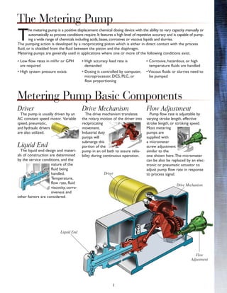
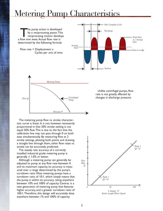
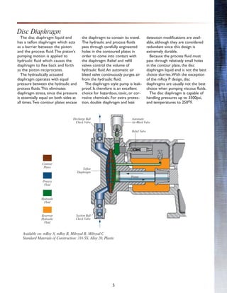
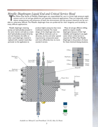
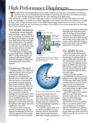
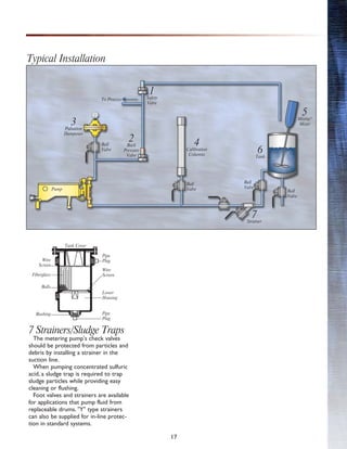
SlideShare a Scribd company logo
1 of 22
Download to read offline
Metering Pump Technology
Bulletin 210
The Metering Pump . . . . . . . . . . . . . . . . . . . . . . . .1
Metering Pump Basic Components . . . . . . . . . . . . .1
Metering Pump Characteristics . . . . . . . . . . . . . . . .2
Capacity and Pressure Capabilities Chart . . . . . . . .3
Liquid End Designs . . . . . . . . . . . . . . . . . . . . . . . . .4
Packed Plunger . . . . . . . . . . . . . . . . . . . . . . . . .4
Dics Diaphragm . . . . . . . . . . . . . . . . . . . . . . . . .5
Mechanically Actuated Diaphragm . . . . . . . . . . .6
Metallic Diaphragm and Critical Service Head . . .7
High Performance Diaphragm -
Advanced Liquid End Design . . . . . . . . . . . . . . . . . .8
Metering Pump Drive Mechanisms . . . . . . . . . . . .10
Hydraulic Bypass . . . . . . . . . . . . . . . . . . . . . . .10
Polar Crank . . . . . . . . . . . . . . . . . . . . . . . . . . .11
CENTRAC . . . . . . . . . . . . . . . . . . . . . . . . . . . . . .12
Capacity Adjustment . . . . . . . . . . . . . . . . . . . . . . .14
Modifications . . . . . . . . . . . . . . . . . . . . . . . . . . . .15
Metering Pump System Components . . . . . . . . . .16
Other Milton Roy Products . . . . . . . . . . . . . . . . .18
1
T
he metering pump is a positive displacement chemical dosing device with the ability to vary capacity manually or
automatically as process conditions require. It features a high level of repetitive accuracy and is capable of pump-
ing a wide range of chemicals including acids, bases, corrosives or viscous liquids and slurries.
The pumping action is developed by a reciprocating piston which is either in direct contact with the process
fluid, or is shielded from the fluid between the piston and the diaphragm.
Metering pumps are generally used in applications where one or more of the following conditions exist.
• Low flow rates in ml/hr or GPH
are required
• High system pressure exists
• High accuracy feed rate is
demanded
• Dosing is controlled by computer,
microprocessor, DCS, PLC, or
flow proportioning
• Corrosive, hazardous, or high
temperature fluids are handled
• Viscous fluids or slurries need to
be pumped
Driver
The pump is usually driven by an
AC constant speed motor. Variable
speed, pneumatic,
and hydraulic drivers
are also utilized.
Liquid End
The liquid end design and materi-
als of construction are determined
by the service conditions, and the
nature of the
fluid being
handled.
Temperature,
flow rate, fluid
viscosity, corro-
siveness and
other factors are considered.
Drive Mechanism
The drive mechanism translates
the rotary motion of the driver into
reciprocating
movement.
Industrial duty
pumps will
submerge this
portion of the
pump in an oil bath to assure relia-
bility during continuous operation.
Flow Adjustment
Pump flow rate is adjustable by
varying stroke length, effective
stroke length, or stroking speed.
Most metering
pumps are
supplied with
a micrometer
screw adjustment
similar to the
one shown here.The micrometer
can be also be replaced by an elec-
tronic or pneumatic actuator to
adjust pump flow rate in response
to process signal.
Liquid End
Driver
Drive Mechanism
Flow
Adjustment
Metering Pump Basic Components
The Metering Pump
2
T
he pump action is developed
by a reciprocating piston.This
reciprocating motion develops
a flow sine wave.Actual flow rate is
determined by the following formula:
Flow rate = Displacement x
Cycles per unit of time.
Unlike centrifugal pumps, flow
rate is not greatly affected by
changes in discharge pressure.
The metering pump flow vs. stroke character-
istic curve is linear. It is not, however, necessarily
proportional in that 50% stroke setting is not
equal 50% flow.This is due to the fact that the
calibration line may not pass through 0 on both
axes simultaneously. By measuring flow at 2
stroke settings, plotting both points and drawing
a straight line through them, other flow rates vs.
stroke can be accurately predicted.
The steady rate accuracy of a correctly
installed industrial grade metering pump is
generally + 1.0% or better.
Although a metering pump can generally be
adjusted to pump at any flow rate between 0
and its maximum capacity, its accuracy is meas-
ured over a range determined by the pump's
turndown ratio. Most metering pumps have a
turndown ratio of 10:1, which simply means that
the pump is within its accuracy rating anywhere
between 10% and 100% of capacity. Centrac is a
new generation of metering pump that features
higher accuracy, and a greater turndown ratio of
100:1.Therefore, this design will accurately dose
anywhere between 1% and 100% of capacity.
Metering Pump Characteristics
Average
Flow
Suction
Time
Peak Flow-
π x Average
Flow
One Complete Cycle
Discharge
Metering Pump
Centrifugal
Pump
Flow Q
Pressure P
Flow
Rate
Q
0 50 100
Point 2
Q2. S2
Point 1
Q1. S1
% Setting “S”
Stroke Length Driver Speed
3
The maximum capacity of each
pump is determined by gear ratio,
piston diameter, and motor RPM.
Maximum pressure rating applies
to smaller piston diameters in each
model.As the piston diameter and
stroking speed increase, pressure
capacity decreases. See specific
product data sheet for actual pres-
sure rating at desired flow rate.
Capacities shown are for simplex
pumps. For those pumps that can
be supplied with more than one
head, multiply the capacity by the
number of heads to determine
total capacity.
Capacity and Pressure Capabilities
Capacity Per Head–GPH
0
5
10
20
30
40
50
75
100
150
200
350
500
750
1000
1500
2000
3000
24”
mRoy XT & XW
Maximum Pressure
1800-3000 psi
Maximum No. Heads
2
23”
mRoy XT
Maximum–
1.6 GPH (6 LH)
Minimum–
0.4 GPH (1.5 LH)
mRoyA & B
Maximum Pressure
350-1500 psi
Maximum No. Heads
2
mRoy A
Maximum–
30 GPH (114 LH)
Minimum–
0.065 GPH (.246 LH)
8”
13”-24”
maxRoy B
Maximum Pressure
150 psi
Maximum No. Heads
1
maxRoy B
Maximum–
227 GPH (859 LH)
Minimum–
13.5 GPH (51.1 LH )
Milroyal B
Maximum Pressure
7500 psi
Maximum No. Heads
8
Milroyal B
Maximum–
500 GPH (1893 LH)
Minimum–
0.11 GPH (42 LH)
Centrac B
Maximum Pressure
1575 psi
Maximum No. Heads
2
Centrac B
Maximum–
550 GPH (2082 LH)
Minimum–
0.45 GPH (100:1 Turndown)
121
/4”-271
/2”
Centrac S
Maximum Pressure
9000 psi
Maximum No. Heads
2
Centrac S
Maximum–
39.7 GPH (150 LH)
Minimum–
4.0 GPH (15 LH)
11”
18”
Milroyal C
Maximum Pressure
7500 psi
Maximum No. Heads
5
Milroyal C
Maximum–
2510 GPH (9500 LH)
Minimum–
0.43 GPH (1.628 LH)
PrimeRoyal
Maximum Pressure
30,000 psi
Maximum No. Heads
3
PrimeRoyal
Maximum–
2510 GPH (9500 LH)
Minimum–
0.43 GPH (1.628 LH)
72”
mRoy B
Maximum–
85 GPH (322 LH)
Minimum–
0.475 GPH (1.79 LH)
mRoy XW
Maximum–
6.7 GPH (25 LH)
Minimum–
2.8 GPH (9.8 LH)
27”
MacRoy
Maximum Pressure
175 psi
Maximum No. Heads
1
MacRoy
Maximum–
300 GPH (1135 LH)
Minimum–
0.018 GPH (0.068 LH)
mRoyXT
mRoyXWMilroyal D
Maximum Pressure
3000 psi
Maximum No. Heads
6
Milroyal D
Maximum–
53 GPH (200 LH)
Minimum–
0.0081 GPH (0.0307 LH)
25”
4
T
he liquid end, which is the
wetted part of the pump, is
selected to meet the specif-
ic service conditions of the applica-
tion. Required flow and pressure
ratings are considered, as well as
the physical and chemical proper-
ties of the liquid.The liquid end's
ability to protect the environment
is also a major consideration
when dealing with toxic or haz-
ardous materials.
All liquid ends have several fea-
tures in common. First, the liquid
is drawn into the wetted end by
the rearward motion of a piston,
and expelled by the forward
motion.To achieve this, the meter-
ing pump is supplied with check
valves at the suction and discharge
connection points.
During the suction portion of the
stroke, the motion of the piston lifts
the suction ball check from its seat
allowing liquid into the pump.At the
same time, the piston's motion and
system back pressure holds the
upper check valve (discharge) closed.
This is then reversed during the dis-
charge stroke.
Check valves are available in sever-
al different designs and configura-
tions.The choice of ball or poppet
style is determined by Milton Roy's
Engineering department based on
capacity of the specific pump.
Most pumps feature either single or double ball configuration as standard. The
user can also select single or double ball when the application is better served by
one or the other. For example, slurries or liquids with large fibers or particles can
cause a single ball to leak if particles are trapped between the ball and seat.
Therefore, a double ball check offers more stability and accuracy. On the other
hand, since each check valve causes some resistance in the flow path even when
open, viscous fluids are better handled with a single ball suction check valve.
Single
Ball
Check
Valve
Double
Ball
Check
Valve
Poppet
Style
Check
Valve
Packed Plunger
The packed plunger style liquid end is the only
liquid end in which the piston is in direct contact
with the process fluid.This direct contact offers
a number of advantages, including: high suction
and discharge pressure capabilities; high temper-
ature resistance, and lowest NPSH requirements.
The reciprocating piston requires packing to
seal the wetted parts from the atmosphere.This
simple design is effective, but places limitations
on the use of packed plunge pumps in certain
applications.
Because a small amount of controlled leakage
past the packing must be expected, this style
liquid end should not be used with hazardous or
toxic chemicals.Additionally, the friction between
the piston and the packing results in wear that
increases leakage. Periodic packing adjustment is
necessary to maintain volumetric efficiency.To
avoid problems associated with leakage, consider
a diaphragm style liquid end.
The packed plunger can handle pressures up
to 15,000 psi, and temperatures to 600oF (with
special modifications).
Available on: Milroyal B, Milroyal C, Milroyal D, Centrac, and
Maxroyal Standard Materials of Construction: 316 SS, Alloy 20,
Cast Steel (larger models)
Liquid End Designs
Discharge
Suction
Piston
Discharge Ball
Check Valve
Process
Fluid
Process
Fluid
Ball
Check
Seat
Suction Ball
Check Valve
Discharge Ball
Check Valve
Grease Fitting
Packing Lantern Ring
Suction Ball
Check Valve
Piston
5
Available on: mRoy A, mRoy B, Milroyal B, Milroyal C
Standard Materials of Construction: 316 SS, Alloy 20, Plastic
Process
Fluid
Hydraulic
Fluid
Reservoir
Hydraulic
Fluid
Discharge Ball
Check Valve
Relief Valve
Piston
Automatic
Air-Bleed Valve
Teflon
Diaphragm
Suction Ball
Check Valve
Contour
Plates
The disc diaphragm liquid end
has a teflon diaphragm which acts
as a barrier between the piston
and the process fluid.The piston's
pumping motion is applied to
hydraulic fluid which causes the
diaphragm to flex back and forth
as the piston reciprocates.
The hydraulically actuated
diaphragm operates with equal
pressure between the hydraulic and
process fluids.This eliminates
diaphragm stress, since the pressure
is essentially equal on both sides at
all times.Two contour plates encase
the diaphragm to contain its travel.
The hydraulic and process fluids
pass through carefully engineered
holes in the contoured plates in
order to come into contact with
the diaphragm. Relief and refill
valves control the volume of
hydraulic fluid.An automatic air
bleed valve continuously purges air
from the hydraulic fluid.
The diaphragm style pump is leak-
proof. It therefore is an excellent
choice for hazardous, toxic, or cor-
rosive chemicals. For extra protec-
tion, double diaphragm and leak
detection modifications are avail-
able, although they are considered
redundant since this design is
extremely durable.
Because the process fluid must
pass through relatively small holes
in the contour plate, the disc
diaphragm liquid end is not the best
choice slurries.With the exception
of the mRoy P design, disc
diaphragms are usually not the best
choice when pumping viscous fluids.
The disc diaphragm is capable of
handling pressures up to 3500psi,
and temperatures to 250oF.
Disc Diaphragm
Mechanically-actuated pumps
operate with a plunger directly
attached to the diaphragm.This
attachment generally takes place
from a bolt and clamp being
placed through the plunger and
through the diaphragm.The direct
attachment of the piston to the
diaphragm connects the pump's
drive and motor to the liquid end.
The motion of the pump drive
moves the plunger back and forth,
thereby causing suction from the
supply tank and pumping the fluid
of choice through the attached
conveyance infrastructure.This
series of pumps generally find
pressure peaks at 200 PSI, but are
only limited to flow as a matter of
wetted end volume. Maximum life
of the pump can be achieved by
replacing the diaphragm at the
recommended service interval.
Leak detection can be easily found
from the air-filled chamber resid-
ing generally at atmospheric pres-
sure on the drive side of the liq-
uid end.This provides the least
expensive leak detection option in
the marketplace.
As with any chemical where gas
binding can be a problem, it is
recommended that a degassing
valve be used to release off-gases
from the agitation or pressure
changes experienced by a liquid
having off-gas characteristics.
Some of these liquids that can
generate off-gases as a result of
pressure losses are NaOCl,
H2O2, and some specialty chemi-
cals. Mechanically-actuated pumps
work well in these applications
providing 10:1 turndown as a
standard across the product line.
The addition of VFD technology
will bring the turndown as high
as 100:1.
Mechanically-diaphragm pumps
are easily maintained and provides
years of service for little effort.
6
Liquid End Designs
T
he Milton Roy MacRoy Family of mechanically-actuated diaphragm pump represents the best balance
between low pump cost and high quality performance. Because it has zero diaphragm leakage, it makes a
great pump for critical and otherwise expensive chemicals or where environmental issues are involved.
The mechanically-actuated series is an excellent choice where slurries and abrasive chemicals are required up to
the pump's maximum flow and pressure ranges.They are also well tolerant of high viscosity liquids providing an
economical solution for a variety of difficult applications.
Mechanically Actuated Diaphragm Design
Hydraulic
Fluid
Available on: MacRoy, Standard Materials of Construction: 316 SS, Alloy 20, Plastic
Process
Fluid
Set Screw
Check Valve
Assembly
Check Valve
Assembly
Diaphragm
Head
Diaphragm Cap
Oil Seal
Slotted Pan
Head Screw
Diaphragm
Assembly
Diaphragm
Assembly
7
T
he Milton Roy Series of Metallic Diaphragms are unparalleled for use in critical, high pressure appli-
cations such as oil and gas platforms and specialty industrial applications.They are especially useful
where temperatures and pressures of both the environment and the process chemical can be vari-
able or otherwise difficult.The Metallic diaphragm lines are preferred for their longevity and durability in
many difficult applications.
Metallic Diaphragm Liquid End and Critical Service Head
Available on: Milroyal C and PrimeRoyal: 316 SS, Alloy 20, Plastic
Metallic diaphragm metering
pumps are hydraulically-actuated in
the same manner and style as a stan-
dard hydraulically-actuated drive liq-
uid end. However, the teflon or
other usual diaphragm material is
replaced with a special metal alloy
particular to the application to
produce higher pressures than more
traditional materials.The metal
design of the diaphragm also man-
ages difficult chemicals such as
abrasives, slurries and other special
requirements compounds easier
and more efficiently than its more
standard version.
Many oil and gas offshore drilling
platforms require metallic
diaphragms because of their high
reliability and longevity. In any appli-
cation where critical service is
required, the Milton Roy Metallic
Diaphragm is the product of choice
for these chemical dosing situations.
Diaphragm
Head
Suction Ball
Check Valve
Diaphragm
Head Bolts /Nuts
Displacement
Chamber
Set Screws
Plunger
Adapter
Nut
Plunger Sleeve
Plunger
Detail B
Diaphragm
O-Ring
O-Ring
O-Ring Backup
O-Ring
Backup
O-Ring
Screws
Hydraulic
Fluid
Process
Fluid
8
T
he High Performance Diaphragm liquid end, HPD, combines all of the best characteristics of traditional
liquid ends into one technologically advance design. It’s operating characteristics and simplicity of opera-
tion make the best pump to consider first for most metering pump applications.
HPD operations is similar to the disc diaphragm in that it is hydraulically actuated and utilizes the same
shape and diaphragm. It is similar to a tubular diaphragm in the respect that the process fluid has a “straight
through” path through the liquid end. It is low NPSH requirements requirements are similar to that of a
packed plunger liquid end. But the primary advantages of the HPD are the unique design features that sepa-
rate it from traditional designs.
The MARS Advantage
A hydraulically actuated diaphragm
liquid end design requires a refill sys-
tem to compensate for hydraulic fluid
that bleeds past the piston or through
an air bleed valve during normal oper-
ation. Hydraulic fluid is also expelled
from the chamber through the inter-
nal relief valve when the system expe-
riences excess pressure, and there-
fore must also be replenished.
The HPD features a Mechanically
Actuated Refill System (MARS) that
offers a number of advantages over
traditional refill systems.To under-
stand the advantages of MARS, tradi-
tional refill systems must first be
explored.
Traditional Designs
Traditional designs use a system that
refills the chamber when a vacuum is
created by the inability of the
diaphragm to move beyond the
hydraulic contour plate. It also refills
when the suction is momentarily or
permanently starved by accidental
valve closure, insufficient NPSH, or
other similar occurrences.When this
happens, the hydraulic fluid chamber
is overfilled because a vacuum has
been created even though the
diaphragm has not been able to travel
rearward.To avoid diaphragm rupture
due to overfilled hydraulic oil, a
process side contour plate stops the
diaphragm's forward travel, and forces
the hydraulic relief valve to open, thus
expelling the excess fluid.
The contour plate is a concave
(actually, concave-convex) disc that
supports the diaphragm and limits its
travel.The plate has a series of holes
bored through it to permit the fluid
to come into contact with the
diaphragm.The pattern and size of
these holes requires careful engineer-
ing to maintain the contour plate
strength required to withstand the
force of the diaphragm experience at
the operating pressure.
The hydraulic contour plate does
not cause any problems in pump
operation since the hydraulic fluid
passes easily through the contour
plate holes. However, a process con-
tour plate, required by traditional disc
diaphragm liquid ends, places limita-
tions on the types of process fluids
the pump can handle (such as slur-
ries) since the process fluid must also
pass through contour plate holes.The
process contour plate also creates a
pressure loss which raises the NPSH
requirement of the liquid end.
The MARS System
The MARS System eliminates the
need for a process contour plate by
assuring that the hydraulic fluid can
only be refilled when the diaphragm
has traveled all the way back to the
contour plate.The diaphragm presses
against the MARS valve, which only
then permits a poppet valve to open
from the vacuum created by insuffi-
cient hydraulic fluid. (See the illustra-
tion lower right)
Hydraulic overfill is therefore
impossible.With the process contour
plate gone, the straight through path
of the process liquid makes the HPD
a perfect choice for slurries and vis-
cous materials. It also lowers the
NPSH requirements of the pump,
since pressure loss through a process
contour plate is eliminated.
The MARS system also simplifies
HPD start-up. Unlike other
hydraulic liquid ends, the refill valve
does not need adjustment.
Additionally, since the HPD
hydraulic fluid cannot be overfilled,
there is no need to perform deli-
cate procedures to synchronize
hydraulic fluid balances (a difficult
task required for tubular and other
double diaphragm liquid ends).With
HPD, you just fill the reservoirs, and
turn it on.
Traditional Liquid End with Process
and Hydraulic contour Plates (refill
system not shown)
Typical Contour Plate(Section cutaway)
High Performance Diaphragm...
Discharge
Suction
Process Contour Plate
Process
Fluid
Hydraulic Side
Contour Plate
Hydraulic Fluid
Piston
Diaphragm
9
T
he HPD features a pre-
shaped PTFE/elastomer
composite disc diaphragm.
On the process side, the chemical
resistance of PTFE is utilized. On
the hydraulic side, the elastomer
imparts favorable elastic and
mechanical factors.
The composite diaphragm elimi-
nates the inherent problems of
pure PTFE diaphragms. PTFE tends
to cold flow when compressed
between two metal parts (such as
those required to seal the
hydraulic side from the process
side).The HPD composite
diaphragm features an integral "O"
ring seal around the perimeter of
the diaphragm, which provides a
better seal between hydraulic and
process fluids than conventional
diaphragm materials.
The HPD is capable of handling
pressures up to 3025 psi and tem-
peratures up to 300oF (with spe-
cial modifications).
Available on: Milroyal C., Milroyal D, Centrac and Maxroyal.
Standard Materials of Construction: 316SS. Alloy 20, Plastic.
HPD Pre-shaped Composite Diaphragm
MARS System Operation
Pre-shapes
Composite
Diaphragm.
Figure 1
Diaphragm (A) and piston (C) are
full forward. Mars valve (B) in for-
ward position holds poppet valve (D)
closed, preventing refill line hydraulic
oil from entering the chamber.
Figure 2
Diaphragm (A) and piston (C) are full
rearward. Mars valve (B) is also rear-
ward due to diaphragm position, thus
freeing poppet (D) to open if required.
Poppet (D) is shown closed, indication
hydraulic oil refill is not required.
Figure 3
Diaphragm (A) and piston (C) are full
rearward, once again forcing Mars valve
(B) to its rearward position, which allows
poppet (D) to open if required. Low oil
volume creates a vacuum and opens pop-
pet, permitting hydraulic fluid to enter the
chamber from the refill line.
...Advanced Liquid End Technology
Full side view of HPD Liquid
End on MilRoyal Drive
Air Bleed/Relief Valve
Piston
Hydraulic Refill Line
Removable
Check Valve
Composite
Diaphragm
Mechanically Actuated
Refill System (MARS)
MARS Valve
Poppet
Process
Fluid
Hydraulic
Fluid
Reservoir Hydraulic
Fluid
A
B
C
D
A C
D D
A C
PTFE Elastomer
B B
Standard Materials:
316SS. Alloy 20, Plastic.
Milroyal B
HPD Low Flow
All Milton Roy drive mechanisms feature gears that are submerged in an oil bath to assure long life. Capacity
can be adjusted while the pump is running or stopped, + 1.0% accuracy over a 10:1 turn-down ratio.
Hydraulic By-Pass
The hydraulic by-pass mechanism features a piston with a constant stroke length that pumps hydraulic fluid,
thus transferring the pumping motion to a diaphragm.Therefore, this type of drive can only mate with a hydrauli-
cally actuated diaphragm liquid end.
Capacity is varied by changing the location of a hydraulic by-pass port over the piston's path of travel. If the
port is positioned at 50% of the piston's stroke length, hydraulic fluid will be relieved through the port during the
first half of the piston's stroke, and pumped against the diaphragm during the remaining half.This type of drive is
often called "hydraulic lost motion," because a portion of the piston's travel does not transmit pumping energy
when the capacity adjustment is less than 100%. Both the mRoy and the Maxroy are hydraulic by-pass style
pumps. Both develop reciprocating piston motion by way of a worm gear and eccentric.
maxRoy B
In the maxRoy, capacity is varied by positioning a stroke adjust sleeve over by-pass ports bored through the hol-
lowed piston.When operating at 100%, the ports are covered, which traps hydraulic fluid in the hydraulic pumping
chamber. Once trapped, the piston's pumping action forces the hydraulic fluid to flex the diagram.
A cup valve, which is attached to the diaphragm, closes all hydraulic paths to the diaphragm when it comes to the
diaphragm when it has reached the full forward position.This eliminates a process contour plate, as well as excessive
hydraulic pressure on the diaphragm, since any excess hydraulic fluid in the hydraulic pumping chamber cannot reach
the diaphragm, and is forced through the
internal relief valve to the fluid reservoir.
The maxRoy drive features:
• Maximum flow rates between 135 GPH
and 227 GPH
• Maximum discharge pressures of 150 psi
The maxRoy is an excellent choice for
mid-range metering pump capacity at low
pressure. Its design is more economical than
high pressure pumps in the same capacity
range, without sacrificing ruggedness and
accuracy.The "straight through" process fluid
path allows maxRoy to be applied to many of
the same services as the HPD liquid end.
mRoy A, mRoy B
In the mRoy, the piston pumps
hydraulic fluid, which either forces the
diaphragm to flex, or is relieved
through the by-pass port.A control
valve positions the port based on a
desired capacity setting.
The mRoy drive with its standard
disc diaphragm liquid end features:
• Simplex or Duplex liquid ends
• Maximum capacities ranging
between 0.43 GPH and 85 GPH
(170 GPH Duplex)
• Maximum pressures up to 1800 psi
The mRoy drive with
it’s standard disc
diaphragm liquid end.
Eccentric
Metering Pump Drive Mechanisms
Hydraulic
Fluid
Reservoir Hydraulic
Fluid
Worm
Gear Set
PistonHydraulic Oil
in Pumping ChamberSuction
Discharge
Eccentric
Stroke Adjust
Sleeve
Cup Valve
Diaphragm
Capacity Adjustment
By-Pass
Ports
Worm Gear Set
Stroke
Length
Suction
DischargeControl
Valve
Motor
By-Pass Control
Plunger
By-Pass Port
Diaphragm
Hydraulic
Fluid
Reservoir Hydraulic
Fluid
Process
Fluid
10
11
To achieve a high thrust capacity
and extend component life, the
Milroyal B and C polar crank drives
feature a pressurized lubrication sys-
tem.This positive oil pressure lubrica-
tion ensures long bearing life and per-
mits the Milroyal pump to operate at
very high suction and discharge pres-
sures.
As the
crosshead
moves forward
during the dis-
charge stroke,
oil from the
reservoir is
drawn up
through a bail
check into a
cavity in the crosshead. During the
suction (rearward) stroke the lubri-
cant is trapped. It is then forced
through the crosshead, into the
crosshead connecting rod bearing,
through the hollow connecting rod,
and finally to the crank connecting
rod bearing. By forcing the oil through
this path, every moving part is lubri-
cated during ever complete cycle of
the pump.
To reduce the wear of moving parts
and extend oil life, a magnetic strainer
cleans the oil before it enters the
pressurized system.
T
he unique polar crank drive
is the heart of the Milroyal
series metering pump. It is
considered the most advanced and
reliable variable stroke length drive
available in high pressure/high flow
industrial duty metering pumps.
In the polar crank drive, a high
speed worm gear reduces the RPM
supplied by the motor, and provides
the lower RPM to a rotating crank. A
connecting rod with spherical bear-
ings on each end links the crank to
the crosshead and piston assembly.
The worm gear and crank assembly
pivots in an arc about the worm shaft
center to change stroke length.The
piston stroke length is determined by
the angle of the assembly.
For example, when the pump is at
zero stroke, the worm/crank assem-
bly is in a vertical position. (Figure 1)
The crank then rotates in a vertical
plane and one end of the connecting
rod revolves with it.The crosshead
and the piston remain stationary
because no reciprocating action is
produced.When the pump is adjust-
ed full stroke (or maximum capacity),
the rotating crank is moved to its
maximum angle from the vertical
axis. (Figure 2) At the top of the rota-
tion cycle the connecting rod is
pushed forward, moving the
crosshead and piston to the full for-
ward position at the end of the dis-
charge stroke. As the crank continues
to rotate, the angle of the crank
causes the connecting rod to pull
the crosshead and piston until it
reaches the full rearward position
at which point the connecting rod
has reached the bottom of the
rotation cycle.
Regardless of the stroke length
setting, the top of the rotation
cycle always forces the crosshead
and the piston to the full forward
position at the end of each dis-
charge stroke.This assures com-
plete scavenging of the liquid end
during each stroke cycle.
The angle of the polar crank can
be adjusted in infinite increments
between zero and maximum stroke
for extremely accurate controlled
volume pump settings.
Polar Crank
Lubricating Oil
Relief Valve
Lubricating Oil
High Speed
Worm
Worm Gear
Connecting RodMagnetic Strainer
Crosshead
Piston
Micrometer
Stroke
Adjustment
This illustration demonstrating the
polar crank at full and zero strokes
High Speed
Worm
Micrometer
Capacity
Control
Worm Gear
Rotating Crank
Lubricating Oil
Lubricating Oil
Relief Valve
Figure 1
Zero Stroke
Connecting
Rod
Cross
Head
High Speed Worm
Worm
GearRotating
Crank
Suction
Discharge
Stroke
Length
Figure 2
Full Stroke
The Milroyal polar crank drive features:
• Maximum capacity ranges
between 0.033 GPH (125mL/hr.)
and 2510 GPH depending on
frame size, stroking speed, and
plunger diameter
• Discharge pressures up to
7500 psi
• Up to 8 pumps multiplexed
and driven by one motor
• HPD, packed plunger, disc
diaphragm, or tubular
diaphragm liquid ends
Pressurized Lubrication System
Centrac's impressive operating
characteristics are the result of a
unique constant stroke length drive
mechanism that depends on a spe-
cial electronic variable speed drive
to vary pump flow rate.This offers
a number of advantages.
Traditional designs utilize worm
gear sets to convert motor rotation
to reciprocating motion through an
eccentric or similar mechanism.
Worm gears are the best choice
when the drive mechanism is
required to
incorpo-
rate a vari-
able stroke
length
adjustment.
They oper-
ate well at
high rotary
speeds, due
to an oil
shield that
develops
between
the gear surfaces. Unfortunately, they
lose that shield at lower speeds,
which causes wear and raises motor
torque requirements.This limits
worm gears to a 10:1 turndown
ratio.
Centrac, on the other hand, uti-
lizes a special helical gear set. Since
there is no need for stroke length
adjustment, the gear set is very
simple.Also, helical gears are known
for operating with low noise and
low friction. Combined with a basic
scotch yoke mechanism to develop
reciprocating motion, this gear set
runs quietly and efficiently with few
moving parts.All moving parts are
submerged in oil to ensure long life.
The graph below indicates the
greatest advantage of Centrac's spe-
cial gear design.The flat torque curve
(vs. the worm gear set) allows
Centrac to operate at or below 1%
of speed without placing extra
demand on the motor, thus permit-
ting Centrac's 100:1 turndown ratio.
The simple drive mechanism also
allows Centrac to be
easily duplexed within
the same housing by
adding a second pis-
ton and liquid end
opposite the primary
liquid end. Centrac's
capacity can therefore
be doubled economi-
cally and efficiently.
Centrac's Advanced
Electronic Variable
Speed Drive
Conventional AC and DC variable
speed drives are limited to turn-
down ratios between 5:1 and 30:1.
This is insufficient to take advantage
of the turndown capabilities of
Centrac's gear design.
New technology in brushless DC
motors and controllers has created
advanced drives capable of strong
operation at low speeds. Centrac's
variable speed
drive delivers
rated torque
at less than
1% (100:1
turndown) of
maximum
rated RPM
while main-
taining steady
state speed
control at
better than +
0.1%. It is the
perfect match
for Centrac's
drive mecha-
nism.
12
C
entrac represents a new
concept in metering pump
drive design. It is the first
true innovation in metering pump
drives to be introduced in decades.
Centrac was developed by combin-
ing the highest level of gear reduction
design, and the latest technology in
electronic variable speed drives.The
result is a metering pump that boasts
twice the accuracy over a turndown
ratio ten times greater than tradition-
al designs.
Centrac's name clearly announces
its capabilities:
CENT-100:1 turndown ratio
R-Response & Reliability
AC - + 0.5% steady state accuracy
Centrac is different from tradition-
al designs in many ways.The most
significant way is the close relation-
ship between the driver and drive
mechanism and how they enhance
overall pump performance.To
understand Centrac better, these
two design elements and their inter-
dependence need to be explored.
Advanced Drive Technology
CENTRAC – The Automatic Process
CENTRAC Scotch
Yoke Drive
Torque vs. Motor Speed-CENTRAC and Worm Gears
Motor Speed-RPM
200
180
160
140
120
Block transfers Rotating Eccentric
Motion to Reciprocating Motion
Full
Load
0 10 20 50 100 175 200
Low Speed
Eccentric & Gear
Motor Drive Gear
(18 to 1800 RPM)
10:1 Turndown
T
ypical of Worm Gear Pump Drives
100%
1400 1500
100:1 Turndown
Operator Control Station
Centrac's Unique Gear Reduction System
13
Centrac's variable speed drive
features:
• 100:1 turndown ratio
• + 0.1% steady state speed
control
• smart commutation - permits
accurate feedback signal
• no brushes (low maintenance)
• constant torque at low speeds -
permits efficient driver sizing
100:1 Turndown Ratio
The flexibility of a 100:1 turn-
down ratio permits Centrac to be
applied where a wide range of
dosage rates are required. It also
provides built-in growth potential
by pumping efficiently in systems
requiring a fraction of the pump's
capacity for the short term during
start-up or early phases of an
expanding project. Centrac provides
all this without compromising accu-
racy or drive power.
Response
Centrac responds instantly to
changes in dosage rate. Its constant
stroke length does not upset bal-
ance within the liquid end hydraulic
system, that is, hydraulic fluid vol-
ume remains constant.When the
hydraulic balance is disturbed, as in
variable stroke length designs, the
full result of dosage changes can
take minutes or hours.
Centrac's instant response provides
smoother operation in closed loop or
automated systems. It also assures
proper dosage at all time in systems
requiring very close dosage tolerance.
Accuracy
Centrac's + 0.5%
steady state accura-
cy over its full
turndown ration is
a result of the
constant stroke
length, and the pre-
cise speed control
of Centrac's drive.
This level of accura-
cy provides maxi-
mum chemical econ-
omy while assuring
stable automatic
operation and opti-
mum process quality.
Centrac's features include:
• 100:1 turndown ratio
• + 0.5% steady state accuracy
• Instant response to dosage
changes
• Simple but robust design for
reliability
• Precise feedback signal
• Efficient drive sizing
• Mates with advanced HPD liquid
end for maximum performance
• Capacity range between 0.45
GPH minimum and 1100 GPH
maximum
Metering Pump
Liquid
End
Mounting
Surface
Main Gear
Driver Shaft
Gear Assembly
Optional Duplex
Configuration
Motor Mount
EccentricEccentric CageCrosshead
Connection Diagram
Drive Motor
Motor Control
Optional Remote
Operator Control
AC Input Power Remote Speed (Flow Rate)
Control Signal
Speed
(Flow Rate)
Output
Signal
14
M
etering pumps allow the user to vary capacity as the process requires.All Milton Roy metering pumps
permit adjustment whether the pump is running or not.
With the exception of the Centrac (see Centrac drive), Milton Roy pumps are supplied with a manual
micrometer for performing manual capacity adjustments. Depending on the type of drive mechanism and the
application requirements, one of several capacity adjustment options can be supplied.
Capacity Adjustment
Manual Micrometer
The manual micrometer can be
used to adjust the metering pump's
capacity anywhere between 0 and
100%.While not directly propor-
tional to flow, this calibrated adjust-
ment can be used to accurately set
pump capacity based on the pump
performance curve within + 1.0%
over the turndown ratio.
Electronic Actuator
Option Available for: mRoy A & B, MaxRoy, Milroyal B & C
The Milton Roy Electronic Actuator responds to electronic process signals or remote manual adjust-
ments. In addition, a local handwheel is provided to permit manual adjustments when unpowered.
Milton Roy's electronic actuator is different from electric actuators in that it utilizes electronic
limits. It is built around stepper motor technology, which allows it to travel precisely to position
without overshoot or hunting.
This design also provides superior operating characteristics such as:
• 100% duty cycle
• + 0.5% position accuracy or better
• low maintenance
Remote control stations are available for local/remote selection and manual capacity adjustment.
Specifications:
• NEMA 4 (Explosion proof
available)
• 4-20 mA input signal
standard
• Direct or reverse acting
Pneumatic Actuators
Option Available for: mRoy A & B, Milroyal B & C
Automatic systems that supply a pneumatic process signal benefit from the Milton Roy
pneumatic actuator.A separate air control panel is available for remote control and
auto/manual switching.
Specifications:
• 3-15 or 3-27 psi pneumatic signal
• Direct or reverse acting
• Requires 60 psi supply air pressure
Manual
Micrometer
• 1-5 VDC stroke position
output signal
• Single phase 50/60
cycle 115 VAC
Electronic Actuator on mRoy A
Pneumatic Actuator
15
Milton Roy's diaphragm liquid ends
are, by design, leakproof and durable.
In some applications, however, added
assurance is desired to protect the
pump from hostile chemicals, or pro-
tect the process from contamination
by hydraulic fluids. For these situa-
tions, Milton Roy has developed a
highly reliable diaphragm rupture
detection system.
The system consists of two sepa-
rate diaphragms, a hollow intermedi-
ate ring, and a pressure gauge or
switch. During the normal operation,
the two diaphragms are pushed tight-
ly together and are separated only
around their outside edge by the
intermediate ring.The rupture detec-
tion system senses a pressure only
when a diaphragm ruptures.The sys-
tem is not affected by changes in
pump discharge pressures.
This system is available for metallic
liquid end mRoys, maxRoys, and
HPD's. A different design centered
around sensing changes in conductiv-
ity is also available for a number of
liquid ends.
Modifications
Double Diaphragm With Diaphragm Rupture Detection System
Milton Roy offers a wide variety of standard pumps to satisfy most applications. In addition, our Applications
Engineering department is capable of supplying specialty engineered products.
Application Engineering: Custom Modifications
Capabilities include:
• Special liquid end materials
including diaphragms, diaphragm
heads, check valves, etc.
• Special piston diameters
• High temperature or pressure
modifications
• Unique multiplex arrangements
• Application counseling
• Special sensors, indications, or
instrument interface
• Special drive modifications or
gear ratios
16
Proper metering pump system operation depends upon the selection of appropriate system components.
Milton Roy offers high quality accessories to suit your application requirements.
Metering Pump System Components
4.CalibrationColumns
All Milton Roy metering pumps
are factory tested. Once installed,
pump calibration should be periodi-
cally determined to verify proper
operation, especially after the per-
formance of any maintenance.
Milton Roy calibration columns
provide an inexpensive means of
assuring pumping accuracy.
5.Mixroy®
Mixers
Accurate dosing requires proper
mixing of the solution being
pumped. Mixroy mixers are direct
drive, high speed units designed for
mixing medium and low viscosity
fluids and dispersion of light solids.
6.Tanks and Chemical
Feed Systems
Milton Roy offers tanks (up to
250 gallons capacity) in steel, stain-
less steel, and polyethylene.They
are also available with pumps
mounted, plumbed, and ready for
installation.
1.Safety Valves
Most piping systems require the
use of an external safety valve to
protect the piping from over-pres-
sure. Diaphragm pumps feature
internal safety valves to protect the
pump, but external safety valves are
still recommended. Milton Roy man-
ufactures safety valves for pressures
to 1500 psi and flow rates to 550
GPH. Standard safety valves are
available in steel, 316 SS, alloy 20,
and PVC.
2.Back Pressure Valves
To prevent unmetered liquid from
free-flowing through the pump,
metering pump systems require a
greater pressure in the discharge
line than the suction or inlet line.
When the process does not supply
minimum of 25 psi above the suc-
tion pressure, a back pressure valve
is required. Back pressure valves are
available for flow rates to 460 GPH
and pressures to 200 psi.
3.Pulsation Dampeners
The metering pump's reciprocat-
ing motion provides a pulsating dis-
charge flow.Applications requiring a
steady flow can eliminate over 90%
of the pulsations with a pulsation
dampener. Dampeners are available
for pressures to 1000 psi. Sizing is
based on cubic inch/stroke displace-
ment of the specific pump.
17
7 Strainers/Sludge Traps
The metering pump's check valves
should be protected from particles and
debris by installing a strainer in the
suction line.
When pumping concentrated sulfuric
acid, a sludge trap is required to trap
sludge particles while providing easy
cleaning or flushing.
Foot valves and strainers are available
for applications that pump fluid from
replaceable drums. "Y" type strainers
can also be supplied for in-line protec-
tion in standard systems.
Typical Installation
Pump
3
Pulsation
Dampener
2
Back
Pressure
Valve
1
Safety
Valve
To Process
4
Calibration
Columns
7
Strainer
6
Tank
5
Mixroy®
Mixer
Ball
Valve
Ball
Valve
Ball
Valve
Ball
Valve
Tank Cover
Pipe
PlugWire
Screen
Fiberglass
Balls
Wire
Screen
Lower
Housing
Bushing Pipe
Plug
18
Streaming Current Detector
Milton Roy's Streaming Current Detector
(SCD) is used to monitor and control
coagulants in water or wastewater treatment.
The SCD is an on-line instrument, therefore
consistent effluent quality is assured.
In addition to water and wastewater treat-
ment, the SCD is widely used in paper making,
petroleum, food, chemical, and other indus-
tries where close control of coagulant or
charge altering chemicals is beneficial.
Electronic Actuators
A broad line of electronic actuators, similar to those used on Milton Roy pumps, is available for control valve
actuation and other applications requiring precision and dependability.These advanced electronic actuators out-
perform standard electric designs by utilizing stepper motor technology.
Other Milton Roy Products
Milton Roy's electronic actuators offer the following advantages:
• 100% duty cycle
• Electronic limit switches
• Direct to position operation-no
hunting or overshoot
• Rotary or linear designs
• AC and DC units
• Responds to 4-30 mA, split range,
digital and other process signals
• Maximum torque - 3800 in-lbs
(317 ft-lbs)
• Maximum thrust - 1100 lbs
• Optional controllers and failsafe units
The Milton Roy Family of
Streaming Current Detectors
Catálogo Geral Milton Roy

More Related Content

What's hot

Maintenance of Pumps
Maintenance of PumpsMaintenance of Pumps
Maintenance of PumpsHammad Akber
 
Basic Unit Conversions for Turbomachinery Calculations
Basic Unit Conversions for Turbomachinery Calculations Basic Unit Conversions for Turbomachinery Calculations
Basic Unit Conversions for Turbomachinery Calculations Vijay Sarathy
 
Governing and protection system
Governing and protection systemGoverning and protection system
Governing and protection systemSachin Pyasi
 
CENTRIFUGAL PUMPS TRAINING.pdf
CENTRIFUGAL PUMPS TRAINING.pdfCENTRIFUGAL PUMPS TRAINING.pdf
CENTRIFUGAL PUMPS TRAINING.pdfyusuf699644
 
Control Valve Types
Control Valve TypesControl Valve Types
Control Valve TypesBrannon Gant
 
Basic Control Valve Sizing and Selection
Basic Control Valve Sizing and SelectionBasic Control Valve Sizing and Selection
Basic Control Valve Sizing and SelectionISA Boston Section
 
Centrifugal Pump Testing Standards - Presentation by ITT
Centrifugal Pump Testing Standards - Presentation by ITTCentrifugal Pump Testing Standards - Presentation by ITT
Centrifugal Pump Testing Standards - Presentation by ITTSahyog Shishodia
 
Pressure Relief Devices_Presenation
Pressure Relief Devices_PresenationPressure Relief Devices_Presenation
Pressure Relief Devices_Presenationsumit handa
 
Boiler Water Circulation Pumps
Boiler Water Circulation PumpsBoiler Water Circulation Pumps
Boiler Water Circulation PumpsGerard B. Hawkins
 
All You Need To Know About Cavitation In Centrifugal Pumps
All You Need To Know About Cavitation In Centrifugal PumpsAll You Need To Know About Cavitation In Centrifugal Pumps
All You Need To Know About Cavitation In Centrifugal PumpsRotech Pumps & Systems Inc.
 
Ease Control Valve Selection
Ease Control Valve SelectionEase Control Valve Selection
Ease Control Valve SelectionJozsef Magyari
 
psv and pvrvdesign calculation.ppt
psv and pvrvdesign calculation.pptpsv and pvrvdesign calculation.ppt
psv and pvrvdesign calculation.pptssuser73bb74
 
Pressure Relief valve sizing and design
Pressure Relief valve sizing and designPressure Relief valve sizing and design
Pressure Relief valve sizing and designHéctor Nguema Ondo
 
Overpressure protection
Overpressure protectionOverpressure protection
Overpressure protectionWei Chiao Kuo
 

What's hot (20)

Maintenance of Pumps
Maintenance of PumpsMaintenance of Pumps
Maintenance of Pumps
 
Basic Unit Conversions for Turbomachinery Calculations
Basic Unit Conversions for Turbomachinery Calculations Basic Unit Conversions for Turbomachinery Calculations
Basic Unit Conversions for Turbomachinery Calculations
 
Hydraulic course manual
Hydraulic course manualHydraulic course manual
Hydraulic course manual
 
Governing and protection system
Governing and protection systemGoverning and protection system
Governing and protection system
 
CENTRIFUGAL PUMPS TRAINING.pdf
CENTRIFUGAL PUMPS TRAINING.pdfCENTRIFUGAL PUMPS TRAINING.pdf
CENTRIFUGAL PUMPS TRAINING.pdf
 
Control Valve Types
Control Valve TypesControl Valve Types
Control Valve Types
 
Basic Control Valve Sizing and Selection
Basic Control Valve Sizing and SelectionBasic Control Valve Sizing and Selection
Basic Control Valve Sizing and Selection
 
Centrifugal Pump Testing Standards - Presentation by ITT
Centrifugal Pump Testing Standards - Presentation by ITTCentrifugal Pump Testing Standards - Presentation by ITT
Centrifugal Pump Testing Standards - Presentation by ITT
 
Pressure Relief Devices_Presenation
Pressure Relief Devices_PresenationPressure Relief Devices_Presenation
Pressure Relief Devices_Presenation
 
Boiler Water Circulation Pumps
Boiler Water Circulation PumpsBoiler Water Circulation Pumps
Boiler Water Circulation Pumps
 
Control Valves (THINKTANK®️)
Control Valves (THINKTANK®️)Control Valves (THINKTANK®️)
Control Valves (THINKTANK®️)
 
All You Need To Know About Cavitation In Centrifugal Pumps
All You Need To Know About Cavitation In Centrifugal PumpsAll You Need To Know About Cavitation In Centrifugal Pumps
All You Need To Know About Cavitation In Centrifugal Pumps
 
Hydraulic valves
Hydraulic valvesHydraulic valves
Hydraulic valves
 
Control valve
Control valveControl valve
Control valve
 
Ease Control Valve Selection
Ease Control Valve SelectionEase Control Valve Selection
Ease Control Valve Selection
 
Control valves
Control  valvesControl  valves
Control valves
 
psv and pvrvdesign calculation.ppt
psv and pvrvdesign calculation.pptpsv and pvrvdesign calculation.ppt
psv and pvrvdesign calculation.ppt
 
Pressure Relief valve sizing and design
Pressure Relief valve sizing and designPressure Relief valve sizing and design
Pressure Relief valve sizing and design
 
Overpressure protection
Overpressure protectionOverpressure protection
Overpressure protection
 
Industrial hydraulics
Industrial hydraulicsIndustrial hydraulics
Industrial hydraulics
 

Similar to Catálogo Geral Milton Roy

Catálogo Williams _ X series
Catálogo Williams _ X series Catálogo Williams _ X series
Catálogo Williams _ X series Vibropac
 
API Pumps design, application and selection
API Pumps design, application and selectionAPI Pumps design, application and selection
API Pumps design, application and selectionAlireza Bagherian
 
High pressure cleaner 70150
High pressure cleaner 70150High pressure cleaner 70150
High pressure cleaner 70150aman1312
 
High pressure water cleaner- Pressure Jet System
High pressure water cleaner- Pressure Jet SystemHigh pressure water cleaner- Pressure Jet System
High pressure water cleaner- Pressure Jet Systemaman1312
 
Improving Energy Efficiency of Pumps and Fans
Improving Energy Efficiency of Pumps and FansImproving Energy Efficiency of Pumps and Fans
Improving Energy Efficiency of Pumps and Fanseecfncci
 
Guide to-choosing-the-right-pump-for-hygienic-applications
Guide to-choosing-the-right-pump-for-hygienic-applicationsGuide to-choosing-the-right-pump-for-hygienic-applications
Guide to-choosing-the-right-pump-for-hygienic-applicationsChevronelle
 
High pressure jet cleaner 14 lpm 140 bar
High pressure jet cleaner 14 lpm 140 barHigh pressure jet cleaner 14 lpm 140 bar
High pressure jet cleaner 14 lpm 140 baradmin_PJSPL
 
High pressure jet cleaner 14 lpm 140 bar
High pressure jet cleaner 14 lpm 140 barHigh pressure jet cleaner 14 lpm 140 bar
High pressure jet cleaner 14 lpm 140 baradmin_PJSPL
 
High pressure jet cleaner 14 lpm 140 bar
High pressure jet cleaner 14 lpm 140 barHigh pressure jet cleaner 14 lpm 140 bar
High pressure jet cleaner 14 lpm 140 baradmin_PJSPL
 
High pressure jet cleaner 14 lpm 140 bar
High pressure jet cleaner 14 lpm 140 barHigh pressure jet cleaner 14 lpm 140 bar
High pressure jet cleaner 14 lpm 140 baradmin_PJSPL
 
High Pressure Water Jet cleaner 14 lpm 140 bar
High Pressure Water Jet cleaner 14 lpm 140 barHigh Pressure Water Jet cleaner 14 lpm 140 bar
High Pressure Water Jet cleaner 14 lpm 140 baradmin_PJSPL
 

Similar to Catálogo Geral Milton Roy (20)

Catálogo Williams _ X series
Catálogo Williams _ X series Catálogo Williams _ X series
Catálogo Williams _ X series
 
API Pumps design, application and selection
API Pumps design, application and selectionAPI Pumps design, application and selection
API Pumps design, application and selection
 
High pressure cleaner 70150
High pressure cleaner 70150High pressure cleaner 70150
High pressure cleaner 70150
 
High pressure water jet machine-PressureJet
High pressure water jet machine-PressureJetHigh pressure water jet machine-PressureJet
High pressure water jet machine-PressureJet
 
High pressure water cleaner- Pressure Jet System
High pressure water cleaner- Pressure Jet SystemHigh pressure water cleaner- Pressure Jet System
High pressure water cleaner- Pressure Jet System
 
Improving Energy Efficiency of Pumps and Fans
Improving Energy Efficiency of Pumps and FansImproving Energy Efficiency of Pumps and Fans
Improving Energy Efficiency of Pumps and Fans
 
Industrial Boiler Optimization Toolkit
Industrial Boiler Optimization ToolkitIndustrial Boiler Optimization Toolkit
Industrial Boiler Optimization Toolkit
 
Guide to-choosing-the-right-pump-for-hygienic-applications
Guide to-choosing-the-right-pump-for-hygienic-applicationsGuide to-choosing-the-right-pump-for-hygienic-applications
Guide to-choosing-the-right-pump-for-hygienic-applications
 
High pressure jet cleaner 14 lpm 140 bar
High pressure jet cleaner 14 lpm 140 barHigh pressure jet cleaner 14 lpm 140 bar
High pressure jet cleaner 14 lpm 140 bar
 
High pressure jet cleaner 14 lpm 140 bar
High pressure jet cleaner 14 lpm 140 barHigh pressure jet cleaner 14 lpm 140 bar
High pressure jet cleaner 14 lpm 140 bar
 
High pressure jet cleaner 14 lpm 140 bar
High pressure jet cleaner 14 lpm 140 barHigh pressure jet cleaner 14 lpm 140 bar
High pressure jet cleaner 14 lpm 140 bar
 
High pressure jet cleaner 14 lpm 140 bar
High pressure jet cleaner 14 lpm 140 barHigh pressure jet cleaner 14 lpm 140 bar
High pressure jet cleaner 14 lpm 140 bar
 
High pressure water jet cleaner-PressureJet
High pressure water jet cleaner-PressureJetHigh pressure water jet cleaner-PressureJet
High pressure water jet cleaner-PressureJet
 
High Pressure Water Jet cleaner 14 lpm 140 bar
High Pressure Water Jet cleaner 14 lpm 140 barHigh Pressure Water Jet cleaner 14 lpm 140 bar
High Pressure Water Jet cleaner 14 lpm 140 bar
 
Ram Pump Brochure - Latham International
Ram Pump Brochure - Latham InternationalRam Pump Brochure - Latham International
Ram Pump Brochure - Latham International
 
E012532433
E012532433E012532433
E012532433
 
A10 vo manual
A10 vo manualA10 vo manual
A10 vo manual
 
Pjs1415 new
Pjs1415 newPjs1415 new
Pjs1415 new
 
Jet cleaning machine-PressureJet
Jet cleaning machine-PressureJetJet cleaning machine-PressureJet
Jet cleaning machine-PressureJet
 
LINC94 lo-res
LINC94 lo-resLINC94 lo-res
LINC94 lo-res
 

More from Vibropac

Varipulse - Milton Roy
Varipulse - Milton RoyVaripulse - Milton Roy
Varipulse - Milton RoyVibropac
 
Bombas de Fusos Geral - Óleo e Gás
Bombas de Fusos Geral - Óleo e GásBombas de Fusos Geral - Óleo e Gás
Bombas de Fusos Geral - Óleo e GásVibropac
 
Catálogo Grades Mecanizadas VIBROPAC 2017
Catálogo Grades Mecanizadas VIBROPAC 2017Catálogo Grades Mecanizadas VIBROPAC 2017
Catálogo Grades Mecanizadas VIBROPAC 2017Vibropac
 
Bomba de Palheta Blackmer
Bomba de Palheta BlackmerBomba de Palheta Blackmer
Bomba de Palheta BlackmerVibropac
 
Sistema de Hidrogenação EKATO
Sistema de Hidrogenação EKATOSistema de Hidrogenação EKATO
Sistema de Hidrogenação EKATOVibropac
 
Preparador de Polímero (EMULSÃO) _ Português
Preparador de Polímero (EMULSÃO) _ PortuguêsPreparador de Polímero (EMULSÃO) _ Português
Preparador de Polímero (EMULSÃO) _ PortuguêsVibropac
 
Bomba Dosadora Excel XR
Bomba Dosadora Excel XRBomba Dosadora Excel XR
Bomba Dosadora Excel XRVibropac
 
Lançamento Bomba P+ LMI _ Pós-Vendas
Lançamento Bomba P+ LMI _ Pós-VendasLançamento Bomba P+ LMI _ Pós-Vendas
Lançamento Bomba P+ LMI _ Pós-VendasVibropac
 
Bomba Dosadora P+ LMI
Bomba Dosadora P+ LMIBomba Dosadora P+ LMI
Bomba Dosadora P+ LMIVibropac
 
Apresentação Corporativa VIBROPAC 2016 - Águas
Apresentação Corporativa VIBROPAC 2016 - ÁguasApresentação Corporativa VIBROPAC 2016 - Águas
Apresentação Corporativa VIBROPAC 2016 - ÁguasVibropac
 
Bomba Dosadora Milton Roy _ Primeroyal
Bomba Dosadora Milton Roy _ Primeroyal Bomba Dosadora Milton Roy _ Primeroyal
Bomba Dosadora Milton Roy _ Primeroyal Vibropac
 
Bombas de Refrigeração Hermetic
Bombas de Refrigeração HermeticBombas de Refrigeração Hermetic
Bombas de Refrigeração HermeticVibropac
 
Agitador Ekato Fluid Portrait
Agitador Ekato Fluid PortraitAgitador Ekato Fluid Portrait
Agitador Ekato Fluid PortraitVibropac
 
Agitador Ekato Fluid Side
Agitador Ekato Fluid SideAgitador Ekato Fluid Side
Agitador Ekato Fluid SideVibropac
 
EPOX-R Ekato RMT
EPOX-R Ekato RMTEPOX-R Ekato RMT
EPOX-R Ekato RMTVibropac
 
Controlador ORP Milton Roy
Controlador ORP Milton RoyControlador ORP Milton Roy
Controlador ORP Milton RoyVibropac
 
Controlador de Pulso Milton Roy
Controlador de Pulso Milton RoyControlador de Pulso Milton Roy
Controlador de Pulso Milton RoyVibropac
 
Condutor AC4000 Milton Roy
Condutor AC4000 Milton RoyCondutor AC4000 Milton Roy
Condutor AC4000 Milton RoyVibropac
 
Condutor AC5000 Milton Roy
Condutor AC5000 Milton RoyCondutor AC5000 Milton Roy
Condutor AC5000 Milton RoyVibropac
 
Válvula Flexiprene Milton Roy
Válvula Flexiprene Milton RoyVálvula Flexiprene Milton Roy
Válvula Flexiprene Milton RoyVibropac
 

More from Vibropac (20)

Varipulse - Milton Roy
Varipulse - Milton RoyVaripulse - Milton Roy
Varipulse - Milton Roy
 
Bombas de Fusos Geral - Óleo e Gás
Bombas de Fusos Geral - Óleo e GásBombas de Fusos Geral - Óleo e Gás
Bombas de Fusos Geral - Óleo e Gás
 
Catálogo Grades Mecanizadas VIBROPAC 2017
Catálogo Grades Mecanizadas VIBROPAC 2017Catálogo Grades Mecanizadas VIBROPAC 2017
Catálogo Grades Mecanizadas VIBROPAC 2017
 
Bomba de Palheta Blackmer
Bomba de Palheta BlackmerBomba de Palheta Blackmer
Bomba de Palheta Blackmer
 
Sistema de Hidrogenação EKATO
Sistema de Hidrogenação EKATOSistema de Hidrogenação EKATO
Sistema de Hidrogenação EKATO
 
Preparador de Polímero (EMULSÃO) _ Português
Preparador de Polímero (EMULSÃO) _ PortuguêsPreparador de Polímero (EMULSÃO) _ Português
Preparador de Polímero (EMULSÃO) _ Português
 
Bomba Dosadora Excel XR
Bomba Dosadora Excel XRBomba Dosadora Excel XR
Bomba Dosadora Excel XR
 
Lançamento Bomba P+ LMI _ Pós-Vendas
Lançamento Bomba P+ LMI _ Pós-VendasLançamento Bomba P+ LMI _ Pós-Vendas
Lançamento Bomba P+ LMI _ Pós-Vendas
 
Bomba Dosadora P+ LMI
Bomba Dosadora P+ LMIBomba Dosadora P+ LMI
Bomba Dosadora P+ LMI
 
Apresentação Corporativa VIBROPAC 2016 - Águas
Apresentação Corporativa VIBROPAC 2016 - ÁguasApresentação Corporativa VIBROPAC 2016 - Águas
Apresentação Corporativa VIBROPAC 2016 - Águas
 
Bomba Dosadora Milton Roy _ Primeroyal
Bomba Dosadora Milton Roy _ Primeroyal Bomba Dosadora Milton Roy _ Primeroyal
Bomba Dosadora Milton Roy _ Primeroyal
 
Bombas de Refrigeração Hermetic
Bombas de Refrigeração HermeticBombas de Refrigeração Hermetic
Bombas de Refrigeração Hermetic
 
Agitador Ekato Fluid Portrait
Agitador Ekato Fluid PortraitAgitador Ekato Fluid Portrait
Agitador Ekato Fluid Portrait
 
Agitador Ekato Fluid Side
Agitador Ekato Fluid SideAgitador Ekato Fluid Side
Agitador Ekato Fluid Side
 
EPOX-R Ekato RMT
EPOX-R Ekato RMTEPOX-R Ekato RMT
EPOX-R Ekato RMT
 
Controlador ORP Milton Roy
Controlador ORP Milton RoyControlador ORP Milton Roy
Controlador ORP Milton Roy
 
Controlador de Pulso Milton Roy
Controlador de Pulso Milton RoyControlador de Pulso Milton Roy
Controlador de Pulso Milton Roy
 
Condutor AC4000 Milton Roy
Condutor AC4000 Milton RoyCondutor AC4000 Milton Roy
Condutor AC4000 Milton Roy
 
Condutor AC5000 Milton Roy
Condutor AC5000 Milton RoyCondutor AC5000 Milton Roy
Condutor AC5000 Milton Roy
 
Válvula Flexiprene Milton Roy
Válvula Flexiprene Milton RoyVálvula Flexiprene Milton Roy
Válvula Flexiprene Milton Roy
 

Recently uploaded

Call Girls Delhi {Jodhpur} 9711199012 high profile service
Call Girls Delhi {Jodhpur} 9711199012 high profile serviceCall Girls Delhi {Jodhpur} 9711199012 high profile service
Call Girls Delhi {Jodhpur} 9711199012 high profile servicerehmti665
 
What are the advantages and disadvantages of membrane structures.pptx
What are the advantages and disadvantages of membrane structures.pptxWhat are the advantages and disadvantages of membrane structures.pptx
What are the advantages and disadvantages of membrane structures.pptxwendy cai
 
Churning of Butter, Factors affecting .
Churning of Butter, Factors affecting  .Churning of Butter, Factors affecting  .
Churning of Butter, Factors affecting .Satyam Kumar
 
CCS355 Neural Network & Deep Learning UNIT III notes and Question bank .pdf
CCS355 Neural Network & Deep Learning UNIT III notes and Question bank .pdfCCS355 Neural Network & Deep Learning UNIT III notes and Question bank .pdf
CCS355 Neural Network & Deep Learning UNIT III notes and Question bank .pdfAsst.prof M.Gokilavani
 
Artificial-Intelligence-in-Electronics (K).pptx
Artificial-Intelligence-in-Electronics (K).pptxArtificial-Intelligence-in-Electronics (K).pptx
Artificial-Intelligence-in-Electronics (K).pptxbritheesh05
 
Software and Systems Engineering Standards: Verification and Validation of Sy...
Software and Systems Engineering Standards: Verification and Validation of Sy...Software and Systems Engineering Standards: Verification and Validation of Sy...
Software and Systems Engineering Standards: Verification and Validation of Sy...VICTOR MAESTRE RAMIREZ
 
Introduction-To-Agricultural-Surveillance-Rover.pptx
Introduction-To-Agricultural-Surveillance-Rover.pptxIntroduction-To-Agricultural-Surveillance-Rover.pptx
Introduction-To-Agricultural-Surveillance-Rover.pptxk795866
 
Decoding Kotlin - Your guide to solving the mysterious in Kotlin.pptx
Decoding Kotlin - Your guide to solving the mysterious in Kotlin.pptxDecoding Kotlin - Your guide to solving the mysterious in Kotlin.pptx
Decoding Kotlin - Your guide to solving the mysterious in Kotlin.pptxJoão Esperancinha
 
Concrete Mix Design - IS 10262-2019 - .pptx
Concrete Mix Design - IS 10262-2019 - .pptxConcrete Mix Design - IS 10262-2019 - .pptx
Concrete Mix Design - IS 10262-2019 - .pptxKartikeyaDwivedi3
 
IVE Industry Focused Event - Defence Sector 2024
IVE Industry Focused Event - Defence Sector 2024IVE Industry Focused Event - Defence Sector 2024
IVE Industry Focused Event - Defence Sector 2024Mark Billinghurst
 
Study on Air-Water & Water-Water Heat Exchange in a Finned Tube Exchanger
Study on Air-Water & Water-Water Heat Exchange in a Finned Tube ExchangerStudy on Air-Water & Water-Water Heat Exchange in a Finned Tube Exchanger
Study on Air-Water & Water-Water Heat Exchange in a Finned Tube ExchangerAnamika Sarkar
 
Oxy acetylene welding presentation note.
Oxy acetylene welding presentation note.Oxy acetylene welding presentation note.
Oxy acetylene welding presentation note.eptoze12
 
Architect Hassan Khalil Portfolio for 2024
Architect Hassan Khalil Portfolio for 2024Architect Hassan Khalil Portfolio for 2024
Architect Hassan Khalil Portfolio for 2024hassan khalil
 
chaitra-1.pptx fake news detection using machine learning
chaitra-1.pptx  fake news detection using machine learningchaitra-1.pptx  fake news detection using machine learning
chaitra-1.pptx fake news detection using machine learningmisbanausheenparvam
 
HARMONY IN THE NATURE AND EXISTENCE - Unit-IV
HARMONY IN THE NATURE AND EXISTENCE - Unit-IVHARMONY IN THE NATURE AND EXISTENCE - Unit-IV
HARMONY IN THE NATURE AND EXISTENCE - Unit-IVRajaP95
 
Sachpazis Costas: Geotechnical Engineering: A student's Perspective Introduction
Sachpazis Costas: Geotechnical Engineering: A student's Perspective IntroductionSachpazis Costas: Geotechnical Engineering: A student's Perspective Introduction
Sachpazis Costas: Geotechnical Engineering: A student's Perspective IntroductionDr.Costas Sachpazis
 

Recently uploaded (20)

Call Girls Delhi {Jodhpur} 9711199012 high profile service
Call Girls Delhi {Jodhpur} 9711199012 high profile serviceCall Girls Delhi {Jodhpur} 9711199012 high profile service
Call Girls Delhi {Jodhpur} 9711199012 high profile service
 
What are the advantages and disadvantages of membrane structures.pptx
What are the advantages and disadvantages of membrane structures.pptxWhat are the advantages and disadvantages of membrane structures.pptx
What are the advantages and disadvantages of membrane structures.pptx
 
Churning of Butter, Factors affecting .
Churning of Butter, Factors affecting  .Churning of Butter, Factors affecting  .
Churning of Butter, Factors affecting .
 
CCS355 Neural Network & Deep Learning UNIT III notes and Question bank .pdf
CCS355 Neural Network & Deep Learning UNIT III notes and Question bank .pdfCCS355 Neural Network & Deep Learning UNIT III notes and Question bank .pdf
CCS355 Neural Network & Deep Learning UNIT III notes and Question bank .pdf
 
Artificial-Intelligence-in-Electronics (K).pptx
Artificial-Intelligence-in-Electronics (K).pptxArtificial-Intelligence-in-Electronics (K).pptx
Artificial-Intelligence-in-Electronics (K).pptx
 
young call girls in Rajiv Chowk🔝 9953056974 🔝 Delhi escort Service
young call girls in Rajiv Chowk🔝 9953056974 🔝 Delhi escort Serviceyoung call girls in Rajiv Chowk🔝 9953056974 🔝 Delhi escort Service
young call girls in Rajiv Chowk🔝 9953056974 🔝 Delhi escort Service
 
Software and Systems Engineering Standards: Verification and Validation of Sy...
Software and Systems Engineering Standards: Verification and Validation of Sy...Software and Systems Engineering Standards: Verification and Validation of Sy...
Software and Systems Engineering Standards: Verification and Validation of Sy...
 
Introduction-To-Agricultural-Surveillance-Rover.pptx
Introduction-To-Agricultural-Surveillance-Rover.pptxIntroduction-To-Agricultural-Surveillance-Rover.pptx
Introduction-To-Agricultural-Surveillance-Rover.pptx
 
young call girls in Green Park🔝 9953056974 🔝 escort Service
young call girls in Green Park🔝 9953056974 🔝 escort Serviceyoung call girls in Green Park🔝 9953056974 🔝 escort Service
young call girls in Green Park🔝 9953056974 🔝 escort Service
 
🔝9953056974🔝!!-YOUNG call girls in Rajendra Nagar Escort rvice Shot 2000 nigh...
🔝9953056974🔝!!-YOUNG call girls in Rajendra Nagar Escort rvice Shot 2000 nigh...🔝9953056974🔝!!-YOUNG call girls in Rajendra Nagar Escort rvice Shot 2000 nigh...
🔝9953056974🔝!!-YOUNG call girls in Rajendra Nagar Escort rvice Shot 2000 nigh...
 
Decoding Kotlin - Your guide to solving the mysterious in Kotlin.pptx
Decoding Kotlin - Your guide to solving the mysterious in Kotlin.pptxDecoding Kotlin - Your guide to solving the mysterious in Kotlin.pptx
Decoding Kotlin - Your guide to solving the mysterious in Kotlin.pptx
 
9953056974 Call Girls In South Ex, Escorts (Delhi) NCR.pdf
9953056974 Call Girls In South Ex, Escorts (Delhi) NCR.pdf9953056974 Call Girls In South Ex, Escorts (Delhi) NCR.pdf
9953056974 Call Girls In South Ex, Escorts (Delhi) NCR.pdf
 
Concrete Mix Design - IS 10262-2019 - .pptx
Concrete Mix Design - IS 10262-2019 - .pptxConcrete Mix Design - IS 10262-2019 - .pptx
Concrete Mix Design - IS 10262-2019 - .pptx
 
IVE Industry Focused Event - Defence Sector 2024
IVE Industry Focused Event - Defence Sector 2024IVE Industry Focused Event - Defence Sector 2024
IVE Industry Focused Event - Defence Sector 2024
 
Study on Air-Water & Water-Water Heat Exchange in a Finned Tube Exchanger
Study on Air-Water & Water-Water Heat Exchange in a Finned Tube ExchangerStudy on Air-Water & Water-Water Heat Exchange in a Finned Tube Exchanger
Study on Air-Water & Water-Water Heat Exchange in a Finned Tube Exchanger
 
Oxy acetylene welding presentation note.
Oxy acetylene welding presentation note.Oxy acetylene welding presentation note.
Oxy acetylene welding presentation note.
 
Architect Hassan Khalil Portfolio for 2024
Architect Hassan Khalil Portfolio for 2024Architect Hassan Khalil Portfolio for 2024
Architect Hassan Khalil Portfolio for 2024
 
chaitra-1.pptx fake news detection using machine learning
chaitra-1.pptx  fake news detection using machine learningchaitra-1.pptx  fake news detection using machine learning
chaitra-1.pptx fake news detection using machine learning
 
HARMONY IN THE NATURE AND EXISTENCE - Unit-IV
HARMONY IN THE NATURE AND EXISTENCE - Unit-IVHARMONY IN THE NATURE AND EXISTENCE - Unit-IV
HARMONY IN THE NATURE AND EXISTENCE - Unit-IV
 
Sachpazis Costas: Geotechnical Engineering: A student's Perspective Introduction
Sachpazis Costas: Geotechnical Engineering: A student's Perspective IntroductionSachpazis Costas: Geotechnical Engineering: A student's Perspective Introduction
Sachpazis Costas: Geotechnical Engineering: A student's Perspective Introduction
 

Catálogo Geral Milton Roy

  • 1.
  • 2. Metering Pump Technology Bulletin 210 The Metering Pump . . . . . . . . . . . . . . . . . . . . . . . .1 Metering Pump Basic Components . . . . . . . . . . . . .1 Metering Pump Characteristics . . . . . . . . . . . . . . . .2 Capacity and Pressure Capabilities Chart . . . . . . . .3 Liquid End Designs . . . . . . . . . . . . . . . . . . . . . . . . .4 Packed Plunger . . . . . . . . . . . . . . . . . . . . . . . . .4 Dics Diaphragm . . . . . . . . . . . . . . . . . . . . . . . . .5 Mechanically Actuated Diaphragm . . . . . . . . . . .6 Metallic Diaphragm and Critical Service Head . . .7 High Performance Diaphragm - Advanced Liquid End Design . . . . . . . . . . . . . . . . . .8 Metering Pump Drive Mechanisms . . . . . . . . . . . .10 Hydraulic Bypass . . . . . . . . . . . . . . . . . . . . . . .10 Polar Crank . . . . . . . . . . . . . . . . . . . . . . . . . . .11 CENTRAC . . . . . . . . . . . . . . . . . . . . . . . . . . . . . .12 Capacity Adjustment . . . . . . . . . . . . . . . . . . . . . . .14 Modifications . . . . . . . . . . . . . . . . . . . . . . . . . . . .15 Metering Pump System Components . . . . . . . . . .16 Other Milton Roy Products . . . . . . . . . . . . . . . . .18
  • 3. 1 T he metering pump is a positive displacement chemical dosing device with the ability to vary capacity manually or automatically as process conditions require. It features a high level of repetitive accuracy and is capable of pump- ing a wide range of chemicals including acids, bases, corrosives or viscous liquids and slurries. The pumping action is developed by a reciprocating piston which is either in direct contact with the process fluid, or is shielded from the fluid between the piston and the diaphragm. Metering pumps are generally used in applications where one or more of the following conditions exist. • Low flow rates in ml/hr or GPH are required • High system pressure exists • High accuracy feed rate is demanded • Dosing is controlled by computer, microprocessor, DCS, PLC, or flow proportioning • Corrosive, hazardous, or high temperature fluids are handled • Viscous fluids or slurries need to be pumped Driver The pump is usually driven by an AC constant speed motor. Variable speed, pneumatic, and hydraulic drivers are also utilized. Liquid End The liquid end design and materi- als of construction are determined by the service conditions, and the nature of the fluid being handled. Temperature, flow rate, fluid viscosity, corro- siveness and other factors are considered. Drive Mechanism The drive mechanism translates the rotary motion of the driver into reciprocating movement. Industrial duty pumps will submerge this portion of the pump in an oil bath to assure relia- bility during continuous operation. Flow Adjustment Pump flow rate is adjustable by varying stroke length, effective stroke length, or stroking speed. Most metering pumps are supplied with a micrometer screw adjustment similar to the one shown here.The micrometer can be also be replaced by an elec- tronic or pneumatic actuator to adjust pump flow rate in response to process signal. Liquid End Driver Drive Mechanism Flow Adjustment Metering Pump Basic Components The Metering Pump
  • 4. 2 T he pump action is developed by a reciprocating piston.This reciprocating motion develops a flow sine wave.Actual flow rate is determined by the following formula: Flow rate = Displacement x Cycles per unit of time. Unlike centrifugal pumps, flow rate is not greatly affected by changes in discharge pressure. The metering pump flow vs. stroke character- istic curve is linear. It is not, however, necessarily proportional in that 50% stroke setting is not equal 50% flow.This is due to the fact that the calibration line may not pass through 0 on both axes simultaneously. By measuring flow at 2 stroke settings, plotting both points and drawing a straight line through them, other flow rates vs. stroke can be accurately predicted. The steady rate accuracy of a correctly installed industrial grade metering pump is generally + 1.0% or better. Although a metering pump can generally be adjusted to pump at any flow rate between 0 and its maximum capacity, its accuracy is meas- ured over a range determined by the pump's turndown ratio. Most metering pumps have a turndown ratio of 10:1, which simply means that the pump is within its accuracy rating anywhere between 10% and 100% of capacity. Centrac is a new generation of metering pump that features higher accuracy, and a greater turndown ratio of 100:1.Therefore, this design will accurately dose anywhere between 1% and 100% of capacity. Metering Pump Characteristics Average Flow Suction Time Peak Flow- π x Average Flow One Complete Cycle Discharge Metering Pump Centrifugal Pump Flow Q Pressure P Flow Rate Q 0 50 100 Point 2 Q2. S2 Point 1 Q1. S1 % Setting “S” Stroke Length Driver Speed
  • 5. 3 The maximum capacity of each pump is determined by gear ratio, piston diameter, and motor RPM. Maximum pressure rating applies to smaller piston diameters in each model.As the piston diameter and stroking speed increase, pressure capacity decreases. See specific product data sheet for actual pres- sure rating at desired flow rate. Capacities shown are for simplex pumps. For those pumps that can be supplied with more than one head, multiply the capacity by the number of heads to determine total capacity. Capacity and Pressure Capabilities Capacity Per Head–GPH 0 5 10 20 30 40 50 75 100 150 200 350 500 750 1000 1500 2000 3000 24” mRoy XT & XW Maximum Pressure 1800-3000 psi Maximum No. Heads 2 23” mRoy XT Maximum– 1.6 GPH (6 LH) Minimum– 0.4 GPH (1.5 LH) mRoyA & B Maximum Pressure 350-1500 psi Maximum No. Heads 2 mRoy A Maximum– 30 GPH (114 LH) Minimum– 0.065 GPH (.246 LH) 8” 13”-24” maxRoy B Maximum Pressure 150 psi Maximum No. Heads 1 maxRoy B Maximum– 227 GPH (859 LH) Minimum– 13.5 GPH (51.1 LH ) Milroyal B Maximum Pressure 7500 psi Maximum No. Heads 8 Milroyal B Maximum– 500 GPH (1893 LH) Minimum– 0.11 GPH (42 LH) Centrac B Maximum Pressure 1575 psi Maximum No. Heads 2 Centrac B Maximum– 550 GPH (2082 LH) Minimum– 0.45 GPH (100:1 Turndown) 121 /4”-271 /2” Centrac S Maximum Pressure 9000 psi Maximum No. Heads 2 Centrac S Maximum– 39.7 GPH (150 LH) Minimum– 4.0 GPH (15 LH) 11” 18” Milroyal C Maximum Pressure 7500 psi Maximum No. Heads 5 Milroyal C Maximum– 2510 GPH (9500 LH) Minimum– 0.43 GPH (1.628 LH) PrimeRoyal Maximum Pressure 30,000 psi Maximum No. Heads 3 PrimeRoyal Maximum– 2510 GPH (9500 LH) Minimum– 0.43 GPH (1.628 LH) 72” mRoy B Maximum– 85 GPH (322 LH) Minimum– 0.475 GPH (1.79 LH) mRoy XW Maximum– 6.7 GPH (25 LH) Minimum– 2.8 GPH (9.8 LH) 27” MacRoy Maximum Pressure 175 psi Maximum No. Heads 1 MacRoy Maximum– 300 GPH (1135 LH) Minimum– 0.018 GPH (0.068 LH) mRoyXT mRoyXWMilroyal D Maximum Pressure 3000 psi Maximum No. Heads 6 Milroyal D Maximum– 53 GPH (200 LH) Minimum– 0.0081 GPH (0.0307 LH) 25”
  • 6. 4 T he liquid end, which is the wetted part of the pump, is selected to meet the specif- ic service conditions of the applica- tion. Required flow and pressure ratings are considered, as well as the physical and chemical proper- ties of the liquid.The liquid end's ability to protect the environment is also a major consideration when dealing with toxic or haz- ardous materials. All liquid ends have several fea- tures in common. First, the liquid is drawn into the wetted end by the rearward motion of a piston, and expelled by the forward motion.To achieve this, the meter- ing pump is supplied with check valves at the suction and discharge connection points. During the suction portion of the stroke, the motion of the piston lifts the suction ball check from its seat allowing liquid into the pump.At the same time, the piston's motion and system back pressure holds the upper check valve (discharge) closed. This is then reversed during the dis- charge stroke. Check valves are available in sever- al different designs and configura- tions.The choice of ball or poppet style is determined by Milton Roy's Engineering department based on capacity of the specific pump. Most pumps feature either single or double ball configuration as standard. The user can also select single or double ball when the application is better served by one or the other. For example, slurries or liquids with large fibers or particles can cause a single ball to leak if particles are trapped between the ball and seat. Therefore, a double ball check offers more stability and accuracy. On the other hand, since each check valve causes some resistance in the flow path even when open, viscous fluids are better handled with a single ball suction check valve. Single Ball Check Valve Double Ball Check Valve Poppet Style Check Valve Packed Plunger The packed plunger style liquid end is the only liquid end in which the piston is in direct contact with the process fluid.This direct contact offers a number of advantages, including: high suction and discharge pressure capabilities; high temper- ature resistance, and lowest NPSH requirements. The reciprocating piston requires packing to seal the wetted parts from the atmosphere.This simple design is effective, but places limitations on the use of packed plunge pumps in certain applications. Because a small amount of controlled leakage past the packing must be expected, this style liquid end should not be used with hazardous or toxic chemicals.Additionally, the friction between the piston and the packing results in wear that increases leakage. Periodic packing adjustment is necessary to maintain volumetric efficiency.To avoid problems associated with leakage, consider a diaphragm style liquid end. The packed plunger can handle pressures up to 15,000 psi, and temperatures to 600oF (with special modifications). Available on: Milroyal B, Milroyal C, Milroyal D, Centrac, and Maxroyal Standard Materials of Construction: 316 SS, Alloy 20, Cast Steel (larger models) Liquid End Designs Discharge Suction Piston Discharge Ball Check Valve Process Fluid Process Fluid Ball Check Seat Suction Ball Check Valve Discharge Ball Check Valve Grease Fitting Packing Lantern Ring Suction Ball Check Valve Piston
  • 7. 5 Available on: mRoy A, mRoy B, Milroyal B, Milroyal C Standard Materials of Construction: 316 SS, Alloy 20, Plastic Process Fluid Hydraulic Fluid Reservoir Hydraulic Fluid Discharge Ball Check Valve Relief Valve Piston Automatic Air-Bleed Valve Teflon Diaphragm Suction Ball Check Valve Contour Plates The disc diaphragm liquid end has a teflon diaphragm which acts as a barrier between the piston and the process fluid.The piston's pumping motion is applied to hydraulic fluid which causes the diaphragm to flex back and forth as the piston reciprocates. The hydraulically actuated diaphragm operates with equal pressure between the hydraulic and process fluids.This eliminates diaphragm stress, since the pressure is essentially equal on both sides at all times.Two contour plates encase the diaphragm to contain its travel. The hydraulic and process fluids pass through carefully engineered holes in the contoured plates in order to come into contact with the diaphragm. Relief and refill valves control the volume of hydraulic fluid.An automatic air bleed valve continuously purges air from the hydraulic fluid. The diaphragm style pump is leak- proof. It therefore is an excellent choice for hazardous, toxic, or cor- rosive chemicals. For extra protec- tion, double diaphragm and leak detection modifications are avail- able, although they are considered redundant since this design is extremely durable. Because the process fluid must pass through relatively small holes in the contour plate, the disc diaphragm liquid end is not the best choice slurries.With the exception of the mRoy P design, disc diaphragms are usually not the best choice when pumping viscous fluids. The disc diaphragm is capable of handling pressures up to 3500psi, and temperatures to 250oF. Disc Diaphragm
  • 8. Mechanically-actuated pumps operate with a plunger directly attached to the diaphragm.This attachment generally takes place from a bolt and clamp being placed through the plunger and through the diaphragm.The direct attachment of the piston to the diaphragm connects the pump's drive and motor to the liquid end. The motion of the pump drive moves the plunger back and forth, thereby causing suction from the supply tank and pumping the fluid of choice through the attached conveyance infrastructure.This series of pumps generally find pressure peaks at 200 PSI, but are only limited to flow as a matter of wetted end volume. Maximum life of the pump can be achieved by replacing the diaphragm at the recommended service interval. Leak detection can be easily found from the air-filled chamber resid- ing generally at atmospheric pres- sure on the drive side of the liq- uid end.This provides the least expensive leak detection option in the marketplace. As with any chemical where gas binding can be a problem, it is recommended that a degassing valve be used to release off-gases from the agitation or pressure changes experienced by a liquid having off-gas characteristics. Some of these liquids that can generate off-gases as a result of pressure losses are NaOCl, H2O2, and some specialty chemi- cals. Mechanically-actuated pumps work well in these applications providing 10:1 turndown as a standard across the product line. The addition of VFD technology will bring the turndown as high as 100:1. Mechanically-diaphragm pumps are easily maintained and provides years of service for little effort. 6 Liquid End Designs T he Milton Roy MacRoy Family of mechanically-actuated diaphragm pump represents the best balance between low pump cost and high quality performance. Because it has zero diaphragm leakage, it makes a great pump for critical and otherwise expensive chemicals or where environmental issues are involved. The mechanically-actuated series is an excellent choice where slurries and abrasive chemicals are required up to the pump's maximum flow and pressure ranges.They are also well tolerant of high viscosity liquids providing an economical solution for a variety of difficult applications. Mechanically Actuated Diaphragm Design Hydraulic Fluid Available on: MacRoy, Standard Materials of Construction: 316 SS, Alloy 20, Plastic Process Fluid Set Screw Check Valve Assembly Check Valve Assembly Diaphragm Head Diaphragm Cap Oil Seal Slotted Pan Head Screw Diaphragm Assembly Diaphragm Assembly
  • 9. 7 T he Milton Roy Series of Metallic Diaphragms are unparalleled for use in critical, high pressure appli- cations such as oil and gas platforms and specialty industrial applications.They are especially useful where temperatures and pressures of both the environment and the process chemical can be vari- able or otherwise difficult.The Metallic diaphragm lines are preferred for their longevity and durability in many difficult applications. Metallic Diaphragm Liquid End and Critical Service Head Available on: Milroyal C and PrimeRoyal: 316 SS, Alloy 20, Plastic Metallic diaphragm metering pumps are hydraulically-actuated in the same manner and style as a stan- dard hydraulically-actuated drive liq- uid end. However, the teflon or other usual diaphragm material is replaced with a special metal alloy particular to the application to produce higher pressures than more traditional materials.The metal design of the diaphragm also man- ages difficult chemicals such as abrasives, slurries and other special requirements compounds easier and more efficiently than its more standard version. Many oil and gas offshore drilling platforms require metallic diaphragms because of their high reliability and longevity. In any appli- cation where critical service is required, the Milton Roy Metallic Diaphragm is the product of choice for these chemical dosing situations. Diaphragm Head Suction Ball Check Valve Diaphragm Head Bolts /Nuts Displacement Chamber Set Screws Plunger Adapter Nut Plunger Sleeve Plunger Detail B Diaphragm O-Ring O-Ring O-Ring Backup O-Ring Backup O-Ring Screws Hydraulic Fluid Process Fluid
  • 10. 8 T he High Performance Diaphragm liquid end, HPD, combines all of the best characteristics of traditional liquid ends into one technologically advance design. It’s operating characteristics and simplicity of opera- tion make the best pump to consider first for most metering pump applications. HPD operations is similar to the disc diaphragm in that it is hydraulically actuated and utilizes the same shape and diaphragm. It is similar to a tubular diaphragm in the respect that the process fluid has a “straight through” path through the liquid end. It is low NPSH requirements requirements are similar to that of a packed plunger liquid end. But the primary advantages of the HPD are the unique design features that sepa- rate it from traditional designs. The MARS Advantage A hydraulically actuated diaphragm liquid end design requires a refill sys- tem to compensate for hydraulic fluid that bleeds past the piston or through an air bleed valve during normal oper- ation. Hydraulic fluid is also expelled from the chamber through the inter- nal relief valve when the system expe- riences excess pressure, and there- fore must also be replenished. The HPD features a Mechanically Actuated Refill System (MARS) that offers a number of advantages over traditional refill systems.To under- stand the advantages of MARS, tradi- tional refill systems must first be explored. Traditional Designs Traditional designs use a system that refills the chamber when a vacuum is created by the inability of the diaphragm to move beyond the hydraulic contour plate. It also refills when the suction is momentarily or permanently starved by accidental valve closure, insufficient NPSH, or other similar occurrences.When this happens, the hydraulic fluid chamber is overfilled because a vacuum has been created even though the diaphragm has not been able to travel rearward.To avoid diaphragm rupture due to overfilled hydraulic oil, a process side contour plate stops the diaphragm's forward travel, and forces the hydraulic relief valve to open, thus expelling the excess fluid. The contour plate is a concave (actually, concave-convex) disc that supports the diaphragm and limits its travel.The plate has a series of holes bored through it to permit the fluid to come into contact with the diaphragm.The pattern and size of these holes requires careful engineer- ing to maintain the contour plate strength required to withstand the force of the diaphragm experience at the operating pressure. The hydraulic contour plate does not cause any problems in pump operation since the hydraulic fluid passes easily through the contour plate holes. However, a process con- tour plate, required by traditional disc diaphragm liquid ends, places limita- tions on the types of process fluids the pump can handle (such as slur- ries) since the process fluid must also pass through contour plate holes.The process contour plate also creates a pressure loss which raises the NPSH requirement of the liquid end. The MARS System The MARS System eliminates the need for a process contour plate by assuring that the hydraulic fluid can only be refilled when the diaphragm has traveled all the way back to the contour plate.The diaphragm presses against the MARS valve, which only then permits a poppet valve to open from the vacuum created by insuffi- cient hydraulic fluid. (See the illustra- tion lower right) Hydraulic overfill is therefore impossible.With the process contour plate gone, the straight through path of the process liquid makes the HPD a perfect choice for slurries and vis- cous materials. It also lowers the NPSH requirements of the pump, since pressure loss through a process contour plate is eliminated. The MARS system also simplifies HPD start-up. Unlike other hydraulic liquid ends, the refill valve does not need adjustment. Additionally, since the HPD hydraulic fluid cannot be overfilled, there is no need to perform deli- cate procedures to synchronize hydraulic fluid balances (a difficult task required for tubular and other double diaphragm liquid ends).With HPD, you just fill the reservoirs, and turn it on. Traditional Liquid End with Process and Hydraulic contour Plates (refill system not shown) Typical Contour Plate(Section cutaway) High Performance Diaphragm... Discharge Suction Process Contour Plate Process Fluid Hydraulic Side Contour Plate Hydraulic Fluid Piston Diaphragm
  • 11. 9 T he HPD features a pre- shaped PTFE/elastomer composite disc diaphragm. On the process side, the chemical resistance of PTFE is utilized. On the hydraulic side, the elastomer imparts favorable elastic and mechanical factors. The composite diaphragm elimi- nates the inherent problems of pure PTFE diaphragms. PTFE tends to cold flow when compressed between two metal parts (such as those required to seal the hydraulic side from the process side).The HPD composite diaphragm features an integral "O" ring seal around the perimeter of the diaphragm, which provides a better seal between hydraulic and process fluids than conventional diaphragm materials. The HPD is capable of handling pressures up to 3025 psi and tem- peratures up to 300oF (with spe- cial modifications). Available on: Milroyal C., Milroyal D, Centrac and Maxroyal. Standard Materials of Construction: 316SS. Alloy 20, Plastic. HPD Pre-shaped Composite Diaphragm MARS System Operation Pre-shapes Composite Diaphragm. Figure 1 Diaphragm (A) and piston (C) are full forward. Mars valve (B) in for- ward position holds poppet valve (D) closed, preventing refill line hydraulic oil from entering the chamber. Figure 2 Diaphragm (A) and piston (C) are full rearward. Mars valve (B) is also rear- ward due to diaphragm position, thus freeing poppet (D) to open if required. Poppet (D) is shown closed, indication hydraulic oil refill is not required. Figure 3 Diaphragm (A) and piston (C) are full rearward, once again forcing Mars valve (B) to its rearward position, which allows poppet (D) to open if required. Low oil volume creates a vacuum and opens pop- pet, permitting hydraulic fluid to enter the chamber from the refill line. ...Advanced Liquid End Technology Full side view of HPD Liquid End on MilRoyal Drive Air Bleed/Relief Valve Piston Hydraulic Refill Line Removable Check Valve Composite Diaphragm Mechanically Actuated Refill System (MARS) MARS Valve Poppet Process Fluid Hydraulic Fluid Reservoir Hydraulic Fluid A B C D A C D D A C PTFE Elastomer B B Standard Materials: 316SS. Alloy 20, Plastic. Milroyal B HPD Low Flow
  • 12. All Milton Roy drive mechanisms feature gears that are submerged in an oil bath to assure long life. Capacity can be adjusted while the pump is running or stopped, + 1.0% accuracy over a 10:1 turn-down ratio. Hydraulic By-Pass The hydraulic by-pass mechanism features a piston with a constant stroke length that pumps hydraulic fluid, thus transferring the pumping motion to a diaphragm.Therefore, this type of drive can only mate with a hydrauli- cally actuated diaphragm liquid end. Capacity is varied by changing the location of a hydraulic by-pass port over the piston's path of travel. If the port is positioned at 50% of the piston's stroke length, hydraulic fluid will be relieved through the port during the first half of the piston's stroke, and pumped against the diaphragm during the remaining half.This type of drive is often called "hydraulic lost motion," because a portion of the piston's travel does not transmit pumping energy when the capacity adjustment is less than 100%. Both the mRoy and the Maxroy are hydraulic by-pass style pumps. Both develop reciprocating piston motion by way of a worm gear and eccentric. maxRoy B In the maxRoy, capacity is varied by positioning a stroke adjust sleeve over by-pass ports bored through the hol- lowed piston.When operating at 100%, the ports are covered, which traps hydraulic fluid in the hydraulic pumping chamber. Once trapped, the piston's pumping action forces the hydraulic fluid to flex the diagram. A cup valve, which is attached to the diaphragm, closes all hydraulic paths to the diaphragm when it comes to the diaphragm when it has reached the full forward position.This eliminates a process contour plate, as well as excessive hydraulic pressure on the diaphragm, since any excess hydraulic fluid in the hydraulic pumping chamber cannot reach the diaphragm, and is forced through the internal relief valve to the fluid reservoir. The maxRoy drive features: • Maximum flow rates between 135 GPH and 227 GPH • Maximum discharge pressures of 150 psi The maxRoy is an excellent choice for mid-range metering pump capacity at low pressure. Its design is more economical than high pressure pumps in the same capacity range, without sacrificing ruggedness and accuracy.The "straight through" process fluid path allows maxRoy to be applied to many of the same services as the HPD liquid end. mRoy A, mRoy B In the mRoy, the piston pumps hydraulic fluid, which either forces the diaphragm to flex, or is relieved through the by-pass port.A control valve positions the port based on a desired capacity setting. The mRoy drive with its standard disc diaphragm liquid end features: • Simplex or Duplex liquid ends • Maximum capacities ranging between 0.43 GPH and 85 GPH (170 GPH Duplex) • Maximum pressures up to 1800 psi The mRoy drive with it’s standard disc diaphragm liquid end. Eccentric Metering Pump Drive Mechanisms Hydraulic Fluid Reservoir Hydraulic Fluid Worm Gear Set PistonHydraulic Oil in Pumping ChamberSuction Discharge Eccentric Stroke Adjust Sleeve Cup Valve Diaphragm Capacity Adjustment By-Pass Ports Worm Gear Set Stroke Length Suction DischargeControl Valve Motor By-Pass Control Plunger By-Pass Port Diaphragm Hydraulic Fluid Reservoir Hydraulic Fluid Process Fluid 10
  • 13. 11 To achieve a high thrust capacity and extend component life, the Milroyal B and C polar crank drives feature a pressurized lubrication sys- tem.This positive oil pressure lubrica- tion ensures long bearing life and per- mits the Milroyal pump to operate at very high suction and discharge pres- sures. As the crosshead moves forward during the dis- charge stroke, oil from the reservoir is drawn up through a bail check into a cavity in the crosshead. During the suction (rearward) stroke the lubri- cant is trapped. It is then forced through the crosshead, into the crosshead connecting rod bearing, through the hollow connecting rod, and finally to the crank connecting rod bearing. By forcing the oil through this path, every moving part is lubri- cated during ever complete cycle of the pump. To reduce the wear of moving parts and extend oil life, a magnetic strainer cleans the oil before it enters the pressurized system. T he unique polar crank drive is the heart of the Milroyal series metering pump. It is considered the most advanced and reliable variable stroke length drive available in high pressure/high flow industrial duty metering pumps. In the polar crank drive, a high speed worm gear reduces the RPM supplied by the motor, and provides the lower RPM to a rotating crank. A connecting rod with spherical bear- ings on each end links the crank to the crosshead and piston assembly. The worm gear and crank assembly pivots in an arc about the worm shaft center to change stroke length.The piston stroke length is determined by the angle of the assembly. For example, when the pump is at zero stroke, the worm/crank assem- bly is in a vertical position. (Figure 1) The crank then rotates in a vertical plane and one end of the connecting rod revolves with it.The crosshead and the piston remain stationary because no reciprocating action is produced.When the pump is adjust- ed full stroke (or maximum capacity), the rotating crank is moved to its maximum angle from the vertical axis. (Figure 2) At the top of the rota- tion cycle the connecting rod is pushed forward, moving the crosshead and piston to the full for- ward position at the end of the dis- charge stroke. As the crank continues to rotate, the angle of the crank causes the connecting rod to pull the crosshead and piston until it reaches the full rearward position at which point the connecting rod has reached the bottom of the rotation cycle. Regardless of the stroke length setting, the top of the rotation cycle always forces the crosshead and the piston to the full forward position at the end of each dis- charge stroke.This assures com- plete scavenging of the liquid end during each stroke cycle. The angle of the polar crank can be adjusted in infinite increments between zero and maximum stroke for extremely accurate controlled volume pump settings. Polar Crank Lubricating Oil Relief Valve Lubricating Oil High Speed Worm Worm Gear Connecting RodMagnetic Strainer Crosshead Piston Micrometer Stroke Adjustment This illustration demonstrating the polar crank at full and zero strokes High Speed Worm Micrometer Capacity Control Worm Gear Rotating Crank Lubricating Oil Lubricating Oil Relief Valve Figure 1 Zero Stroke Connecting Rod Cross Head High Speed Worm Worm GearRotating Crank Suction Discharge Stroke Length Figure 2 Full Stroke The Milroyal polar crank drive features: • Maximum capacity ranges between 0.033 GPH (125mL/hr.) and 2510 GPH depending on frame size, stroking speed, and plunger diameter • Discharge pressures up to 7500 psi • Up to 8 pumps multiplexed and driven by one motor • HPD, packed plunger, disc diaphragm, or tubular diaphragm liquid ends Pressurized Lubrication System
  • 14. Centrac's impressive operating characteristics are the result of a unique constant stroke length drive mechanism that depends on a spe- cial electronic variable speed drive to vary pump flow rate.This offers a number of advantages. Traditional designs utilize worm gear sets to convert motor rotation to reciprocating motion through an eccentric or similar mechanism. Worm gears are the best choice when the drive mechanism is required to incorpo- rate a vari- able stroke length adjustment. They oper- ate well at high rotary speeds, due to an oil shield that develops between the gear surfaces. Unfortunately, they lose that shield at lower speeds, which causes wear and raises motor torque requirements.This limits worm gears to a 10:1 turndown ratio. Centrac, on the other hand, uti- lizes a special helical gear set. Since there is no need for stroke length adjustment, the gear set is very simple.Also, helical gears are known for operating with low noise and low friction. Combined with a basic scotch yoke mechanism to develop reciprocating motion, this gear set runs quietly and efficiently with few moving parts.All moving parts are submerged in oil to ensure long life. The graph below indicates the greatest advantage of Centrac's spe- cial gear design.The flat torque curve (vs. the worm gear set) allows Centrac to operate at or below 1% of speed without placing extra demand on the motor, thus permit- ting Centrac's 100:1 turndown ratio. The simple drive mechanism also allows Centrac to be easily duplexed within the same housing by adding a second pis- ton and liquid end opposite the primary liquid end. Centrac's capacity can therefore be doubled economi- cally and efficiently. Centrac's Advanced Electronic Variable Speed Drive Conventional AC and DC variable speed drives are limited to turn- down ratios between 5:1 and 30:1. This is insufficient to take advantage of the turndown capabilities of Centrac's gear design. New technology in brushless DC motors and controllers has created advanced drives capable of strong operation at low speeds. Centrac's variable speed drive delivers rated torque at less than 1% (100:1 turndown) of maximum rated RPM while main- taining steady state speed control at better than + 0.1%. It is the perfect match for Centrac's drive mecha- nism. 12 C entrac represents a new concept in metering pump drive design. It is the first true innovation in metering pump drives to be introduced in decades. Centrac was developed by combin- ing the highest level of gear reduction design, and the latest technology in electronic variable speed drives.The result is a metering pump that boasts twice the accuracy over a turndown ratio ten times greater than tradition- al designs. Centrac's name clearly announces its capabilities: CENT-100:1 turndown ratio R-Response & Reliability AC - + 0.5% steady state accuracy Centrac is different from tradition- al designs in many ways.The most significant way is the close relation- ship between the driver and drive mechanism and how they enhance overall pump performance.To understand Centrac better, these two design elements and their inter- dependence need to be explored. Advanced Drive Technology CENTRAC – The Automatic Process CENTRAC Scotch Yoke Drive Torque vs. Motor Speed-CENTRAC and Worm Gears Motor Speed-RPM 200 180 160 140 120 Block transfers Rotating Eccentric Motion to Reciprocating Motion Full Load 0 10 20 50 100 175 200 Low Speed Eccentric & Gear Motor Drive Gear (18 to 1800 RPM) 10:1 Turndown T ypical of Worm Gear Pump Drives 100% 1400 1500 100:1 Turndown Operator Control Station Centrac's Unique Gear Reduction System
  • 15. 13 Centrac's variable speed drive features: • 100:1 turndown ratio • + 0.1% steady state speed control • smart commutation - permits accurate feedback signal • no brushes (low maintenance) • constant torque at low speeds - permits efficient driver sizing 100:1 Turndown Ratio The flexibility of a 100:1 turn- down ratio permits Centrac to be applied where a wide range of dosage rates are required. It also provides built-in growth potential by pumping efficiently in systems requiring a fraction of the pump's capacity for the short term during start-up or early phases of an expanding project. Centrac provides all this without compromising accu- racy or drive power. Response Centrac responds instantly to changes in dosage rate. Its constant stroke length does not upset bal- ance within the liquid end hydraulic system, that is, hydraulic fluid vol- ume remains constant.When the hydraulic balance is disturbed, as in variable stroke length designs, the full result of dosage changes can take minutes or hours. Centrac's instant response provides smoother operation in closed loop or automated systems. It also assures proper dosage at all time in systems requiring very close dosage tolerance. Accuracy Centrac's + 0.5% steady state accura- cy over its full turndown ration is a result of the constant stroke length, and the pre- cise speed control of Centrac's drive. This level of accura- cy provides maxi- mum chemical econ- omy while assuring stable automatic operation and opti- mum process quality. Centrac's features include: • 100:1 turndown ratio • + 0.5% steady state accuracy • Instant response to dosage changes • Simple but robust design for reliability • Precise feedback signal • Efficient drive sizing • Mates with advanced HPD liquid end for maximum performance • Capacity range between 0.45 GPH minimum and 1100 GPH maximum Metering Pump Liquid End Mounting Surface Main Gear Driver Shaft Gear Assembly Optional Duplex Configuration Motor Mount EccentricEccentric CageCrosshead Connection Diagram Drive Motor Motor Control Optional Remote Operator Control AC Input Power Remote Speed (Flow Rate) Control Signal Speed (Flow Rate) Output Signal
  • 16. 14 M etering pumps allow the user to vary capacity as the process requires.All Milton Roy metering pumps permit adjustment whether the pump is running or not. With the exception of the Centrac (see Centrac drive), Milton Roy pumps are supplied with a manual micrometer for performing manual capacity adjustments. Depending on the type of drive mechanism and the application requirements, one of several capacity adjustment options can be supplied. Capacity Adjustment Manual Micrometer The manual micrometer can be used to adjust the metering pump's capacity anywhere between 0 and 100%.While not directly propor- tional to flow, this calibrated adjust- ment can be used to accurately set pump capacity based on the pump performance curve within + 1.0% over the turndown ratio. Electronic Actuator Option Available for: mRoy A & B, MaxRoy, Milroyal B & C The Milton Roy Electronic Actuator responds to electronic process signals or remote manual adjust- ments. In addition, a local handwheel is provided to permit manual adjustments when unpowered. Milton Roy's electronic actuator is different from electric actuators in that it utilizes electronic limits. It is built around stepper motor technology, which allows it to travel precisely to position without overshoot or hunting. This design also provides superior operating characteristics such as: • 100% duty cycle • + 0.5% position accuracy or better • low maintenance Remote control stations are available for local/remote selection and manual capacity adjustment. Specifications: • NEMA 4 (Explosion proof available) • 4-20 mA input signal standard • Direct or reverse acting Pneumatic Actuators Option Available for: mRoy A & B, Milroyal B & C Automatic systems that supply a pneumatic process signal benefit from the Milton Roy pneumatic actuator.A separate air control panel is available for remote control and auto/manual switching. Specifications: • 3-15 or 3-27 psi pneumatic signal • Direct or reverse acting • Requires 60 psi supply air pressure Manual Micrometer • 1-5 VDC stroke position output signal • Single phase 50/60 cycle 115 VAC Electronic Actuator on mRoy A Pneumatic Actuator
  • 17. 15 Milton Roy's diaphragm liquid ends are, by design, leakproof and durable. In some applications, however, added assurance is desired to protect the pump from hostile chemicals, or pro- tect the process from contamination by hydraulic fluids. For these situa- tions, Milton Roy has developed a highly reliable diaphragm rupture detection system. The system consists of two sepa- rate diaphragms, a hollow intermedi- ate ring, and a pressure gauge or switch. During the normal operation, the two diaphragms are pushed tight- ly together and are separated only around their outside edge by the intermediate ring.The rupture detec- tion system senses a pressure only when a diaphragm ruptures.The sys- tem is not affected by changes in pump discharge pressures. This system is available for metallic liquid end mRoys, maxRoys, and HPD's. A different design centered around sensing changes in conductiv- ity is also available for a number of liquid ends. Modifications Double Diaphragm With Diaphragm Rupture Detection System Milton Roy offers a wide variety of standard pumps to satisfy most applications. In addition, our Applications Engineering department is capable of supplying specialty engineered products. Application Engineering: Custom Modifications Capabilities include: • Special liquid end materials including diaphragms, diaphragm heads, check valves, etc. • Special piston diameters • High temperature or pressure modifications • Unique multiplex arrangements • Application counseling • Special sensors, indications, or instrument interface • Special drive modifications or gear ratios
  • 18. 16 Proper metering pump system operation depends upon the selection of appropriate system components. Milton Roy offers high quality accessories to suit your application requirements. Metering Pump System Components 4.CalibrationColumns All Milton Roy metering pumps are factory tested. Once installed, pump calibration should be periodi- cally determined to verify proper operation, especially after the per- formance of any maintenance. Milton Roy calibration columns provide an inexpensive means of assuring pumping accuracy. 5.Mixroy® Mixers Accurate dosing requires proper mixing of the solution being pumped. Mixroy mixers are direct drive, high speed units designed for mixing medium and low viscosity fluids and dispersion of light solids. 6.Tanks and Chemical Feed Systems Milton Roy offers tanks (up to 250 gallons capacity) in steel, stain- less steel, and polyethylene.They are also available with pumps mounted, plumbed, and ready for installation. 1.Safety Valves Most piping systems require the use of an external safety valve to protect the piping from over-pres- sure. Diaphragm pumps feature internal safety valves to protect the pump, but external safety valves are still recommended. Milton Roy man- ufactures safety valves for pressures to 1500 psi and flow rates to 550 GPH. Standard safety valves are available in steel, 316 SS, alloy 20, and PVC. 2.Back Pressure Valves To prevent unmetered liquid from free-flowing through the pump, metering pump systems require a greater pressure in the discharge line than the suction or inlet line. When the process does not supply minimum of 25 psi above the suc- tion pressure, a back pressure valve is required. Back pressure valves are available for flow rates to 460 GPH and pressures to 200 psi. 3.Pulsation Dampeners The metering pump's reciprocat- ing motion provides a pulsating dis- charge flow.Applications requiring a steady flow can eliminate over 90% of the pulsations with a pulsation dampener. Dampeners are available for pressures to 1000 psi. Sizing is based on cubic inch/stroke displace- ment of the specific pump.
  • 19. 17 7 Strainers/Sludge Traps The metering pump's check valves should be protected from particles and debris by installing a strainer in the suction line. When pumping concentrated sulfuric acid, a sludge trap is required to trap sludge particles while providing easy cleaning or flushing. Foot valves and strainers are available for applications that pump fluid from replaceable drums. "Y" type strainers can also be supplied for in-line protec- tion in standard systems. Typical Installation Pump 3 Pulsation Dampener 2 Back Pressure Valve 1 Safety Valve To Process 4 Calibration Columns 7 Strainer 6 Tank 5 Mixroy® Mixer Ball Valve Ball Valve Ball Valve Ball Valve Tank Cover Pipe PlugWire Screen Fiberglass Balls Wire Screen Lower Housing Bushing Pipe Plug
  • 20. 18 Streaming Current Detector Milton Roy's Streaming Current Detector (SCD) is used to monitor and control coagulants in water or wastewater treatment. The SCD is an on-line instrument, therefore consistent effluent quality is assured. In addition to water and wastewater treat- ment, the SCD is widely used in paper making, petroleum, food, chemical, and other indus- tries where close control of coagulant or charge altering chemicals is beneficial. Electronic Actuators A broad line of electronic actuators, similar to those used on Milton Roy pumps, is available for control valve actuation and other applications requiring precision and dependability.These advanced electronic actuators out- perform standard electric designs by utilizing stepper motor technology. Other Milton Roy Products Milton Roy's electronic actuators offer the following advantages: • 100% duty cycle • Electronic limit switches • Direct to position operation-no hunting or overshoot • Rotary or linear designs • AC and DC units • Responds to 4-30 mA, split range, digital and other process signals • Maximum torque - 3800 in-lbs (317 ft-lbs) • Maximum thrust - 1100 lbs • Optional controllers and failsafe units The Milton Roy Family of Streaming Current Detectors