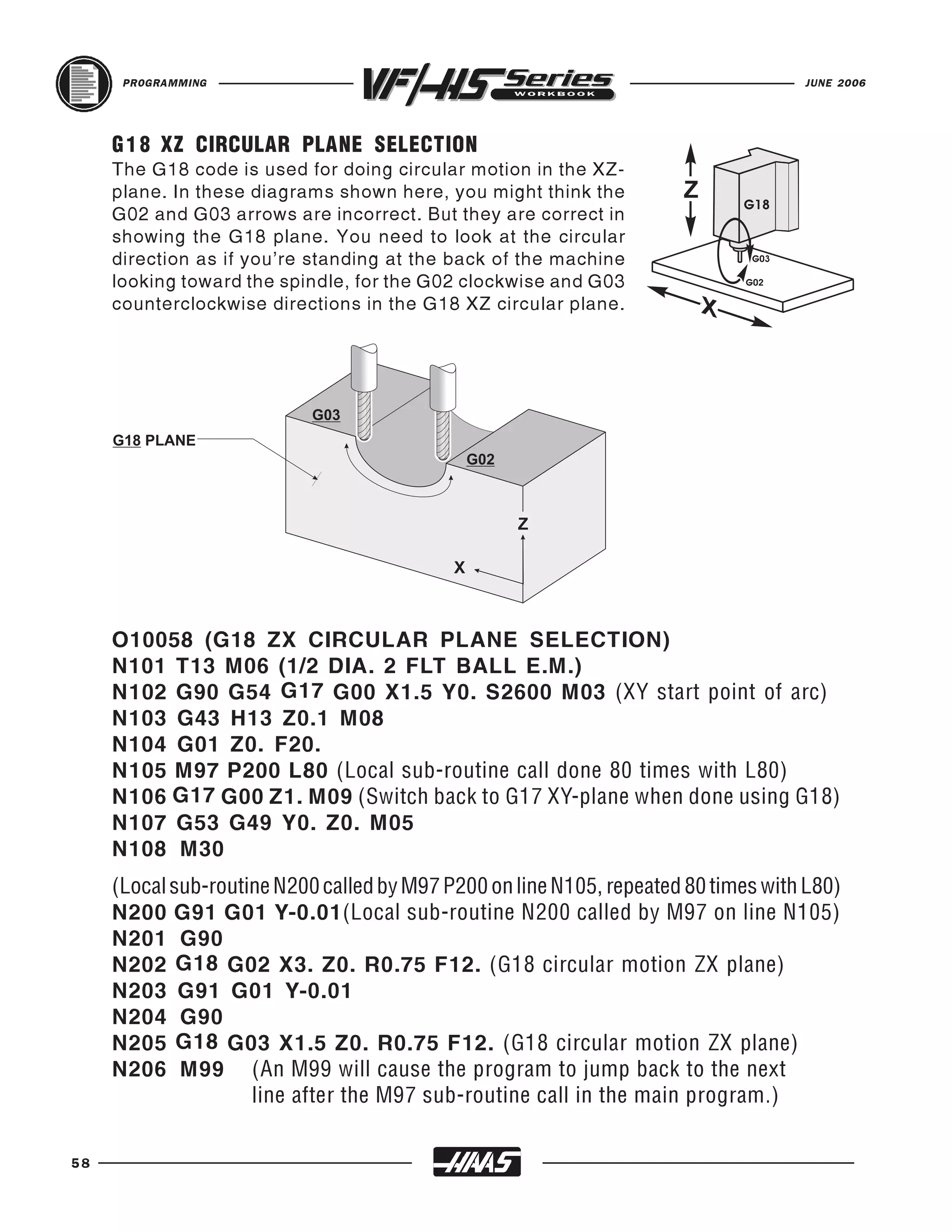
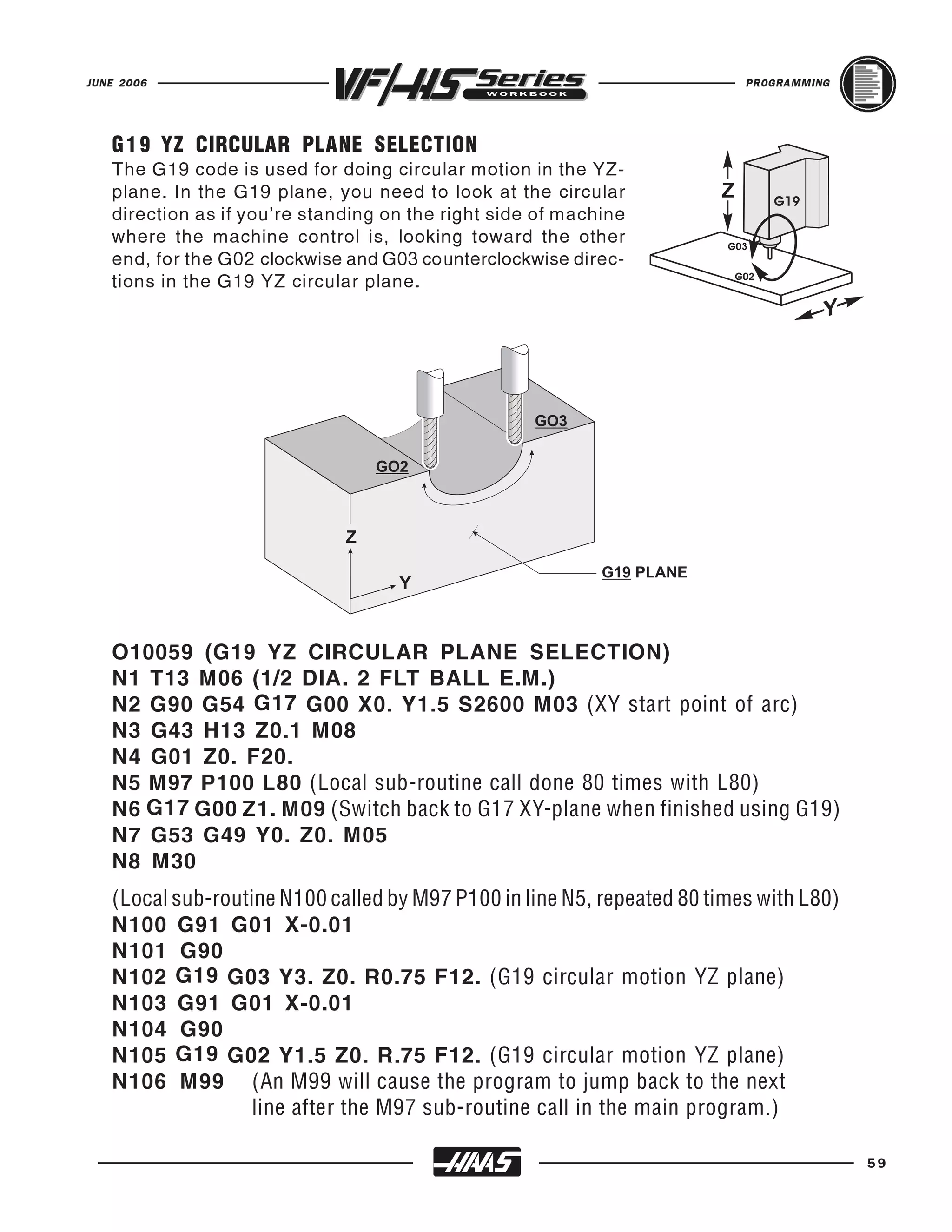
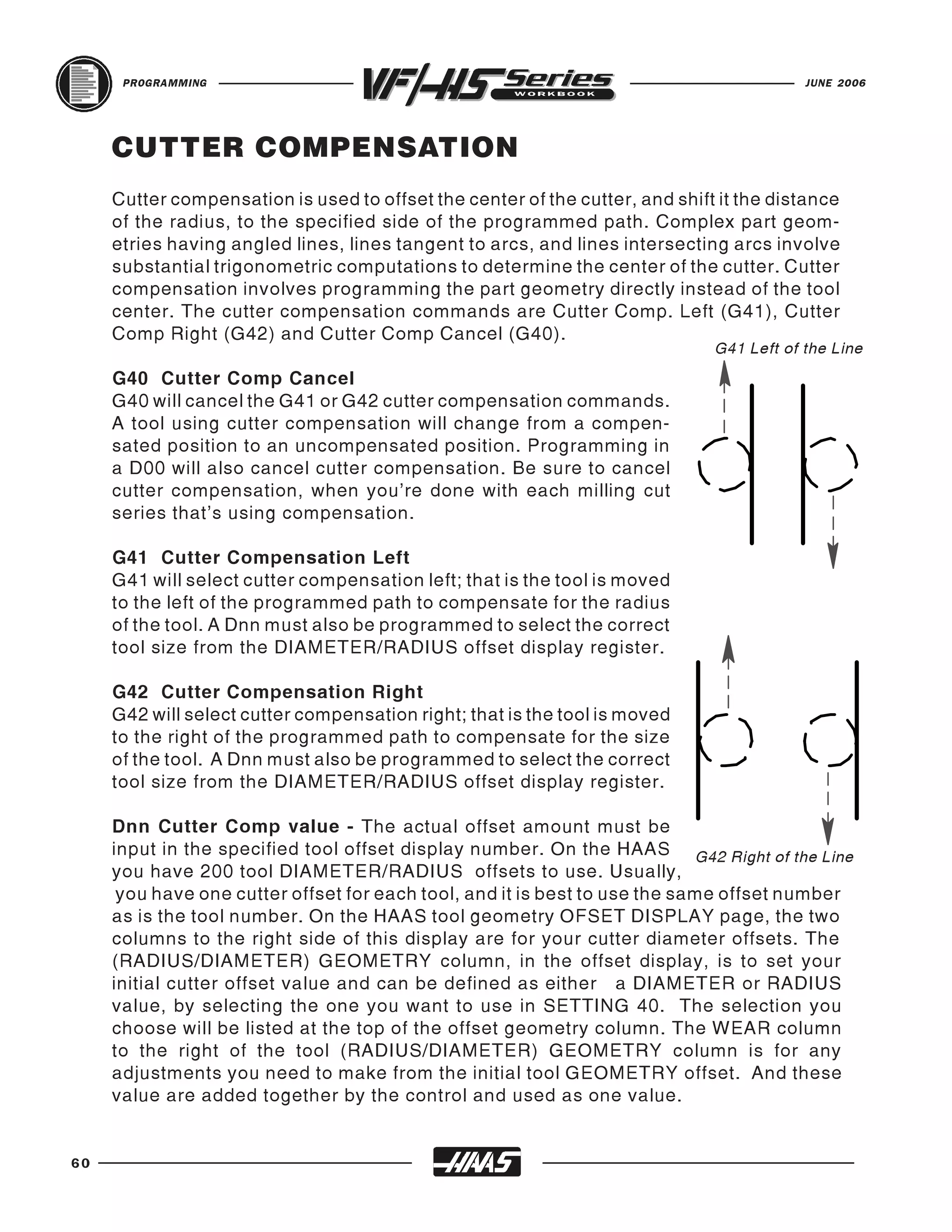
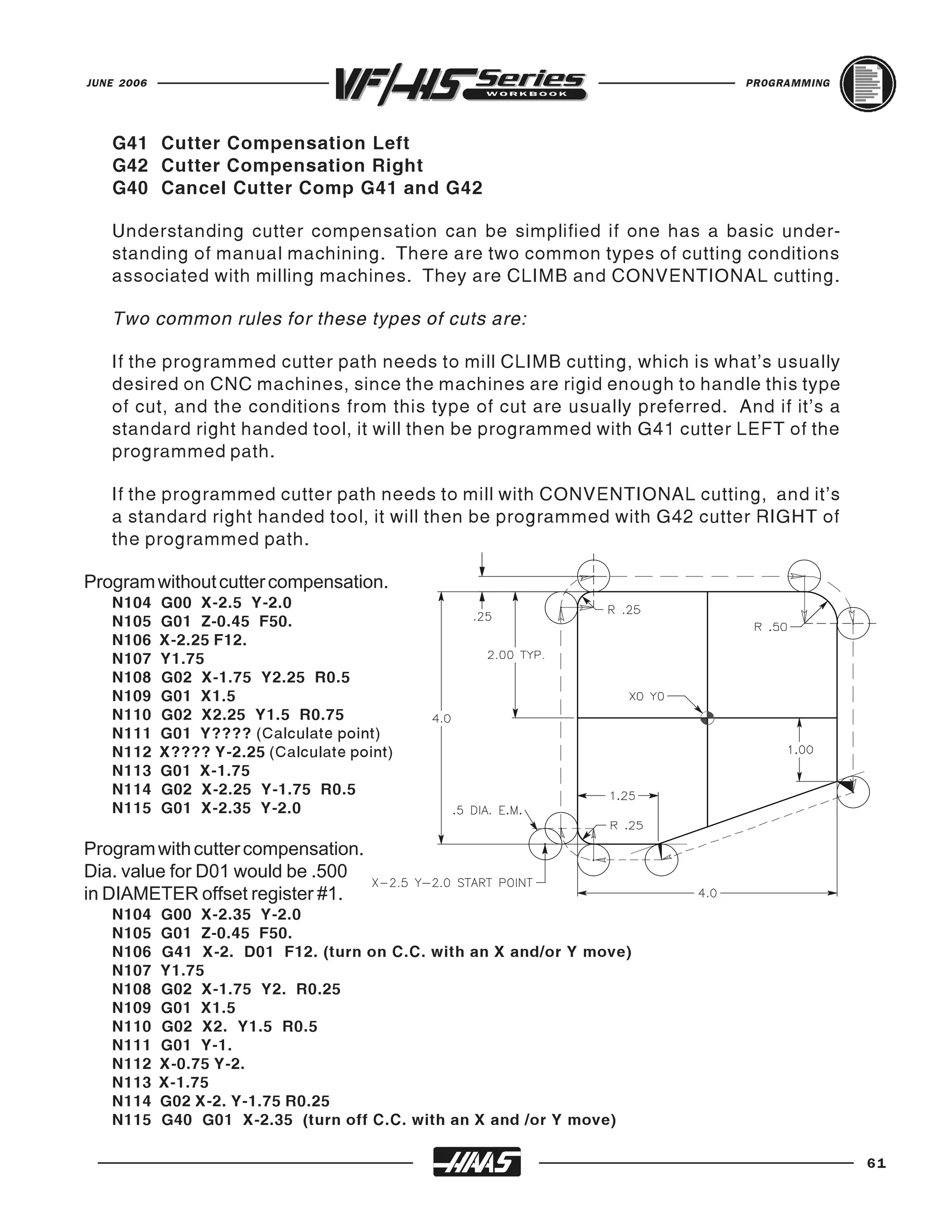
The document provides an overview of basic CNC programming principles including:
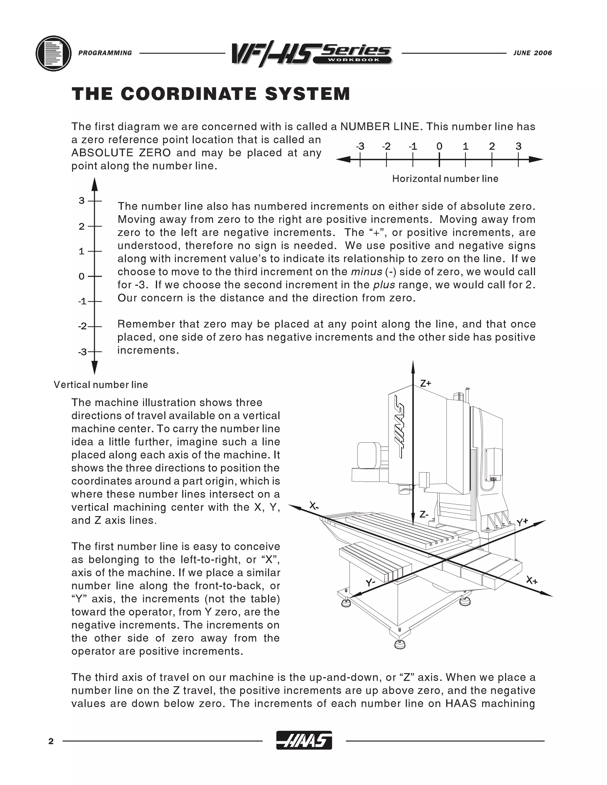
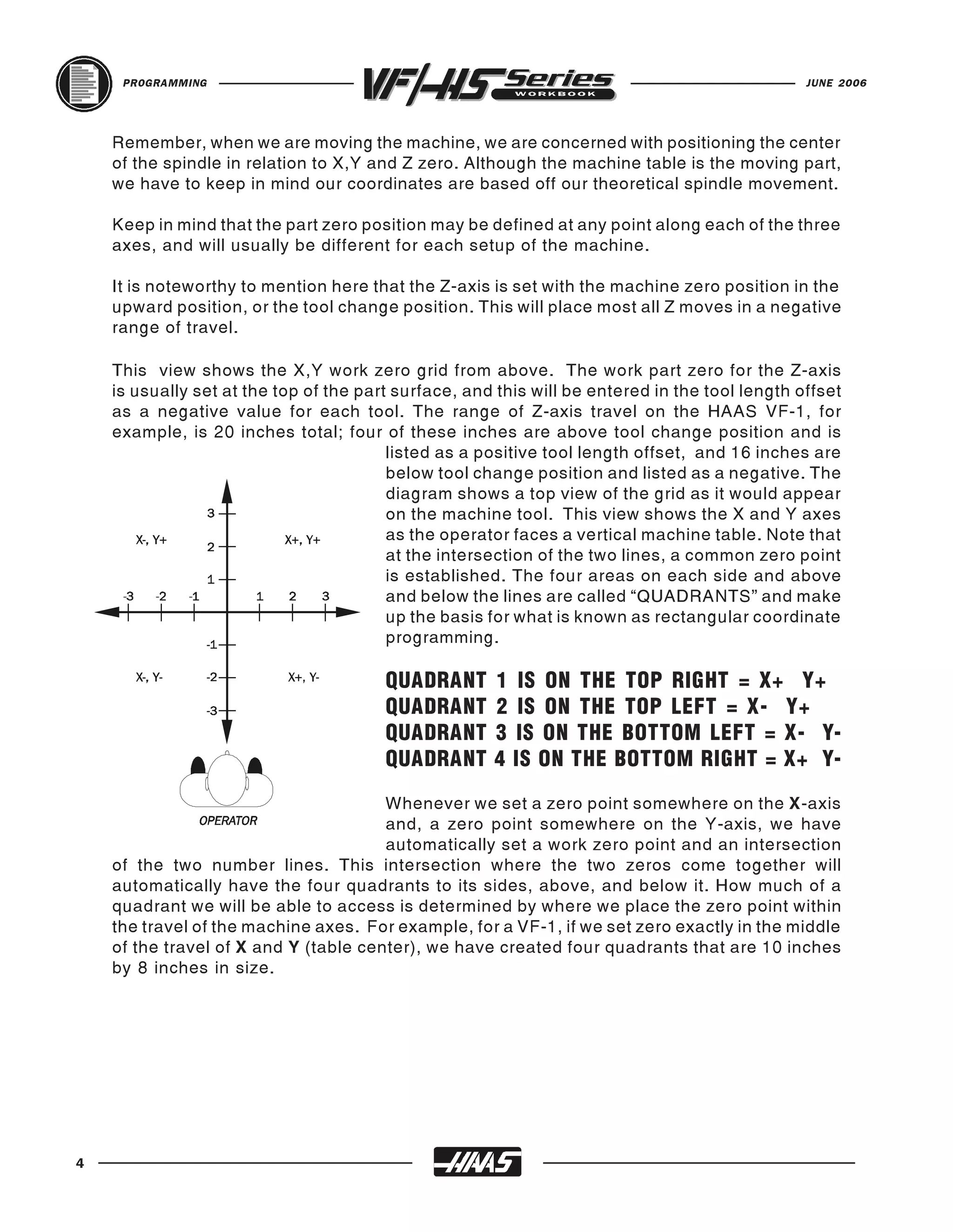
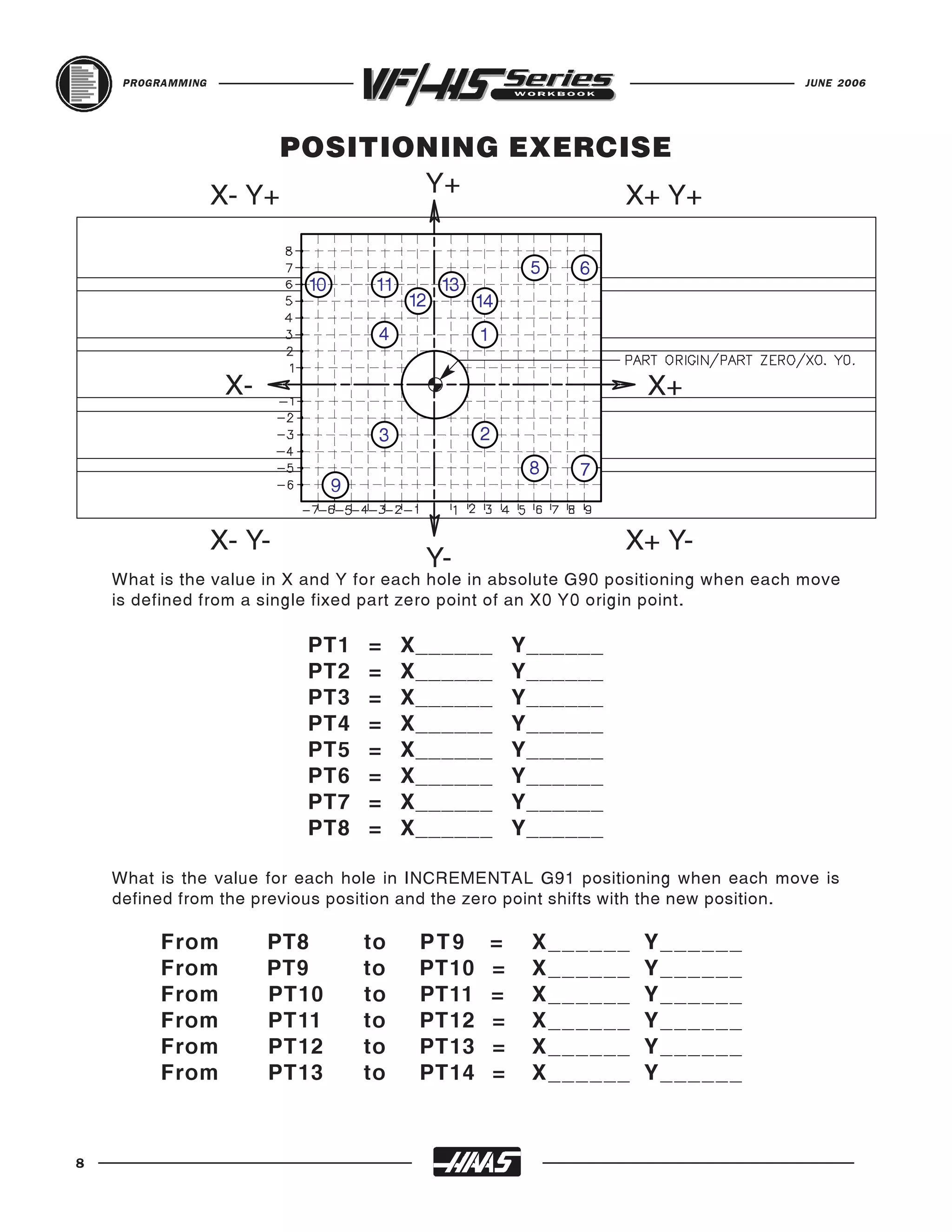
- Defining the machine coordinate system with X, Y, and Z axes and absolute zero point.
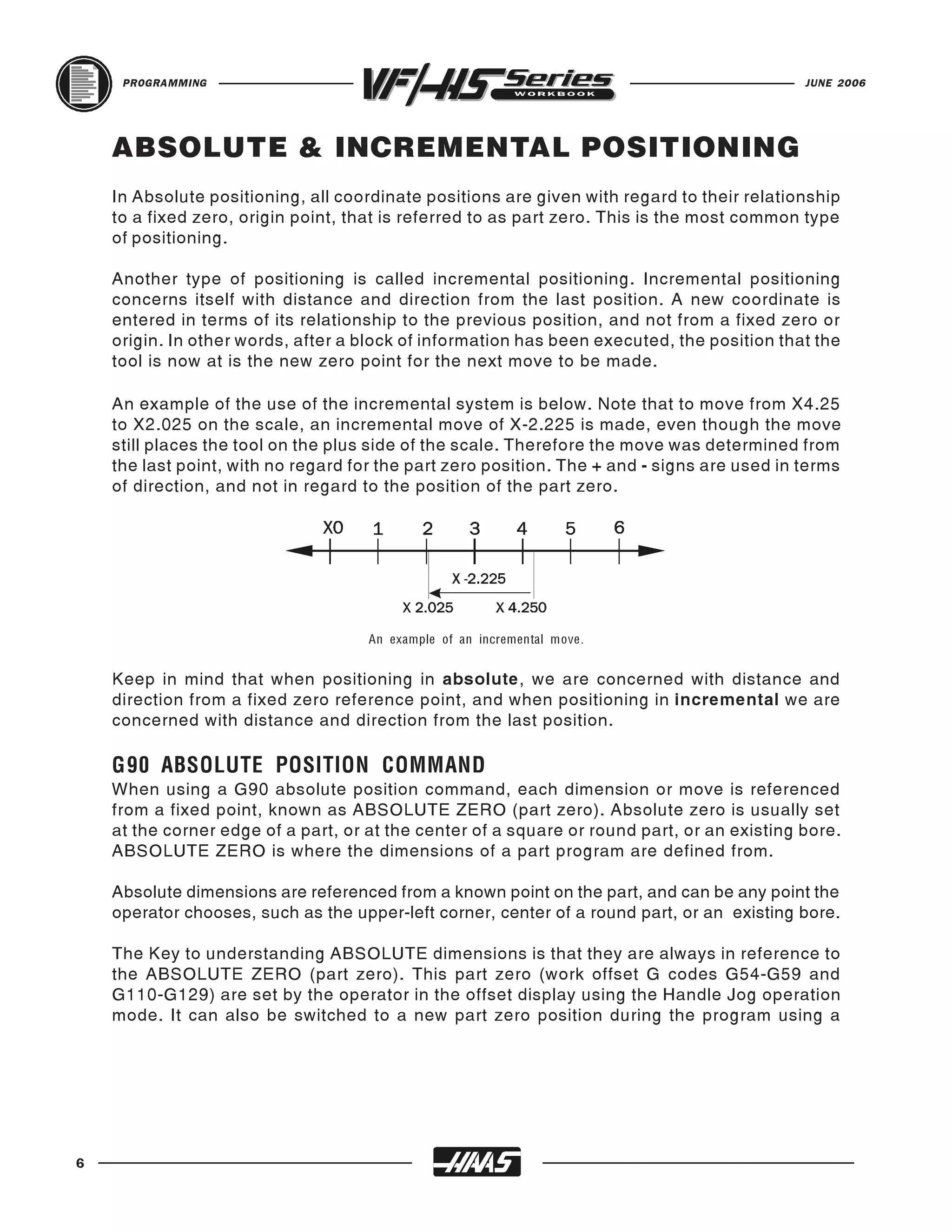
- Describing coordinate positioning as positive or negative increments from zero.
- Listing common Haas milling machine travels along the X, Y, and Z axes.