The document provides instructions for modeling the body of an F1 race car in SolidWorks. It involves creating several extruded cuts and a loft feature. Key steps include:
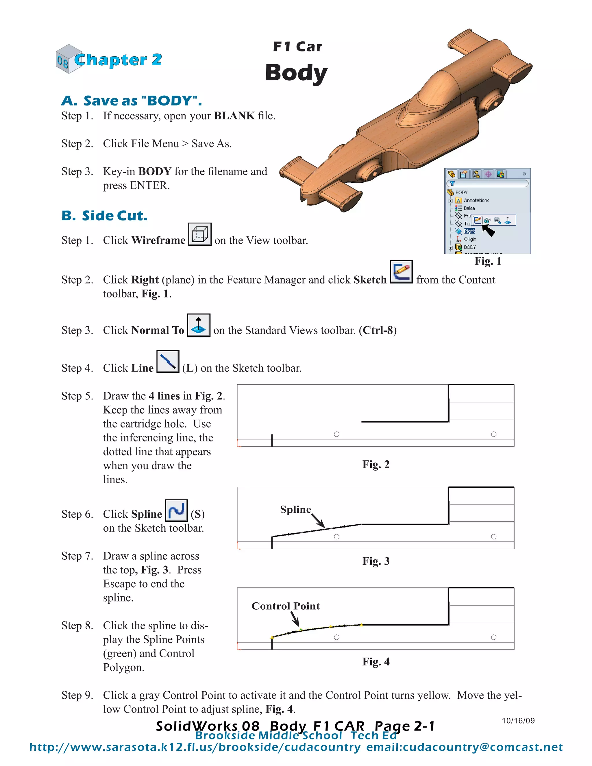
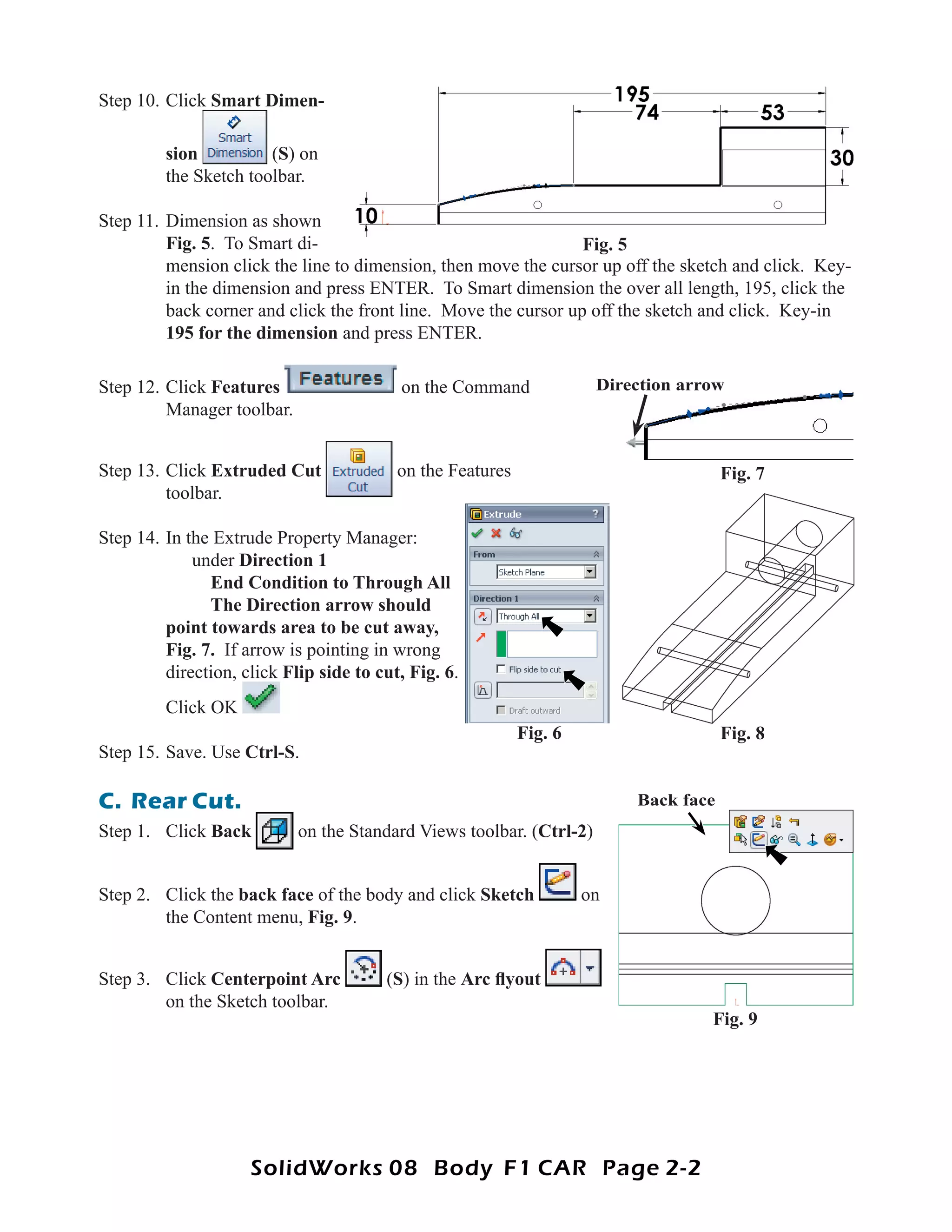
1) Creating a side cut by extruding a sketched profile.
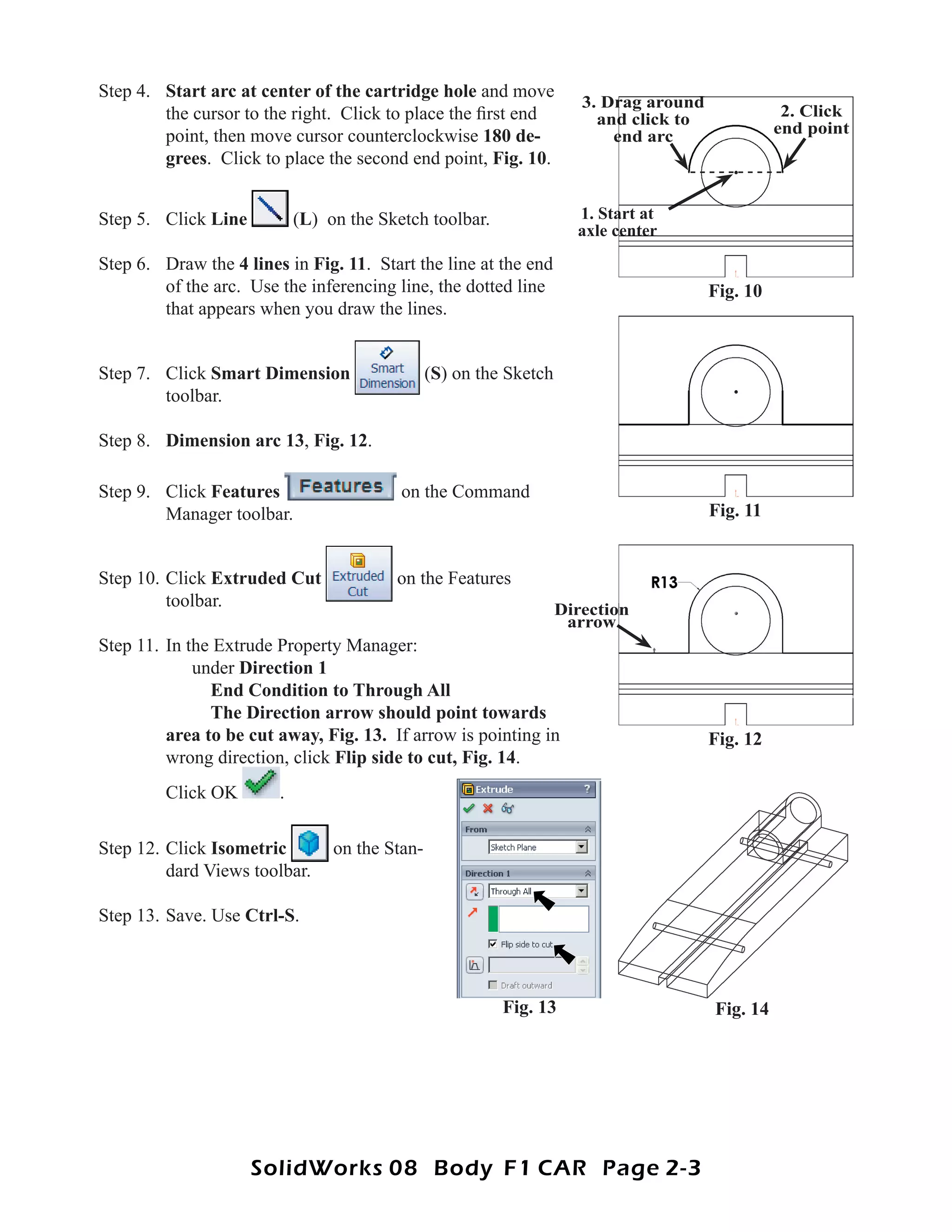
2) Adding a rear cut by extruding another sketched profile.
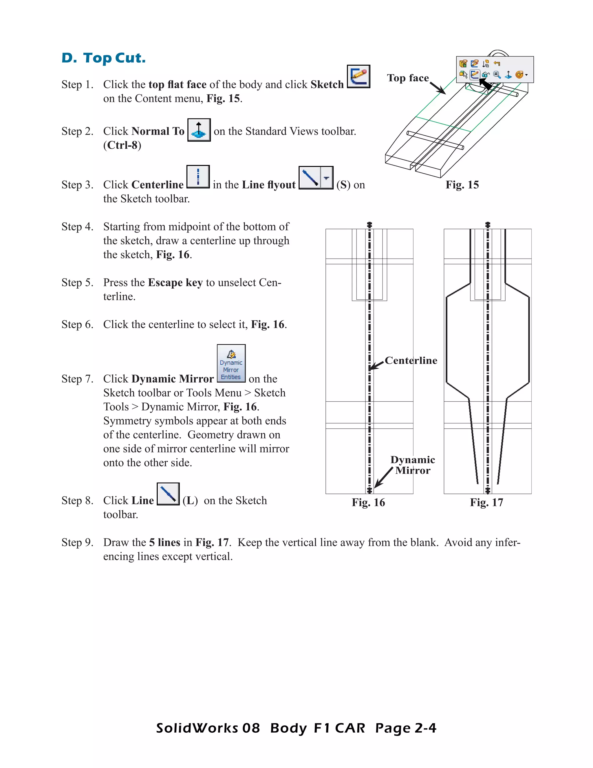
3) Cutting out the top of the body by extruding a mirrored sketch.
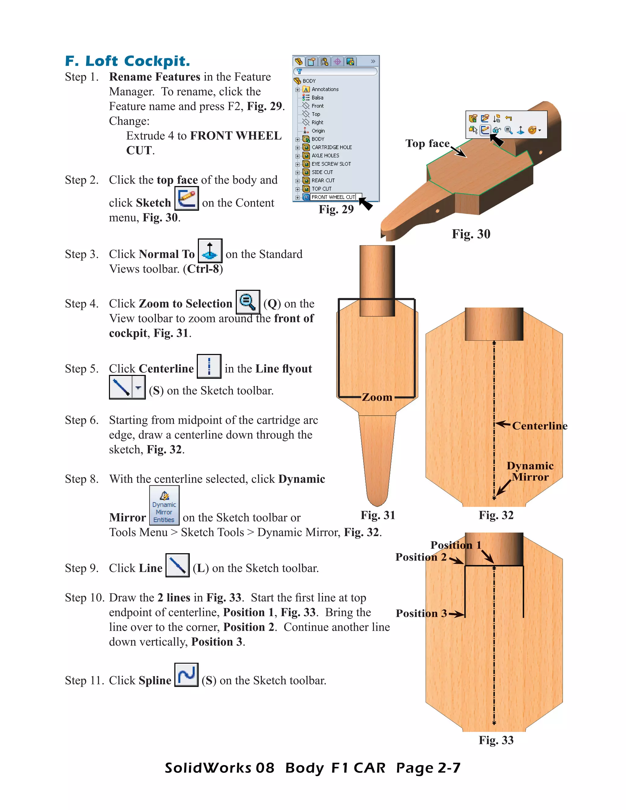
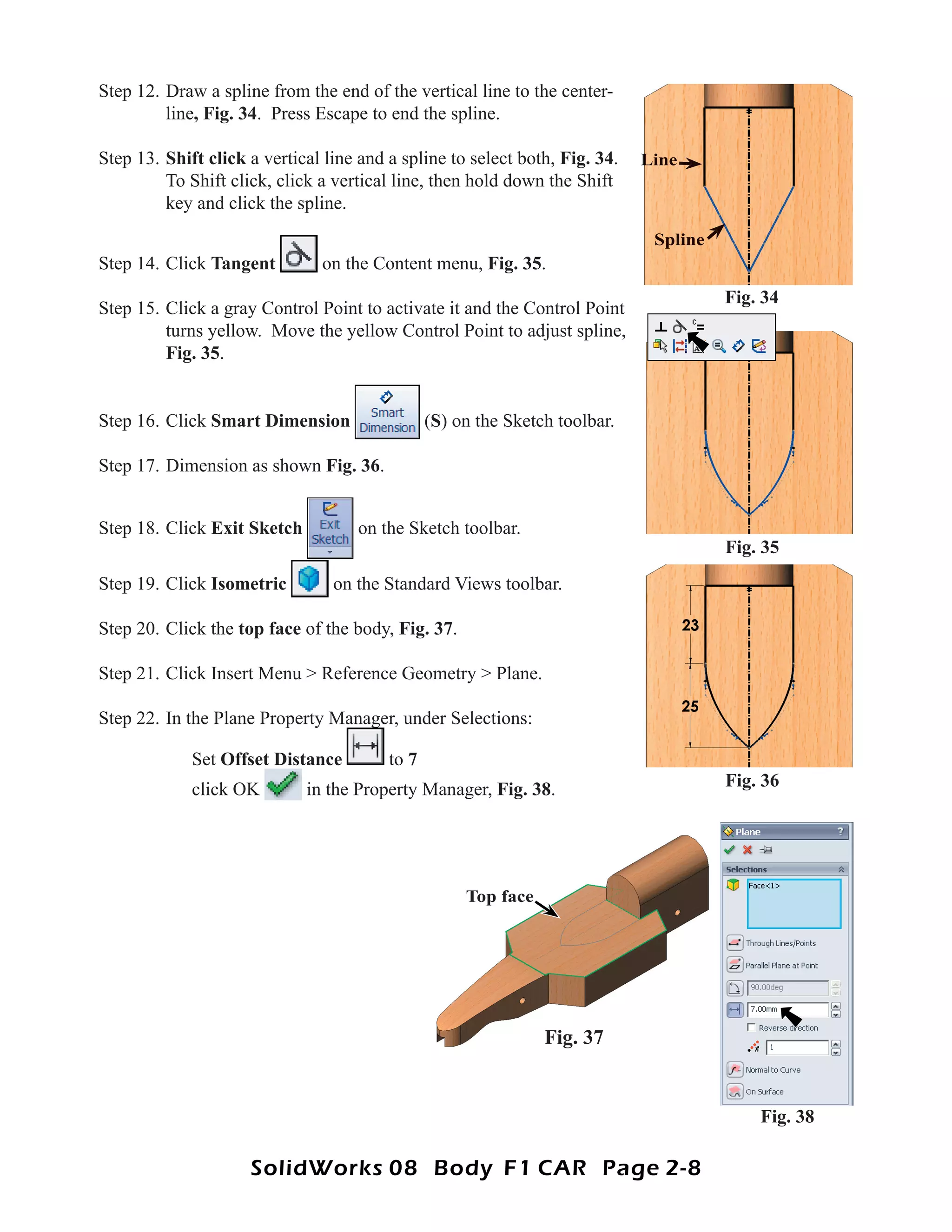
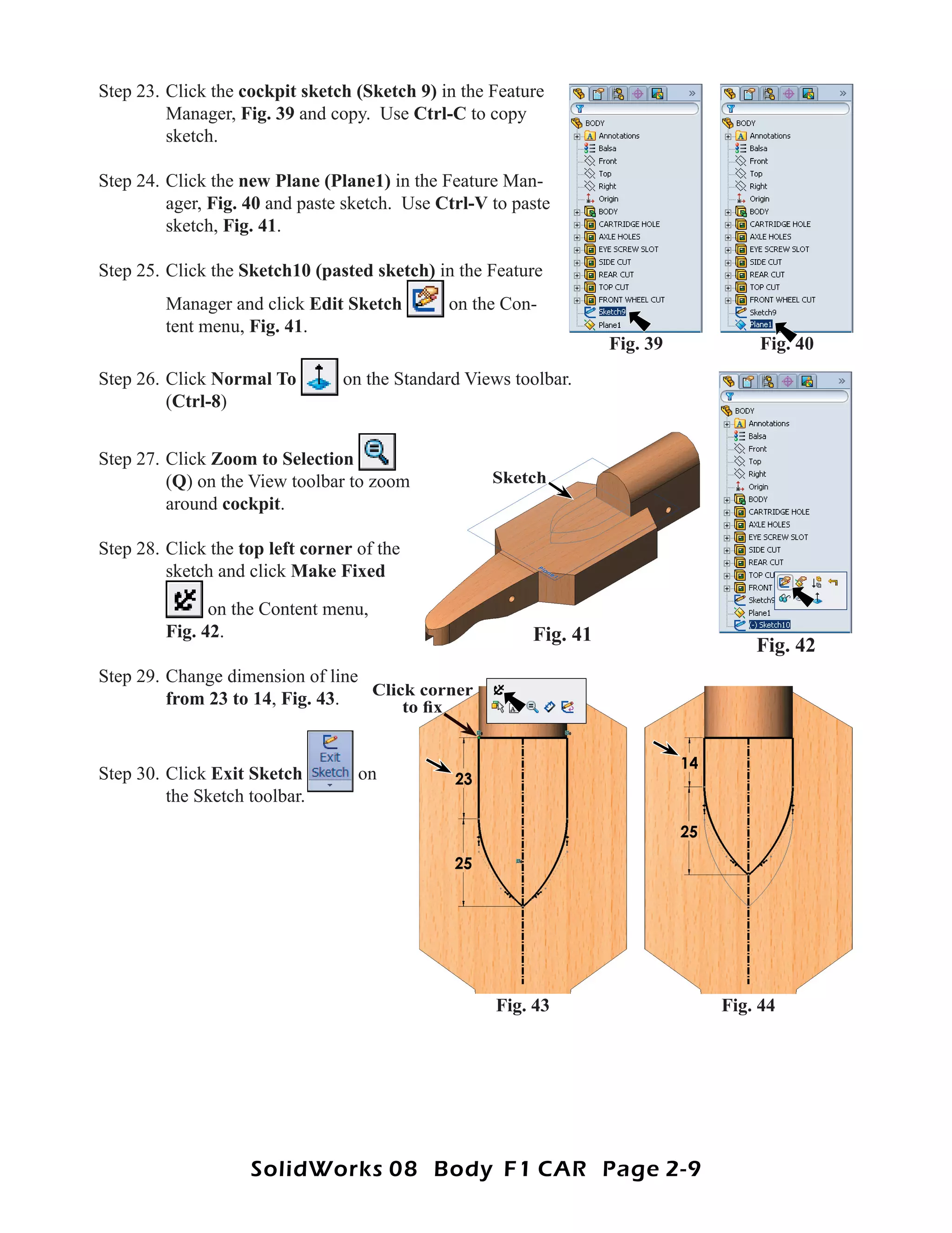
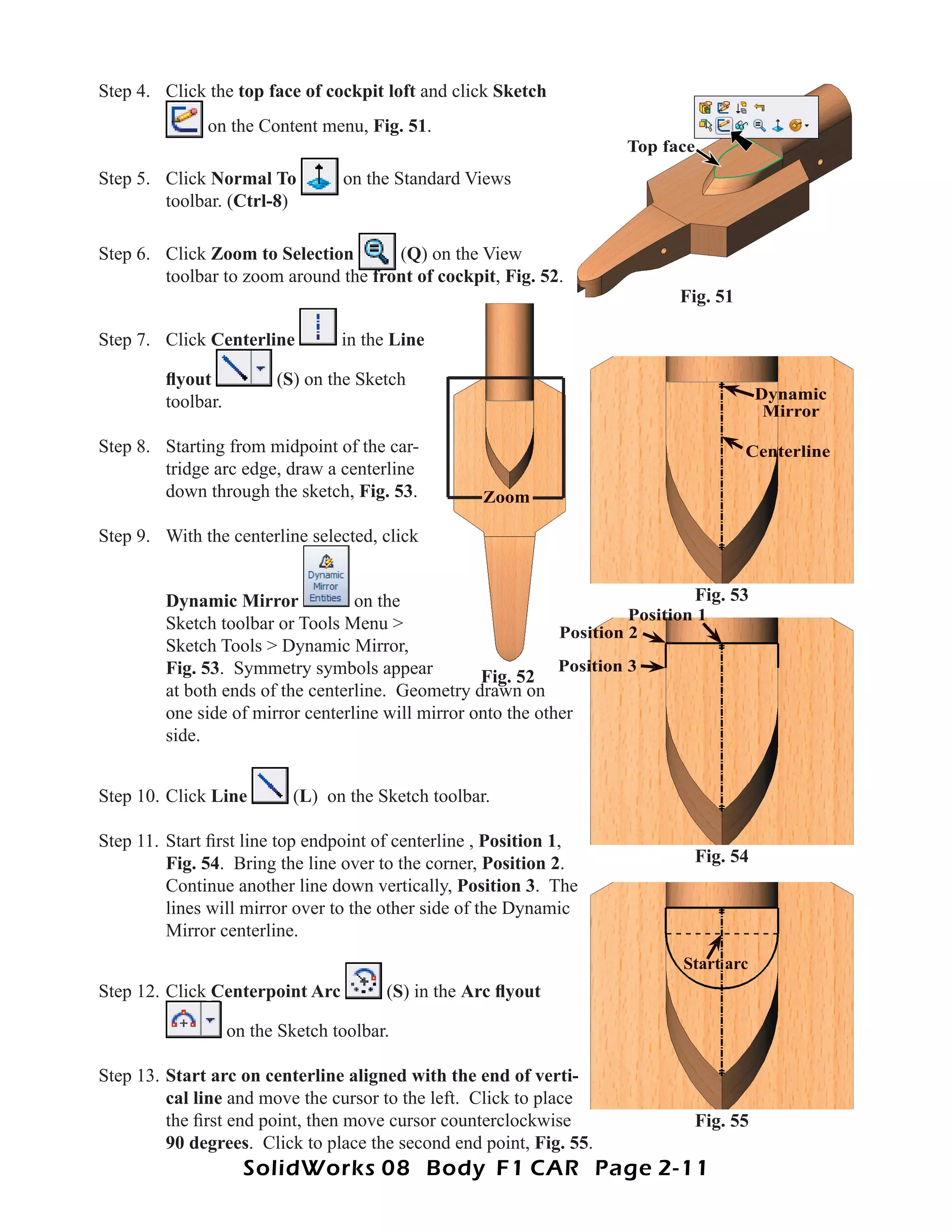
4) Using a loft to model the cockpit area between two sketches on different planes.
5) Adding more cuts and lofts to further define the body shape.