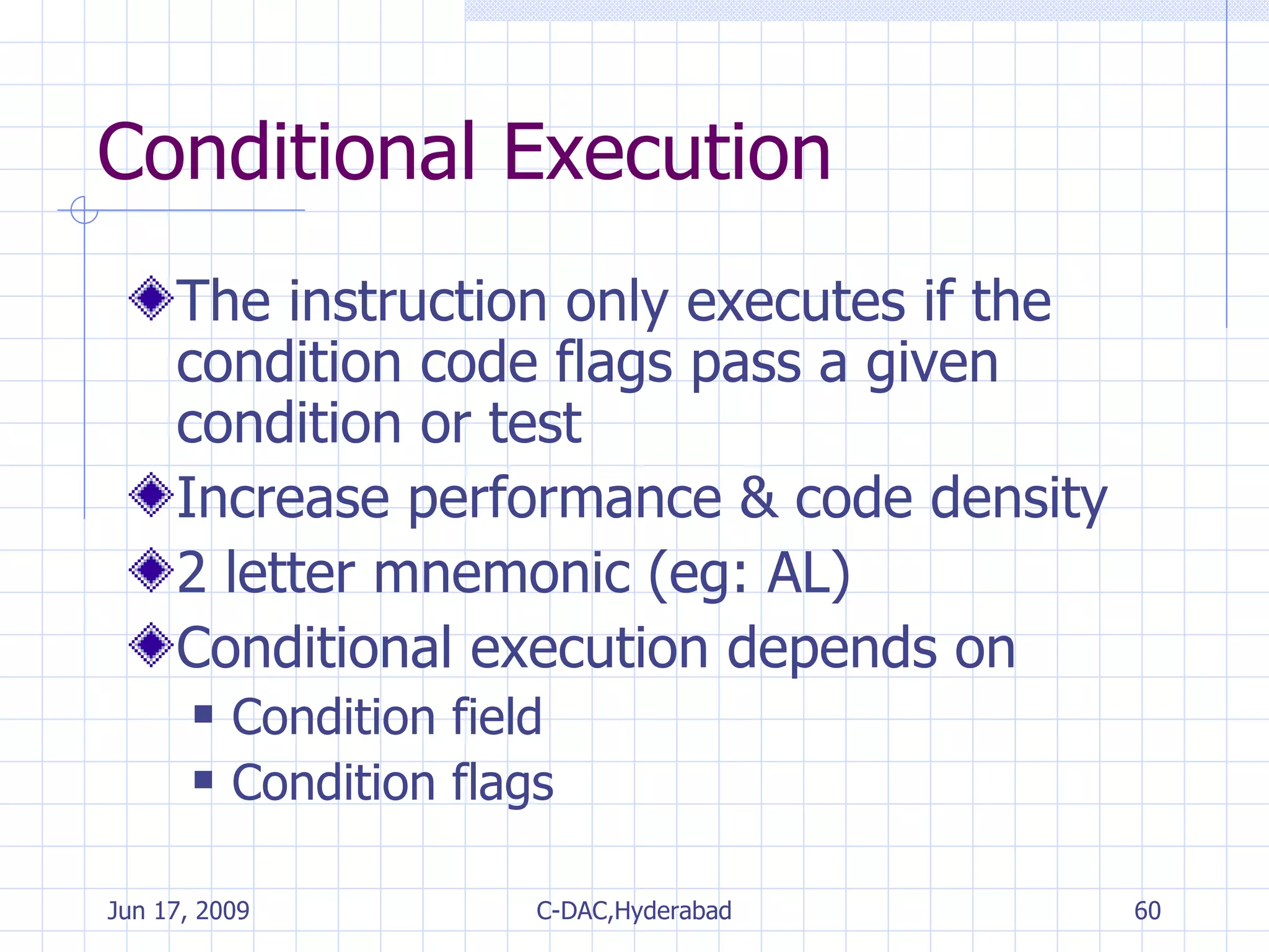
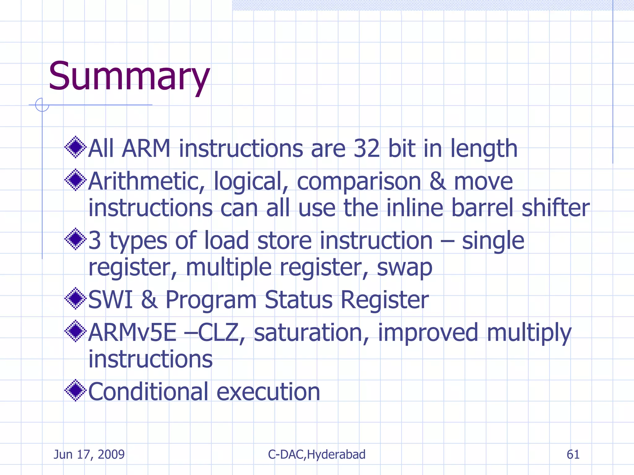
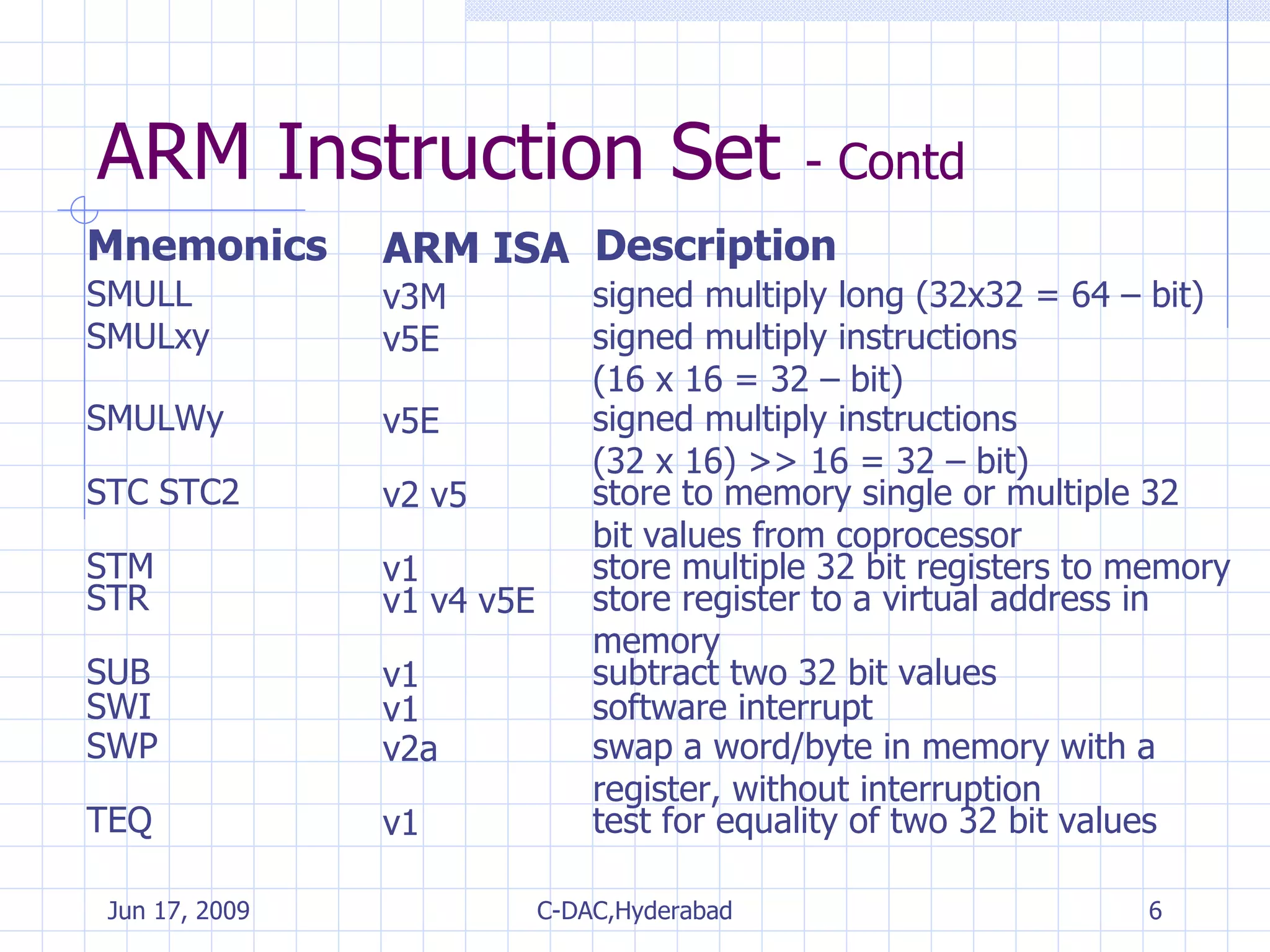
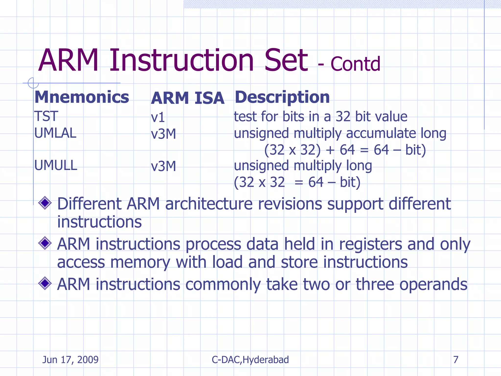
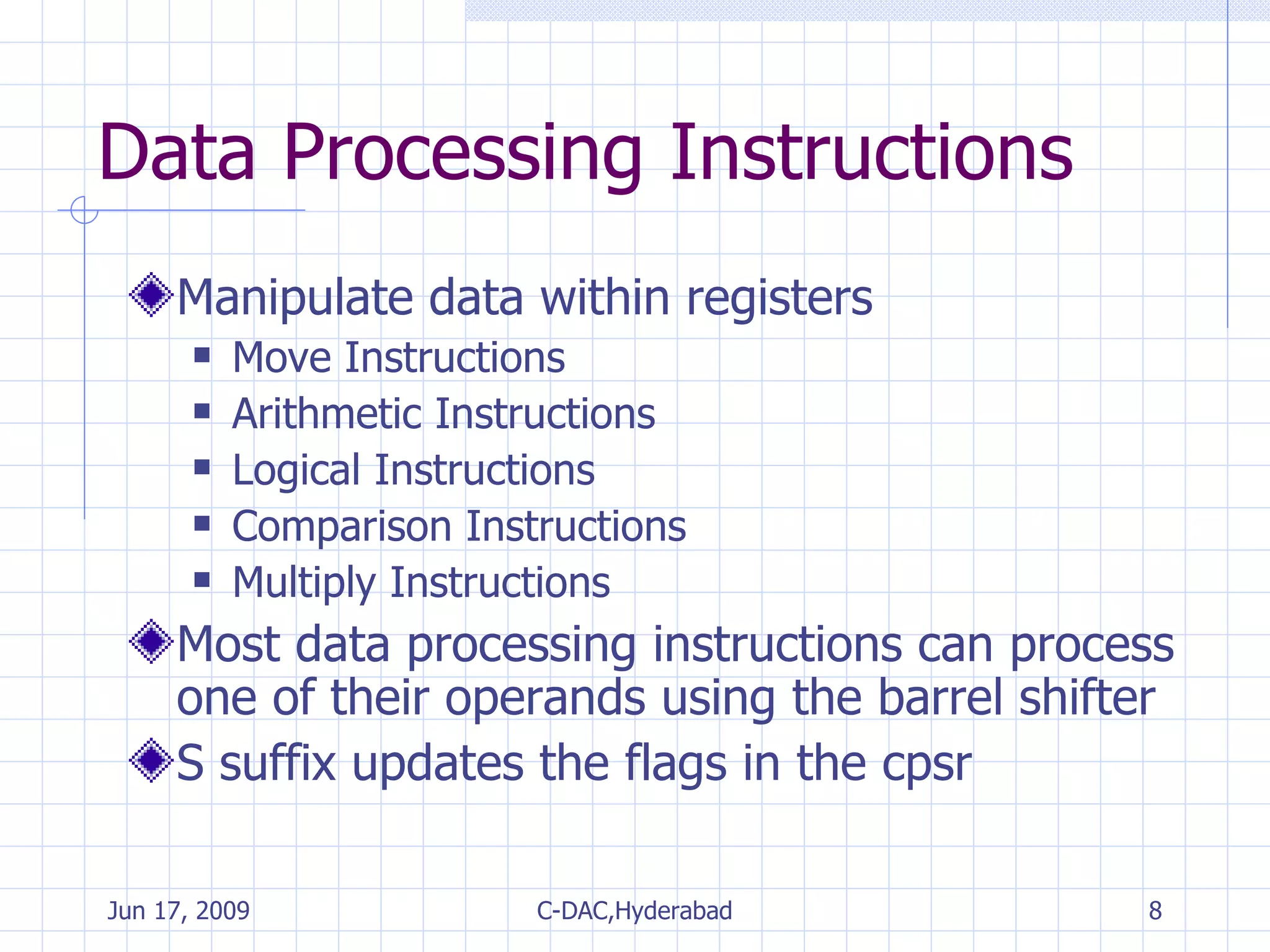
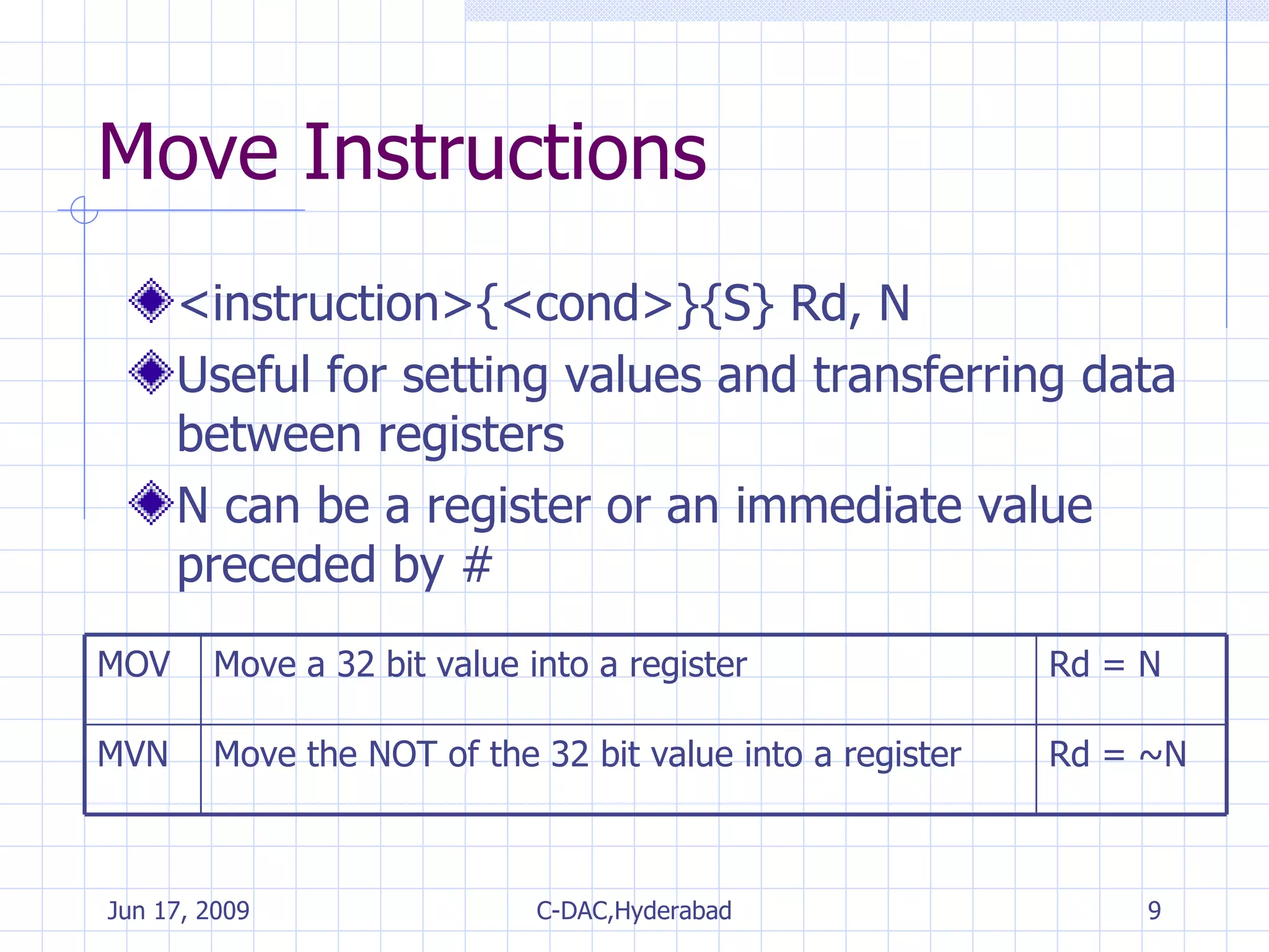
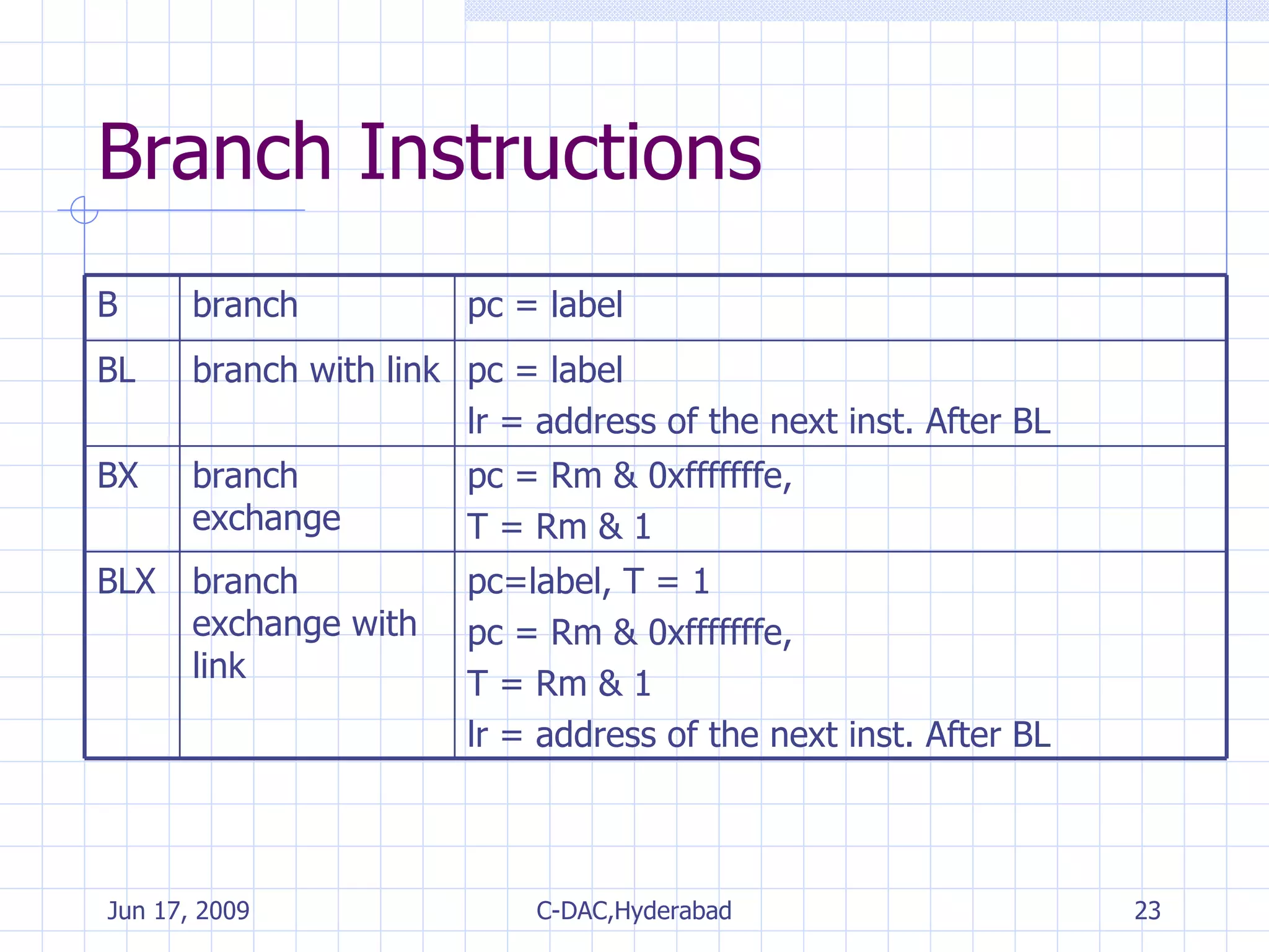
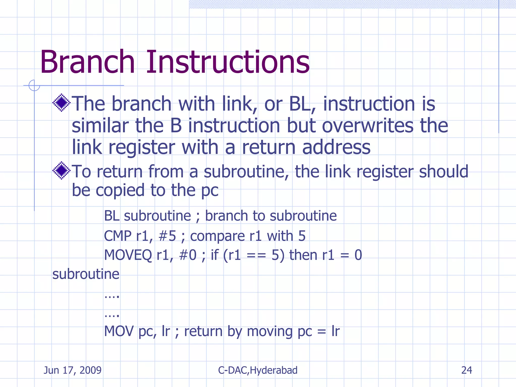
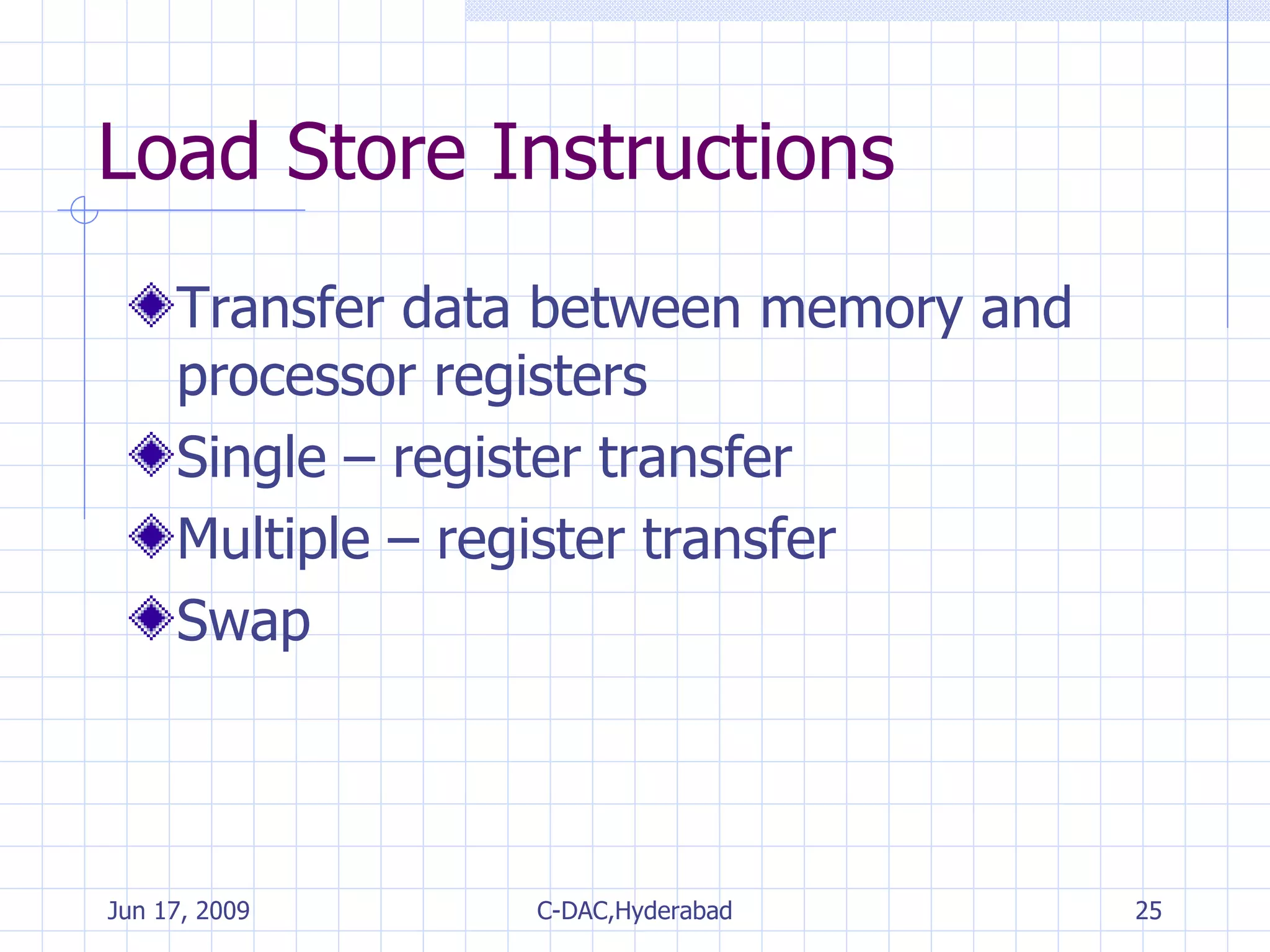
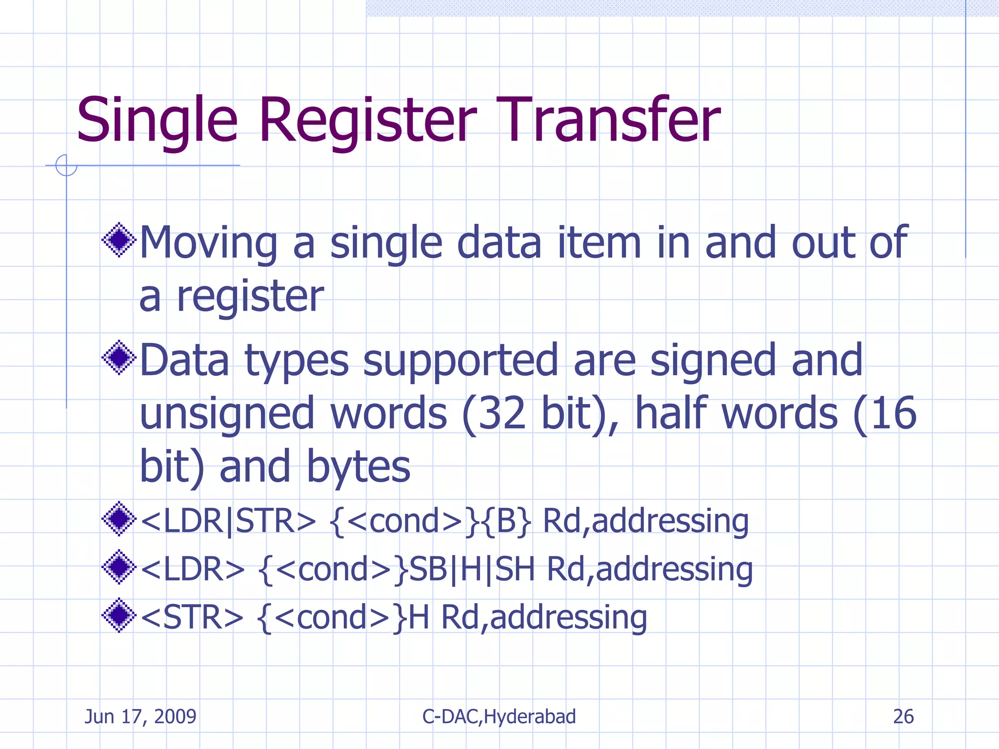
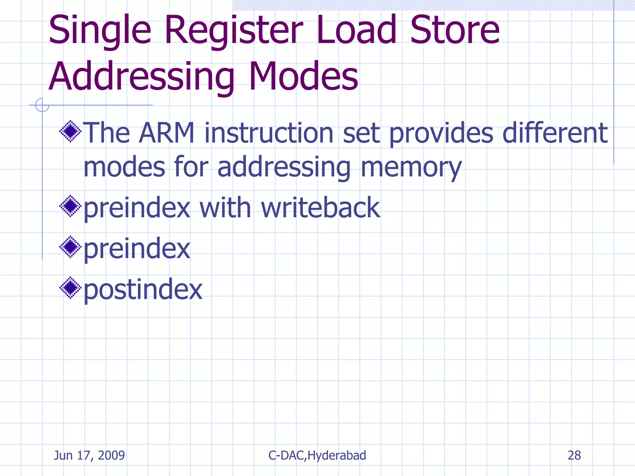
The document provides an overview of the ARM instruction set, including data processing, branch, load-store, and program status register instructions. It describes common instruction mnemonics and addressing modes. Key points covered include conditional execution, different instruction types for arithmetic, logical, comparison and multiply operations, and single and multiple register transfer instructions for moving data between registers and memory.
![Multiply Instructions MLA{<cond>}{S} Rd, Rm, Rs, Rn MUL{<cond>}{S} Rd, Rm, Rs instruction>{<cond>}{S} RdLo, RdHi, Rm, Rs Rd = Rm * Rs multiply MUL Rd = (Rm * Rs) + Rn multiply & accumulate MLA [RdHi,RdLo]=Rm * Rs unsigned multiply long UMULL [RdHi,RdLo]=[RdHi,RdLo] + (Rm * Rs) unsigned multiply accumulate long UMLAL [RdHi,RdLo]=(Rm * Rs) signed multiply long SMULL [RdHi,RdLo]=[RdHi,RdLo] + (Rm * Rs) signed multiply accumulate long SMLAL](https://image.slidesharecdn.com/arminstructionset-090617055544-phpapp01/75/ARM-Fundamentals-21-2048.jpg)
![Single Register Transfer Rd <-SignExtend (mem16[address]) load signed half word into a register LDRSH Rd <-SignExtend (mem8[address]) load signed byte into a register LDRSB Rd ->mem16[address] save half word from a register STRH Rd <-mem16[address] load half word into a register LDRH Rd ->mem8[address] save byte from a register STRB Rd <-mem8[address] load byte into a register LDRB Rd ->mem32[address] save byte or word from a register STR Rd <-mem32[address] load word into a register LDR](https://image.slidesharecdn.com/arminstructionset-090617055544-phpapp01/75/ARM-Fundamentals-27-2048.jpg)
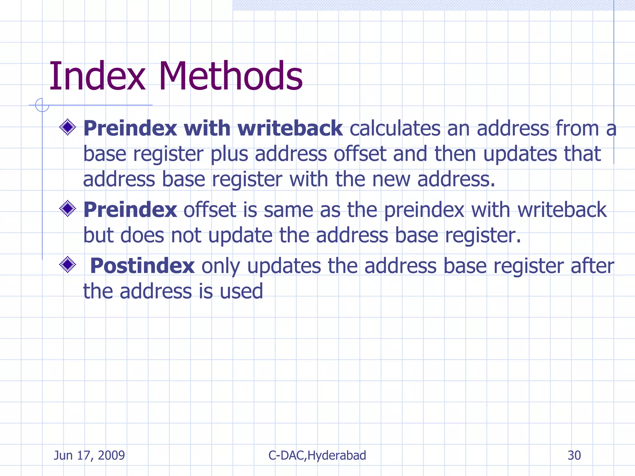
![Index Methods LDR r0, [r1], #4 base+ offset mem[base] postindex LDR r0, [r1, #4] not updated mem[base+offset] preindex LDR r0, [r1, #4]! base+ offset mem[base+offset] preindex with writeback Example Base Address Register Data Index Method](https://image.slidesharecdn.com/arminstructionset-090617055544-phpapp01/75/ARM-Fundamentals-29-2048.jpg)
![Single Register Load Store Addressing word or unsigned byte Addressing Mode & Index Method Addressing Syntax Preindex with immediate offset [Rn, #+/-offset_12] Preindex writeback with scaled register offset [Rn, +/-Rm, shift #shift_imm]! Preindex with register offset [Rn, +/-Rm] Preindex with scaled register offset [Rn, +/-Rm, shift #shift_imm] Preindex writeback with immediate offset [Rn, +/-offset_12]! Preindex writeback with register offset [Rn, +/-Rm]! Immediate postindexed [Rn], +/-offset_12 Register postindex [Rn], +/-Rm Scaled register postindex [Rn], +/-Rm, shift #shift_imm](https://image.slidesharecdn.com/arminstructionset-090617055544-phpapp01/75/ARM-Fundamentals-31-2048.jpg)
![Eg. of LDR instructions using different addressing modes Instruction r0= r1+= Preindexwith writeback LDR r0,[r1,#0x4]! mem32[r1+0x4] 0x4 Preindex Postindex LDR r0,[r1,r2]! mem32[r1+r2] r2 LDR r0,[r1,r2,LSR#0x4]! mem32[r1+(r2 LSR 0x4)] r2 LSR 0x4 LDR r0,[r1,#0x4] mem32[r1+0x4] not updated LDR r0,[r1,r2] mem32[r1+r2] not updated LDR r0,[r1,-r2,LSR#0x4] mem32[r1-(r2 LSR 0x4)] not updated LDR r0,[r1],#0x4 mem32[r1] 0x4 LDR r0,[r1],r2 mem32[r1] r2 LDR r0,[r1],r2,LSR#0x4 mem32[r1] R2 LSR 0x4](https://image.slidesharecdn.com/arminstructionset-090617055544-phpapp01/75/ARM-Fundamentals-32-2048.jpg)
![Variations of STRH instructions Instruction Result r1+= Preindexwith writeback STRH r0,[r1,#0x4]! mem16[r1+0x4] =r0 0x4 Preindex Postindex STRH r0,[r1,r2]! mem16[r1+r2] =r0 r2 STRH r0,[r1,#0x4]! mem16[r1+0x4] =r0 not updated STRH r0,[r1,r2] mem16[r1+r2] =r0 not updated STRH r0,[r1],#0x4 mem16[r1] =r0 0x4 STRH r0,[r1],r2 mem16[r1] =r0 r2](https://image.slidesharecdn.com/arminstructionset-090617055544-phpapp01/75/ARM-Fundamentals-33-2048.jpg)
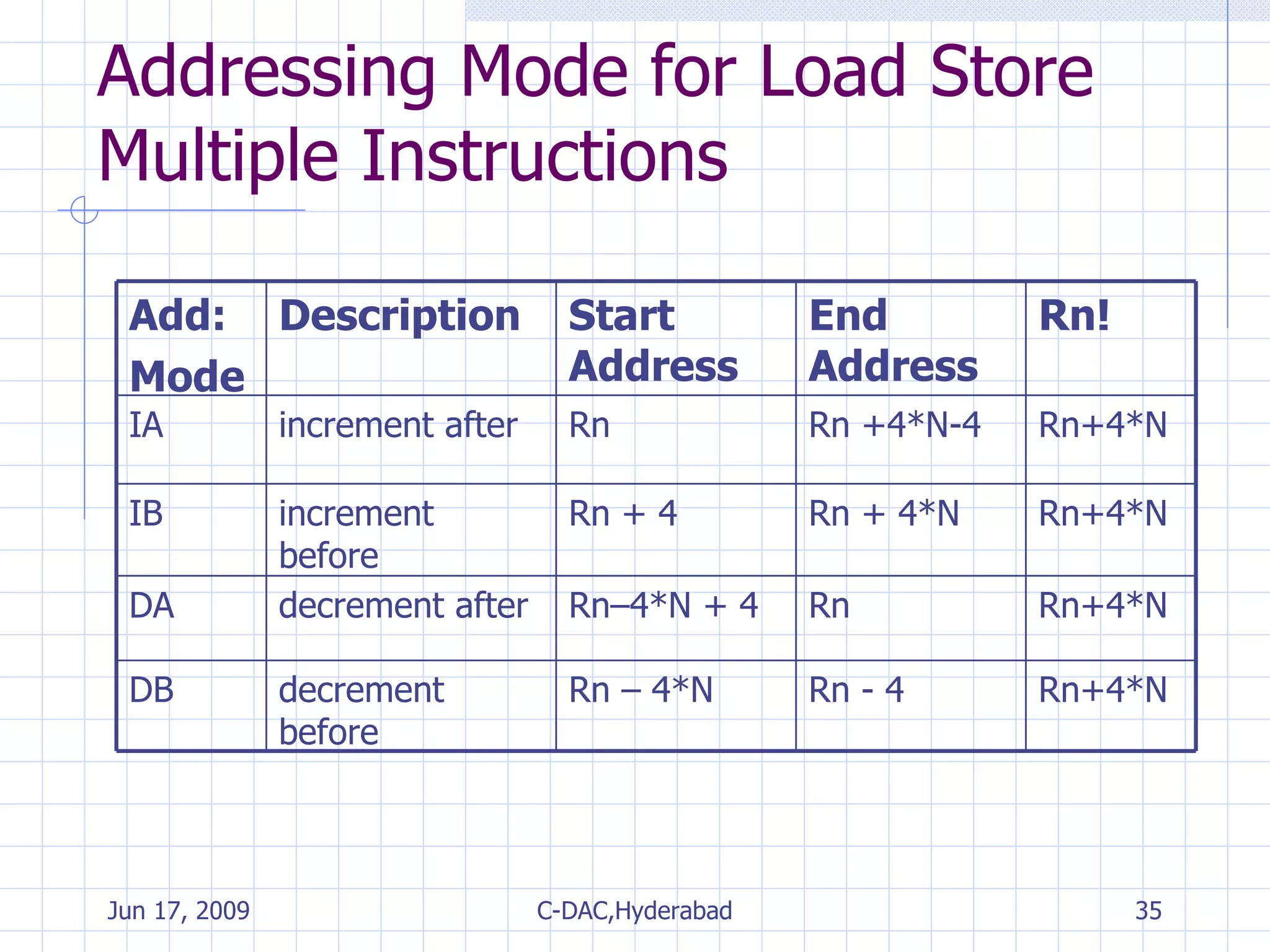
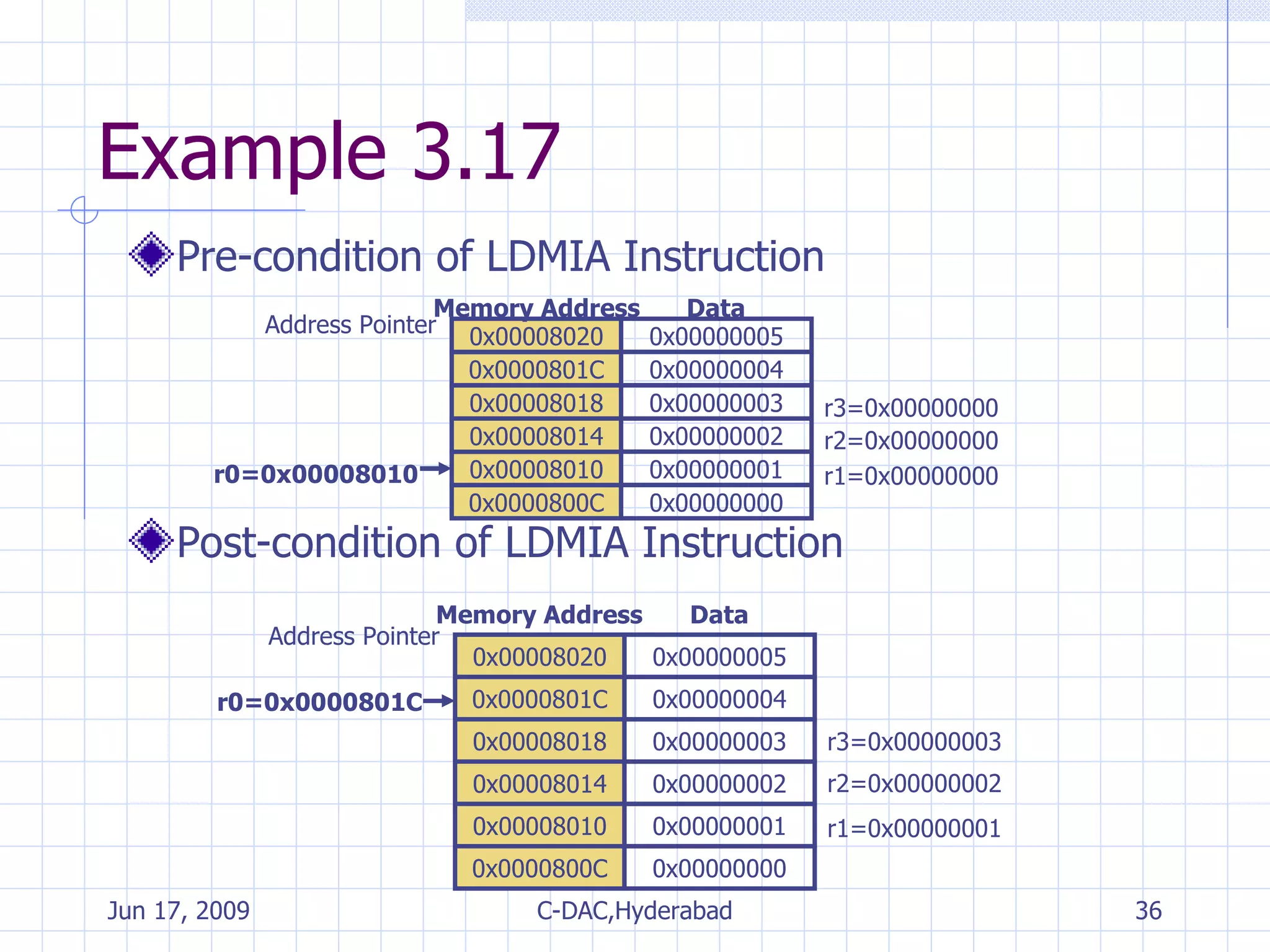
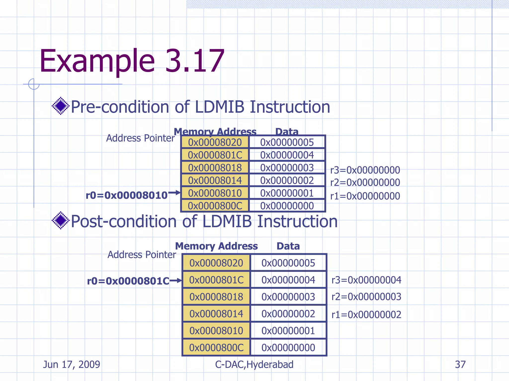
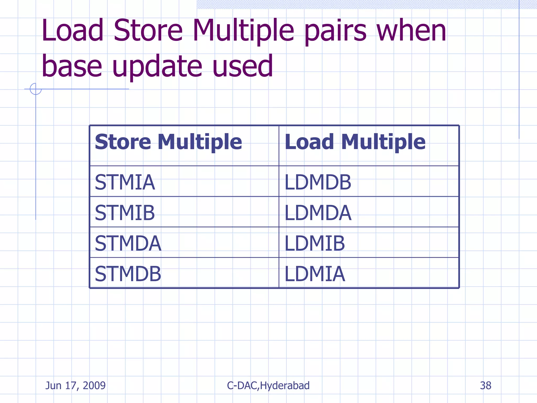
![Multiple Register Transfer Load–store multiple instructions can transfer multiple registers between memory and the processor in a single instruction. Moving blocks of data around memory and saving and restoring context stacks <LDM|STM>{<cond>}<addressing mode> Rn{!},<registers>{^} {Rd}*N -> mem32[start address + 4*N] optional Rn updated save multiple registers STM {Rd}*N <- mem32[start address + 4*N] optional Rn updated load multiple registers LDM](https://image.slidesharecdn.com/arminstructionset-090617055544-phpapp01/75/ARM-Fundamentals-34-2048.jpg)
![SWAP Instruction Swaps the contents of memory with the contents of a register Atomic operation– it reads and writes a location in the same bus operation,preventing any other instruction from reading or writing to that location until it completes. SWP{B}{<cond>} Rd, Rm, [Rn]](https://image.slidesharecdn.com/arminstructionset-090617055544-phpapp01/75/ARM-Fundamentals-44-2048.jpg)
![SWAP Instruction tmp=mem8[Rn] mem8[Rn]=Rm Rd=tmp swap a byte between memory and a register SWPB tmp=mem32[Rn] mem32[Rn]=Rm Rd=tmp swap a word between memory and a register SWP](https://image.slidesharecdn.com/arminstructionset-090617055544-phpapp01/75/ARM-Fundamentals-45-2048.jpg)
![Program Status Register Instructions 2 instructions to directly control a psr MRS - transfers the contents of cpsr or spsr into a register MSR - transfers the contents of register into cpsr or spsr N Z C V I F T Mode 31 30 29 28 7 6 5 4 0 Condition Flags Processor Mode Interrupt Masks Thumb State Function Bit Fields Flags[24:31] Status[16:23] Extension[8:15] Control[0:7]](https://image.slidesharecdn.com/arminstructionset-090617055544-phpapp01/75/ARM-Fundamentals-47-2048.jpg)
![Program Status Register Instructions MRS{<cond>} Rd,<cpsr|spsr> MSR{<cond>} <cpsr|spsr>_<fields>,Rm MSR{<cond>} <cpsr|spsr>_<fields>,#immediate psr[field] = immediate move an immediate value to a psr MSR psr[field] = Rm move gpr to a psr MSR Rd = psr copy psr to a gpr MRS](https://image.slidesharecdn.com/arminstructionset-090617055544-phpapp01/75/ARM-Fundamentals-48-2048.jpg)
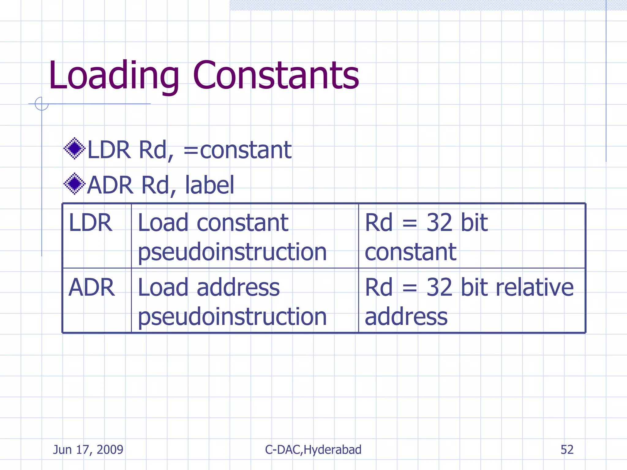
![Loading Constants LDR r0, [pc,#offset_12] LDR r0, =0x55555555 MOV r0, #0xff LDR r0, =0xff Actual instruction Pseudo instruction](https://image.slidesharecdn.com/arminstructionset-090617055544-phpapp01/75/ARM-Fundamentals-53-2048.jpg)
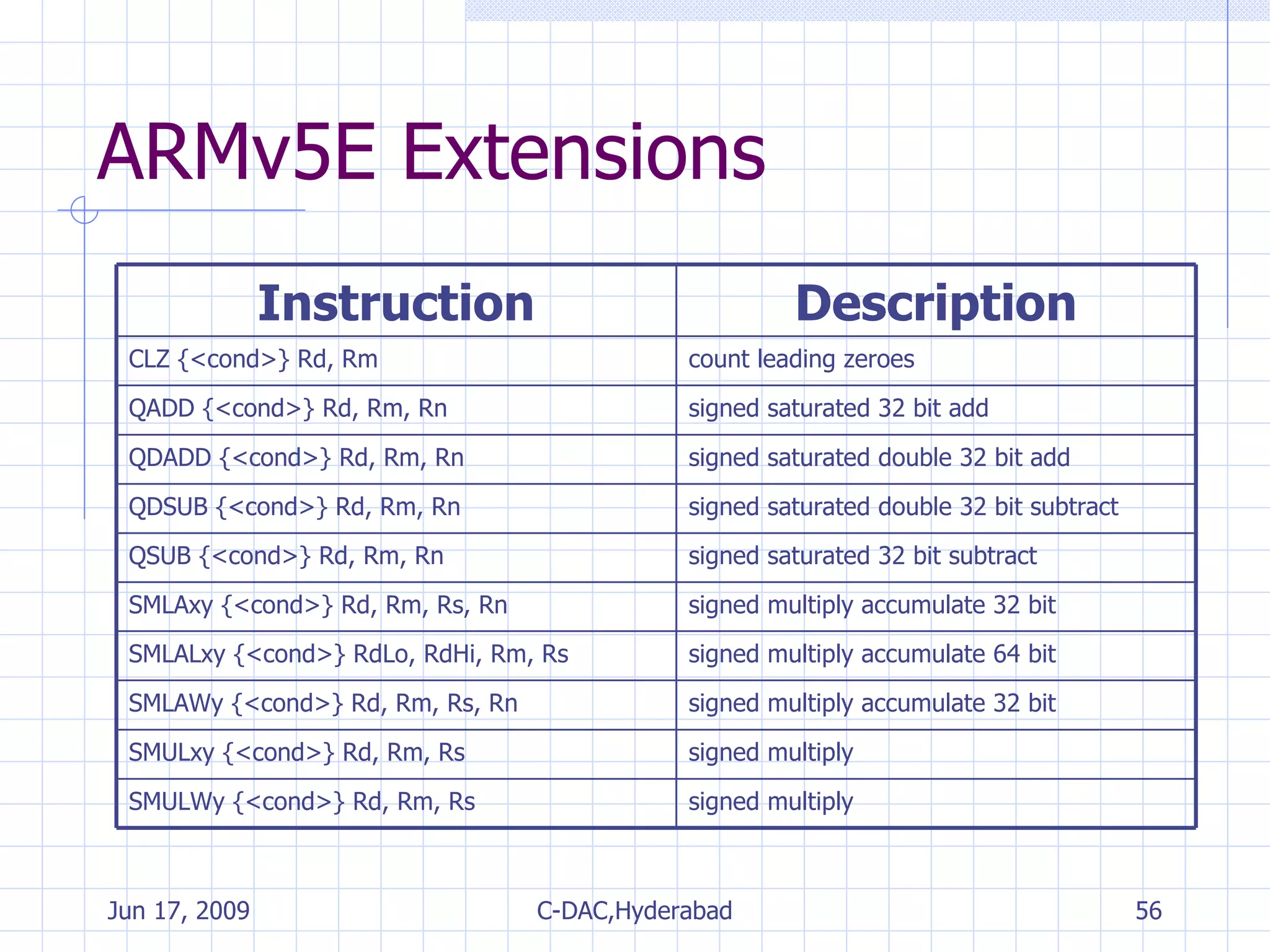
![ARMv5.E Multiply Instructions Instruction Signed Multiply [Accumulate] Signed Result Q Flag updated Calculation SMLAxy (16-bit*16-bit)+32-bit 32-bit yes Rd=(Rm.x*Rs.y)+Rn SMLALxy (16-bit*16-bit)+64-bit 64-bit - [RdHi,RdLo]+= Rm.x*Rs.y SMLAWxy ((32-bit*16-bit) >>16) +32-bit 32-bit yes Rd=((Rm*Rs.y) >>16) +Rn SMULxy (16-bit*16-bit) 32-bit - Rd=Rm.x*Rs.y SMULWy ((32-bit*16-bit) >>16) 32-bit - Rd=(Rm*Rs.y) >>16 x and y select which 16 bits of a 32 bit register are used for the first and second operands T for the top 16 bits and B for the bottom 16 bits SMLATB r4, r1, r2, r3 r4 = (r1.T * r2.B) + r3](https://image.slidesharecdn.com/arminstructionset-090617055544-phpapp01/75/ARM-Fundamentals-59-2048.jpg)