Downloaded 721 times


The document discusses the mechanical design of overhead power lines. It describes the main components of overhead lines which include conductors, supports, insulators, and cross arms. Conductors carry electric power and are made of materials like copper, aluminum, and steel that have high conductivity and strength. Supports can be wooden poles, steel poles, or lattice towers and must withstand mechanical loads. Insulators provide insulation between conductors and supports to prevent leakage currents. The document also covers factors that affect overhead line design like line voltage, conductor spacing, and methods to reduce corona effects like increasing conductor size.
Introduction to overhead lines, their advantages over underground cables, and the importance of mechanical safety.
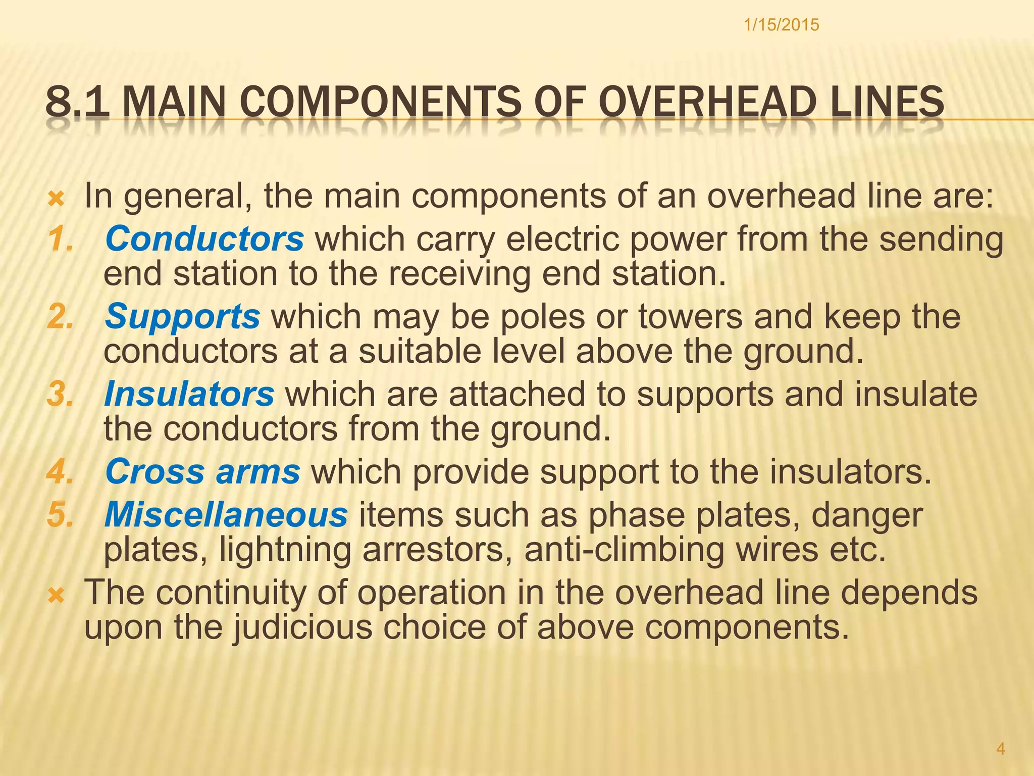
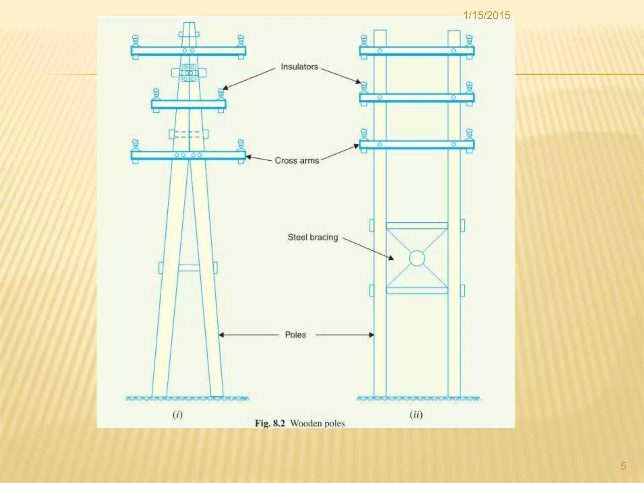
Overview of key components including conductors, supports, insulators, cross arms, and additional items affecting operational continuity.
Characteristics of optimal conductor materials: high conductivity, tensile strength, low cost. Common materials include copper, aluminum.
Discussion on supports like poles and towers with properties such as strength, cost-effectiveness and maintenance accessibility.
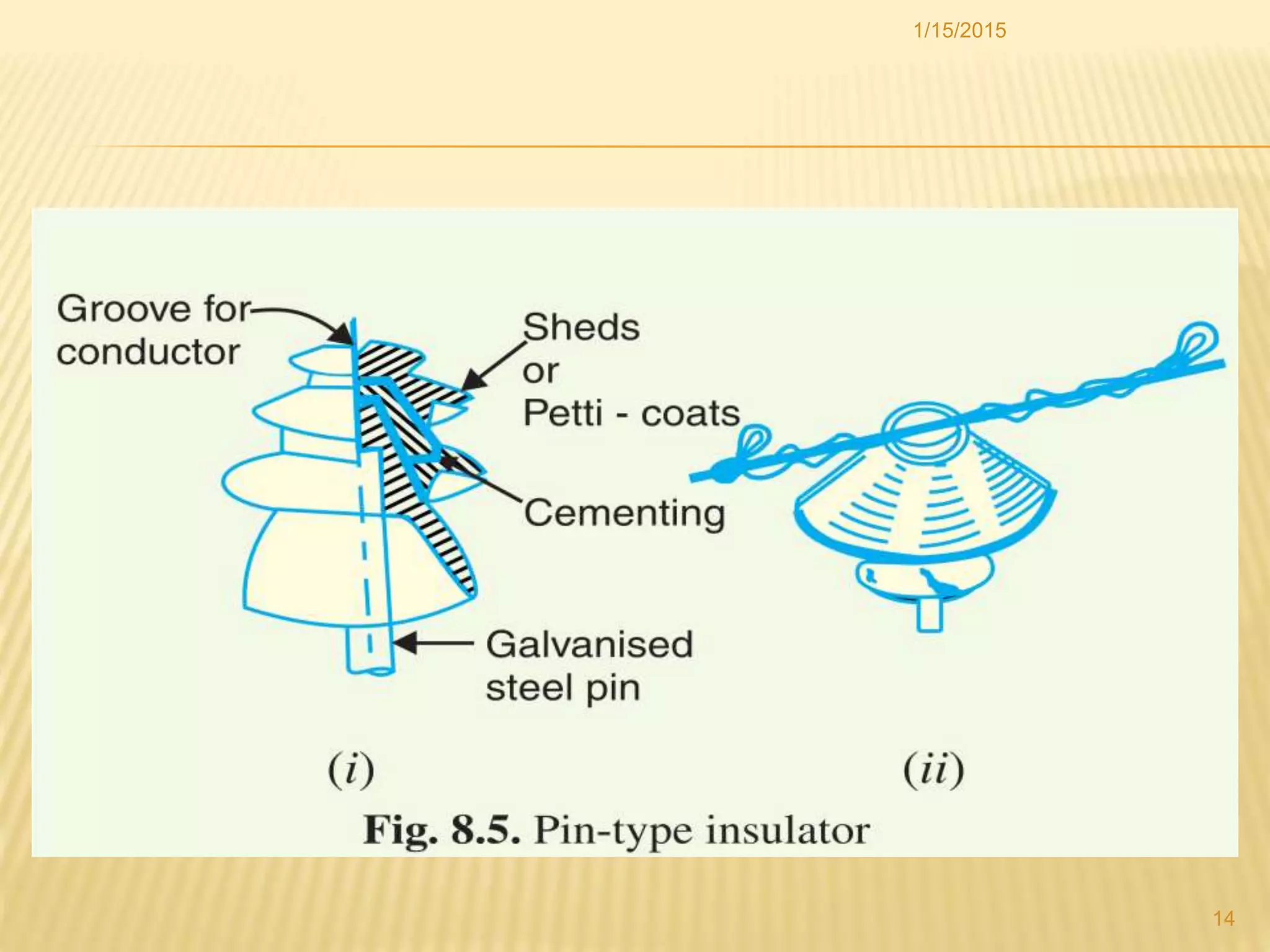
Importance of insulators in preventing leakage currents with desirable properties including mechanical strength, electrical resistance.
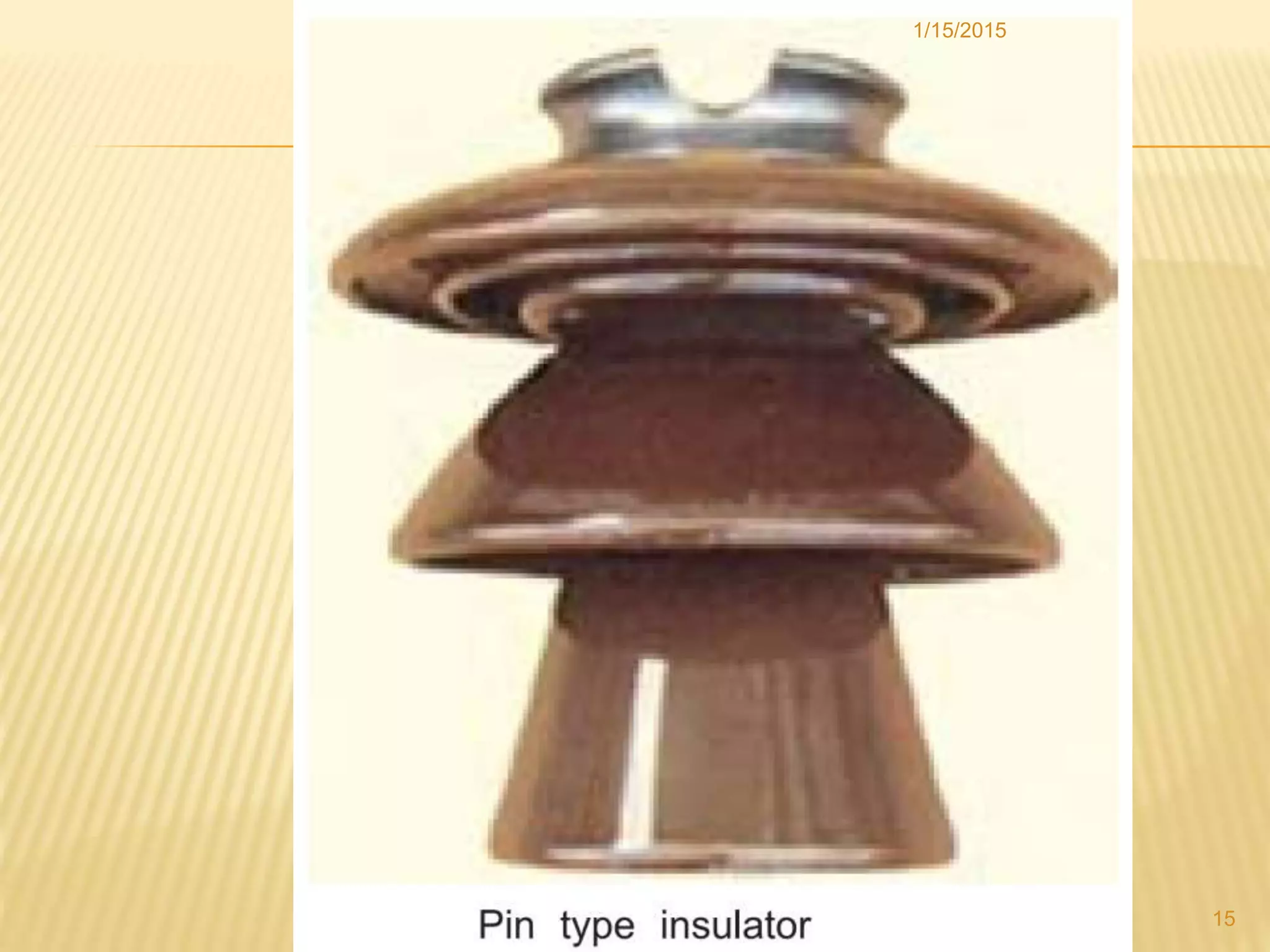
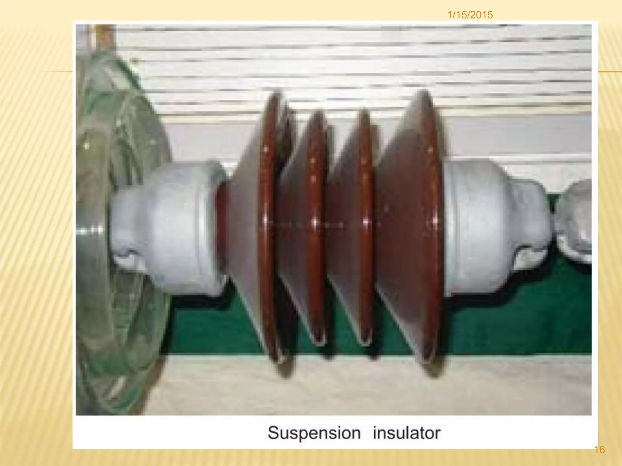
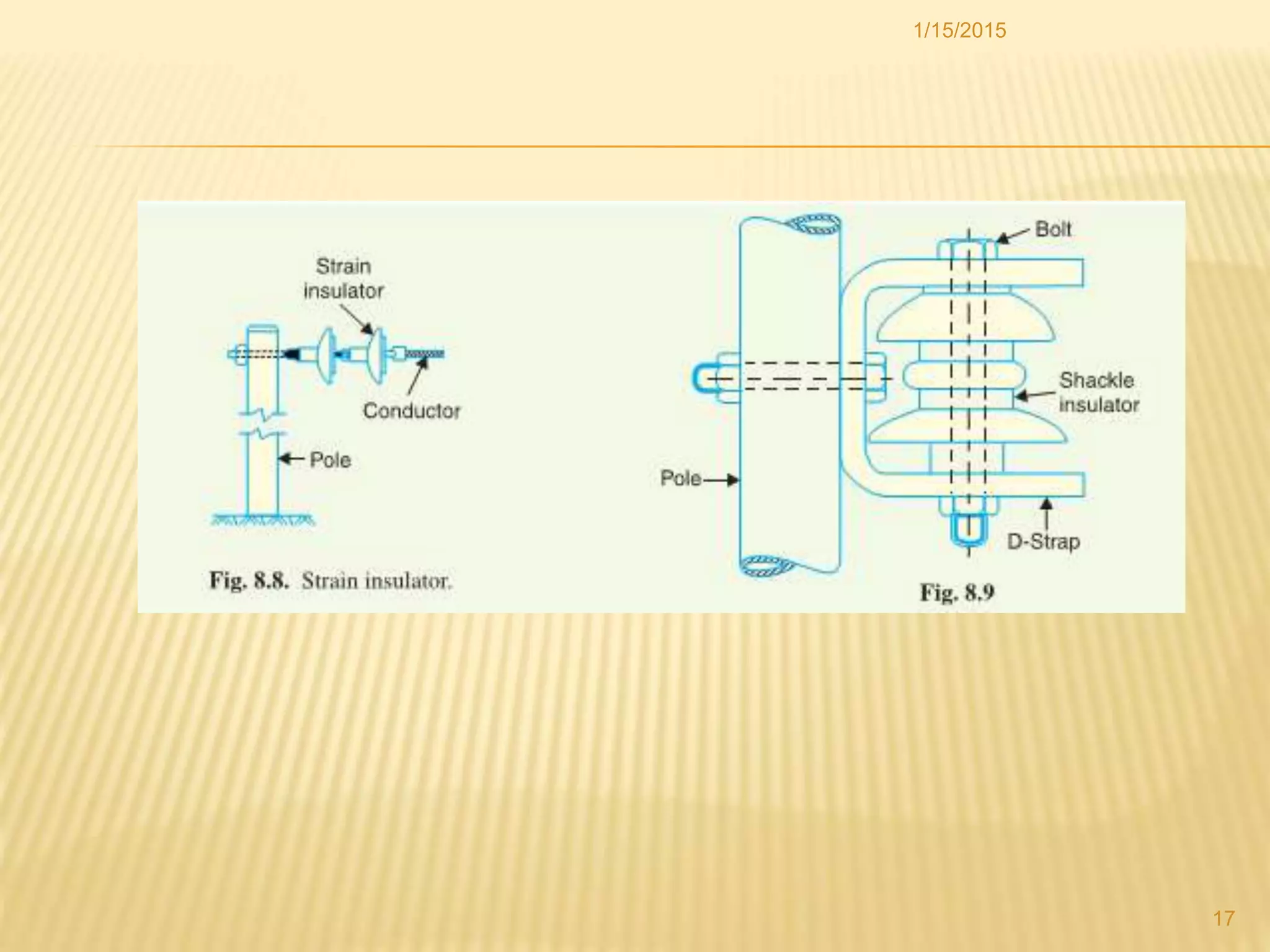
Varieties of insulators used in overhead lines: pin type, suspension type, strain and shackle insulators.
Explanation of corona effect at high voltages, its visual characteristics, sound, and power loss due to ionization.
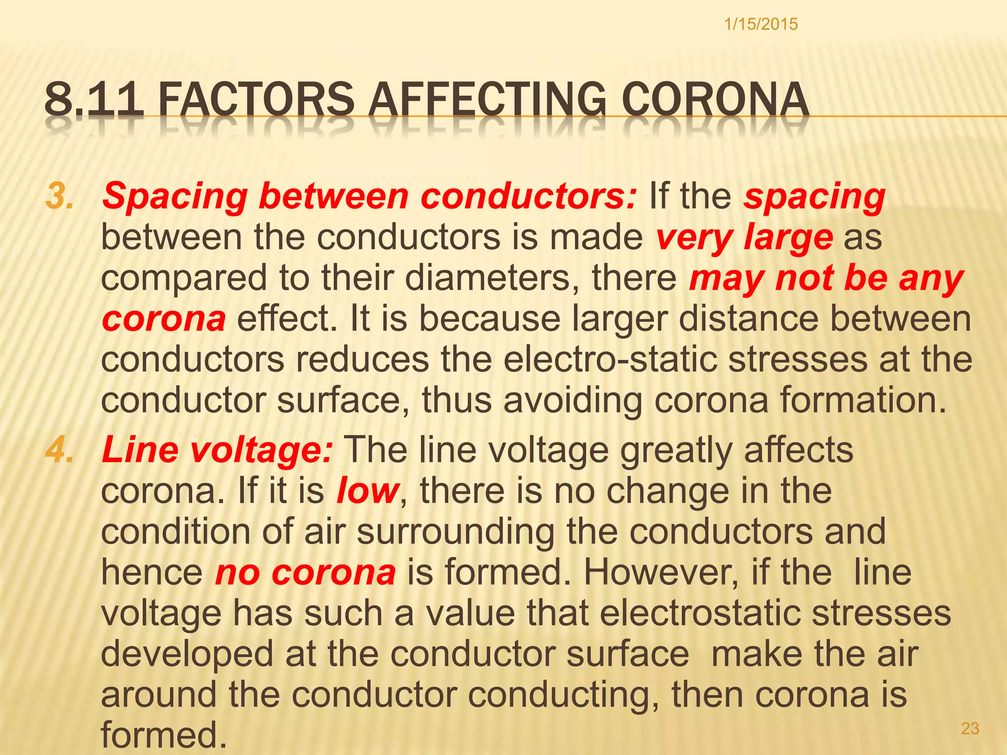
External factors influencing corona effect: atmospheric conditions, conductor shape, spacing between conductors, and line voltage.
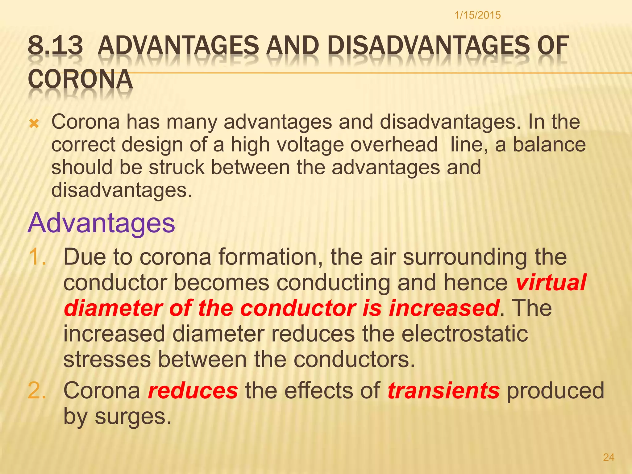
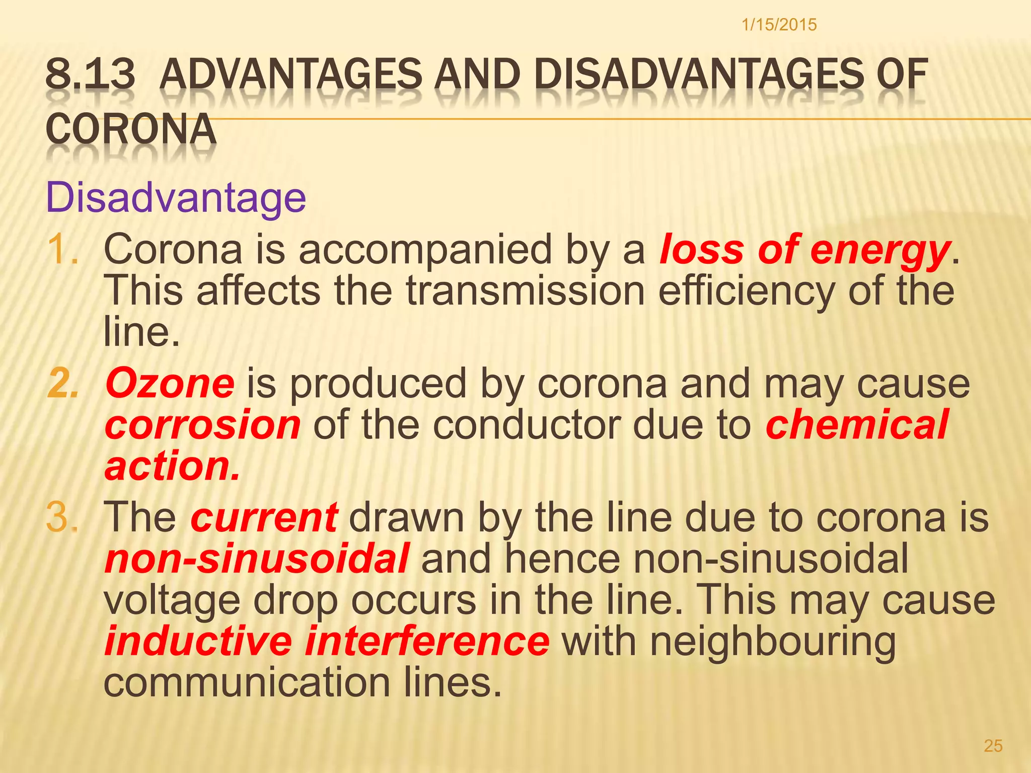
Balance of corona benefits like reduced electrostatic stress against disadvantages such as energy loss and inductive interference.
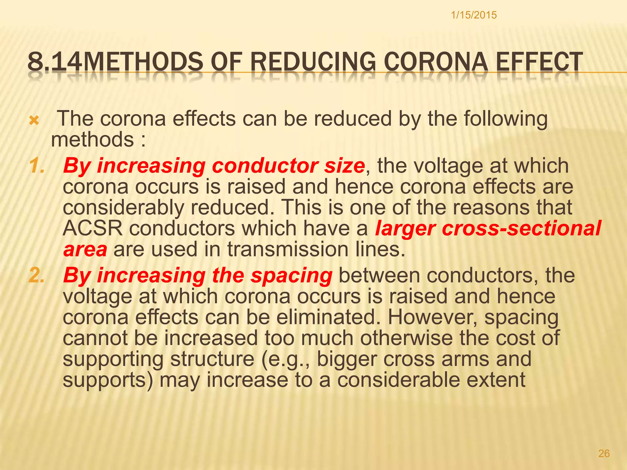
Strategies to mitigate corona effects through increasing conductor size and spacing to raise voltage thresholds.


![EXTRA HIGH VOLTAGE AC TRANSMISSION LINE [anjan mandal] (2).pdf](https://cdn.slidesharecdn.com/ss_thumbnails/extrahighvoltageactransmissionlineanjanmandal2-250421090522-e7a2661f-thumbnail.jpg?width=640&height=640&fit=bounds)


