Downloaded 785 times


Here are the steps to solve this problem: a) Cutting speed (V) - Maximum cutting speed (at outer diameter D0): Vmax = πD0N = π × 12 × 400 = 15072 mm/min - Minimum cutting speed (at inner diameter Df): Vmin = πDfN = π × 11 × 400 = 13816 mm/min b) Depth of cut (d) and cutting time (t) - Depth of cut (d) = (D0 - Df)/2 = (12 - 11)/2 = 0.5 mm - Feed rate (f) = Axial speed (
Overview of manufacturing processes including recommended textbooks and reference materials.
Introduction to various manufacturing processes, including chip less, material removal, and forming operations.
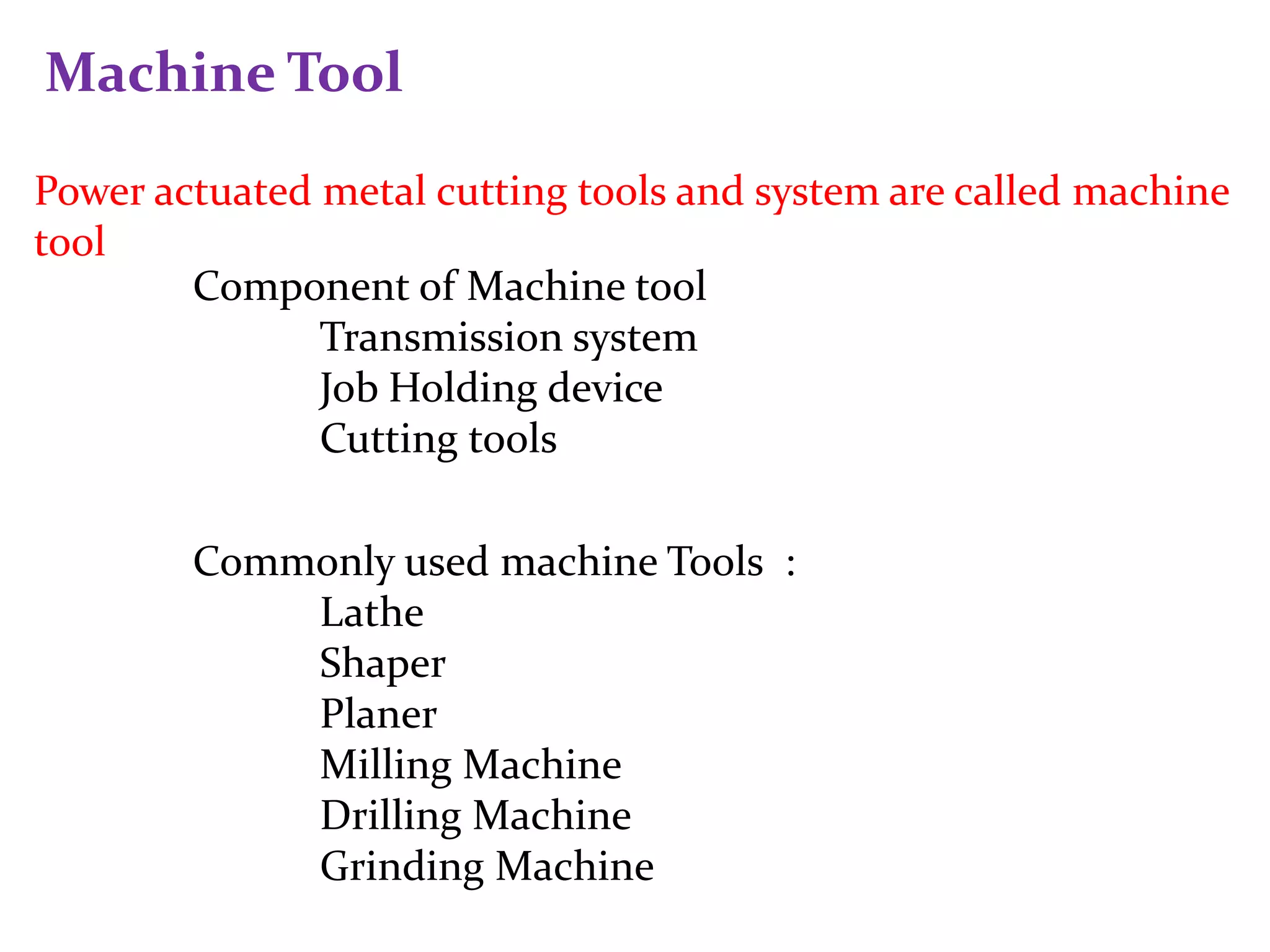
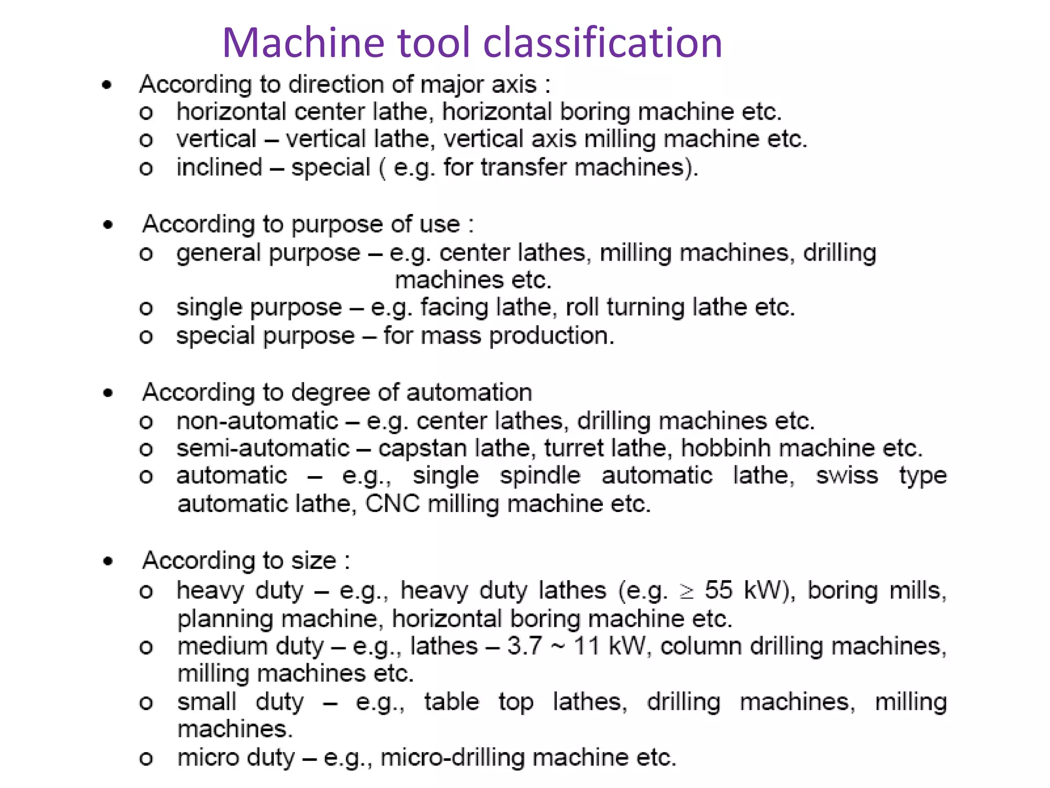
Definition of machine tools, components, and classification of various machine tools used in metal cutting.
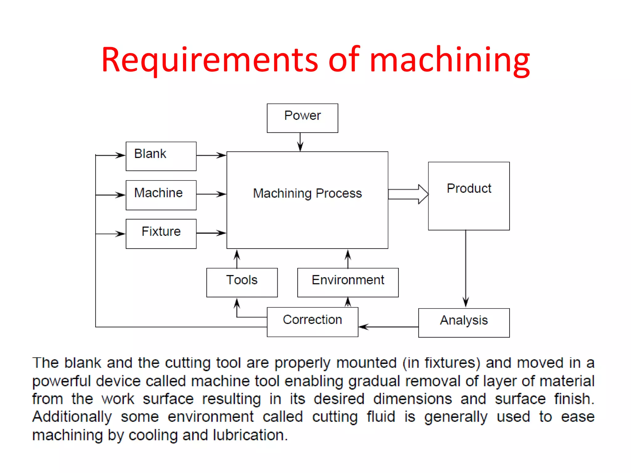
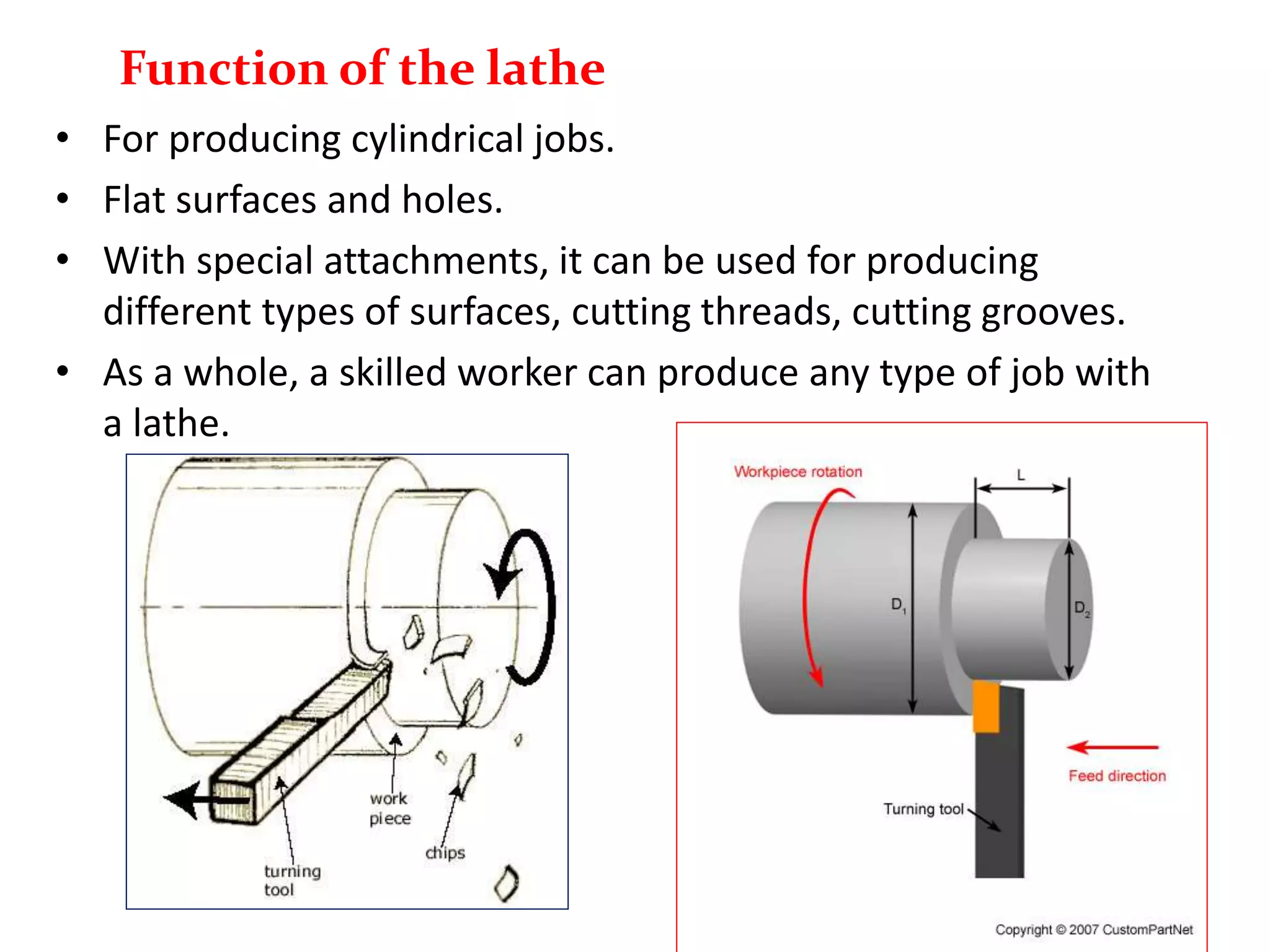
Explanation of machining, focusing on requirements and functionalities of lathes for producing jobs.
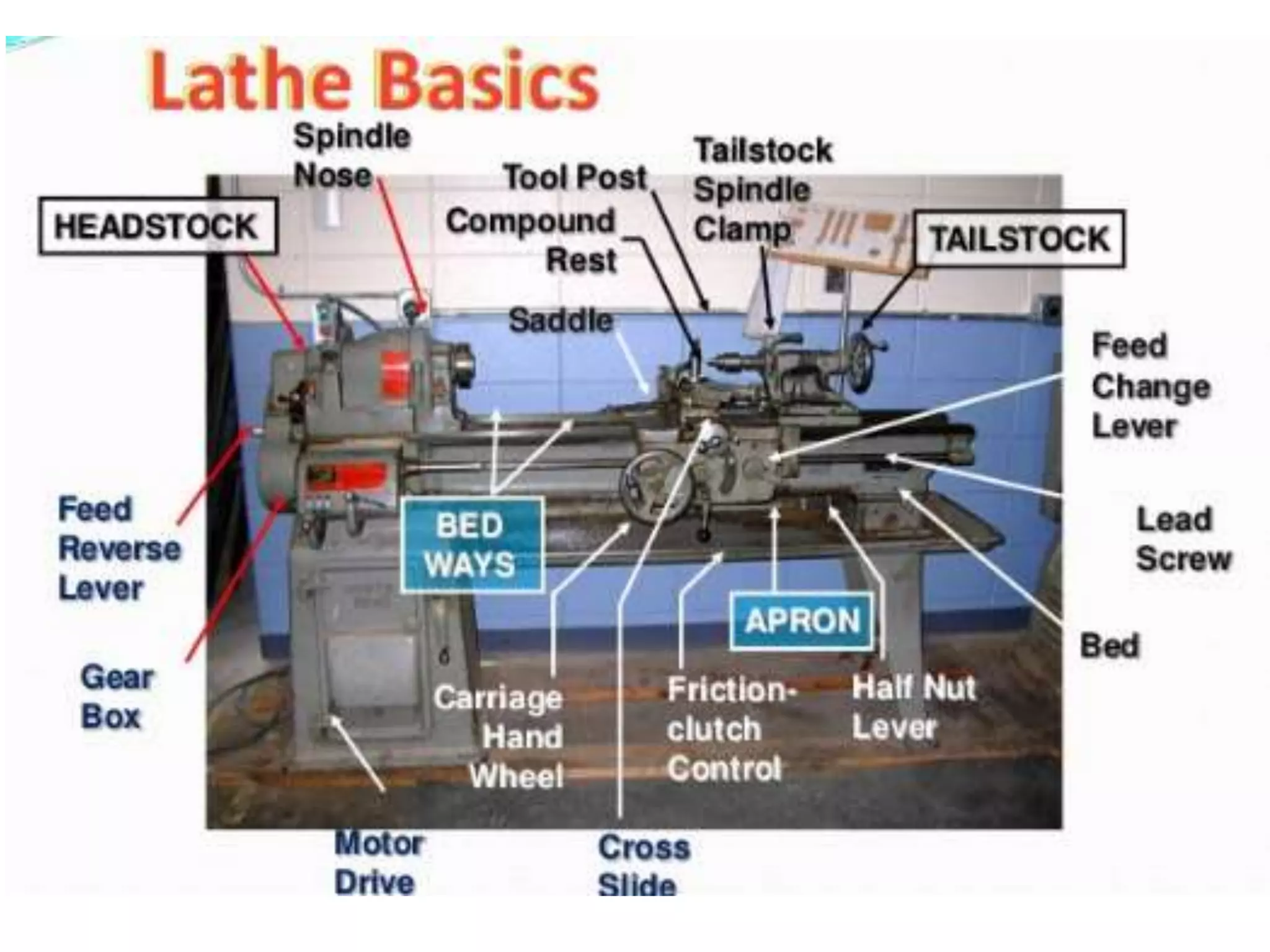
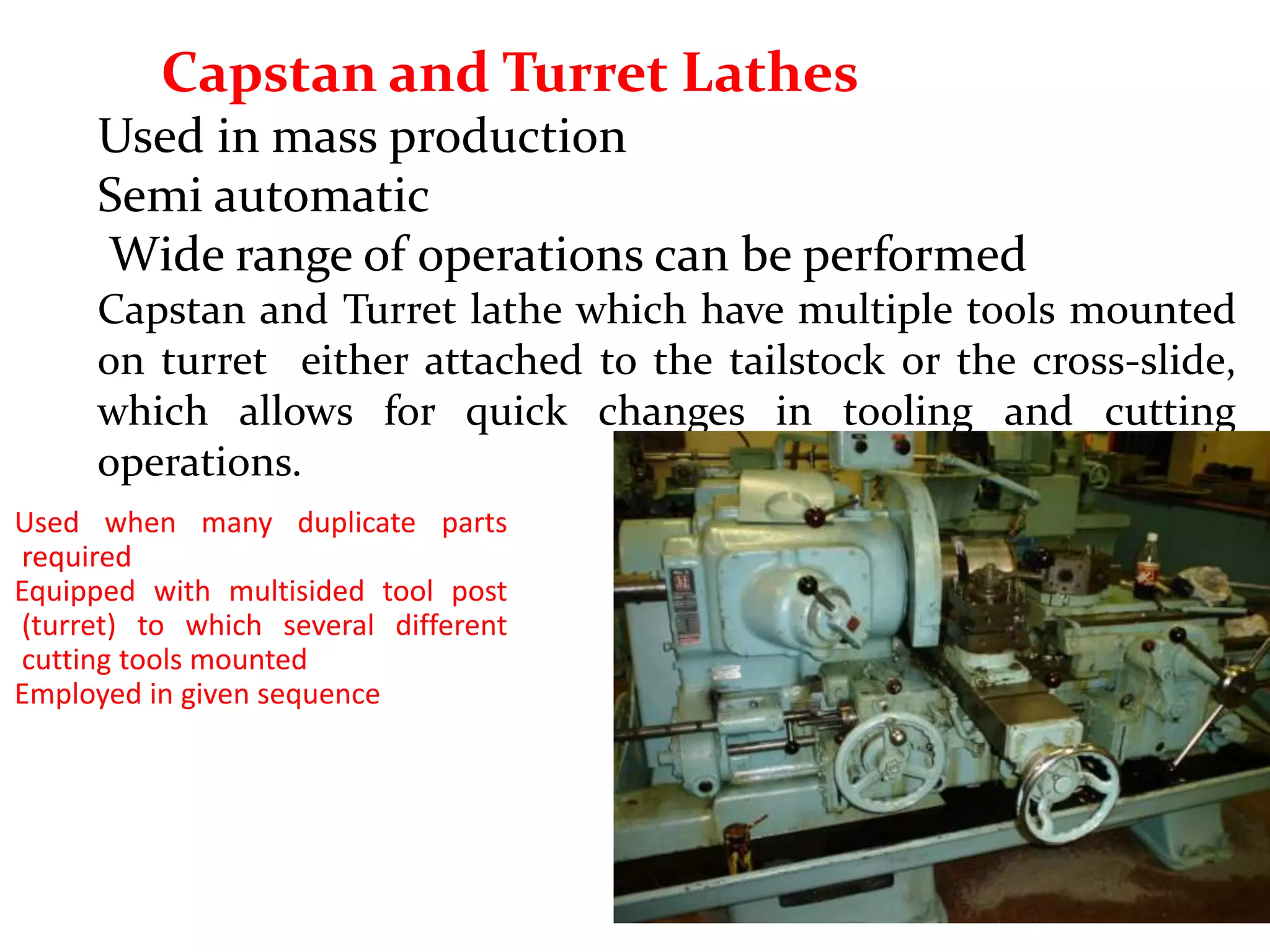
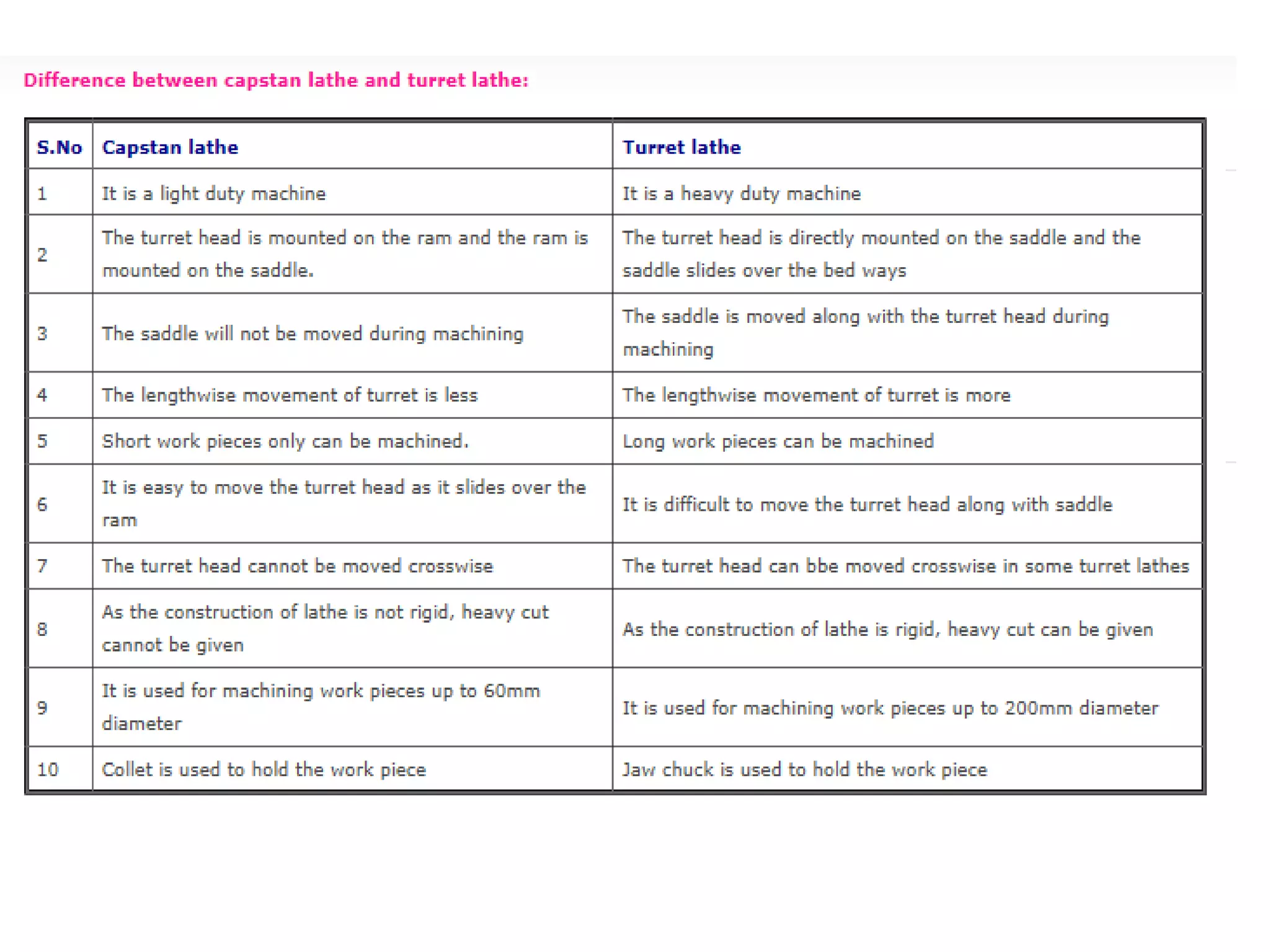
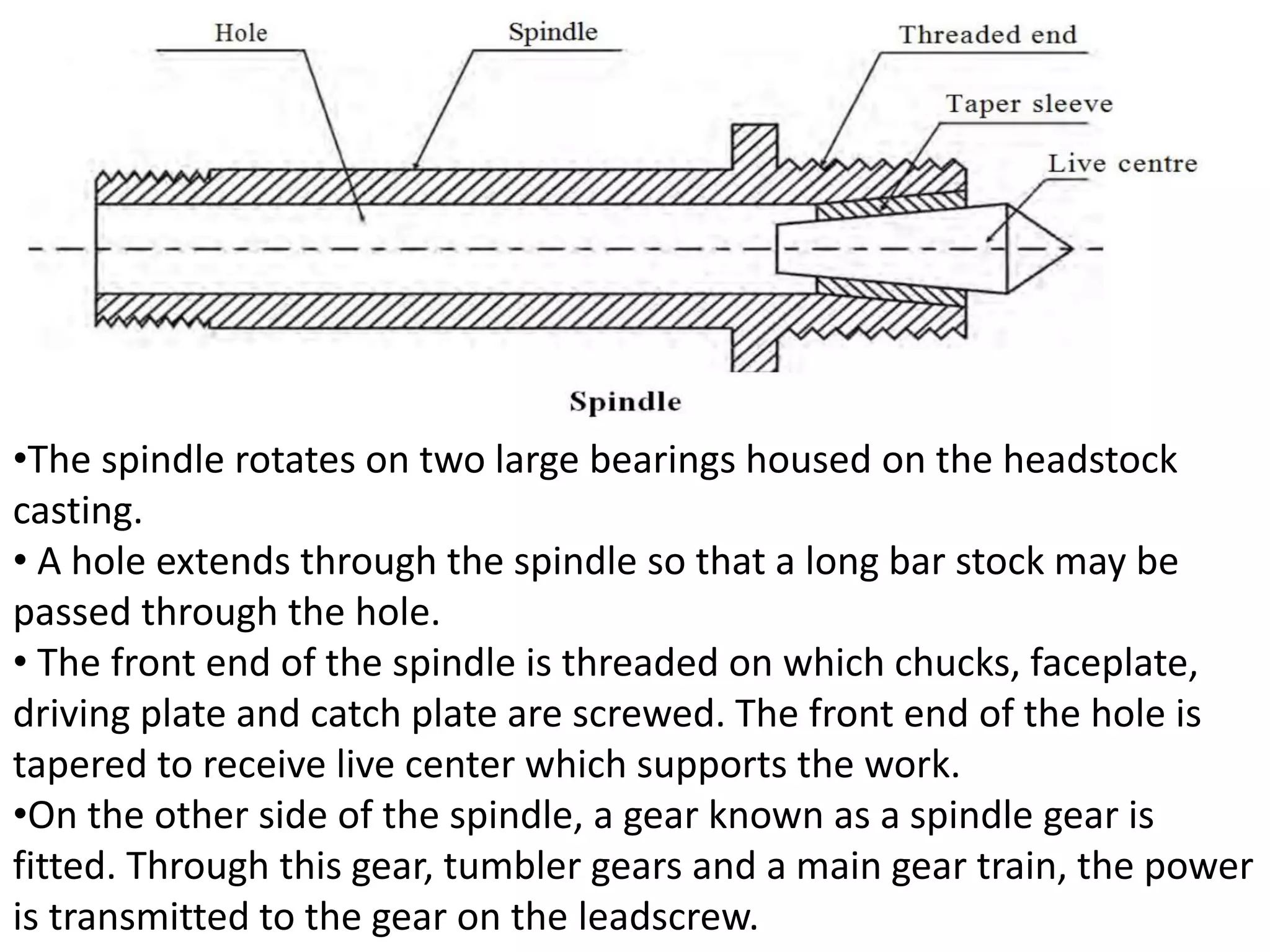
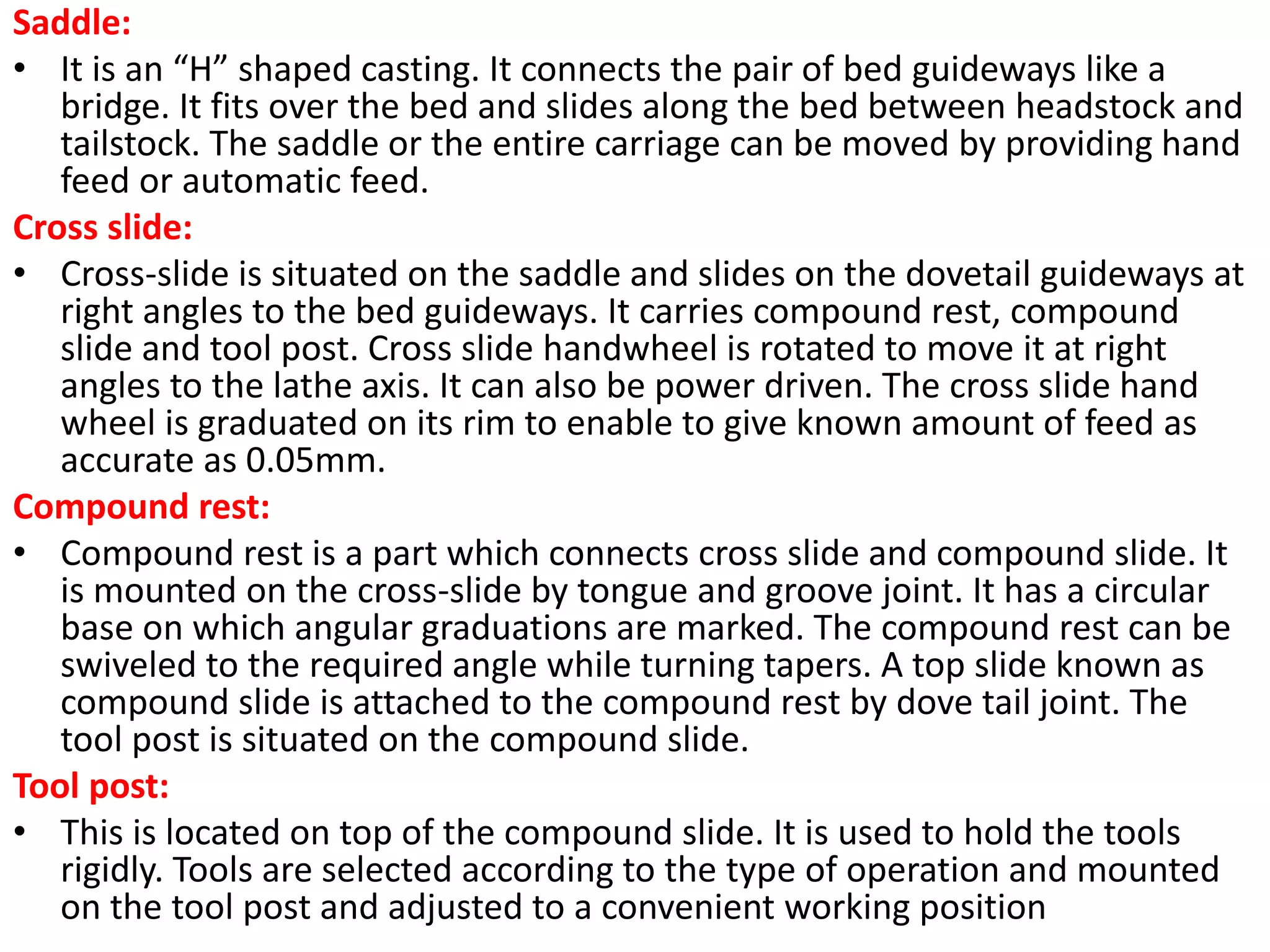
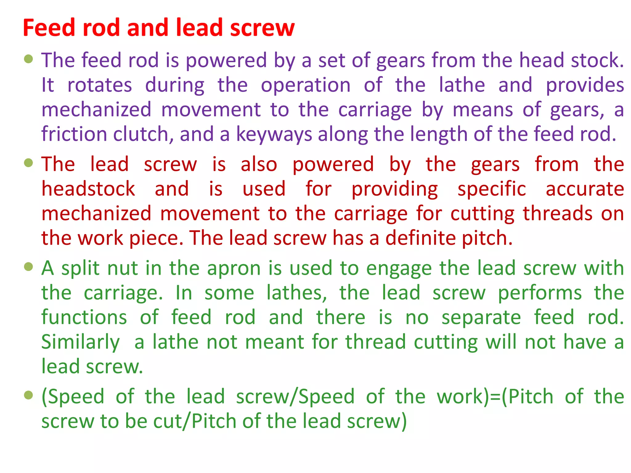
Detailed discussion of lathe components including bed, carriage, and common types of lathes.
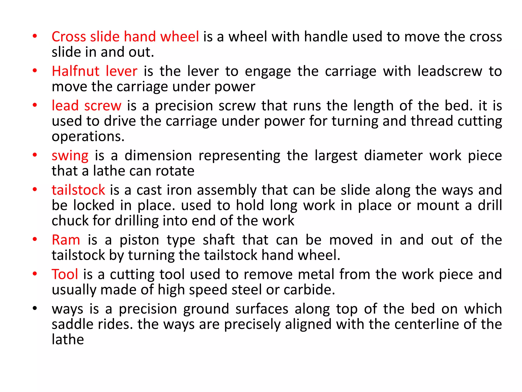
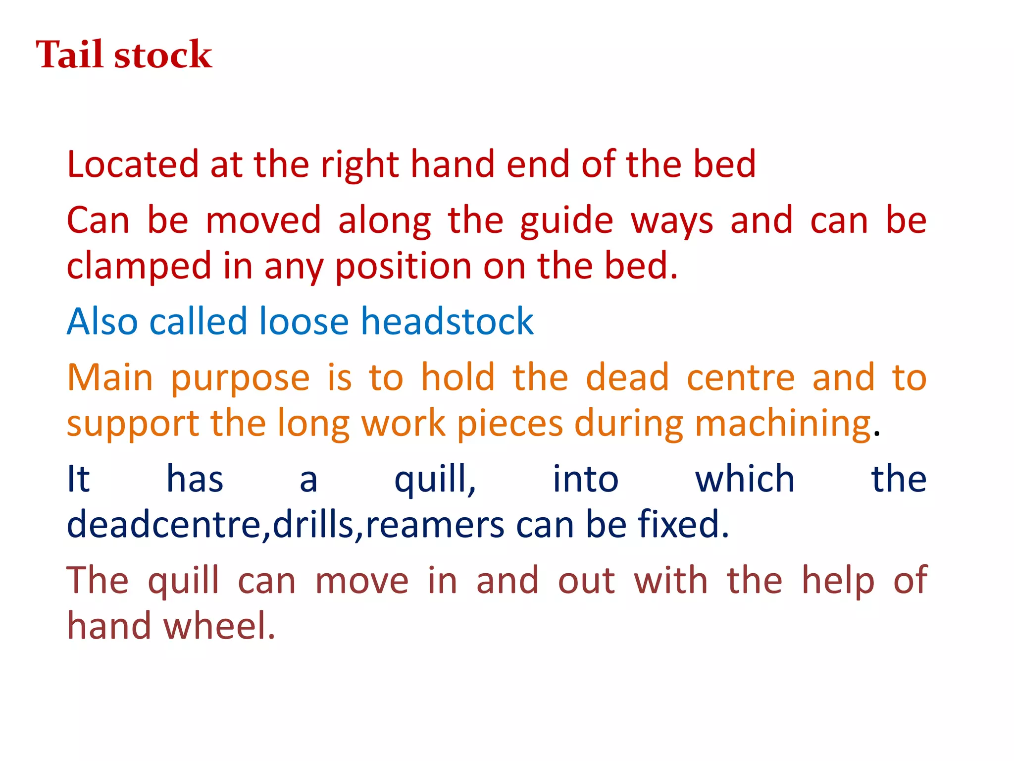
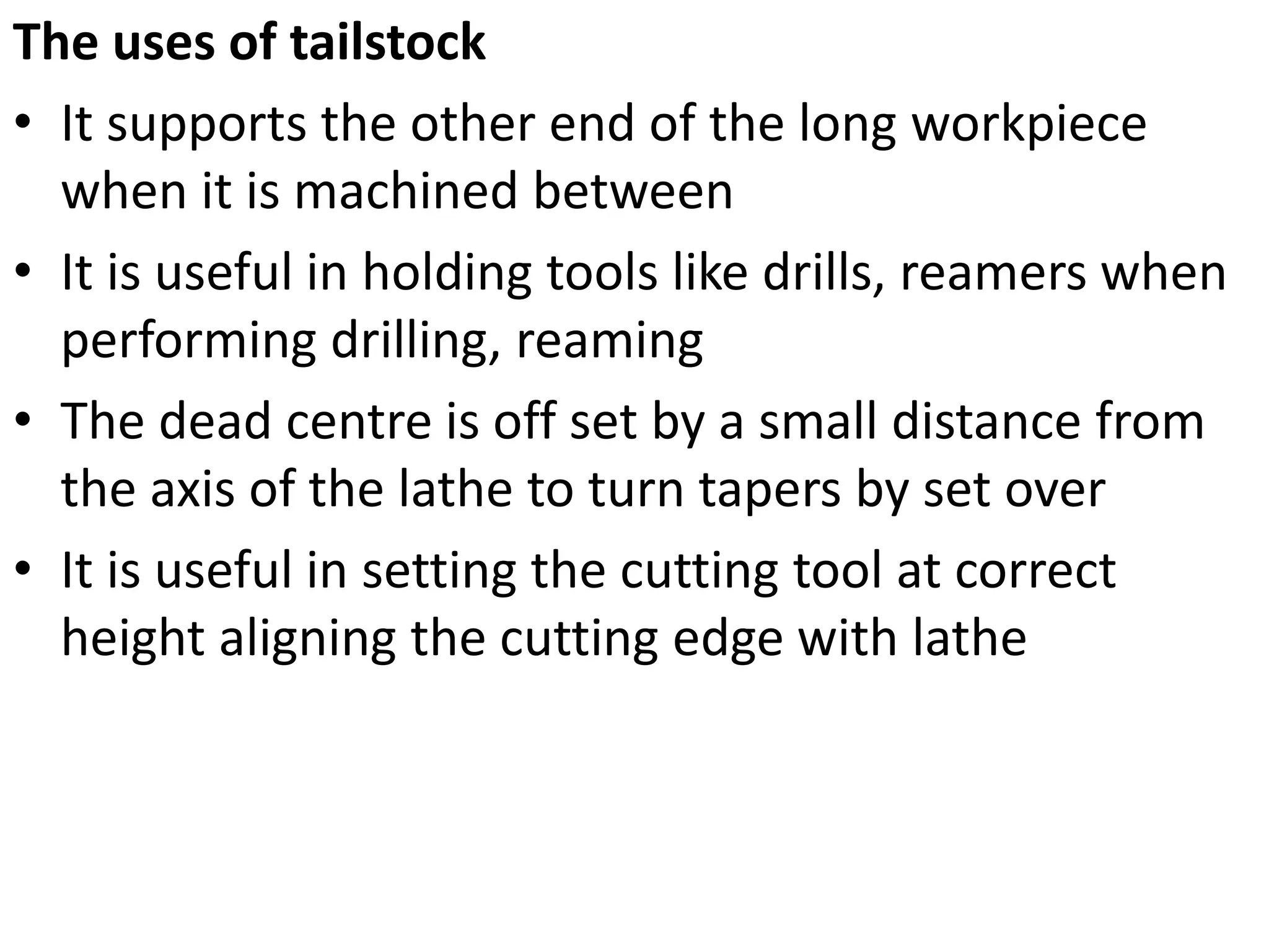
Explanation of lathe operations, parts like tailstock and carriage, and their specific functionalities.
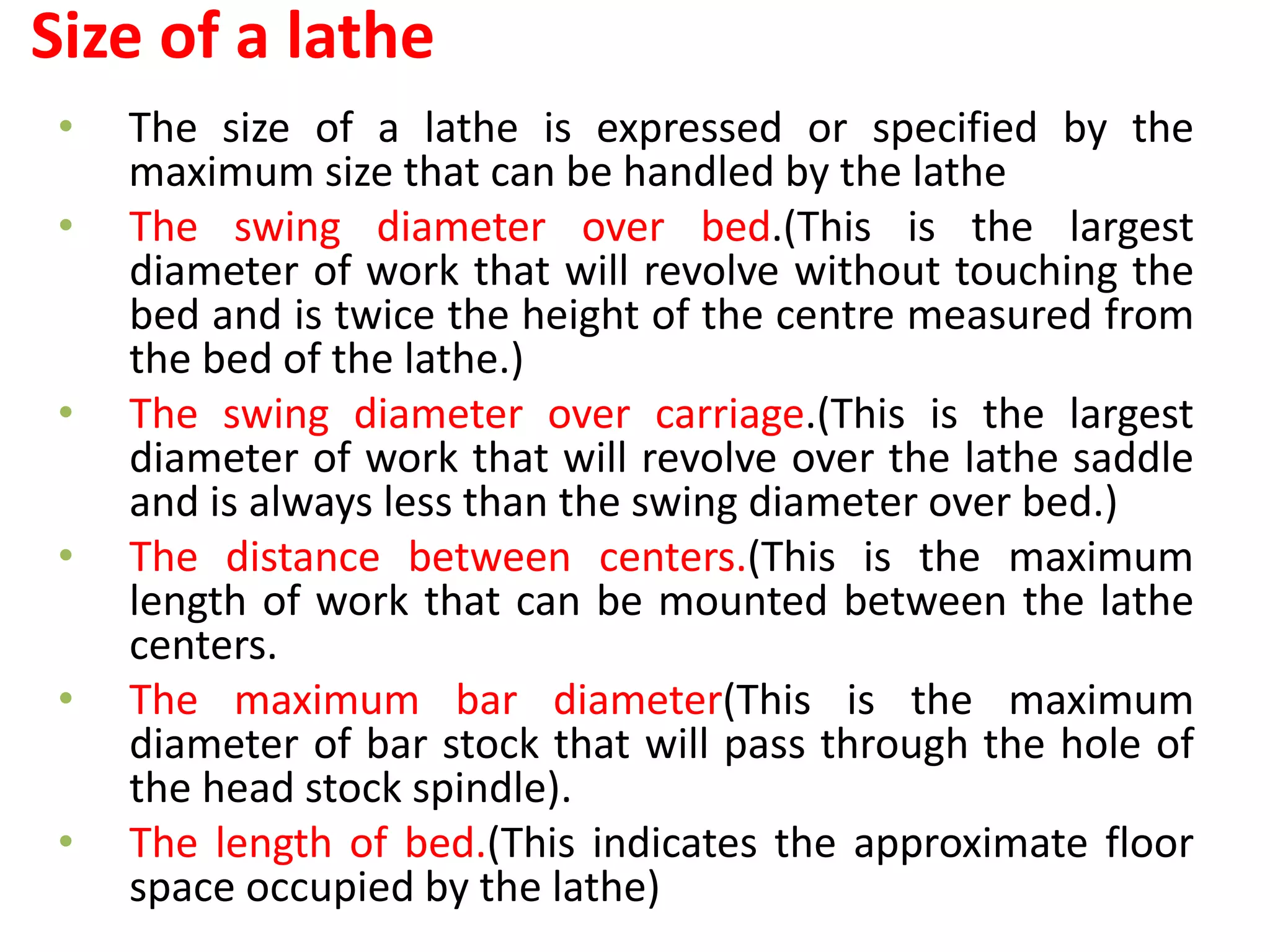
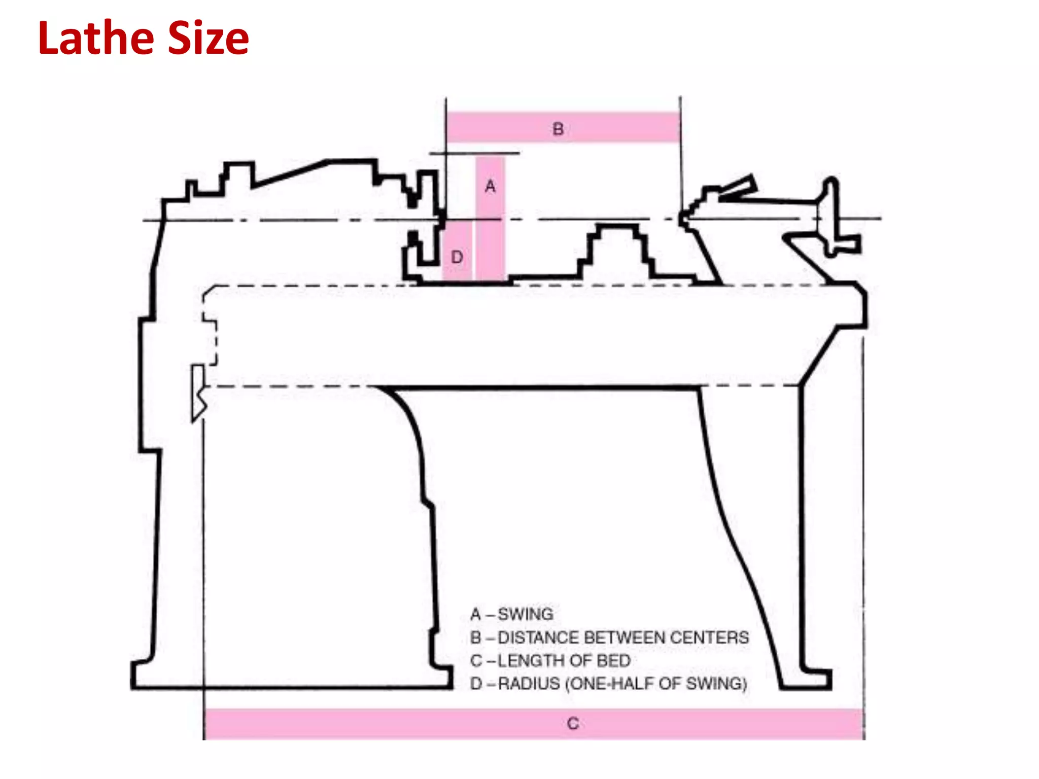
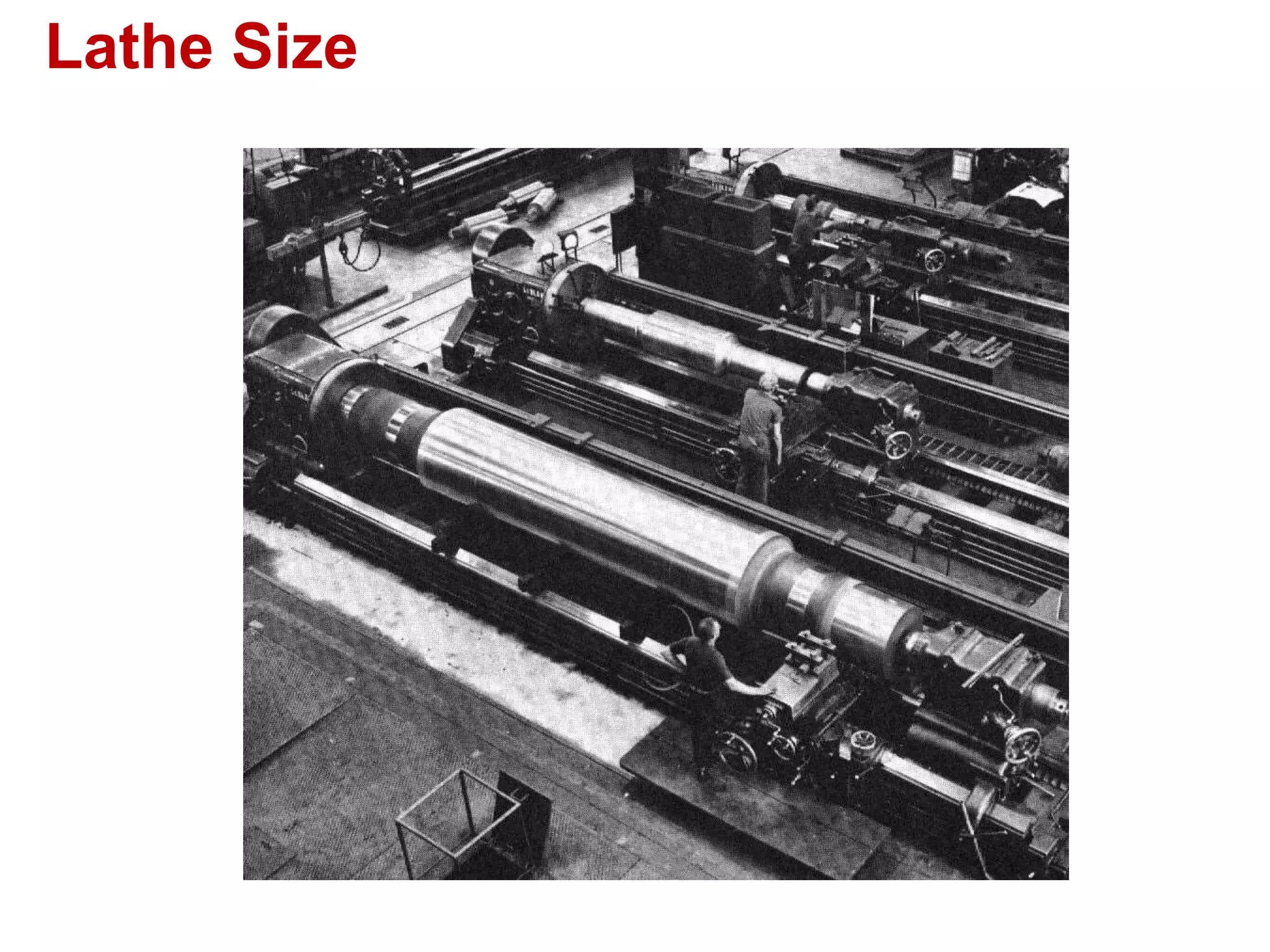
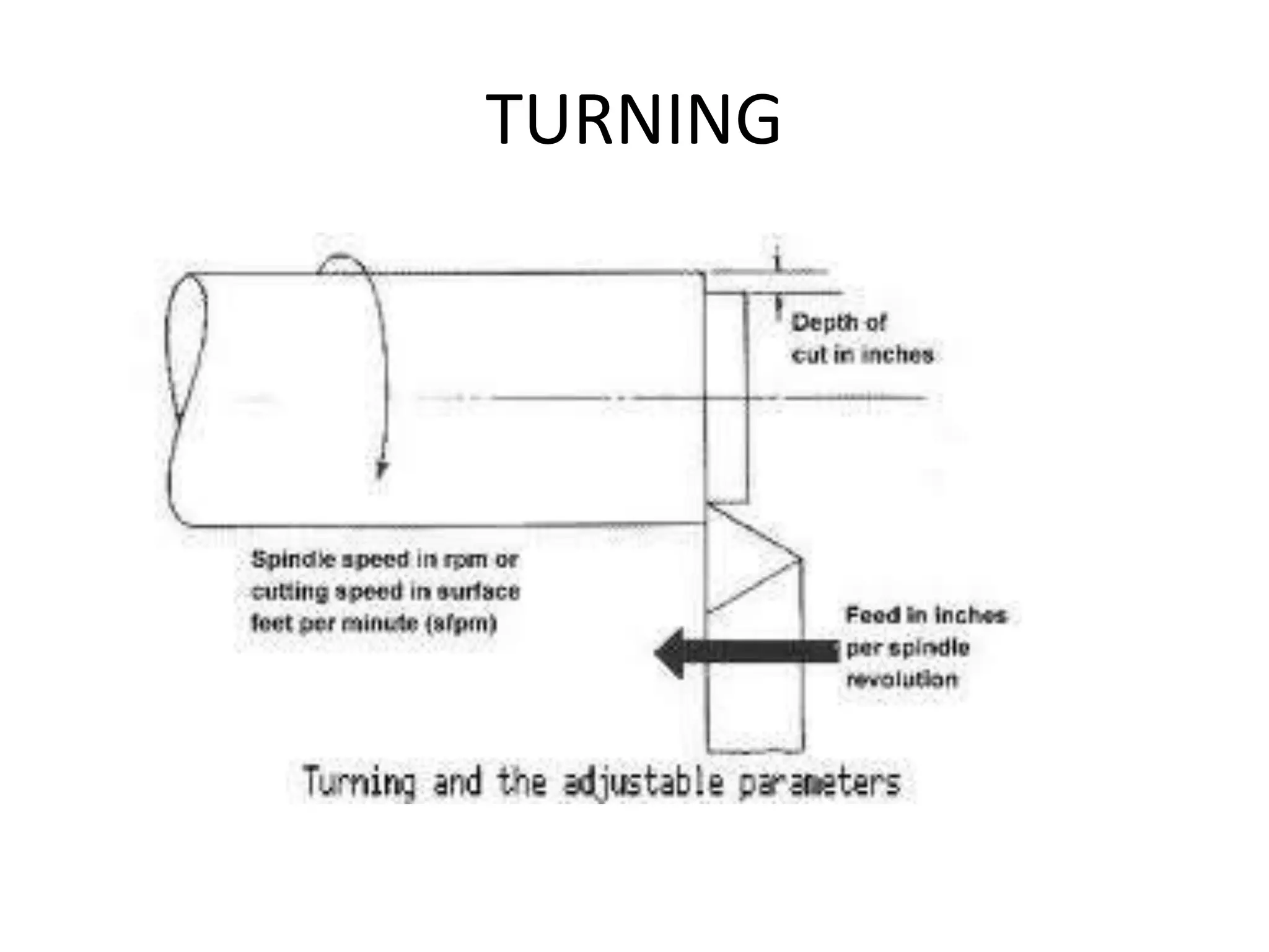
Specifications for lathe sizes related to swing diameter, length between centers, and maximum bar diameters.Key operating conditions including cutting speed, depth of cut, and feed affecting machining time.
Methods for calculating machining time based on machining parameters and operational settings.
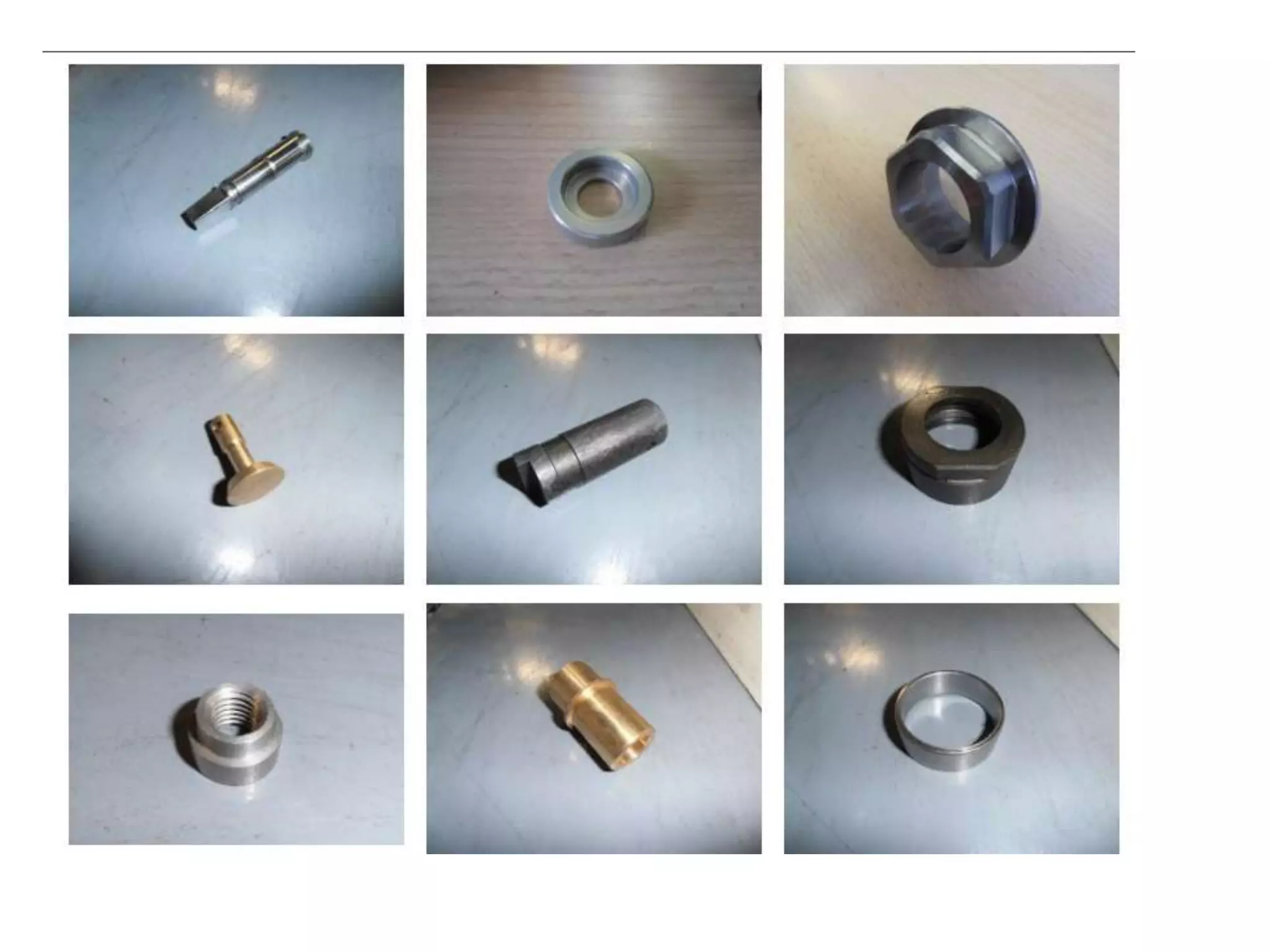
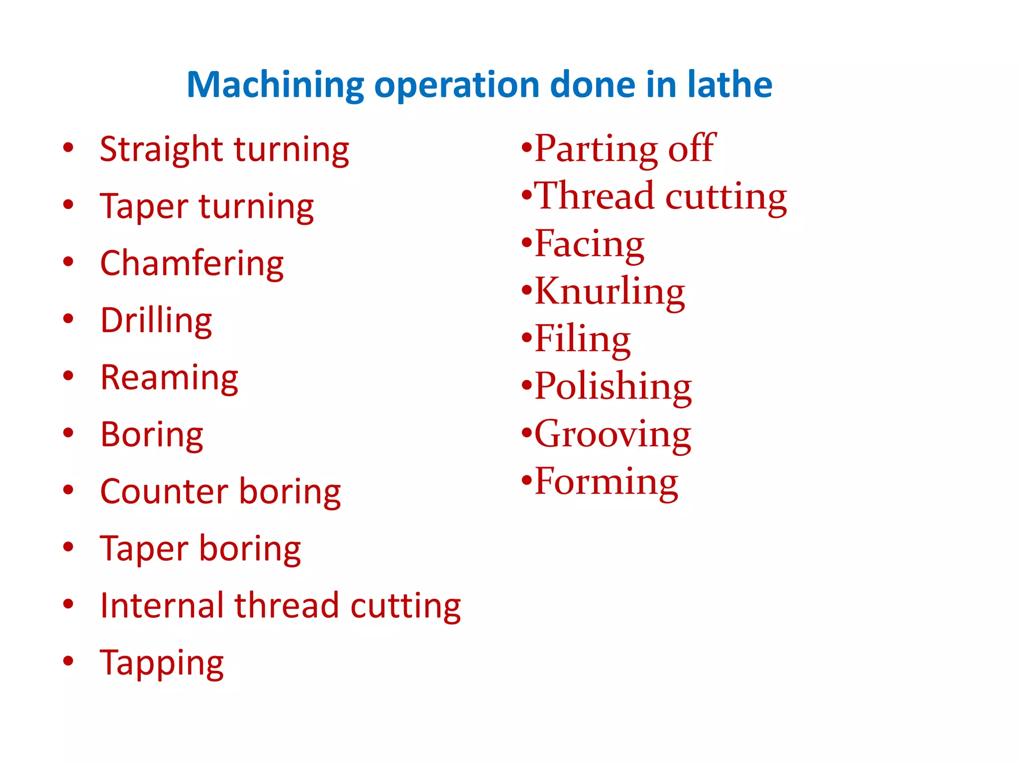
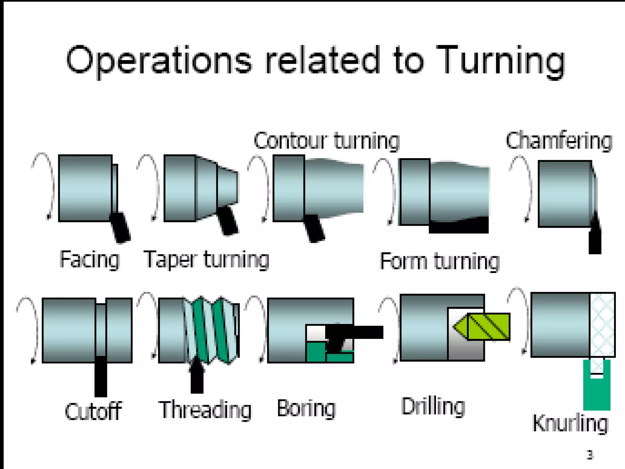
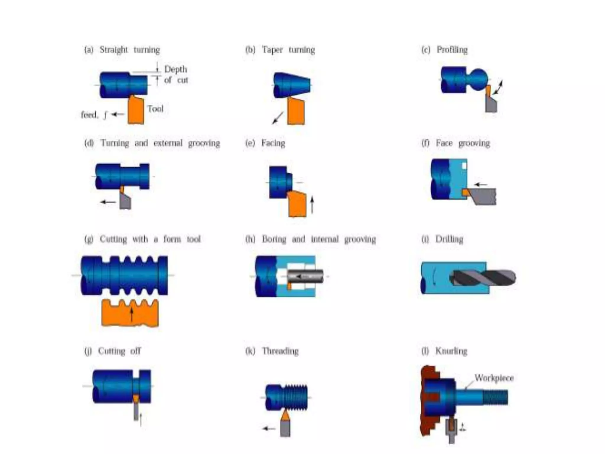
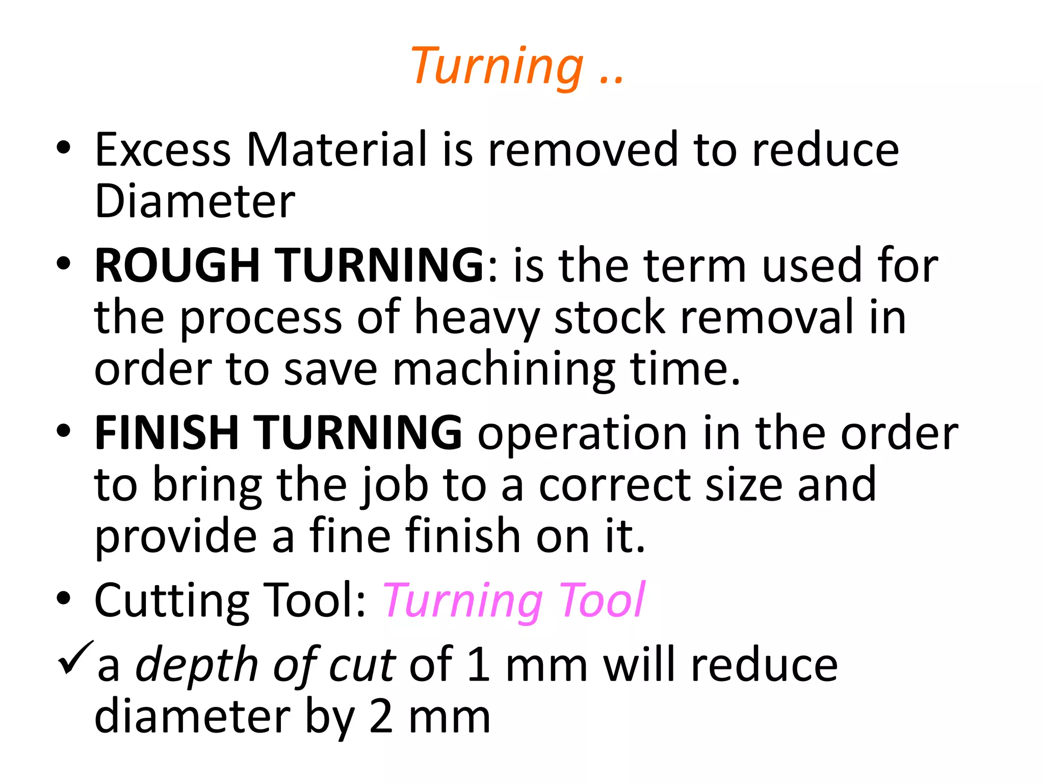
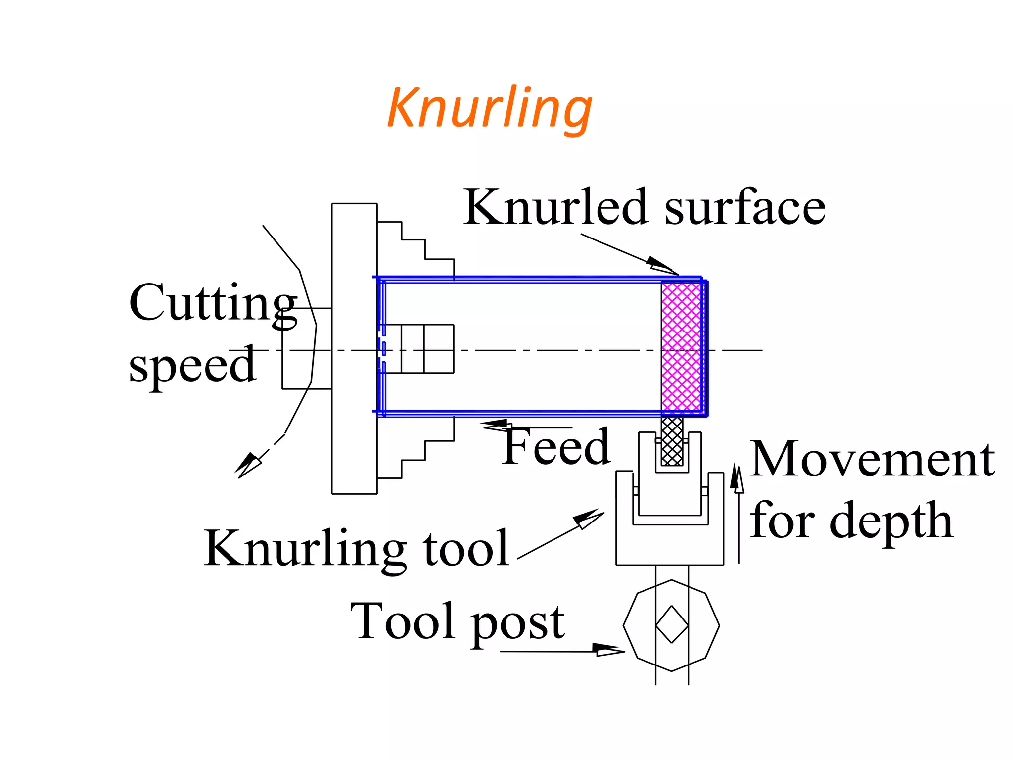
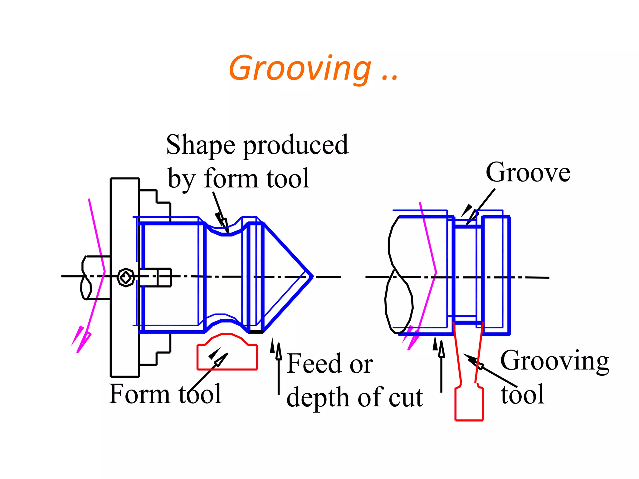
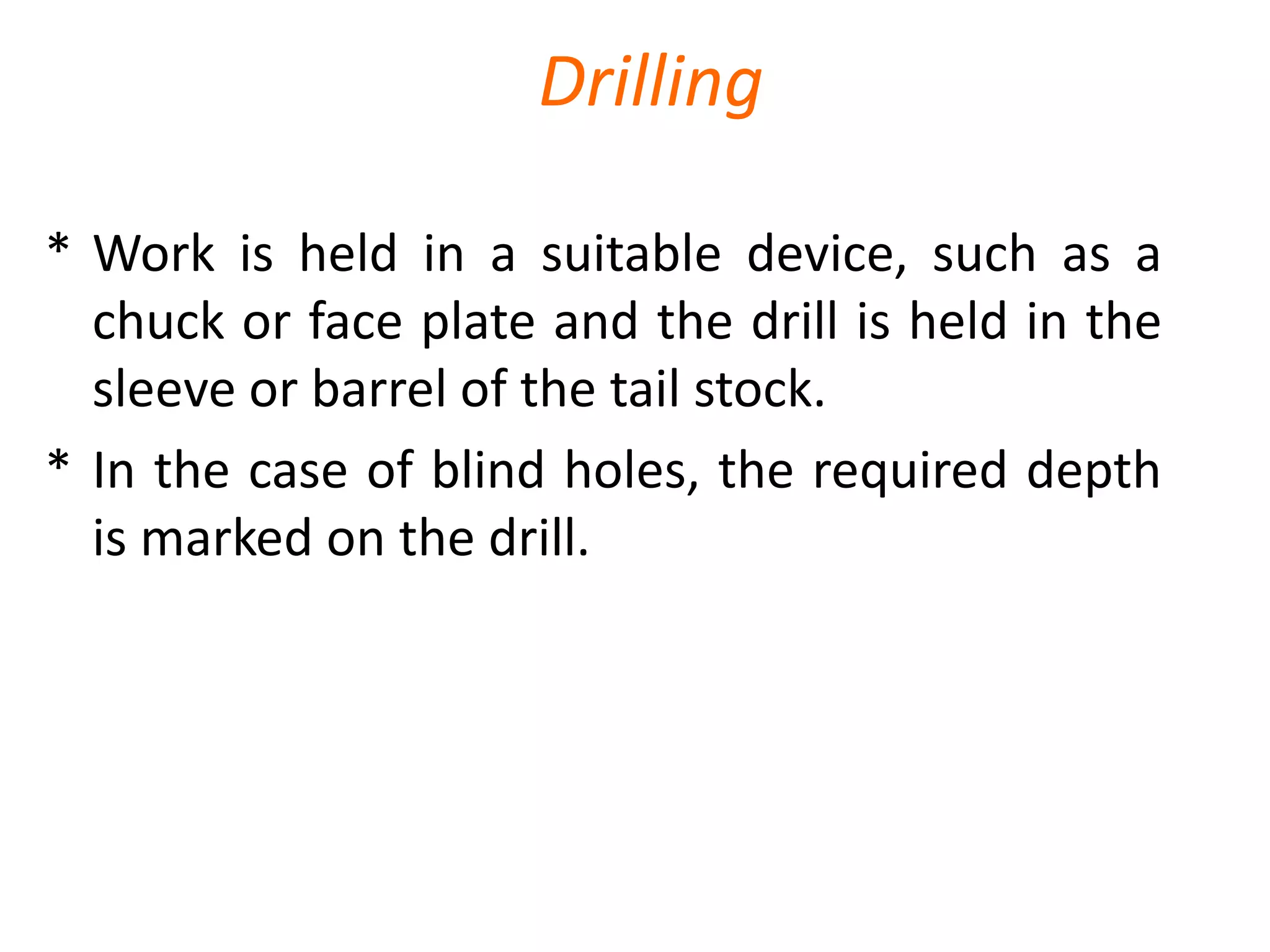
Overview of various machining operations such as turning, drilling, and grooving pertinent to lathe usage.
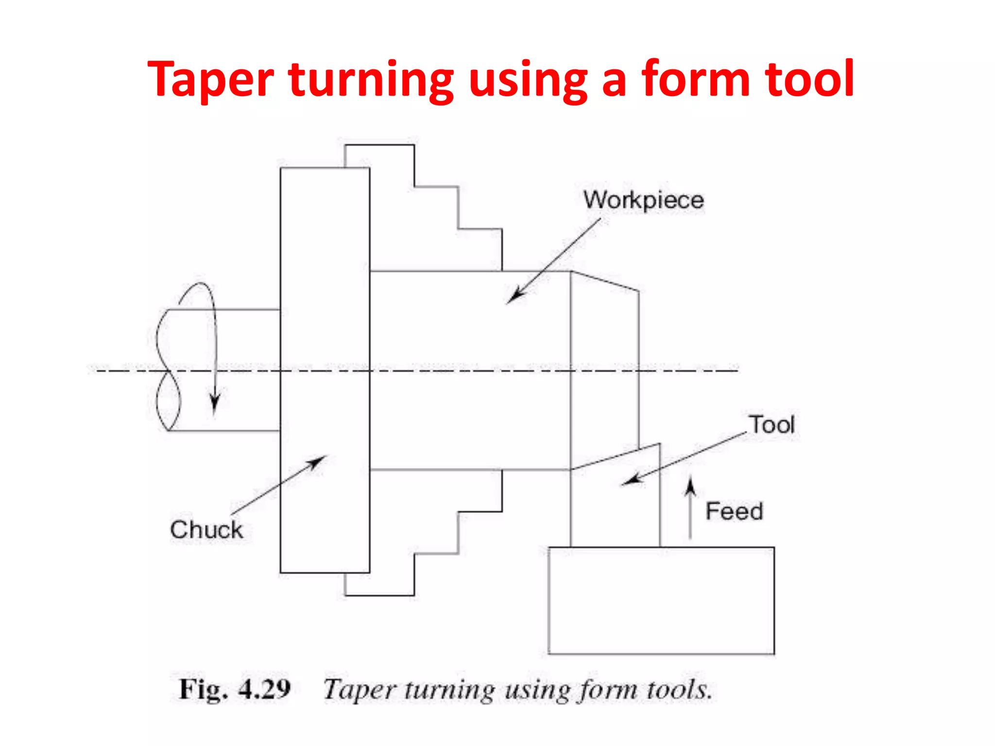
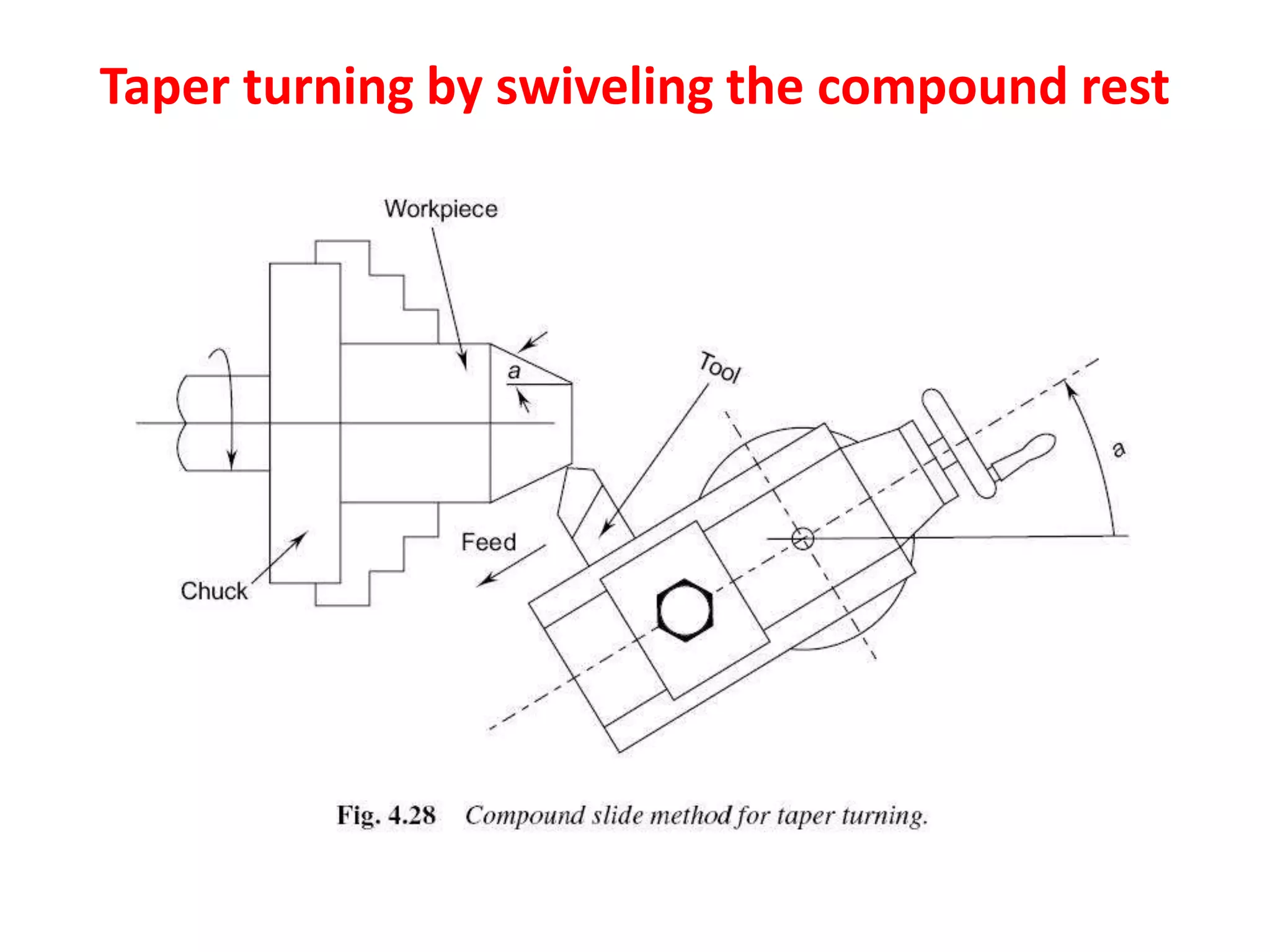
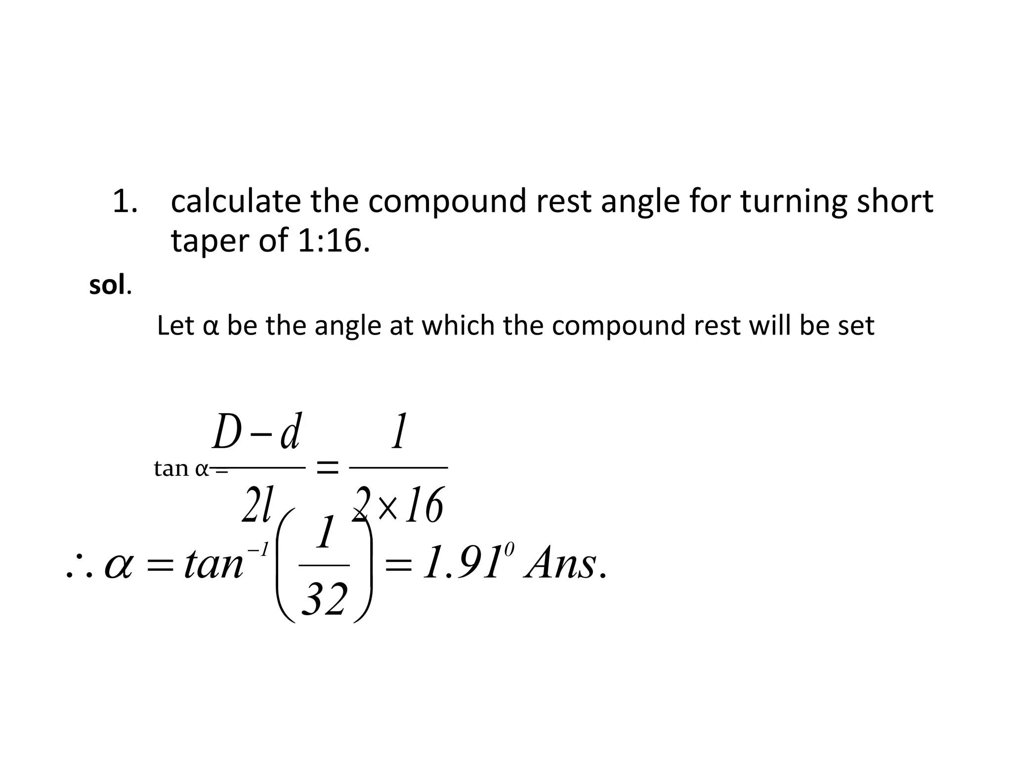
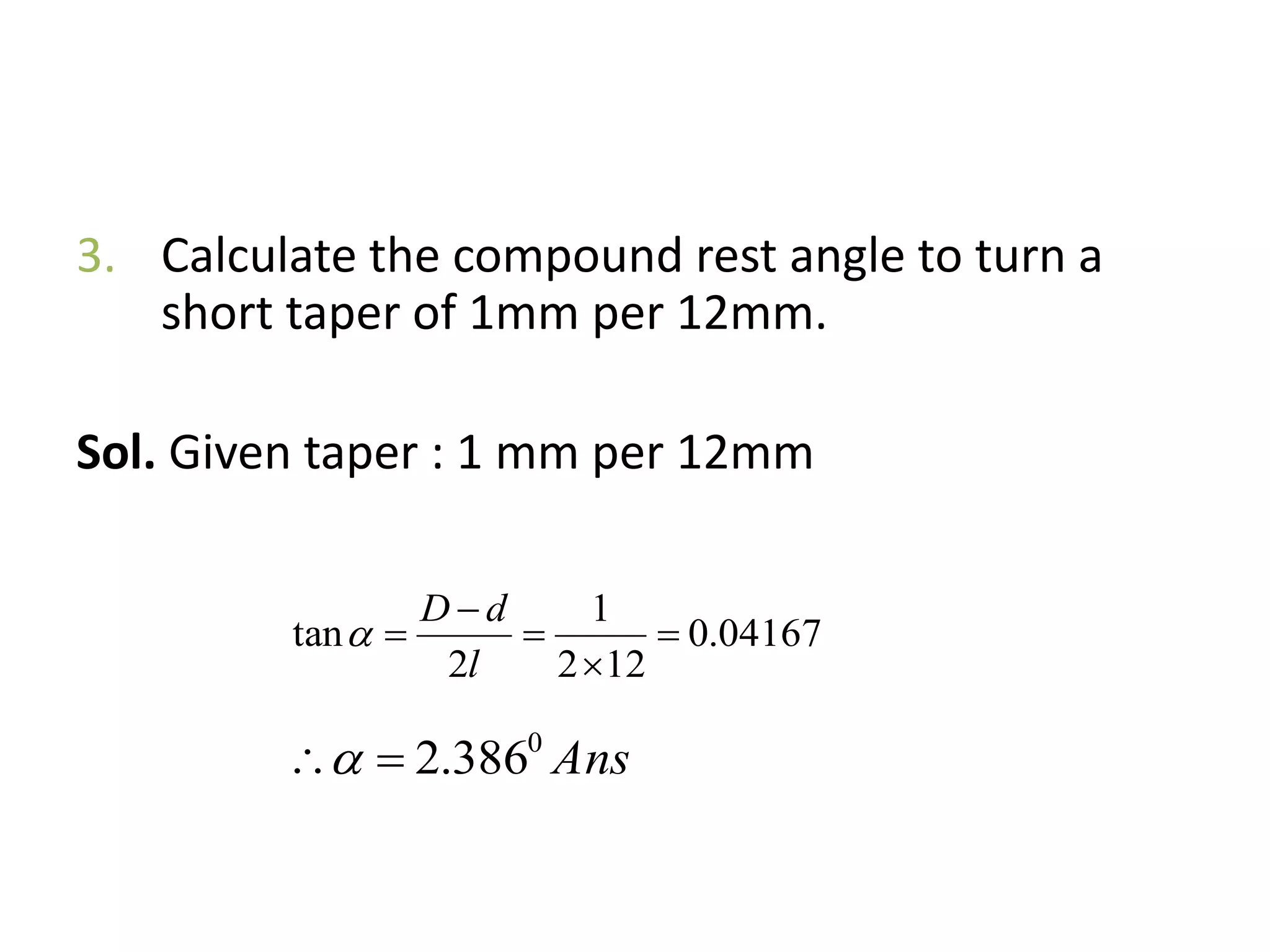
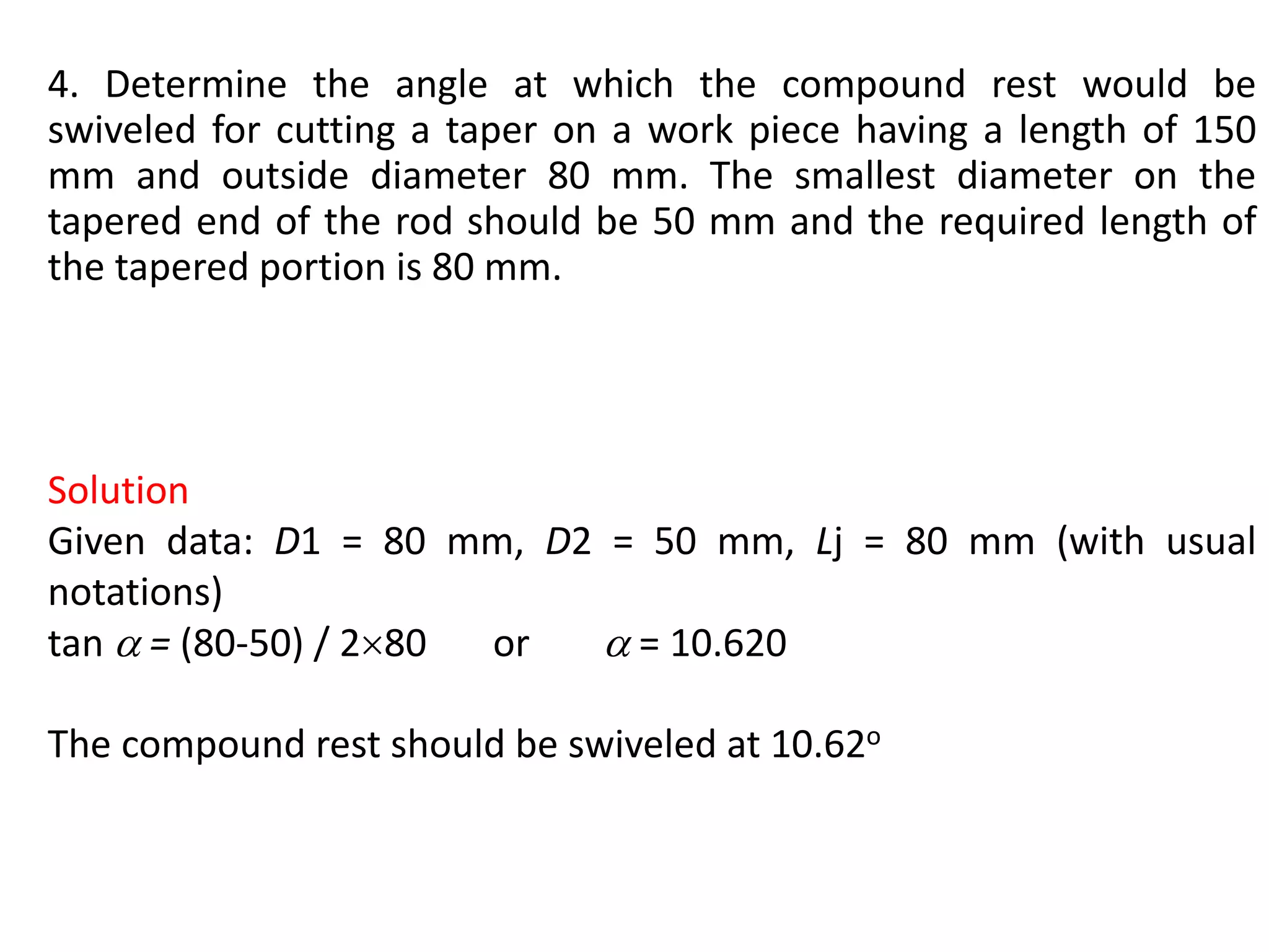
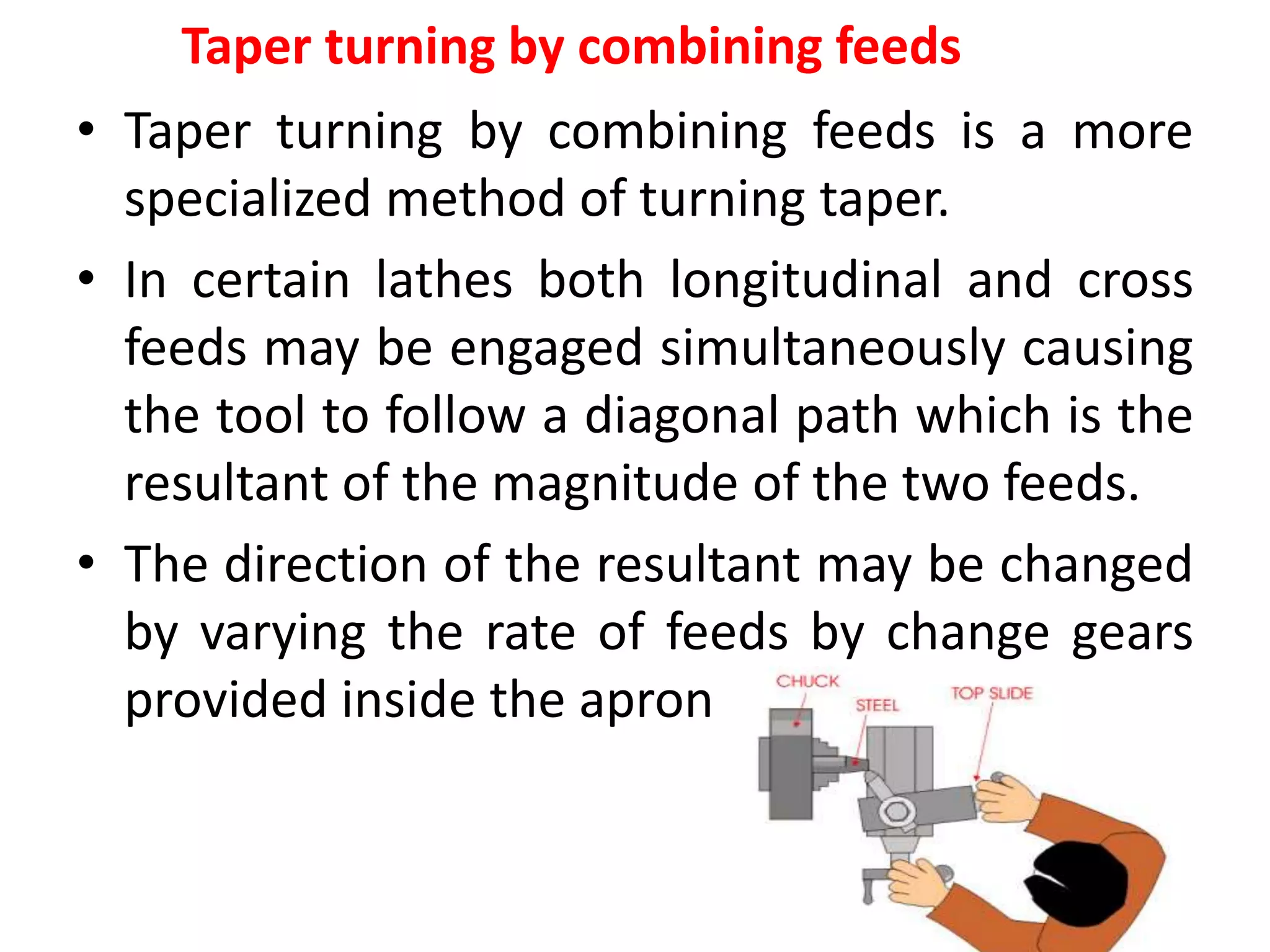
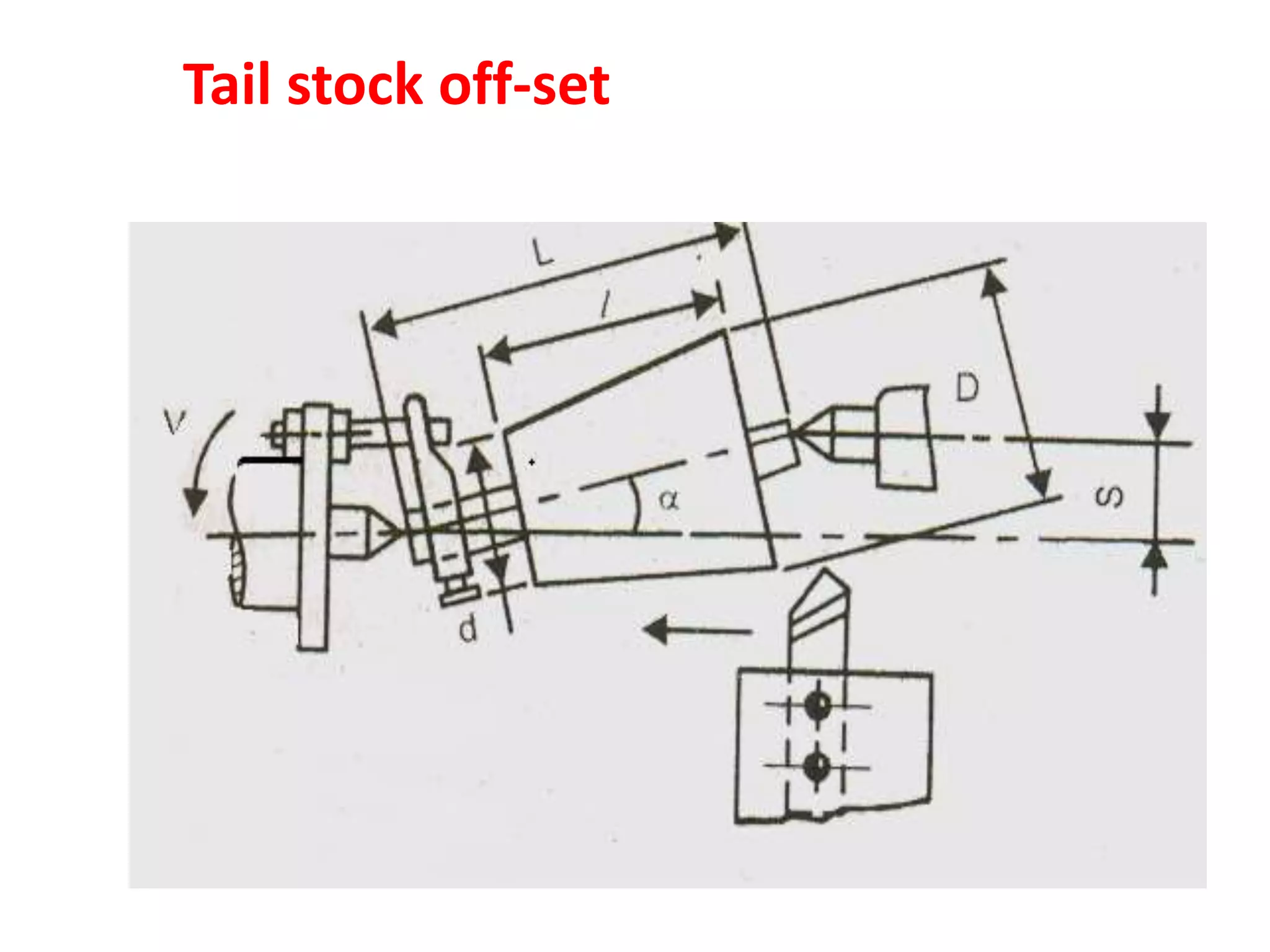
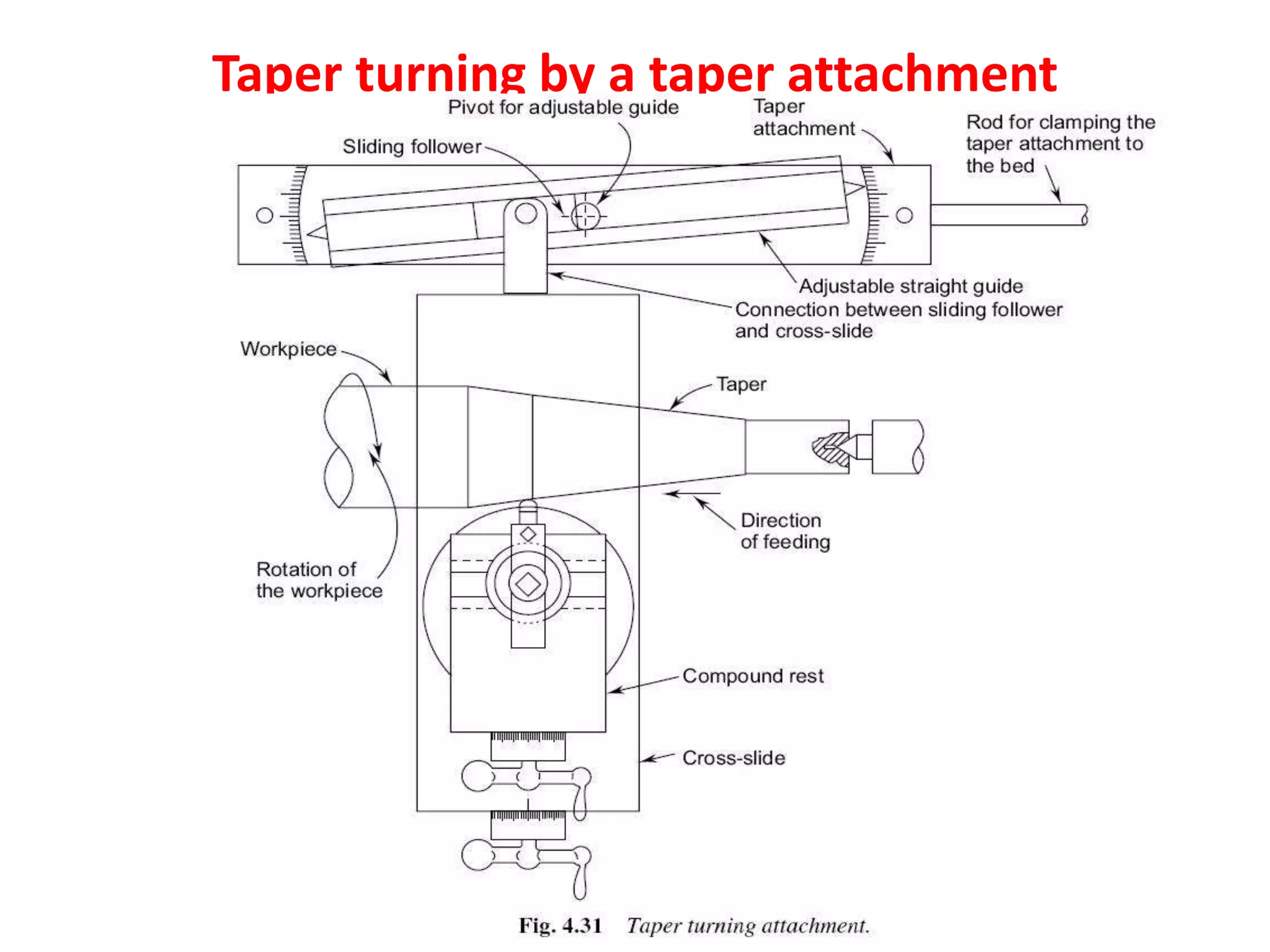
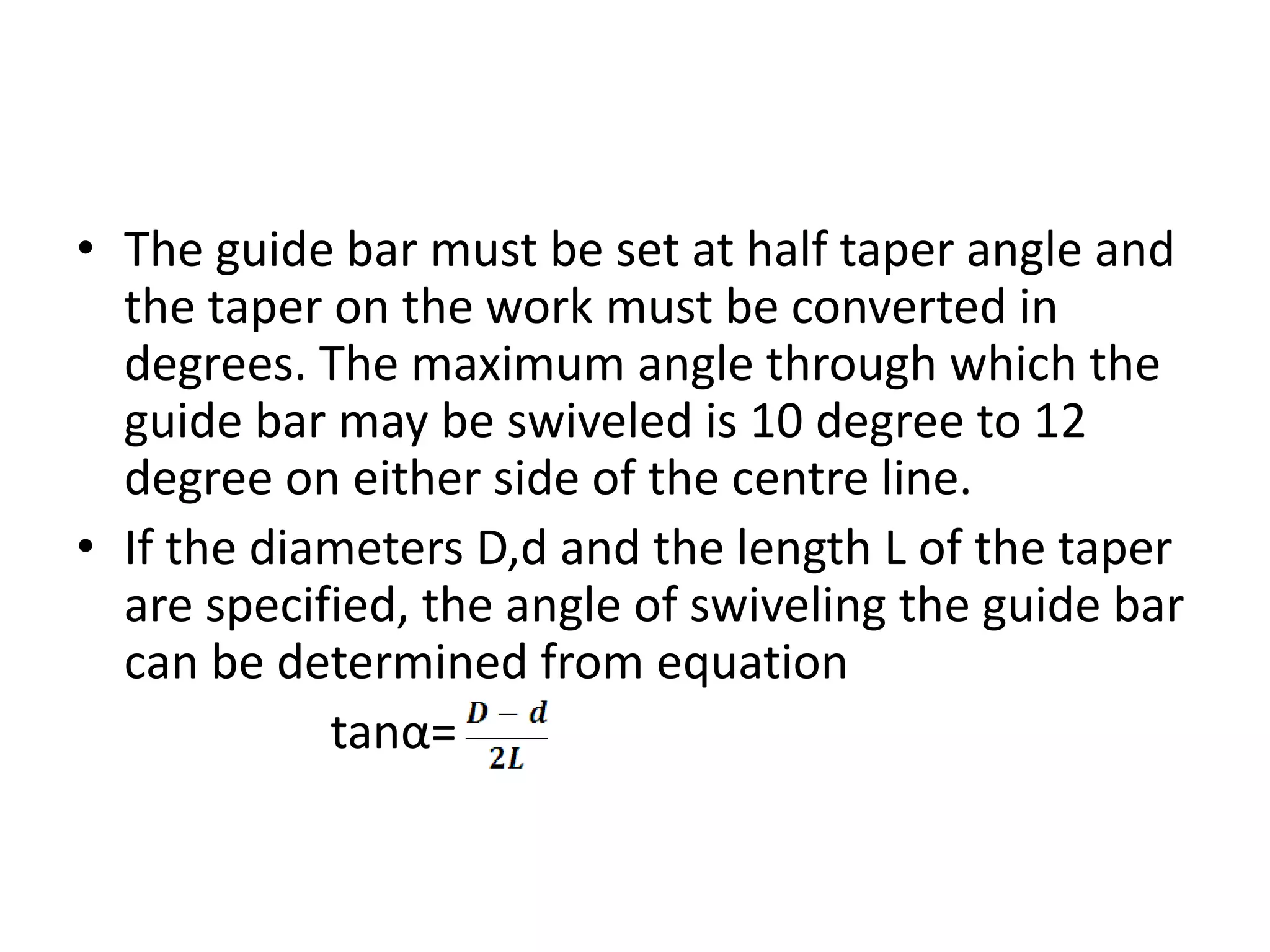
Methods and calculations involved in taper turning, including taper definition and various techniques.
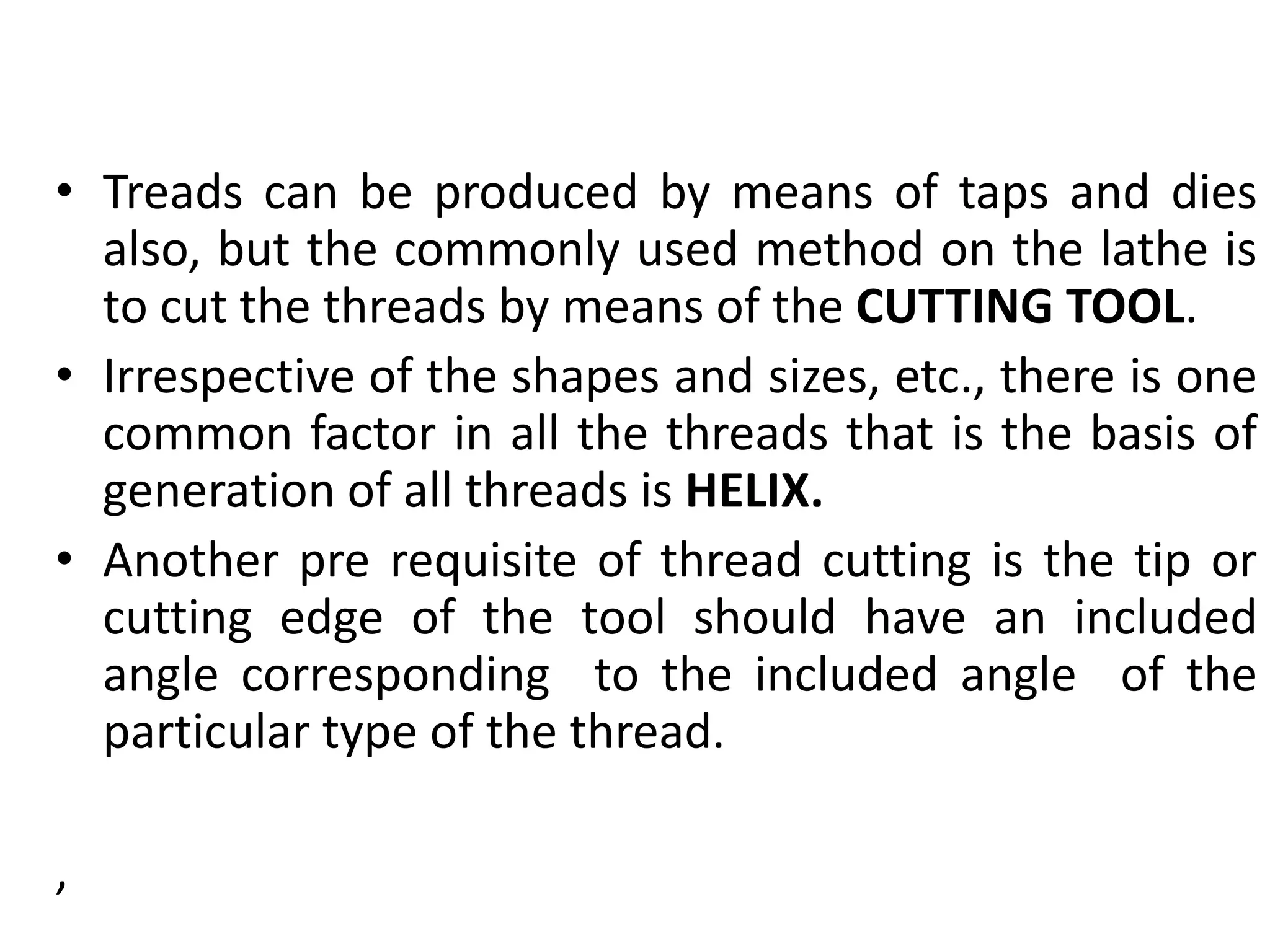
Overview of thread cutting methods and essential elements such as pitch, diameter, and lead in threading.
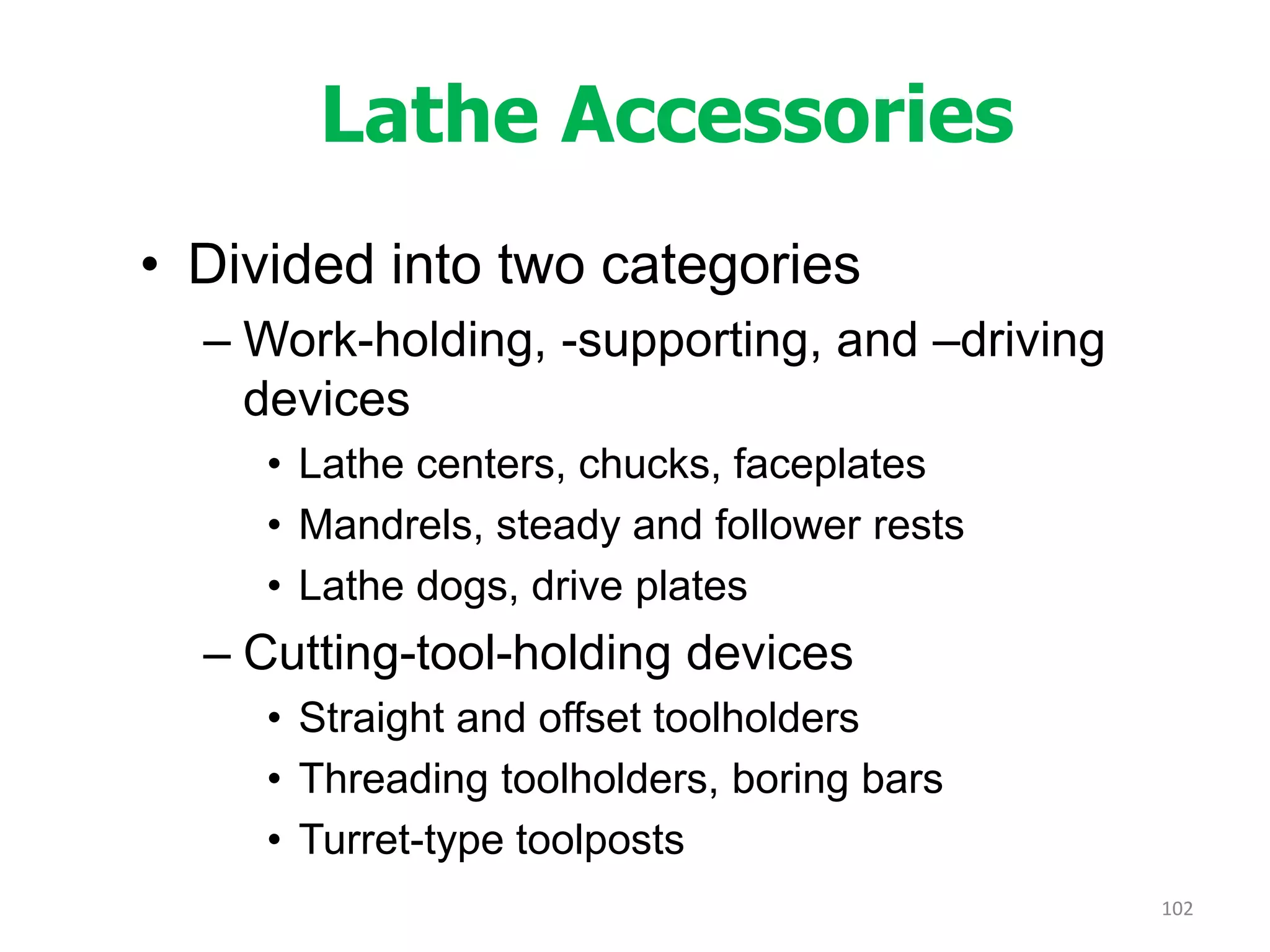
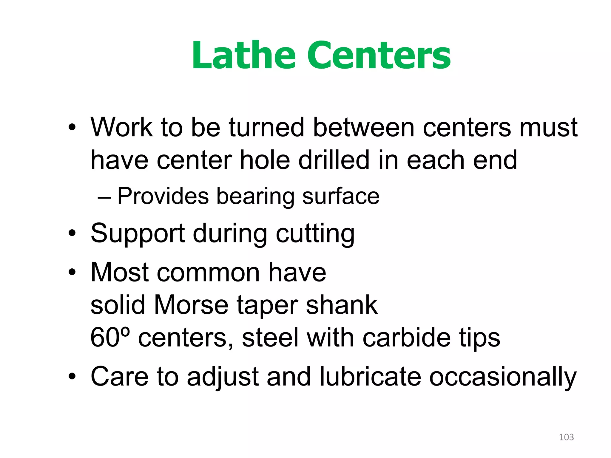
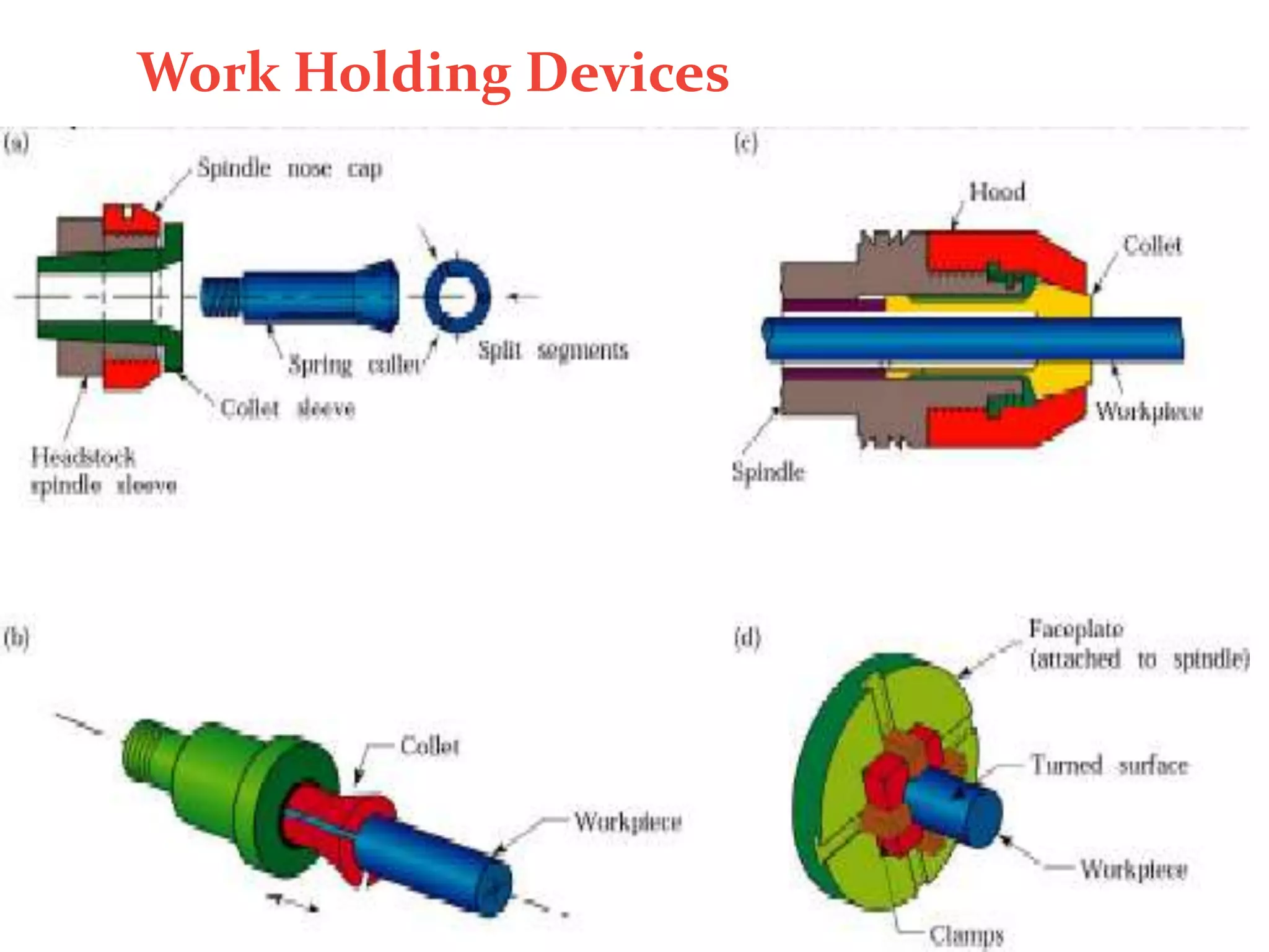
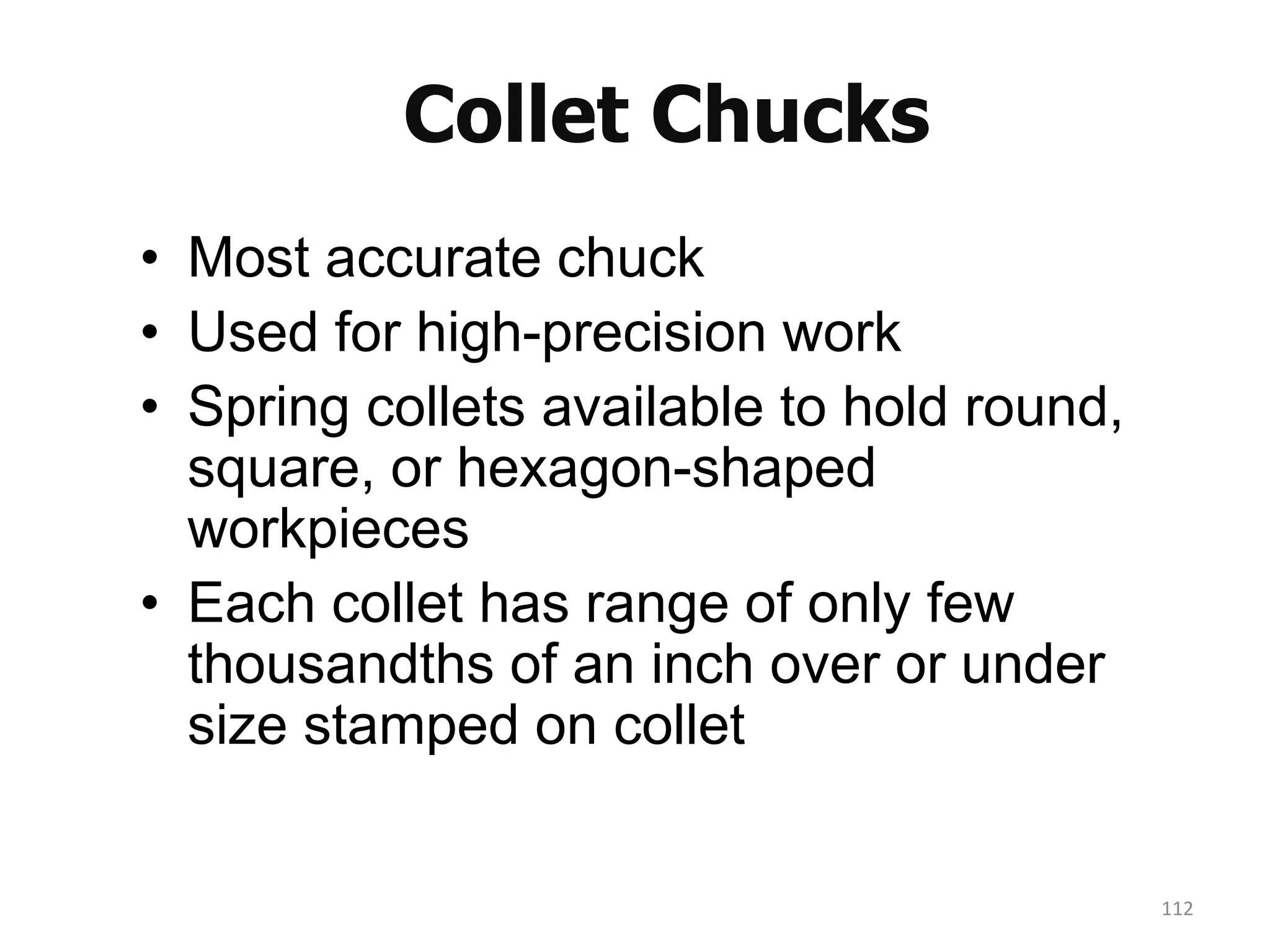
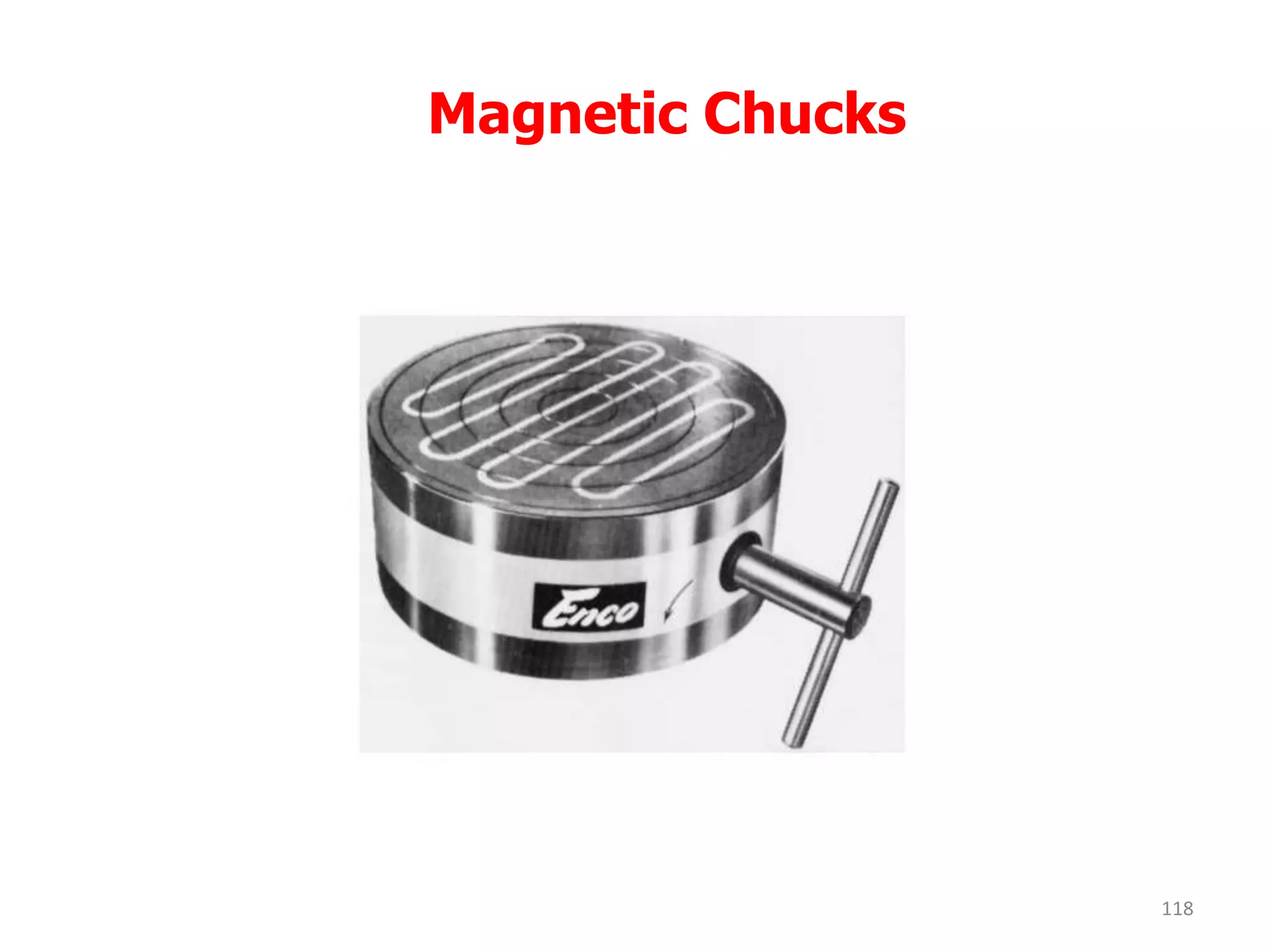
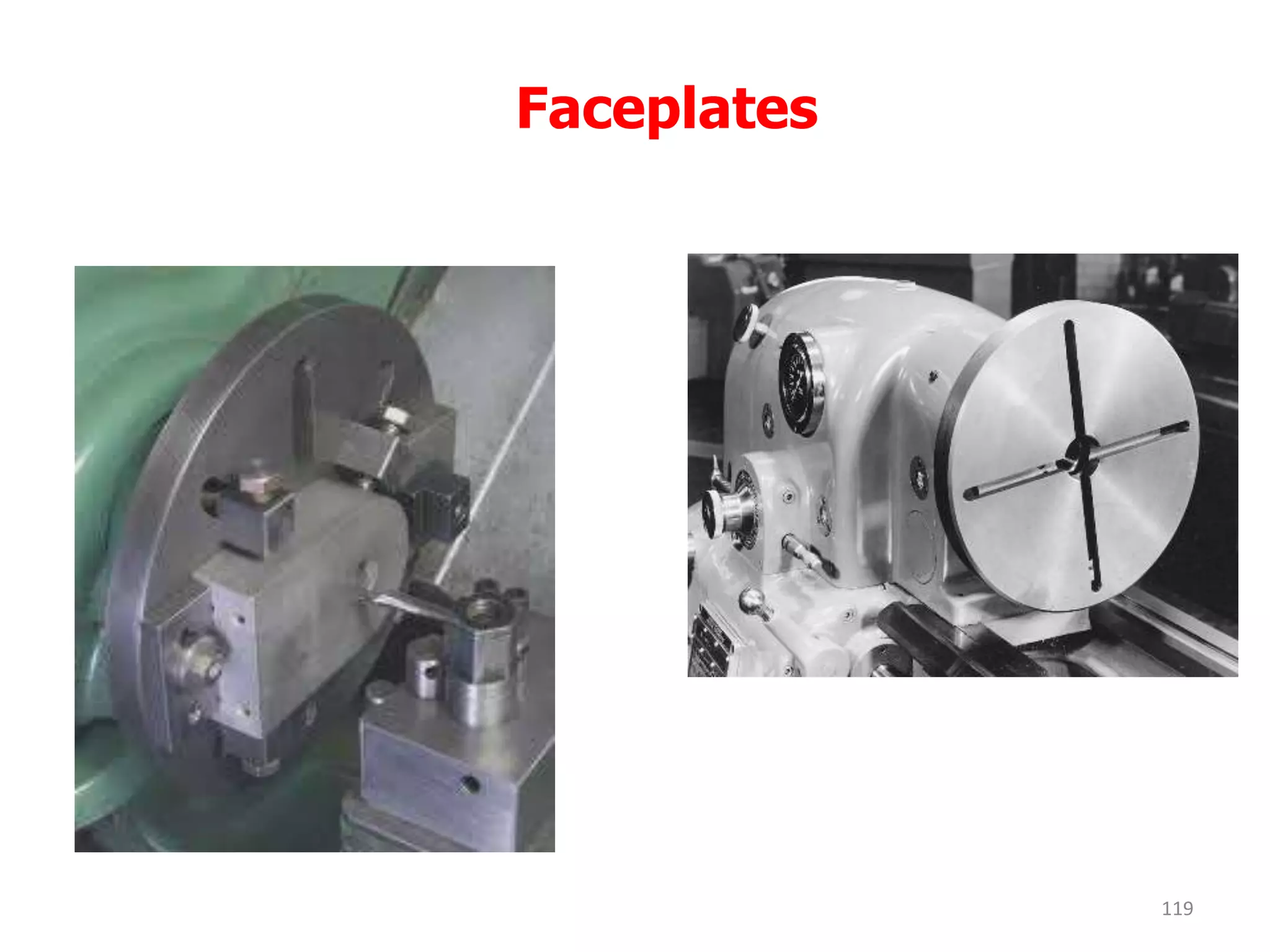
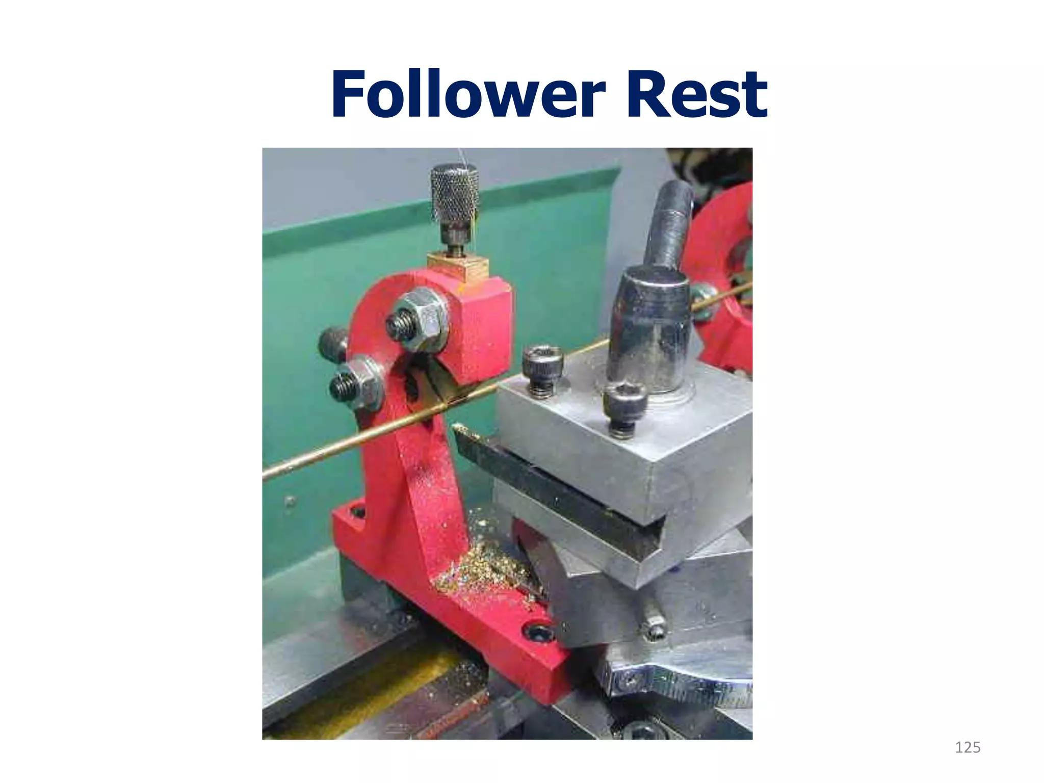
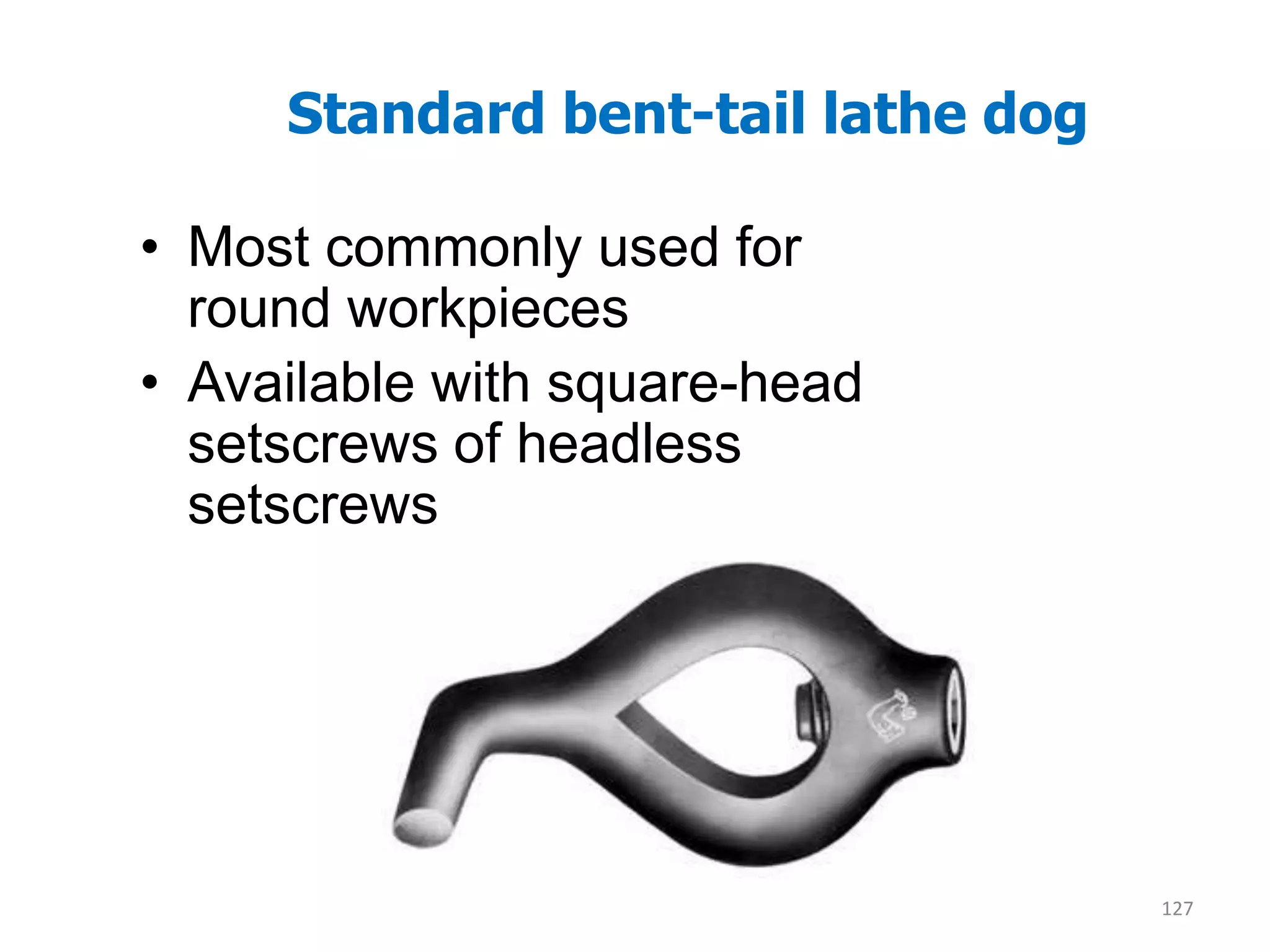
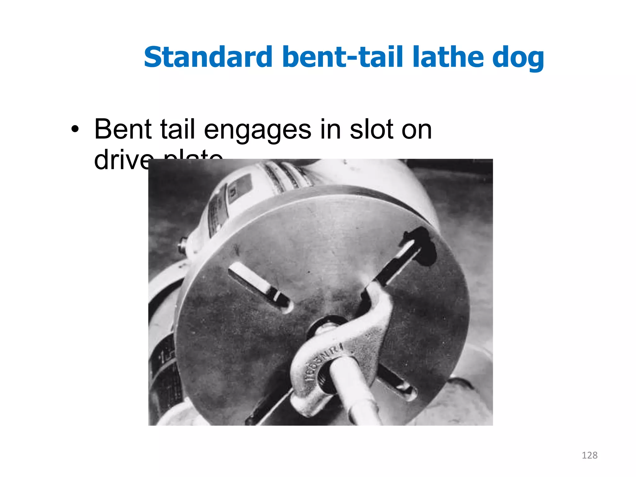
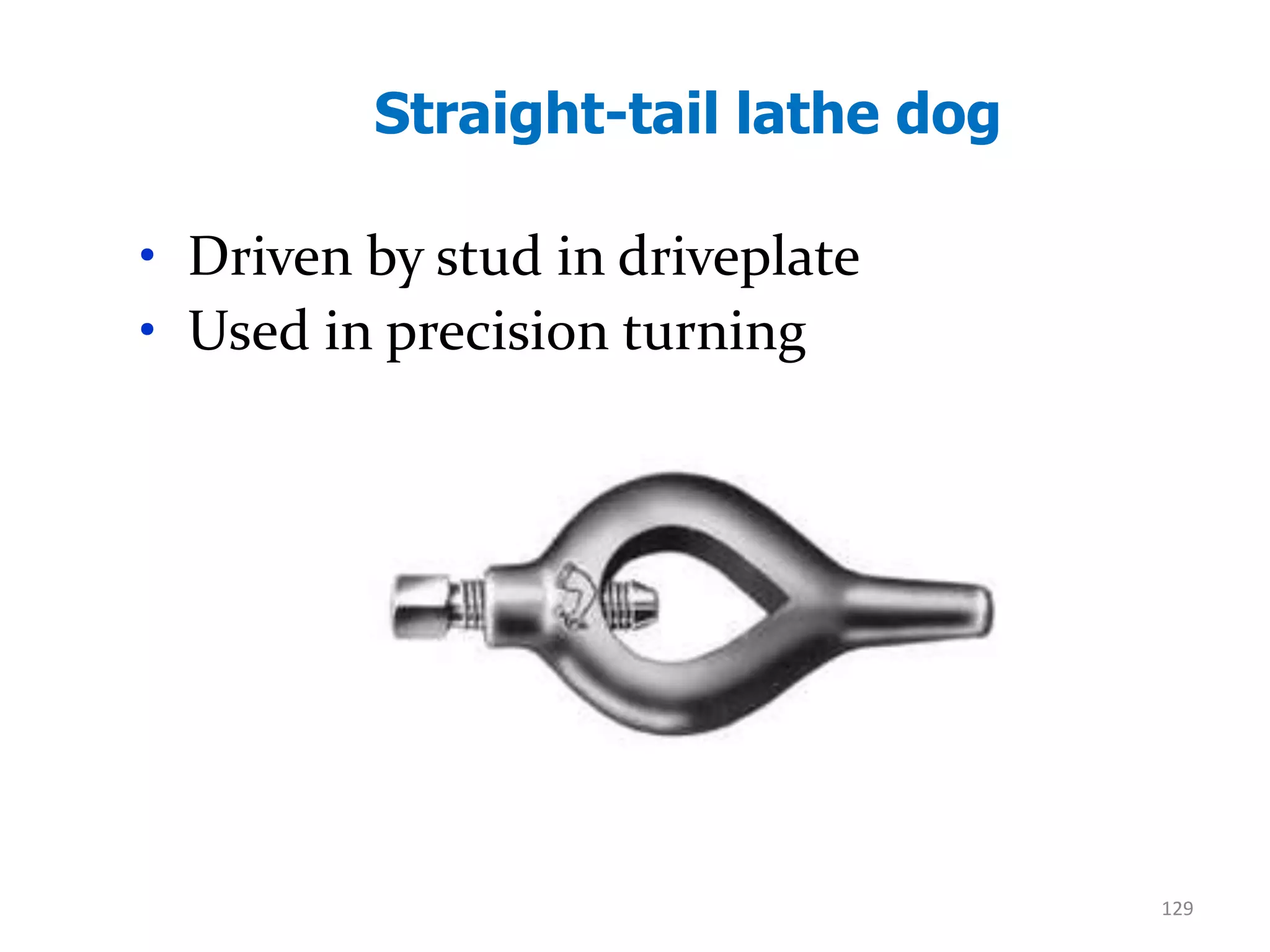
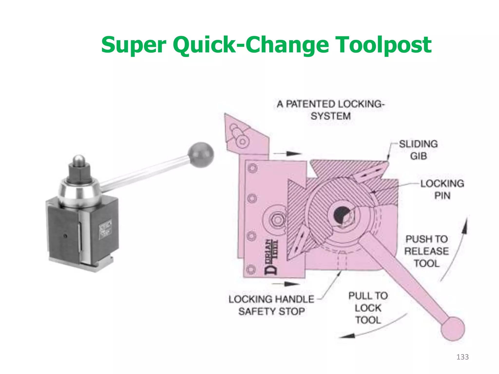
Description of various lathe accessories, including work holding and cutting tool holding devices.
Summarizes key points about lathe operations, accessories, and various machining processes and methods.


![1. SIH2025-IDEA-Presentation-Format[1].pptx](https://cdn.slidesharecdn.com/ss_thumbnails/1-251204091914-b1bb69d5-thumbnail.jpg?width=640&height=640&fit=bounds)


