The Confined Masonry Initiative
•
4 likes•1,165 views

The Confined Masonry Initiative

Recommended
Recommended
More Related Content
Viewers also liked
Viewers also liked (7)
Similar to The Confined Masonry Initiative
Similar to The Confined Masonry Initiative (20)
More from Global Risk Forum GRFDavos
More from Global Risk Forum GRFDavos (20)
Recently uploaded
Recently uploaded (20)
The Confined Masonry Initiative
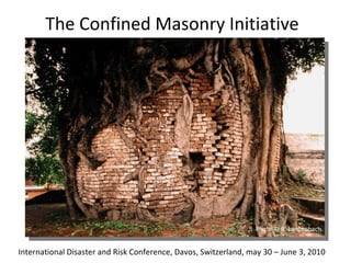
- 1. The Confined Masonry Initiative International Disaster and Risk Conference, Davos, Switzerland, may 30 – June 3, 2010 Photo © R. Langenbach
- 2. The Confined Masonry Initiative International Disaster and Risk Conference, Davos, Switzerland, may 30 – June 3, 2010 Photo © R. Langenbach presented by Sahar Safaie, Consultant, Vancouver, Canada Svetlana Brzev, British Columbia Institute of Technology, Vancouver, Canada Marjorie Greene, EERI, Oakland, California Marcial Blondet, Catholic University of Peru, Lima, Peru Roberto Meli, National Autonomous University of Mexico, Mexico D.F., Mexico Jonathan Galindo, Catholic University of Peru, Lima, Peru Sudhir Jain , Indian Institute of Technology Gandhinagar, Ahmedabad, India Tom Schacher, Swiss Agency for Development and Cooperation, Switzerland (presenter)
- 3. RC moment frames vs Confined Masonry RC columns first, walls later CM walls first, columns later
- 4. RC moment frames vs Confined Masonry RC columns first, walls later CM walls first, columns later
- 8. RC frames in low-tech environments (Several or all of these conditions apply)
- 9. Typical problems with concrete works
- 10. RC frames are too complex For safe construction simpler systems are needed Confined Masonry is one of them
- 11. RC moment frames vs Confined masonry RC Complex CM Simple Load paths (poetically speaking…)
- 12. Pakistan Pakistan Pakistan Indonesia Construction of CM buildings
- 13. Pakistan Slovenia Pakistan Indonesia Low rise CM buildings
- 14. Peru Chile Chile Research by M. Tomasevic, Slovenia CM buildings after a quake
- 15. Mexico © R. Langenbach Chile Chile Medium rise buildings Chile
- 16. 2 nd CM Network meeting Peru 2009 1 st CM Network meeting India 2008 China China USA India Mexico India USA Switzerland Argentina USA Peru Canada Chile Peru India India India India Switzerland India USA USA/Iran France/Algeria Peru USA Slovenia Canada USA USA/Iran India India India India
- 17. Compilation and analysis of existing material
- 18. Confined Masonry DESIGN Guideline, Draft Downloadable at www.confinedmasonry.org
- 19. Confined Masonry CONSTRUCTION Guideline, ‘under construction’
- 20. Promotion through the internet
- 21. Demo building Full scale training models On the job training Training of inspectors Post EQ opportunities: Practical training
- 22. CM training necessary even where already in use
- 23. Confined Masonry RESEARCH NEEDS
- 24. Research example: need for seismic bands ?
- 26. Thank you and
Editor's Notes
- Confined Masonry is a system where the masonry walls bear the vertical loads as well as the horizontal loads which occur during an earthquake. These masonry walls are tied down by ‘ties’. We do not use the word columns because conceptually speaking these ties are not load-bearing, but work purely under traction.
- Confined Masonry is a system where the masonry walls bear the vertical loads as well as the horizontal loads which occur during an earthquake. These masonry walls are tied down by ‘ties’. We do not use the word columns because conceptually speaking these ties are not load-bearing, but work purely under traction.
- We can’t speak about CM without speaking about RC. These systems look very similar to an untrained eye, but are profoundly different in their concept and behaviour. The easiest way to explain CM to a broad public is to say that in RC, columns are built first, and in CM walls are built first, then the ties (not columns) are poured in.
- Left: In RC systems calculations, walls are not taken into account. In fact, they are considered a disturbance (e.g. short column effects). Engineers would like to have them well separated from the frame system (i.e. the columns and beams), whereas architects want to stick them together because they are building rooms, not structural systems. Masons obviously ‘stick’ them together (the word ‘stick’ is important here because workers consider concrete as a kind of glue that holds everything together). Right: The CM system is based on load-bearing walls which are held together by RC ties. Because these ties are not load-bearing we avoid the use of the word ‘columns’. The wall-vertical tie connection is typically toothed to ensure a good adherence of the ties to the load-bearing walls.
- RC moment frames are hi-tech. They are much more difficult to make properly than we are used to think. For engineers and architects being used to work in an environment where the workforce is well trained, and where building sites are regularly supervised by an engineer, it is difficult to imagine how many things can go wrong with Reinforced Concrete. Let’s looks at the various components steel, concrete and formwork. We should also mention the importance of the right structural concept (not ensured when no engineer has ever looked into it) As well as the issue of walls which is often ignored even by engineers.
- In third world cities, engineers are active in the city centre where they work on high rise buildings. The vast periphery of 1-3 or 4 story houses is build by contractors without engineers. They ‘know’ how to make buildings, and clients can save money on engineers. This even in EQ prone countries!
- A typical third world city where buildings go up without control of any sort. Here we see a lot of unreinforced masonry. CM, being simpler and cheaper than RC frames, is also trying to provide an answer to these extremely vulnerable constructions.
- In such environments, RC is poor because some or all of these conditions for proper RC are not met.
- Some examples of RC frame problems: Top from left to right: Rebars not bent into the knot, Rebars in the wrong place or insufficient in number, corner detail weak, steel of bad quality (re-melted steel). Bottom from left to right: No concrete cover, agglomerates the wrong size, un-tight form work, insufficient number of stirrups (this picture from Italy)
- RC moment frames are dangerous when made by untrained workers, insufficient supervision (engineers consider their job done, when the drawings leave their office), High material and low wage costs (induces cheating)
- CM is more tolerant to errors because its concept is simpler: - Walls bear the loads (vertical and horizontal) Steel keep the walls together, like a string around a parcel. Connections can be simpler because there is no moment (because there is no frame).
- Some illustrations of CM: Bottom left: a demo building SDC has built in Pakistan for on-the-job training of workers. Bottom right: Notice the reinforcement ties in the gable walls.
- Examples of low rise buildings: Top left: demo building in Pakistan. CM was not known before the 2005 earthquake reconstruction phase. Top right: a house in Slovenia where CM is quite well known and used. Bottom left: CM in Indonesia where CM is known, but often of bad quality. BuildChange provided training to improve knowhow. Bottom right: CM in Pakistan is now becoming fashionable and has entered the building code.
- Examples of low rise buildings: Top left: CM in Peru after the latest earthquake. The house on the right has collapsed, while the CM building has survived without major damage. Top right: CM building after the latest Chile EQ: no damage. Bottom left: Some damage in a CM building in Chile after the latest quake. Such diagonal cracks are less dramatic in CM because the walls remain load-bearing until the final collapse (as long as solid bricks or blocks are used. Hollow bricks are not allowed in CM, but are frequently used in RC where walls ‘explode’ and kill people). Bottom right: a typical hysteresis curve of non reinforced masonry which supports very little lateral displacement. (picture has been compressed to show the same scale as next pic. Next: a hysteresis curve of CM: CM supports a lot of lateral displacement before failing.
- Examples of medium rise CM buildings.
- The Confined Masonry Network group. We have decided to promote CM: Where it is not yet known. Where it is known but badly used. Undertake research on topics which are not yet clear. Develop internationally accepted standards And anybody new is welcome.
- We have collected all existing material For analyses (of content and form. This last point is important as we want to address the right people in the right language, engineers, architects, technicians, workers, authorities, etc) for synthesis in order to develop ‘universally’ acceptable guidelines.
- A ‘universal’ Design Guideline has been developed and does currently exist in its draft version. It can be downloaded for review on www.confinedmasonry.org. Any comments are welcome.
- Equally a ‘universal’ Construction Guideline is under development. It will cover the whole construction process through very explicit drawings.
- The CM Network is promoting CM on the internet on various sites: Top left: NICEE, the Indian National Information Centre for Earthquake Engineering. Top right: The Confined Masonry Network site. Bottom left: The World Housing Encyclopaedia Bottom right: Build Change social enterprise active in Indonesia, China and now Haiti.
- Post-earthquakes reconstruction phases are great opportunities to promote safer building techniques. Here some pictures from Pakistan showing various promotion methods: Demo buildings Full scale models in villages where people can come and check how detailing should be done. On the job training Training of building inspectors, here the Pakistani army which had a very important role in the distribution of carrots or sticks (i.e. government subsidies)
- CM is not perfect everywhere. Here some examples of deficient detailing, particularly in the tie-column-tie beam connections. Also problems of wall buckling due to out of plane solicitation. On this last point we still need more information and research, which brings us to the next point:
- Research is still needed. We don’t know everything! This list can be downloaded from our site. We welcome anybody willing to participate in the research of answers to our questions.
- Example of research need: Do we need intermediate seismic bands in the walls, particularly when the walls are very thin (1/2 bricks) or made with low quality bricks?
- Our site.