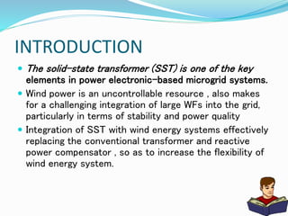
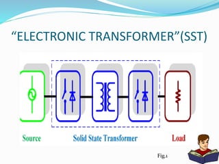
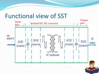
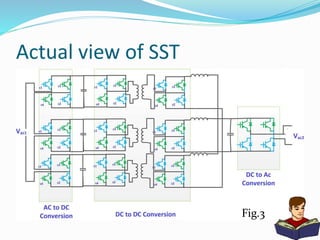
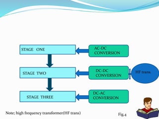
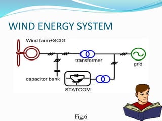
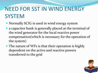
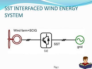
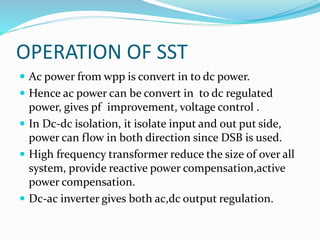
CONTENTS
 INTRODUCTION
 SOLID STATE TRANSFORMER(SST)
 NEED FOR SST IN WIND ENERGY
SYSTEM
 SST INTERFACED WIND ENERGY
SYSTEM
 CONCLUSION
INTRODUCTION
 The solid-state transformer (SST) is one of the key
elements in power electronic-based microgrid systems.
 Wind power is an uncontrollable resource , also makes
for a challenging integration of large WFs into the grid,
particularly in terms of stability and power quality
 Integration of SST with wind energy systems effectively
replacing the conventional transformer and reactive
power compensator , so as to increase the flexibility of
wind energy system.
Solid state transformer
 The basic idea of the SST is to achieve the voltage
transformation by medium to high frequency
isolation, therefore to potentially reduce the volume
and weight of it compared with the traditional power
transformer.
“ELECTRONIC TRANSFORMER”(SST)
Fig.1
Key components
 High frequency transformers
 Power electronics converters
*AC to DC converters
*DC to DC converters
*AC to DC inverter
Functional view of SST
Input
part
Isolated DC-DC converter
Output
part
AC
INPUT
Actual view of SST
Fig.3
STAGE ONE
STAGE TWO
STAGE THREE
AC-DC
CONVERSION
DC-DC
CONVERSION
DC-AC
CONVERSION
Fig.4
HF trans.
Note; high frequency transformer(HF trans)
STAGE ONE
 In this stage is a three-phase ac/dc rectifier that
regulates a high-voltage dc bus (and ac voltage when
for reactive power compensation) is used.
 It produce low distortion grid current.
 DC voltage regulation.
STAGE TWO
1) consists of a Dual active bridge(DAB), a high-
frequency transformer.
 DAB converter gives;
1) electrical isolation
2) high reliability
3) ease of realizing
4) soft-switching control
5) complete symmetry of configuration that allows
seamless control for bidirectional power flow.
 Active power flows from the bridge with leading phase
angle to the bridge with lagging phase angle.
 primary bridge leading secondary bridge by a phase
angle of ϕ, the power flows from the primary to the
secondary.
STAGE THREE
 DC-AC converter is used to convert the dc voltage in
desirable voltage.
ADVANTAGE
 An excellent utilization of distributed renewable
energy resources and distributed energy storage
devices.
 Power factor control.
 Fast isolation under fault conditions due to a
controlled SST.
 Control of both AC and DC loads can be done using
the SST
WIND ENERGY SYSTEM
Fig.6
NEED FOR SST IN WIND ENERGY
SYSTEM
 Normally SCIG is used in wind energy system
 a capacitor bank is generally placed at the terminal of
the wind generator for the local reactive power
compensation(which is necessary for the operation of
the system)
 The nature of WFs is that their operation is highly
dependent on the active and reactive powers
transferred to the grid
 In any interfacing system there is need for
conventional transformer and reactive power
compensator.
 SST-interfaced WF architectures effectively replacing
the conventional transformer and reactive power
compensator.
SST INTERFACED WIND ENERGY
SYSTEM
Fig.7
 The local capacitor bank, two conventional
transformers, and the STATCOM are all functionally
integrated into a single SST
 From the working of SST, it is revealed that reactive
power compensation, active power compensation and
voltage conversion can be done by SST.
OPERATION OF SST
 Ac power from wpp is convert in to dc power.
 Hence ac power can be convert in to dc regulated
power, gives pf improvement, voltage control .
 In Dc-dc isolation, it isolate input and out put side,
power can flow in both direction since DSB is used.
 High frequency transformer reduce the size of over all
system, provide reactive power compensation,active
power compensation.
 Dc-ac inverter gives both ac,dc output regulation.
CONCLUSION
 Energy crisis calls for a large penetration of renewable
energy resources, among which wind energy is a
promising one. Voltage and frequency regulation is
vital to meet the grid code.
 SST solve almost problems that make this system
cannot connect to grid .
REFERENCES
 Xu She, Alex Q. Huang, Fei Wang and Rolando Burgos” Wind Energy System With Integrated
Functions of Active Power Transfer, Reactive Power Compensation, and Voltage Conversion”- IEEE
TRANSACTIONS ON INDUSTRIAL ELECTRONICS, VOL. 60, NO. 10, OCTOBER 2013
 Hengsi Qin,and Jonathan W. Kimball,” Solid-State Transformer Architecture Using AC–AC Dual-
Active-Bridge Converter”- IEEE TRANSACTIONS ON INDUSTRIAL ELECTRONICS, VOL. 60, NO. 9,
SEPTEMBER 2013
 Jianjiang Shi, Wei Gou, Hao Yuan, Tiefu Zhao and Alex Q.” Research on Voltage and Power Balance
Control for Cascaded Modular Solid-State Transformer” IEEE TRANSACTIONS ON POWER
ELECTRONICS, VOL. 26, NO. 4, APRIL 2011
 R. Vibin1, K. Malarvizhi2” Power Flow Control Scheme for Wind Energy Conversion System using
FACTS Controller” International Journal of Modern Engineering Research (IJMER) Vol.2, Issue.3,
May-June 2012 pp-644-648
 Nijaz Dizdarevic* and Matislav Majstrovic” Reactive power compensation of wind energy conversion
system by using Unified Power Flow Controller” Int. J. Energy Technology and Policy, Vol. 3, No. 3,
2005
 Xu She1, Alex Huang and Rolando Burgos2” Review of the Solid State Transformer Technologies and
its Application in Power Distribution System”
 Gary L. Johnson” WIND ENERGY SYSTEMS” Electronic Edition
Solid state transformer ppt

Solid state transformer ppt

  • 3.
    CONTENTS  INTRODUCTION  SOLIDSTATE TRANSFORMER(SST)  NEED FOR SST IN WIND ENERGY SYSTEM  SST INTERFACED WIND ENERGY SYSTEM  CONCLUSION
  • 4.
    INTRODUCTION  The solid-statetransformer (SST) is one of the key elements in power electronic-based microgrid systems.  Wind power is an uncontrollable resource , also makes for a challenging integration of large WFs into the grid, particularly in terms of stability and power quality  Integration of SST with wind energy systems effectively replacing the conventional transformer and reactive power compensator , so as to increase the flexibility of wind energy system.
  • 5.
    Solid state transformer The basic idea of the SST is to achieve the voltage transformation by medium to high frequency isolation, therefore to potentially reduce the volume and weight of it compared with the traditional power transformer.
  • 6.
  • 7.
    Key components  Highfrequency transformers  Power electronics converters *AC to DC converters *DC to DC converters *AC to DC inverter
  • 8.
    Functional view ofSST Input part Isolated DC-DC converter Output part AC INPUT
  • 9.
    Actual view ofSST Fig.3
  • 10.
    STAGE ONE STAGE TWO STAGETHREE AC-DC CONVERSION DC-DC CONVERSION DC-AC CONVERSION Fig.4 HF trans. Note; high frequency transformer(HF trans)
  • 11.
    STAGE ONE  Inthis stage is a three-phase ac/dc rectifier that regulates a high-voltage dc bus (and ac voltage when for reactive power compensation) is used.  It produce low distortion grid current.  DC voltage regulation.
  • 12.
    STAGE TWO 1) consistsof a Dual active bridge(DAB), a high- frequency transformer.  DAB converter gives; 1) electrical isolation 2) high reliability 3) ease of realizing 4) soft-switching control 5) complete symmetry of configuration that allows seamless control for bidirectional power flow.
  • 13.
     Active powerflows from the bridge with leading phase angle to the bridge with lagging phase angle.  primary bridge leading secondary bridge by a phase angle of ϕ, the power flows from the primary to the secondary.
  • 14.
    STAGE THREE  DC-ACconverter is used to convert the dc voltage in desirable voltage.
  • 15.
    ADVANTAGE  An excellentutilization of distributed renewable energy resources and distributed energy storage devices.  Power factor control.  Fast isolation under fault conditions due to a controlled SST.  Control of both AC and DC loads can be done using the SST
  • 16.
  • 17.
    NEED FOR SSTIN WIND ENERGY SYSTEM  Normally SCIG is used in wind energy system  a capacitor bank is generally placed at the terminal of the wind generator for the local reactive power compensation(which is necessary for the operation of the system)  The nature of WFs is that their operation is highly dependent on the active and reactive powers transferred to the grid
  • 18.
     In anyinterfacing system there is need for conventional transformer and reactive power compensator.  SST-interfaced WF architectures effectively replacing the conventional transformer and reactive power compensator.
  • 19.
    SST INTERFACED WINDENERGY SYSTEM Fig.7
  • 20.
     The localcapacitor bank, two conventional transformers, and the STATCOM are all functionally integrated into a single SST  From the working of SST, it is revealed that reactive power compensation, active power compensation and voltage conversion can be done by SST.
  • 21.
    OPERATION OF SST Ac power from wpp is convert in to dc power.  Hence ac power can be convert in to dc regulated power, gives pf improvement, voltage control .  In Dc-dc isolation, it isolate input and out put side, power can flow in both direction since DSB is used.  High frequency transformer reduce the size of over all system, provide reactive power compensation,active power compensation.  Dc-ac inverter gives both ac,dc output regulation.
  • 22.
    CONCLUSION  Energy crisiscalls for a large penetration of renewable energy resources, among which wind energy is a promising one. Voltage and frequency regulation is vital to meet the grid code.  SST solve almost problems that make this system cannot connect to grid .
  • 23.
    REFERENCES  Xu She,Alex Q. Huang, Fei Wang and Rolando Burgos” Wind Energy System With Integrated Functions of Active Power Transfer, Reactive Power Compensation, and Voltage Conversion”- IEEE TRANSACTIONS ON INDUSTRIAL ELECTRONICS, VOL. 60, NO. 10, OCTOBER 2013  Hengsi Qin,and Jonathan W. Kimball,” Solid-State Transformer Architecture Using AC–AC Dual- Active-Bridge Converter”- IEEE TRANSACTIONS ON INDUSTRIAL ELECTRONICS, VOL. 60, NO. 9, SEPTEMBER 2013  Jianjiang Shi, Wei Gou, Hao Yuan, Tiefu Zhao and Alex Q.” Research on Voltage and Power Balance Control for Cascaded Modular Solid-State Transformer” IEEE TRANSACTIONS ON POWER ELECTRONICS, VOL. 26, NO. 4, APRIL 2011  R. Vibin1, K. Malarvizhi2” Power Flow Control Scheme for Wind Energy Conversion System using FACTS Controller” International Journal of Modern Engineering Research (IJMER) Vol.2, Issue.3, May-June 2012 pp-644-648  Nijaz Dizdarevic* and Matislav Majstrovic” Reactive power compensation of wind energy conversion system by using Unified Power Flow Controller” Int. J. Energy Technology and Policy, Vol. 3, No. 3, 2005  Xu She1, Alex Huang and Rolando Burgos2” Review of the Solid State Transformer Technologies and its Application in Power Distribution System”  Gary L. Johnson” WIND ENERGY SYSTEMS” Electronic Edition