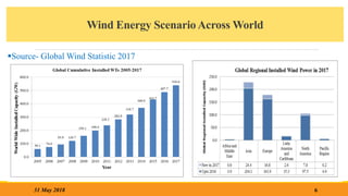
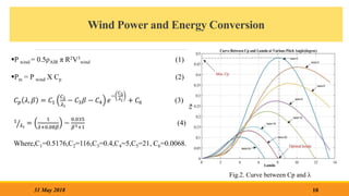
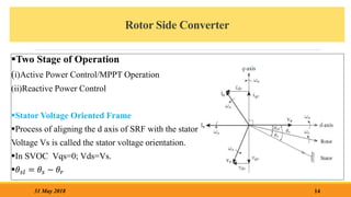
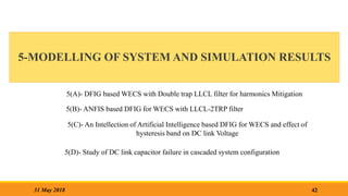
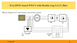
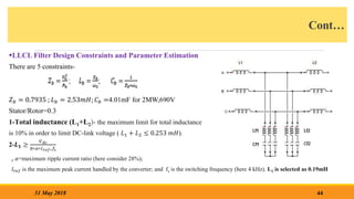
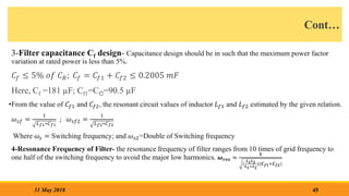
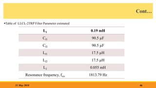
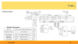
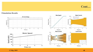
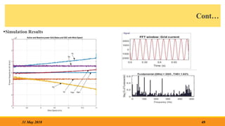
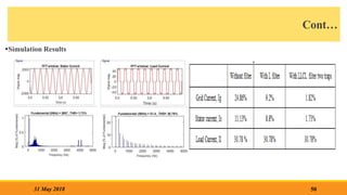
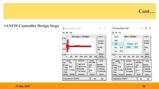
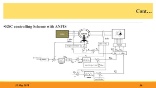
The document presents a work proposal for an M.Tech thesis on analyzing DFIG-based wind energy conversion systems for harmonic mitigation using PI and ANFIS control. The objectives are to design an LLCL-2 TRP filter for harmonics mitigation, compare PI and ANFIS controllers for DFIG active and reactive power control, model the RSC and GSC in MATLAB, and study the effects of non-linear loads and DC link faults. The literature review covers technical issues in wind farm development, renewable technologies, wind energy scenarios in India and globally, DFIG configurations, MPPT techniques, DFIG modeling, and prior work on filters and control methods for harmonics mit


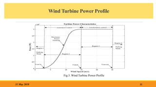

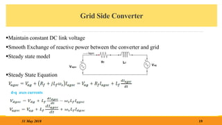


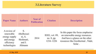

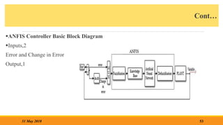
![5(B)-ANFIS based DFIG for WECS with LLCL-2 Filter
Neural Network require long time in training & convergence[17-18]
Fuzzy and Neural combined effect provide fast convergence and improved performance.
Advantage of ANFIS
Simple and Low cost hardware
Easy Implementation
Robustness
Tuning
51
31 May 2018](https://image.slidesharecdn.com/workproposalpresentation-240108103735-448ff1c2/85/work-proposal-presentation-pptx-thesis-new-51-320.jpg)


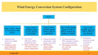
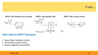
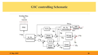
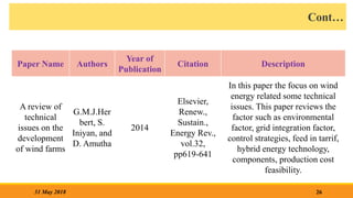
![5(c) ANFIS based System and effect of Hysteresis band on DC link
Voltage
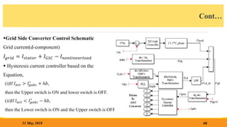
In [16] Author proposes the indirect current control for GSC .
59
31 May 2018](https://image.slidesharecdn.com/workproposalpresentation-240108103735-448ff1c2/85/work-proposal-presentation-pptx-thesis-new-59-320.jpg)

![References
[1] S. Abolhessini, A.heshmati, and J.Altmann, “ A review of renewable energy supply and energy
efficiency technologies”, discussion paper no-8145 April-2014, Institute for the study of labor
(IZA)
[2] G.M.J.Herbert, S. Iniyan, and D. Amutha, “ A review of technical issues on the development of
wind farms”, Renew., Sustain., Energy Rev., vol.32, pp619-641,2014.
[3] I. Munteanu, A. I. Bratcu, N. A. Cutululis, and E.Ceang, “Optimal Control of Wind Energy
Systems Towards a Global Approach”, Springer-Verlag London Limited,2008.
[4] Global Wind Report 2016: Annual Market Update, ‘Global Wind Energy Council’, accessed on
August 2017, [Online].Available:https://www.gwec.net.
[5] T. Ackermann, ‘‘Wind Power in Power System”, Wiley,2005.
[6] T.Burton, D.Sharpe, N.Jenkins, and E. Bossanyi, Wind Energy Handbook, Wiley,2001.
[7] B. Wu, N. Zargari, S. Kouro, Y. Lang, “Power Conversion and Control of Wind Energy
Systems”, Wiley 2011.
[8]G.Abad, J.Lopez, M.A.Rodriguez, L. Marroyo, G.Iwanski, “Doubly Fed Induction machine-
Modeling and Control of Wind Energy Generation”, Wiley Publication-2011.
78
31 May 2018](https://image.slidesharecdn.com/workproposalpresentation-240108103735-448ff1c2/85/work-proposal-presentation-pptx-thesis-new-78-320.jpg)
![Cont…
[9] G. O. Suvire and P. E. Mercado, “combined control of a distribution static synchronous
compensator/ flywheel energy storage system for wind energy applications,” IET Gen. Trans. &
Distr., vol.6, no.6, pp.483-492, June 2012.
[10] D.Somayajula and M.L.Crow, “ An Ultra Capacitor integrated power conditioner for
intermittency smoothing and improving power quality of distribution grid”, IEEE
Trans.Sust.Energy,vol.5,no.4,Oct 2014,pp.1145-1155.
[11] D.Zhi,L.Xu, and B.W.Williams, “Model-based predictive direct power control of doubly fed
induction generators”, IEEE Trans. Power Electron. Vol.25,no.2,pp341-351, Feb. 2010.
[12] L.Xu, D.Zhi, and B.W.Williams, “Predictive current control of doubly fed induction
generators”, IEEE Trans. Ind. Electron. Vol.56, no.10, pp.4143-4153, Oct.2009.
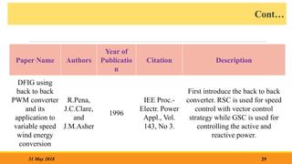
[13] A. Gaillard, P. Poure, and S. Saadate, “Active filtering capability of WECS With DFIG for
grid power quality improvement”, Proc. IEEE Int. Symp. Ind. Electron., June.30, 2008, pp.2365-
2370.
[14] M. Boutoubat, L. Mokrani, and M. Machmoum, “Control of a wind energy conversion system
equipped by a DFIG for active power generation and power quality improvement,” IEEE Renew.
Energy, vol. 50, pp. 378-386, Feb 2013.
79
31 May 2018](https://image.slidesharecdn.com/workproposalpresentation-240108103735-448ff1c2/85/work-proposal-presentation-pptx-thesis-new-79-320.jpg)
![Cont…
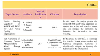
[15] E. Tremblay, A Chandra and P. J. Lagace, “Grid-side converter control of DFIG wind turbines
to enhance power quality of distribution network,” 2006. IEEE PES General Meeting, pp. 6.
[16] N.K.S.Naidu, B.Singh, “Doubly Fed Induction Generator for Wind Energy Conversion
Systems with Integrated Active Filter Capabilities”, IEEE
Trans.Ind.Inform.,Vol.11,no.4,Aug2015,pp.923-933.
[17] A.Merabet, A. A. Tanvir, K. Beddek, “Speed control of sensorless induction generator by the
artificial neural network in wind energy conversion system”, IET Renew. Power Gener., 2016.
[18] S.H.Zak, “System and Control”, NewYork, Oxford University Press, 2003.
[19]N.Govindarajan, D.Raghavan, “Doubly Fed Induction Generator based wind turbine with
Adaptive Neuro Fuzzy Inference system controller”, Asian journal of scientific research, 2014,
vol.7, Iss.1,pp.45-55.
[20]Amit Kumar, D.Giribabu, “Performance improvement of DFIG fed wind energy conversion
system using ANFIS controller”, IEEE,2016, International conference on AEEICB16.
[21] Ahmed A.Zaki Diab, S.A.A.Maksoud, B.E.Elnagli, Denis.A.Kotin, “Performance of doubly
fed induction generator based wind turbine using adaptive neuro-fuzzy inference system”,
IEEE,2016, IFOST-2016, pp.145-149.
80
31 May 2018](https://image.slidesharecdn.com/workproposalpresentation-240108103735-448ff1c2/85/work-proposal-presentation-pptx-thesis-new-80-320.jpg)
![Cont…
[22] V.Yaramasu, B.Wu, P.C.Sen, S.Kouro, and M.Narimani, “High power wind energy
conversion system: State-of-the-Art and Emerging technology”, IEEE, vol.103, issue 5, May 2015,
pp 740-788.
[23]Mohamed R. Amer, Osama A. Mahgoub, and Sherif A. Zaid, “A simple algorithm for SRF
theory with three-phase shunt Active Power Filter”, Journal of engineering and computer science”,
Qassim University,vol.6,no-1,pp.11-32,2013.
[24]D.Bystrov, J.Westin, “Practice Neuro-Fuzzy Logic System-Matlab GUI toolbox”, pdf file
accessed on www.google.com.
[25]Asit Mohanty, Meera Viswavandya, Prakash K. Ray, Sandipan Patra, “Stability analysis and
reactive power compensation issue in a microgrid with DFIG based WECS”, Elsevier,2014,
Electrical Power and Energy Systems 62,pp753-762.
[26]A. M. Eltamaly and A.A. khan, “Investigation of DC link capacitor failures in DFIG based
Wind Energy conversion system”, STM Journals, Trends in Electrical Engineering, 2011,Vol. 1,
iss.1, pp. 12-21.
81
31 May 2018](https://image.slidesharecdn.com/workproposalpresentation-240108103735-448ff1c2/85/work-proposal-presentation-pptx-thesis-new-81-320.jpg)
![Cont…
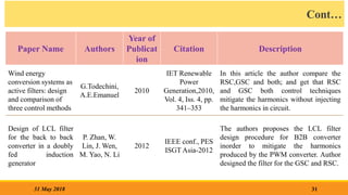
[27] A. M. S. Yunus, A. A. Siada, and M. A. S. Masoum, “Impact of DC link fault on the dynamic
performance of DFIG”,IEEE 2012.
[28] H. A. Sher, K. E. Addoweesh and Y. Khan, “ Effect of short circuited DC link capacitor of an AC-
DC-AC inverter on the performance of induction motor” , Journal of King Saud University-Engineering
Sciences, 2014,28,pp. 199-206.
[29] D.G. Giaourakis and A. N. Safacas, “Effect of short circuit faults in the back to back power
electronic converter and rotor terminals on the operational Behaviour of the Doubly Fed Induction
generator wind energy conversion system”, Machines, 2015, 3, pp.2-26.
[30] P. Zhan, W. Lin, J. Wen, M. Yao, N. Li, “ Design of LCL filter for the back-to-back converter in a
doubly fed induction generator” , IEEE Conf., IEEE PES ISGT ASIA 2012, pp.1 -6.
[31] M. Huang, X.Wang, P.Chiang, F.Blaabjerg, “Design of LLCL filter for grid connected converter to
improve stability and robustness”, Proceed., IEEE Applied Power Electronics Conf. ,2015, pp. 2959-
2966.
[32] M. Huang, F.Blaabjerg, Y.Yongh, W.Weimin, “Step by step design of a high order power filter for
three phase three wire grid connected inverter in renewable energy system” , Proceed. 4th IEEE
Symposium on Power Electron. For DGS,PEDG 2013.
82
31 May 2018](https://image.slidesharecdn.com/workproposalpresentation-240108103735-448ff1c2/85/work-proposal-presentation-pptx-thesis-new-82-320.jpg)
![Cont…
[33]
83
31 May 2018](https://image.slidesharecdn.com/workproposalpresentation-240108103735-448ff1c2/85/work-proposal-presentation-pptx-thesis-new-83-320.jpg)


![SAS Presentation [Autosaved], DFIG in WECS](https://cdn.slidesharecdn.com/ss_thumbnails/saspresentationautosaved-240629104239-2fc00eb2-thumbnail.jpg?width=640&height=640&fit=bounds)


