Rigid – Semi Rigid -Flexible -تصميم بلاطة الديافرام لمقاومة قوى الزلازل -Diaphragm For Seismic Analysis
•
27 likes•4,818 views

There are some circumstances, however, where the rigid diaphragm assumption may not be appropriate: floors with numerous openings, roof diaphragms of metal decking without concrete fill or of plywood sheathing, etc. Long, narrow diaphragms may be considered rigid in one direction but not in the other. For structures with multiple wings, such as L- or C-shaped buildings where the ends of the wings can drift independently of each other, the rigid diaphragm analysis may not be appropriate since it would lock the ends of the wings together, constraining them to move in unison Seismic analysis and design

Recommended
Recommended
More Related Content
What's hot
What's hot (20)
Viewers also liked
Viewers also liked (7)
More from Dr.Youssef Hammida
More from Dr.Youssef Hammida (20)
Recently uploaded
Recently uploaded (20)
Rigid – Semi Rigid -Flexible -تصميم بلاطة الديافرام لمقاومة قوى الزلازل -Diaphragm For Seismic Analysis
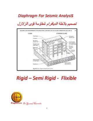
- 1. 1 Dr Youssef Hammida Diaphragm For Seismic Analysis اﻟدﯾﺎﻓرام ﺑﻼطﺔ ﺗﺻﻣﯾمﻟﻣﻘﺎوﻣﺔﻗوىاﻟزﻻزل Rigid – Semi Rigid - Flixible
- 2. 2 The rigid diaphragmاﻟﺻﻠب اﻟدﯾﺎﻓرام is a convenient analytical technique for distributing the lateral forces to the frames and walls; forces are distributed to those elements as a function of their relative stiffnesses and position. Analysis using the rigid diaphragm assumption is generally adequate when the diaphragm in-plane stiffness is high relative to that of the frames. There are some circumstances, however, where the rigid diaphragm assumption may not be appropriate: floors with numerous openings, roof diaphragms of metal decking without concrete fill or of plywood sheathing, etc. Long, narrow diaphragms may be considered rigid in one direction but not in the other. For structures with multiple wings, such as L- or C-shaped buildings where the ends of the wings can drift independently of each other, the rigid diaphragm analysis may not be appropriate since it would lock the ends of the wings together, constraining them to move in unison. In these cases it may be necessary or required to analyze the structure modeled with semi-rigid diaphragms. It is often appropriate to analyze some stories using the rigid diaphragm assumption and other stories using the semi-rigid assumption. اﻟ ﻣن اﻷﻓﻘﯾﺔ اﻟﺣﻣوﻻت ﯾﺣول اﻟذي ھو اﻟﺻﻠب اﻟدﯾﺎﻓرامواﻟزﻻزل رﯾﺎح ﺻﻼﺑﺗﮫ وﻓﻖ ﻛل واﻷﻋﻣدة اﻟﺟدران ﻣن اﻟرأﺳﯾﺔ اﻟﻌﻧﺎﺻر اﻟﻰ ﻛﺑﯾرة ﺻﻼﺑﺗﮫ ﺗﻛون ﻋﻧدﻣﺎ ﺻﻠب اﻟدﯾﺎﻓرام ﻓرض ﯾﻣﻛن اﻟﺗﺻﻣﯾم ﻓﻲ ﺻﻼﺑﺔ ﻣﻊ وﻣﻘﺎرﻧﺗﮭﺎاﻟرأﺳﯾﺔ اﻟﻌﻧﺎﺻر
- 3. 3 ھﯾﺎﻛل ﻣﺑﺎﻧﻲﻣﻊأﺟﻧﺣﺔ،ﻣﺗﻌددةﻣﺛلL-أواﻟﻣﺑﺎﻧﻲﻋﻠﻰﺷﻛلCﺣﯾثﻧﮭﺎﯾﺎتاﻷﺟﻧﺣﺔﯾﻣﻛنأن ﺗﻧﺗﻘلﺑﺷﻛلﻣﺳﺗﻘلﻋنﺑﻌﺿﮭﺎ،اﻟﺑﻌضﻗدﻻﯾﻛونﺗﺣﻠﯾلﺻﻠب دﯾﺎﻓرام اﻟﻣﻧﺎﺳب ھوﻷﻧﮫﺳﯾﻛونﻗﻔلﻟﻧﮭﺎﯾﺎتاﻷﺟﻧﺣﺔ،ﻣﻌﺎوﺗﻘﯾﯾدﻟﮭماﻟﺣرﻛﺔ ﻣن ﺻﻠب ﻏﯾر دﯾﺎﻓرام ﯾﻔﺿل ﻟذﻟك diaphragm can be considered "flexible" if it is constructed of untopped steel decking or wood structural panels and the structural system is steel, concrete or masonry frames or walls, or when the maximum in-plane deflection of the diaphragm under lateral load is more than two times the average drift of the adjacent lateral frames. In contrast, it specifies that a diaphragm can be considered "rigid" if it is a concrete slab or concrete-filled metal deck, with some limitations. Otherwise, the diaphragm must be modeled and analyzed as semi- rigid. It may also be more practical to analyze the diaphragms as semi-rigid and avoid the need to perform the deflection calculations necessary to classify the diaphragms otherwise. It is permissible in any case to model and analyze the diaphragm as semi-rigid.
- 4. 4 اﻟﺳﻘف ﻣﺛل ﻣﺳﻠﺣﺔ ﺧرﺳﺎﻧﺔ ﺑﻼطﺔ ﺗﺣوي ﻻ اﻟﺗﻲ اﻟدﯾﺎﻓراﻣﺎت ﺻﻠﺑﺔ ﻏﯾر اﻋﺗﺑﺎرھﺎ ﯾﻣﻛن اﻟﻔوﻻذي اﻟﺻﺎج اﻟواح ﻣن واﻟﻣﻌدﻧﻲ اﻟﺧﺷﺑﻲ ﻟﻺﻧﺗﻘﺎﻻت اﻟﻼزم اﻟﺣﺳﺎب اﺟراء ﻋن ﻋوﺿﺎ ﺻﻠب ﺷﺑﮫ اﻟدﯾﺎﻓرام ﻓرض ﯾﻣﻛن ﺷﺑﮫ او ﻧﺻف اﻟدﯾﺎﻓرام ﻓرض وﻗﺑول اﻟﺗﺻﻣﯾم ﻣﺑﺎﺷرة وﯾﻣﻛن وﻟو ﺣﺗﻰ ﺻﻠبﺻﻠﺑﺎ ﻛﺎن اﻟدﯾﺎﻓرام" :"Diaphragm اﻟﻌﻧﺎص ﻋﻠﻰ ﯾطﻠﻖاﻟﻣﺳﺗوﯾﺔاﻷﺣﻣﺎل ﺑﻧﻘل ﺗﻘوم اﻟﺗﻲاﻷﻓﻘﯾﺔ واﻟزﻻزل اﻟرﯾﺎح ﻣناﻻﺧرى اﻟﻌﻧﺎﺻر إﻟﻰ ﻣﺳﺗوﯾﮭﺎ ﻓﻲارأﺳﯾﺔﺑﮭﺎ اﻟﻣرﺗﺑطﺔ دﯾﺎﻓراﻣﺎت اﻟﺑﻼطﺎت ﺗﻌﺗﺑر ﺣﯾثﺻﻠﺑﺔاﻟﻘوى ﻋن اﻟﻧﺎﺗﺟﺔ اﻟﺟﺎﻧﺑﯾﺔ اﻷﺣﻣﺎل ﺑﻧﻘل ﺗﻘوم ﻋﻧدﻣﺎ اﻟﻘص وﺣواﺋط ﻛﺎﻻﻋﻣدة اﻟراﺳﯾﺔ اﻟﻌﻧﺎﺻر إﻟﻰ اﻟرﯾﺎح أو اﻟزﻟزاﻟﯾﺔ. ﺻﻼﺑﺗﮫ وﻓﻖ ﻛل اﻟﻌﻧﺎﺻر اﻟﻰ اﻟﻘوى وﺗوزع
- 5. 5 ﯾﻌﺘﻤﺪ ﻓﮭﻮ ﻣﺮن او ﺻﻠﺐ ﻛﺎن ﺳﻮاء اﻟﺪﯾﺎﻓﺮاموﯾﺘﺄﺛﺮ اﻟﺮأﺳﯿﺔ اﻟﻌﻨﺎﺻﺮ ﺑﺼﻼﺑﺔ -اﻟﻤﺴﺎﻧﺪ اﻟﻰ ﺗﻨﺘﻘﻞ اﻷﻓﻘﯿﺔ اﻟﺤﻤﻮﻻت اﻟﻤﺮن اﻟﺪﯾﺎﻓﺮام ﻓﻲ ﻣﻨﺼﻒ ﺑﻄﺮﯾﻘﺔ اﻟﺠﺪرانطﺮﻓﻲ ﻋﻠﻰ اﻟﺒﻼطﺔ ﻣﻦ اﻟﻤﺴﺎﺣﺎت اﻟﻌﺎﻣﻮد ﺣﻤﻮﻟﺔ ﺣﺴﺎب ﺣﺎل ﻓﻲ ﻛﻤﺎ اﻟﺠﺪار
- 6. 6 اﻟﺪﯾﺎﻓﺮام ﻟﺒﻼطﺔ اﻷﻓﻘﻲ اﻻﻧﺘﻘﺎل ﺣﺴﺎب
- 7. 7
- 8. 8 ﺻﻼﺑﺔ وﻓﻖ اﻟﻘﺺ ﻣﻦ اﻟﺠﺪران ﺣﺼﺔ ﺣﺴﺎب ﺻﻠﺐ دﯾﺎﻓﺮام ﻓﻲ اﻟﺠﺪران
- 9. 9
- 10. 10 اﻟﺪﯾﺎﻓﺮام ﺑﻼطﺎت ﺑﯿﻦ اﻟﻘﺎﻋﺪي اﻟﻘﺺ ﻗﻮى اﻧﺘﻘﺎل ﻛﯿﻔﯿﺔ اﻷﺳﻔﻞ اﻟﻰ اﻷﻋﻠﻰ ﻣﻦ
- 11. 11 اﻟﺼﻠﺐ = اﻟﺪﯾﺎﻓﺮام–ﺻﻠﺐ ﺷﺒﮫ-اﻟﻤﺮن
- 12. 12 اﻟﺠﺪران اﻟﻰ اﻟﺪﯾﺎﻓﺮام ﺑﻼطﺔ ﻣﻦ اﻟﻘﺺ ﻗﻮى اﻧﺘﻘﺎل ﻗﺼﯿﺔ وﻣﺠﻤﻌﺎت ﻣﺴﺎرات وﻓﻖ–ﻣﺪﻓﻮﻧﺔ ﻛﻤﺮة
- 13. 13 ﺳﻤﺎﻛﺔ وﻓﻖ اﻟﻜﻮد ﺣﺪدھﺎ اﻟﺪﯾﺎﻓﺮام ﻧﻮع اﺧﺘﯿﺎر اﻟﻤﺎدة وﻧﻮﻋﯿﺔ اﻟﺪﯾﺎﻓﺮام ﺑﻼطﺔ -ﺑﺎﻧﻮاﻋﮭﺎ اﻟﻤﺴﻠﺤﺔ اﻟﺨﺮﺳﺎﻧﺔ ﺑﻼطﺎت ﻓﻜﻞ ﺑﻼطﺎت ﺣﺘﻰاﻟﺼﻨﻊ اﻟﻤﺴﯿﻖ ﻓﻲ اﻟﺘﻐﻄﯿﺔ ﺗﻌﺘﺒﺮRigidﺻﻠﺒﺔ -ﺣﺴﺎب ﯾﺘﻄﻠﺐ اﻟﻜﻮدات وﺑﻌﺾدﯾﺎﻓﺮام اﻧﺘﻘﺎل ﺗﻌﺘﺒﺮ واﻻ ﻣﻌﯿﻨﺔ ﺣﺪود ﺿﻤﻦ اﻟﺴﻘﻒ ﺑﻼطﺔ –semi اﻟﻤﻌﺪﻧﯿﺔ اﻟﺴﺘﯿﻞ واﺳﻘﻒ ﺑﻼطﺎت ﺑﺎﻗﻰ اﻣﺎ اﻟﻌﺎزل واﻟﺼﻨﺪوﯾﺶ اﻟﺼﺎج اﻟﻮاح ﻣﻦ ﻣﺮﻧﺔ ﻓﺘﻌﺘﺒﺮflexible
- 14. 14 اﻟﺪﯾﺎﻓﺮام ﻧﻮع ﺗﺤﺪﯾﺪ ﻧﻘﺼﺪه ﻣﺎﻧﻮع ﻋﻠﻰ ﯾﻌﺘﻤﺪ ﻧﻔﺴﺔ اﻟﺪﯾﺎﻓﺮام وﻣﺎدة -ﻋﻠﻰ ﻓﯾﻌﺗﻣد اﻷﻓﻘﯾﺔ اﻟﻘص ﻗوة ﻣﻘدار ﺗوزﯾﻊ اﻣﺎ اﻟرأﺳﯾﺔ اﻟﻌﻧﺎﺻر وﺻﻼﺑﺎت اﻟدﯾﺎﻓرام ﻧوع in the analysis of multistory buildings subjected to lateral loads, a common assumption is that the floor system undergoes no deformation in its own plan [1, 2]. Building structures are typically designed using the assumption that the floor systems serve as a rigid diaphragm between the vertical elements of the lateral load-resisting system. For the majority of buildings, floor diaphragms offer the most economical and rational method of resisting the lateral forces, since they are ordinarily included in the buildings to support the vertical workloads. It is thus, of the utmost importance, that they must be provided with sufficient in-plane stiffness and strength, together with efficient connections to the vertical structural elements investigation into the Floor Diaphragms Flexibility inReinforced Concrete Structures and Code Provision All the seismic codes generally accept that in most cases the floor diaphragms may be modeled as fully rigid without inplane deformability.
- 15. 15 Even though a rigid floor diaphragm is a good assumption for seismic analysis of the most buildings, several building configurations may exhibit significant flexibility in floor diaphragms. In these configurations, some codes like (EC8, NZS4203, GSC- 2000) set certain qualitative criteria related to the shape of the diaphragm, while some others (2800, UBC-97, SEAOC-90, FEMA-273) set quantitative criteria relating the in-plane deformation of the diaphragm with the average drift of the associated storey
- 16. 16 اﻟﺘﺤﻘﻖﺑﺤﺴﺎب وذﻟﻚ ﺻﻠﺐ ﺷﺒﮫ ام ﺻﻠﺐ اﻟﺪﯾﺎﻓﺮام ﻧﻮع ﻣﻦ اﻟﺮاﺳﻲ اﻟﻌﻨﺼﺮ واﻧﺘﻘﺎل اﻟﺪﯾﺎﻓﺮام اﻧﺘﻘﺎل A. Floor diaphragms shall be classified as either “flexible”, “stiff”, or “rigid”. B. “Flexible” when the maximum lateral deformation of the diaphragm along its length is more than twice the average inter-storey drift of the storey immediately below ( λ ≥ 2 ), C. “rigid” when this lateral deformation of the diaphragm is less than half the average inter-storey drift of the associated storey ( λ < 5.0 ) and D. “stiff” when the diaphragm it is neither flexible nor rigid ( 0. λ <≤ 25 ).
- 17. 17 اﻟﺪﯾﺎﻓﺮام ﺑﻼطﺎت ﻓﻲ ﺗﻌﻤﻞ اﻟﺘﻰ اﻟﻘﺎﻋﺪى اﻟﻘﺺ ﻣﺜﻠﺚ ﻗﻮى ﺣﺴﺎب طﺎﺑﻖ ﻛﻞ ﻓﻲ
- 18. 18 اﻟﺘﺤﻘﯿﻖﻣﻦﻧﻮﻋﯿﺔاﻟﻄﺎﺑﻖ اﻧﺘﻘﺎل اﻟﻰ اﻧﺘﻘﺎﻟﺔ ﻧﺴﺒﺔ ﻣﻘﺪار ﻣﻦ اﻟﺪﯾﺎﻓﺮام
- 19. 19 Eccentricity – For rigid diaphragms, the accidental eccentricity associated with seismic loading is concentrated and applied at the center of mass, whereas for semi-rigid diaphragms, accidental eccentricity is applied to every node for seismic loads. If no diaphragm is assigned eccentricity will not be applied to any node. For wind cases and rigid diaphragm, load is applied at geometric centroid, in case of semi-rigid diaphragm loads are distributed in 10 nodes, so that the summation of these forces with respect to centroid will be equivalent to lateral and torsional wind cases. Reporting forces – In-plane chord, shear, and collector forces are only reported when using semi-rigid diaphragms. ﻓﻲاﻟﻌطﺎﻟﺔ ﻗوى اﻟﺻﻠب اﻟدﯾﺎﻓراماﻟﻛﺗﻠﺔ ﻣرﻛز ﻓﻲ ﺗطﺑﻖ واﻟﺟدران اﻷﻋﻣدة ﻋﻘد ﻓﻲ ﺗطﺑﻖ ﺻﻠب ﻏﯾر اﻟدﯾﺎﻓرام ﺣﺎل ﻓﻲ ﻟﻛن Forces in diaphragms under earthquakes ‘Inertia’ forces – Inertia at a particular floor • ‘Transfer’ forces – Forces develop between primary lateral force resisting structures
- 20. 20 – These forces are often very large. Force distribution in a floor diaphragm = Inertia + Transfer forces Floor plan configuration issues ﺻﻠﺑﯨﺔ ﺷﺑﮫ اﻟﺗﺻﻣﯾم ﻓﻲ ﻗرﺿﮭﺎ ﯾﻘﺿل ﻣﻧﺗظﻣﺔ اﻟﻐﯾر اﻷﺷﻛﺎل دﯾﺎﻓرام اﻟ وﺣرﯾﺔ اﻷﺟﻧﺣﺔ ﺑﯾن اﻟﻔﺻل اوﺣرﻛﺔ ﺻﻠب دﯾﺎﻓرام(rigid diaphragm ): و اﻟﺑﻼطﺔ ﻣﺳﺗوي ﻓﻲ ﺗﺷوه ﯾﺣدث ﻻ وﺑﺎﻟﺗﺎﻟﻲ ﻛﺑﯾرة ﺻﻼﺑﺔ ذات اﻟﺑﻼطﺔ أن أي ﺟﺳﺎﺋﺗﮭﺎ ﻟﻧﺳب ﺗﺑﻌﺎ اﻹﻧﺷﺎﺋﯾﺔ اﻟﻌﻧﺎﺻر ﻋﻠﻰ اﻷﺣﻣﺎل ﺗوزﯾﻊ ﯾﻛون ﺻﻠب ﺷﺑﮫ دﯾﺎﻓرامSimi rigid diaphragm) اﻷﺣﻣﺎل ﺗوزﯾﻊ ﯾﻛون ﻻ وﺑﺎﻟﺗﺎﻟﻲ اﻟﺑﻼطﺔ ﻣﺳﺗوي ﻓﻲ ﺗﺷوه ﯾﺣدث و ﻛﺎﻓﯾﺔ ﻏﯾر اﻟدﯾﺎﻓرام ﺻﻼﺑﺔ أن أي ﺟﺳﺎﺋﺗﮭﺎ ﻟﻧﺳب ﺗﺑﻌﺎ اﻹﻧﺷﺎﺋﯾﺔ اﻟﻌﻧﺎﺻر ﻋﻠﻰ
- 21. 21 .اﻟﻣراﻓﻖ ﻟﻠطﺎﺑﻖ اﻹزاﺣﺔ ﻣﺗوﺳط ﺿﻌﻔﻲ ﻣن أﻛﺑر ﻟﻠدﯾﺎﻓرام اﻷﻋظﻣﻲ اﻟﺟﺎﻧﺑﻲ اﻻﻧﺗﻘﺎل ﯾﻛون ﻋﻧدﻣﺎ اﻹزاﺣﺔ ﺑﻣﻘﺎرﻧﺔ ذﻟك ﺗﺣدﯾد وﯾﻣﻛنﻟﻠدﯾﺎﻓرام اﻟﻣﺳﺎﻓﺔ ﻣﻧﺗﺻف ﻓﻲ ﻟﻠﻧﻘطﺔ اﻷﻓﻘﻲ اﻟﻣﺳﺗوي ﻓﻲ اﻟﻣﺣﺳوﺑﺔ اﻟرأﺳﯾﺔ ﻟﻠﻌﻧﺎﺻر اﻟدور إزاﺣﺔ ﻣﻊ ،اﻟﺟﺎﻧﺑﻲ اﻟﺣﻣل ﺑﺗﺄﺛﯾر ،ذاﺗﮫ اﻟﺑﻼطﺔ ﺻﻼﺑﺔ ﺗﻧﺧﻔض وﺑﺎﻟﺗﺎﻟﻲ اﻟدﯾﺎﻓرام أﺟزاء ﺑﻌض ﻓﻲ اﻧﻘطﺎﻋﺎت وﺟود ﯾﻛون ﻋﻧدﻣﺎ. دون ﺳﺗﯾل اﻟﻣﻌدﻧﯾﺔ واﻟﺑﻼطﺎت ﻟﻠﺳﻘوف ھو اﻟﻣرن اﻟدﯾﺎﻓرامﺧﺷﺑﯾﺔ او ﺧرﺳﺎﻧﺔ ﺑﻼطﺔ اﻟﺮأﺳﯿﺔ اﻟﻤﻘﺎوﻣﺔ اﻟﻌﻨﺎﺻﺮ إﻟﻰ اﻟﺠﺎﻧﺒﯿﺔ اﻟﻘﻮى ﺑﺘﻮزﻳﻊ ﻳﻘﻮم اﻟﺼﻠﺐ اﻟﺪﻳﺎﻓﺮام ﻻ )أي اﻟﺠﺎﻧﺒﯿﺔ اﻟﻘﻮى ﺗﺄﺛﯿﺮ ﺗﺤﺖ ﻳﻨﺤﻨﻲ ﻻ وھﻮ اﻟﻌﻨﺎﺻﺮ ھﺬه ﺻﻼﺑﺔ ﺑﺤﺴﺐ .اﻟﺮأﺳﯿﺔ اﻟﻤﻘﺎوﻣﺔ اﻟﻌﻨﺎﺻﺮ إﻟﻰ اﻟﻔﺘﻞ ﻧﻘﻞ ﻋﻠﻰ ﻗﺎدر ھﻮ ﻟﺬﻟﻚ (ﻳﺘﺸﻮه ﻋﻨﺼﺮ ﻓﮫﻮ اﻟﻠﯿﻦ اﻟﺪﻳﺎﻓﺮام أﻣﺎ،اﻟﺠﺎﻧﺒﯿﺔ اﻟﻘﻮى ﺗﺄﺛﯿﺮ ﺗﺤﺖ ﻳﻨﺤﻨﻲ ،ﻧﺤﯿﻒ إﻧﺸﺎﺋﻲ ﻋﻠﻰ وﻳﻌﺘﻤﺪ ،اﻟﺮأﺳﯿﺔ اﻟﻤﻘﺎوﻣﺔ اﻟﻌﻨﺎﺻﺮ إﻟﻰ اﻟﻔﺘﻞ ﻧﻘﻞ ﻋﻠﻰ ﻗﺎدر ﻏﯿﺮ ھﻮ ﻟﺬﻟﻚ اﻟﻌﻨﺎﺻﺮ إﻟﻰ اﻟﺠﺎﻧﺒﯿﺔ اﻟﻘﻮى ﻳﻮزع وﻻ ،ﺗﺸﻮھﺎﺗﻪ ﻣﻦ ﻟﻠﺤﺪ اﻟﻌﻨﺎﺻﺮ ھﺬه ﺻﻼﺑﺔ ﺗﺤﻤﻠﮫﺎ اﻟﺘﻲ اﻟﻤﺴﺎﺣﺔ ﻧﺴﺒﺔ ﺑﺤﺴﺐ وإﻧﻤﺎ ،ﺻﻼﺑﺘﮫﺎ ﺑﺤﺴﺐ اﻟﺮأﺳﯿﺔ اﻟﻤﻘﺎوﻣﺔ اﻟﻌﻨﺎﺻﺮ ھﺬه. ﻓﺘﻌﺘﺒﺮان واﻟﺨﺸﺒﯿﺔ اﻟﺨﻔﯿﻔﺔ اﻟﻔﻮﻻذﻳﺔ أﻣﺎ ﺻﻠﺐ دﻳﺎﻓﺮام اﻟﺨﺮﺳﺎﻧﯿﺔ اﻟﺒﻼطﺔ ﺗﻌﺘﺒﺮ .ﻟﯿﻦ دﻳﺎﻓﺮام ﺗﻌﺮﺿﻪ ﻋﻨﺪ ﻳﺘﺸﻮه ﻻ أﻧﻪ ﻳﻌﻨﻲ ﻓﮫﺬا اﻟﺼﻠﺐ اﻟﺴﻘﻒ دﻳﺎﻓﺮام ھﻮ اﻟﻤﻄﻠﻮب أن وﺑﻤﺎ اﻟﻤﻘﺎوﻣﺔ اﻟﻌﻨﺎﺻﺮ إﻟﻰ ًأﻳﻀﺎ اﻟﻔﺘﻞ ﺑﻨﻘﻞ ﻳﻘﻮم ﻓﺈﻧﻪ ﻳﺘﺸﻮه ﻻ أﻧﻪ وﺑﻤﺎ ،ﺟﺎﻧﺒﯿﺔ ﻟﻘﻮة
- 22. 22 ﻓﺗل ﺗواﺟد ﻓﻲ اﻟﺻﻠب اﻟدﯾﺎﻓرام ودوران اﻧﺗﻘﺎل–ﺗورﺷن اﻟﻘﺻﯾﺔ ﻟﻠﺟدران واﻟﺻﻼﺑﺔ اﻟﻛﺗﻠﺔ ﻣرﻛز ﺑﯾن ﻻﻣرﻛزﯾﺔ
- 23. 23 ا واﻟﻣﺻﺎﻋد واﻟﺳﻼم اﻟﻔﺗﺣﺎت وﺗواﺟد ﻣﻔﺿﻠﺔ ﻏﯾر اﺷﻛﺎل ﺗﺟﻧﺑﮭﺎ وﯾﻔﺿل اﻟدﯾﺎﻓراﻣﺎت ﻓﻲ
- 24. 24 اﻟدﯾﺎﻓرام ﺑﻼطﺎت واﻧواع اﺷﻛﺎل
- 25. 25 Structural Behaviour of Diaphragms ﻛﯾﻔﯾﺔواﻟﺟدرا اﻟﻛور اﻟﻰ اﻷﻓﻘﯾﺔ اﻟﻘوى وﻧﻘل اﻟدﯾﺎﻓرام ﻋﻣلن Beam Analogy اﻟﻌﻣﯾﻘﺔ واﻟﻛﻣرة اﻟﺟﺎﺋزي اﻟﻌﻣل- deep beaam اﻟرأﺳﯾﺔ اﻟﻌﻧﺎﺻر ﻋﻠﻰ ﻣﺳﻧود ﻋﻣﯾﻖ ﻛﺟﺎﺋز اﻟﺑﻼطﺔ ﺗﻌﻣل ﻗص وﻗوى اﻧﺣﻧﺎء ﻋزوم ﻓﯾﮭﺎ وﺗﺗوﻟد واﻷﻋﻣدة واﻟﺟدران اﻟﻛور ﻣن ﺿﺎﻏطﺔ ﺷﺎدة ﻣﺣورﯾﺔ وﻗوىﺣﺎﻟﮫ ﻟﻛل اﻟﻼزم اﻟﺗﺳﻠﯾﺢ اﯾﺟﺎد وﯾﺟب اﻟﺷﺎﻗوﻟﯾﺔ اﻟﺣﻣوﻻت ﺗﺳﻠﯾﺢ اﻟﻰ واﺿﺎﻓﺗﮫ
- 26. 26
- 27. 27
- 28. 28
- 29. 29 The code is allowing the designer to consider Rigid Diaphragm for reinforced concrete monolithic slab-beam floors or those consisting of prefabricated/ precast elements with topping reinforced screed. The following condition has been proposed to evaluate the flexibility of a diaphragm. ﻟﻧﻘل ﻣﺟﻣﻌﺎت ﻛﻠﯾﻛﺗور ﻣدﻓوﻧﺔ ﻛﻣرات ﺗﺻﻣﯾماﻟﺟدار ﺣﺻﺔ اﻟﺟدار اﻟﻰ اﻟﺑﻼطﺔ ﻣن اﻟﻘص ﻣن
- 30. 30 اﻟﻘص ﻗوى ﺗوزﯾﻊ وﻗﯾﻣﺔ ﻧوﻋﮫ وﻓﻖ اﻟدﯾﺎﻓرام اﻧﺗﻘﺎل اﻟدﯾﺎﻓرام ﺻﻼﺑﺔ وﻓﻖ اﻟﺟدران ﻋﻠﻰ
- 31. 31 ﺑاﻻﺣﻣﺎل ﺗﺣت اﻟﺑﻼطﮫ ﻟﺗﺻﻣﯾم ﺎﻻﺿﺎﻓﮫواﻟﻣﯾﺗﺔ اﻟﺣﯾﺔ اﻟﺷﺎﻗوﻟﯾﺔ ﻣن اﻟﺗﺣﻘﻖ ﻣن ﻻﺑداﻟﺿﻐط و اﻟﺷد ﻗوه ﻣﻘداراﻟﻘص وﻗوى ﻓﻲ اﻟﻣﺗوﻟدهdiaphragmﻣﻘدار ﺣﺳﺎب واﻟﻼزم اﻟﺗﺳﻠﯾﺢ اﻟﻘو ھذه ﯾﻘﺎوم اﻟذيى
- 32. 32
- 33. 33
- 34. 34 ﻋﻣﯾﻖ ﻛﺟﺎﺋز اﻟدﯾﺎﻓرام ﺑﻼطﺔ ﺗﺻﻣﯾم اﻟﻘﺎطﻊ واﻟﺟﮭد اﻟﻌزم ﻣﺧطط اﯾﺟﺎد اﻻﻧﻌطﺎف ﺗﺳﻠﯾﺢ اﯾﺟﺎداﻟﻌرﺿﻲ اﻟﻘص وﺗﺳﻠﯾﺢ اﻷطراف ﻋﻧد ﻓﻲ اﻟﻌﻣل ﻛﻣﺎاﻟﻛﻣرات اﻷﻓﻘﻲ اﻟﻔﻌل رد ﻟﻘﯾﻣﺔ اﻟﻣﺳﺎوﯾﺔ اﻟﺷﺎدة اﻟﻘوى ﻣن ﻛﻠﯾﻛﺗور ﺗﺳﻠﯾﺢ ﺛم اﻟﺟدار ﻣﺳﺎﻧد ﻋﻧد
- 35. 35 TYPES OF DIAPHRAGM Rigid Diaphragms A diaphragm may be considered rigid when its midpoint displacement, under lateral load, is less than twice the average displacements at its ends. Rigid diaphragm distributes the horizontal forces to the vertical resisting elements in direct proportion to the relative rigidities. It is based on the assumption that the diaphragm does not deform itself and will cause each vertical element to deflect the same amount. Rigid diaphragms capable of transferring torsional and shear deflections and forces are also based on the assumption that the diaphragm and shear walls undergo rigid body rotation and this produces additional shear forces in the shear wall. Rigid diaphragms consist of reinforced concrete diaphragms, precast concrete diaphragms, and composite steel deck.
- 36. 36 FLEXIBLE DIAPHRAM. Flexible diaphragms — Roofs or floors including, but not necessarily limited to, those sheathed with plywood, wood decking, or metal decks without structural concrete topping slabs. Metal decks with lightweight fill may or may not be flexible. Diaphragms are considered flexible when the maximum lateral deformation of the diaphragm is more than two times the average story drift of the associated story. This may be determined by comparing the computed midpoint in-plane deflection of the diaphragm itself under lateral load with the drift to adjoining vertical elements under tributary lateral load. A diaphragm is considered flexible, when the midpoint displacement, under lateral load, exceeds twice the average displacement of the end supports. It is assumed here that the relative stiffness of these non-yielding end supports is very great compared to that of the diaphragm. Therefore, diaphragms are often designed as simple beams between end supports, and distribution of the lateral forces to the vertical resisting elements on a tributary width, rather than relative stiffness. Flexible diaphragm is not considered to be capable of distributing torsional and rotational forces. Flexible diaphragms consist of diagonally sheated wood diaphragms, sheathed diaphragms etc. The rigidity of the diaphragms is classified into two groups on relative flexibility: rigid and flexible diaphragm.
- 37. 37
- 38. 38
- 39. 39
- 40. 40
- 41. 41
- 42. 42 The components at the diaphragm boundary acting in tension and compression are known as the tension chord and the compression chord, respectively.
- 43. 43 If the diaphragm moment is resisted by tension and compression chords at the boundaries of the diaphragm as shown in Figure 3-1a, then equilibrium requires that the diaphragm shear be distributed uniformly along the depth of the diaphragm as shown in Figure 3-1c. Tension and compression elements called collectors are required to “collect” this shear and transmit it to the walls A collector can transmit all its forces into the ends of the walls as shown on the right side of Figure 3-2a, or if the forces and resulting congestion are beyond practical
- 44. 44 limits, the collector can be spread into the adjacent slab as shown on the left side of Figure 3-2a. Figure 3-3. As used in this Guide, a collector is an element that takes distributed load from the diaphragm and delivers it to a vertical element, whereas a distributor takes force from a vertical element and distributes it into the diaphragm. دﯾﺎﻓرام ﺗﺄﻣﯾنﺻﻠباﻷﻗﺑﯾﺔ طﺎﺑﻖ ﺳﻘف ﻓﻲ ﻣدﻓوﻧﺔ وﻛﻣرات اﻟﺑدرواﻟﺑدروم ﺟدران اﻟﻰ اﻟﻘص ﻗوى ﻟﺗﺣوﯾل م-اﻷﻗﺑﯾﺔ
- 45. 45 In addition, the inclined ramps can act as unintended diagonal braces that interrupt intended framing action of the vertical elements and result in considerable axial load in the diaphragm. Expansion joints can relieve this action if provided at every level.
- 46. 46 ورﻣب اﻟﺳﻼﻟم ﺑﻼطﺎت ﺗواﺟد ﺣﺎل ﻓﻲاﻟﺳﯾﺎرات اﻟﺿﻐط ﻗوى ﻋﻠﻰ اﻟدﯾﺎﻓرام ﺑﻼطﺔ ﺗﺻﻣﯾم ﯾﺟب اﻷﻓﻘﻲ اﻟﺳﻘف ﻣﻊ اﻟﻣﺎﺋﻠﺔ اﻟﺑﻼطﺔ اﺗﺻﺎل ﻋﻧد
- 47. 47 ﻓﻲاﻟدﯾﺎﻓرام ﺑﻼطﺔ ﻓﻲ ﻛﺑﯾرة ﻓﺗﺣﺎت ﺗواﺟد ﺣﺎل اﻟﺷﺎدة اﻟﻘوى ﻋﻠﻰ اﻟﻔﺗﺣﺎت ﺟواﻧب ﺗﺻﻣﯾم ﻓﯾﺟب اﻟﺿﺎﻏطﺔ
- 48. 48 ﻛﺳرات وﯾﺣوي ﻣﻧﺗظم ﻏﯾر اﻟدﯾﺎﻓرام ﺑﻼطﺔ ﺷﻛل ﺣﺎل ﻓﻲ ﻛذﻟك رﺟوﻋﺎت اواﻟﻣﺟﻣﻊ وﺗﺳﻠﯾﺢ ﻣدﻓوﻧﺔ ﻛﻣرات وﺿﻊ ﯾﺟب-ﻛﻠﯾﻛﺗور
- 49. 49 داﺋﻣﺎ ھﻲ اﻟزﻻزل او اﻟرﯾﺎح ﻣن اﻷﻓﻘﯾﺔ اﻟﻘوى اﻟدﯾﺎﻓرام ﺑﻼطﺔ ﻓﻲ ﺑﺎﻧﺗظﺎم وﻣوزﻋﺔ ﻣوﺟودة
- 50. 50 واﻧﺗﻘﺎﻟﮭﺎ اﻟزﻻزل او اﻟرﯾﺎح ﻗوى ﺗوزع اﻟﺳﻔﻠﻲ اﻟدﯾﺎﻓرام ﺑﻼطﺎت اﻟﻰ
- 51. 51 ﺟﺎﺋز ﻣﺛل اﻟدﯾﺎﻓرام ﺑﻼطﺔ ﺗﺻﯾم-ﻋﻣﯾﻘﺔ ﻛﻣرة واﯾﺟﺎدواﻟﻘص اﻟﻌزم ﻣن اﻟﻼزم اﻟﺗﺳﻠﯾﺢ اﻟﺷﺎﻗوﻟﻲ اﻟﺗﺳﻠﯾﺢ ﻣﻘطﻊ اﻟﻰ واﺿﺎﻓﺗﮫ
- 52. 52
- 53. 53 ﻣﺳﺗﻣرة ﻣرﻧﺔ ﻣﺳﺎﻧد ﻋﻠﻰ ﻋﻣﯾﻘﺔ ﻛﻣرة ﯾﻘﺎﯾﻠﮫ اﻟﻣرن اﻟﻣﺳﺗﻣر اﻟدﯾﺎﻓرام
- 54. 54 Horizontal Diaphragms of Complex shape
- 55. 55
- 56. 56
- 57. 57 – اﻣرﯾﻛﻲ ﻛود diaphragm ACI 318 -14
- 58. 58
- 59. 59
- 60. 60
- 61. 61
- 62. 62 What is the center of rigidity for a semi-rigid diaphragm? Answer: Center of rigidity is only applicable to rigid diaphragms because in-plane slab deformation is variable across laterally loaded semi-rigid diaphragms. During computation, an arbitrary coordinate is selected and loaded, then center of rigidity is derived, as a function of stiffness, according to the displacement at this specific poin ﻟﻠﻛود اﻟﻣواﻓﻖ اﻟﺳوري اﻟﻛوداﻷﻣرﯾﻛﻲ-ASCE 2009
- 64. 64
- 65. 65
- 66. 66
- 67. 67
- 69. 69 Large diameter diaphragm and collector reinforcing bars are commonly spliced using mechanical couplers. Because lap splices of No. 14 bars or larger are prohibited by ACI 318,mechanical couplers are required. Location of Construction Joints Construction joints create weakened planes within a diaphragm. They can also impact development and splices of reinforcement. Shear-friction reinforcement can be provided across construction joints if necessary to maintain continuity of the diaphragm in shear. The impacts to the continuity and development of chord and collector reinforcement at construction joints should also be understood
- 70. 70 seismic Design of Composite Steel Deck and Concrete- filled Diaphragms Flexibility of the diaphragm material. Among the usual building materials, wood or steel decking without concrete are the most flexible. Aspect ratio (length/width) of the diaphragm. The greater the length/width ratio of the diaphragm, the greater the lateral distortions may be. In general, diaphragms with aspect ratios greater than 5 may be considered flexible. Stiffness of the vertical structure. The flexibility of the diaphragm should also be judged in accordance with the distribution of rigid vertical elements in the plan. In the extreme case of a diaphragm in which llelements are of equal stiffness, better performance is expected than when there are major differences in this respect.
- 71. 71 Openings in the diaphragm. Large openings in the diaphragm for purposes of illumination, ventilation, and visual connections between stories cause flexible areas that impede the rigid assembly of the vertical structures.
- 72. 72
- 73. 73
- 74. 74
- 75. 75
- 76. 76
- 77. 77
- 78. 78 Shear Transfer The strength of the diaphragm deck determined for the field of the diaphragm must be adequately transferred to the perimeter framing members if that strength is to be utilized. A variety of fasteners can be utilized to accomplish this load transfer. These include arc-spot (or puddle) welds, self-tapping/self drilling screws, powder-actuated fasteners, and steel headedstud anchors. Additionally, the side seam fastening can be accomplished using welds, screws, or crimping, either traditional “button-punching” or proprietary seaming. As has already been mentioned, the side seam fastening has little influence on composite deck diaphragm strength. DESING EXAMPLE
- 79. 79
- 80. 80
- 81. 81
- 82. 82
- 83. 83 Diaphragm forces- اﯾﺗﺎب ﺑرﻧﺎﻣﺞ
- 84. 84
- 85. 85
- 86. 86
- 87. 87