

Recommended
More Related Content
What's hot
What's hot (20)
Similar to Helical gears formulas
Similar to Helical gears formulas (20)
More from yared seifu
Recently uploaded
Recently uploaded (20)
Helical gears formulas
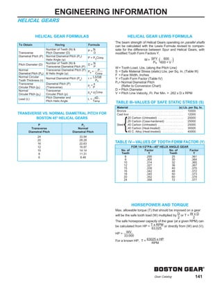
- 1. ® Gear Catalog 141 ENGINEERING INFORMATION HELICAL GEARS HELICAL GEAR FORMULAS TRANSVERSE VS. NORMAL DIAMETRAL PITCH FOR BOSTON 45° HELICAL GEARS HELICAL GEAR LEWIS FORMULA The beam strength of Helical Gears operating on parallel shafts can be calculated with the Lewis Formula revised to compen- sate for the difference between Spur and Helical Gears, with modified Tooth Form Factors Y. W= Tooth Load, Lbs. (along the Pitch Line) S = Safe Material Stress (static) Lbs. per Sq. In. (Table III) F = Face Width, Inches Y =Tooth Form Factor (Table IV) PN= Normal Diametral Pitch (Refer to Conversion Chart) D = Pitch Diameter V = Pitch Line Velocity, Ft. Per Min. = .262 x D x RPM HORSEPOWER AND TORQUE Max. allowable torque (T) that should be imposed on a gear will be the safe tooth load (W) multiplied by D or T = W x D 2 2 The safe horsepower capacity of the gear (at a given RPM) can be calculated from HP = T x RPM or directly from (W) and (V); 63,025 HP = WV 33,000 For a known HP, T = 63025 x HP RPM W= SFY PN 600 600 + V To Obtain Having Formula Number of Teeth (N) & P = N Transverse Pitch Diameter (D) D Diametral Pitch (P) Normal Diametral Pitch (Pn) P = PNCosψ Helix Angle (ψ) Pitch Diameter (D) Number of Teeth (N) & D = N Transverse Diametral Pitch (P) P Normal Transverse Diametral Pitch (P) PN = P Diametral Pitch (PN) & Helix Angle (ψ) Cosψ Normal Circular Normal Diametral Pitch (PN ) τ = 1.5708 Tooth Thickness (τ) PN Transverse Diametral Pitch (P) p t = π Circular Pitch (pt) (Transverse) P Normal Transverse pn = pt Cosψ Circular Pitch (pn) Circular Pitch (p) Lead (L) Pitch Diameter and L = πD Pitch Helix Angle Tanψ P PN Transverse Normal Diametral Pitch Diametral Pitch 24 33.94 20 28.28 16 22.63 12 16.97 10 14.14 8 11.31 6 8.48 TABLE III–VALUES OF SAFE STATIC STRESS (S) Material (s) Lb. per Sq. In. Bronze . . . . . . . . . . . . . . . . . . . . . . . . . . . . . . . . . . . 10000 Cast Iron . . . . . . . . . . . . . . . . . . . . . . . . . . . . . . . . . 12000 .20 Carbon (Untreated) . . . . . . . . . . . . . . . . 20000 .20 Carbon (Case-hardened) . . . . . . . . . . . 25000 Steel .40 Carbon (Untreated) . . . . . . . . . . . . . . . . 25000 .40 Carbon (Heat-treated) . . . . . . . . . . . . . . 30000 .40 C. Alloy (Heat-treated) . . . . . . . . . . . . . 40000 TABLE IV—VALUES OF TOOTH FORM FACTOR (Y) FOR 14-1/2°PA—45° HELIX ANGLE GEAR No. of Factor No. of Factor Teeth Y Teeth Y 8 .295 25 .361 9 .305 30 .364 10 .314 32 .365 12 .327 36 .367 15 .339 40 .370 16 .342 48 .372 18 .345 50 .373 20 .352 60 .374 24 .358 72 .377 {