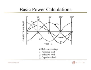

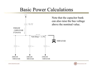
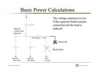
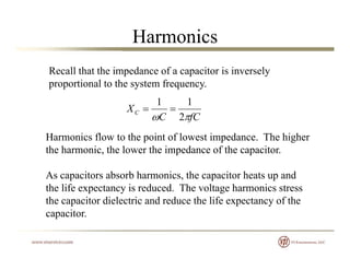
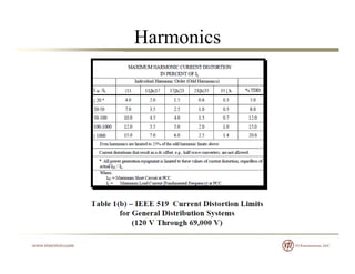
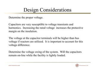
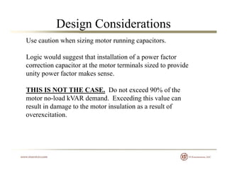
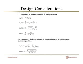
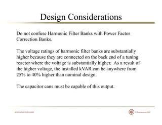
![Basic Power Calculations
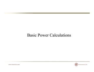
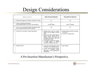
Power Factor [ PF ] = Cos = P / S
S (kVA)
Q (kVAR)
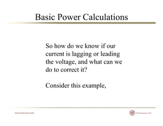
P (W)
Power Triangle
The relationship between S, P, and Q. This figure represents a lagging power
factor. If Q is negative, leading power factor.
g](https://image.slidesharecdn.com/2011cedcapacitors-150502230214-conversion-gate01/85/capacitors-13-320.jpg)
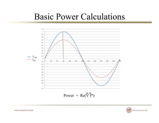
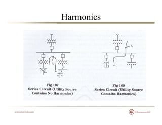
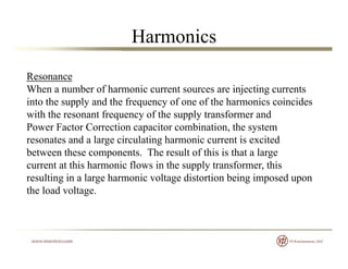
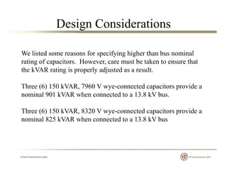
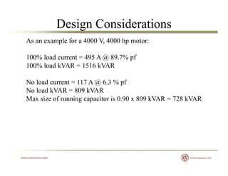
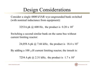
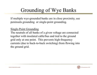
![Basic Power Calculations
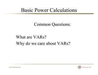
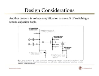
Power Factor [ PF ] = Cos = P / S0.85 lag
S (kVA)
g
Q (kVAR)3400 kVAR
31.8 deg
P (W)
Power Triangle
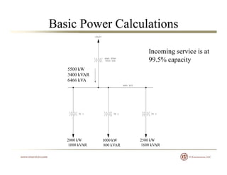
5500 kW
g
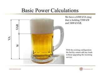
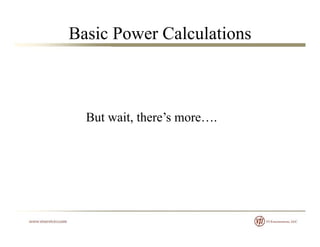
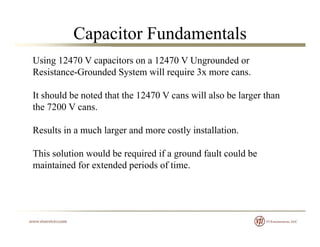
Even though our facility require only 5500 kW to perform Real Work, our
incoming service must be sized for 6466 kVA.](https://image.slidesharecdn.com/2011cedcapacitors-150502230214-conversion-gate01/85/capacitors-16-320.jpg)
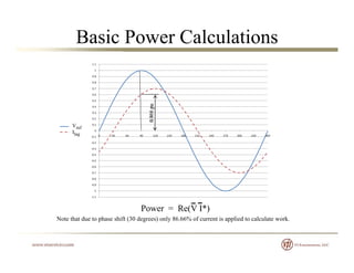
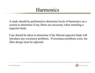
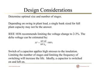
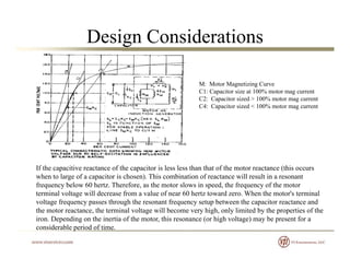
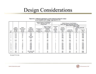
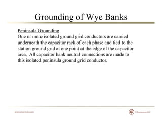
![Basic Power Calculations
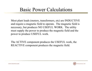
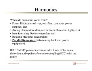
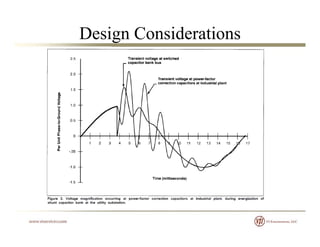
Power Factor [ PF ] = Cos = P / S1.0 unity
S (kVA)
y
Q (kVAR)0 kVAR
0 deg
P (W)
Power Triangle
5500 kW
g
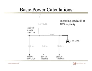
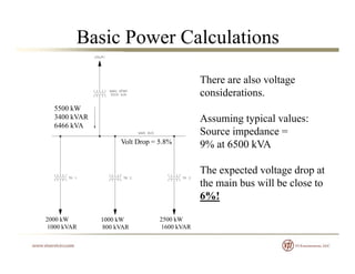
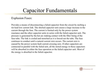
The cap bank is providing 3400 kVAR, so our service is now providing only
5500 kVA (reduction from 6466 kVA.](https://image.slidesharecdn.com/2011cedcapacitors-150502230214-conversion-gate01/85/capacitors-19-320.jpg)
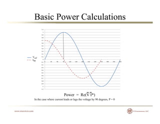
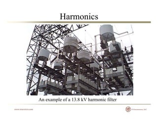
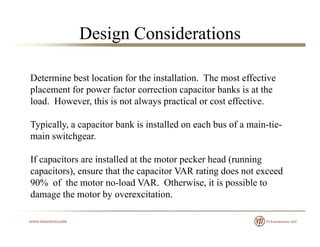
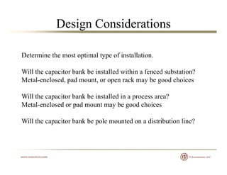
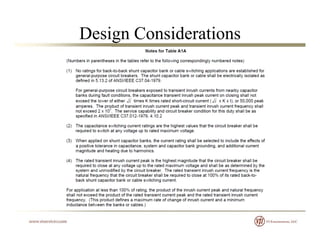
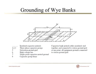
![Basic Power Calculations
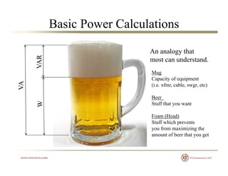
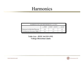
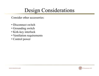
1,500 kVA
COS [ ] = 0.67
COS [ ] = 0.95
Q2 = Q1 + Qc Q1 = 1,118 kVAR
1 000 kW
1,053 kVA
Q2 = 330 kVAR 1,000 kWQ
Qc = 788 kVAR
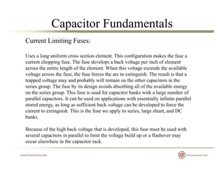
Required Apparent Power
Before and After
Adding a Power Capacitor Bank
An example of how to calculate the size of a cap bank based on a target power factor](https://image.slidesharecdn.com/2011cedcapacitors-150502230214-conversion-gate01/85/capacitors-20-320.jpg)
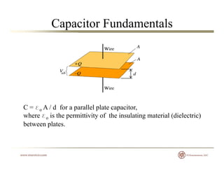
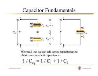
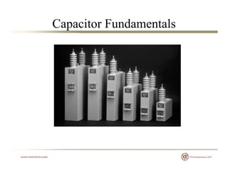
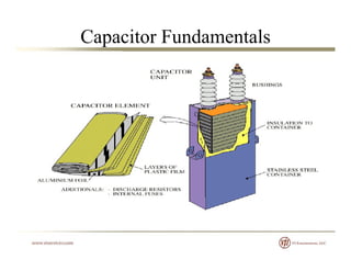
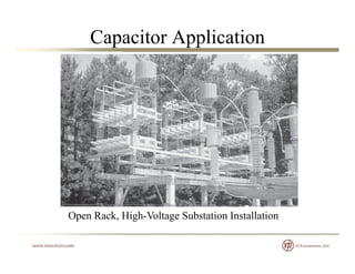
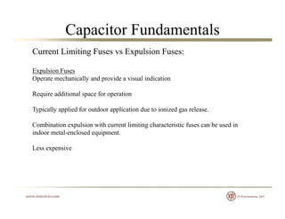
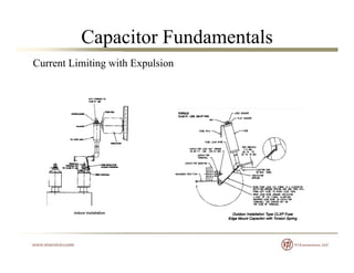
![Capacitor Fundamentals
1000*
][
][
2
kVV
kVARS 000
][
][
Z
kVS
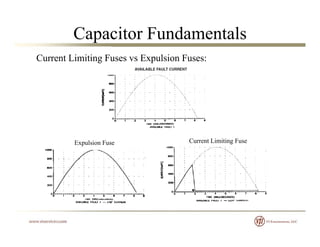
Example:Example:
The capacitance of a capacitor is 6.22 F and the
nameplate voltage is 8000 V. Calculate the power rating.
][7.426
)1022.6)(60)(14.3(2
1
6
x
XC
][150000,1
7.426
)8( 2
kVARS ](https://image.slidesharecdn.com/2011cedcapacitors-150502230214-conversion-gate01/85/capacitors-33-320.jpg)
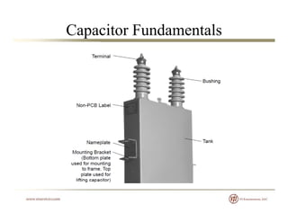
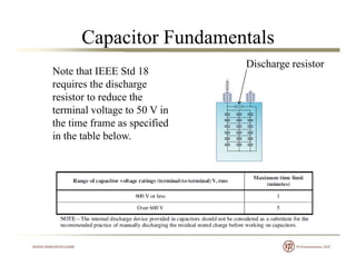
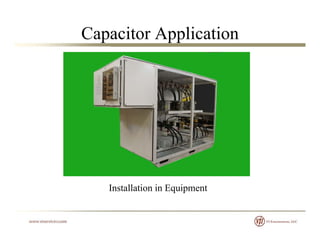
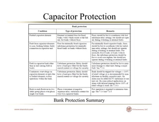
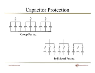
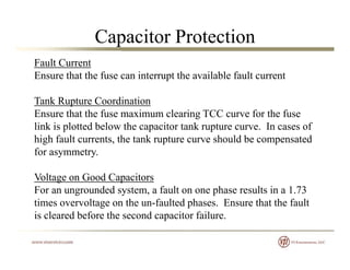
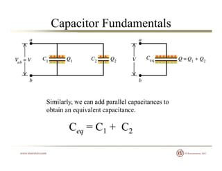
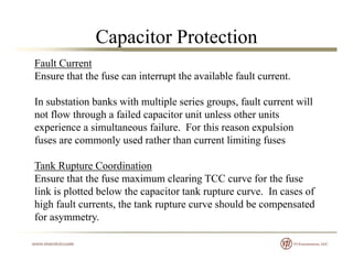
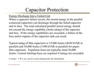
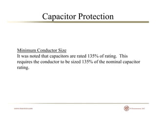
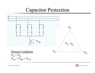
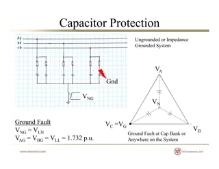
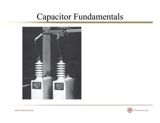
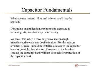
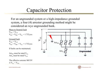
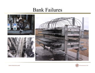
![Capacitor Protection
Problems with Fusing of Small Ungrounded Banks
Consider a 12.47 kV, 1500 kVAR cap bank made of three (3)
500 kVAR i l h i500 kVAR single-phase units.
FuseAAA
kV
kVAR
][100][1045.144.69][44.69
][47.123
][1500
kV ][47.123
If a capacitor fails, we will expect approximately 3x line current.
It will take a 100 A fuse approximately 500 seconds to clear thispp y
fault (3 x 69.44 A = 208.32 A). The capacitor case will rupture
long before the fuse clears the fault.
The solution is using smaller units (explanation to follow).](https://image.slidesharecdn.com/2011cedcapacitors-150502230214-conversion-gate01/85/capacitors-71-320.jpg)
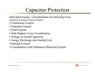
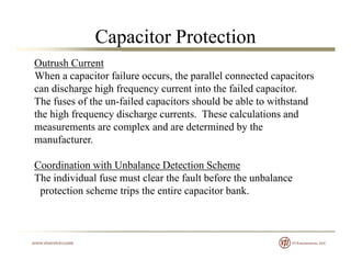
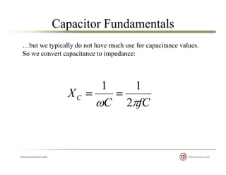
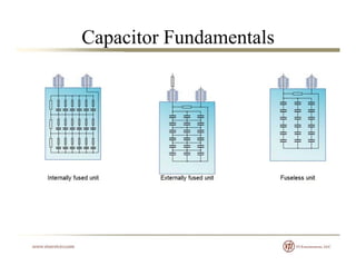
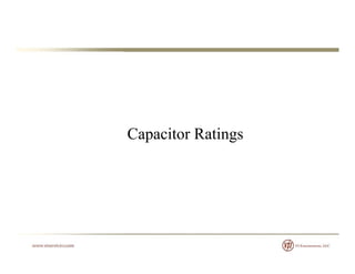
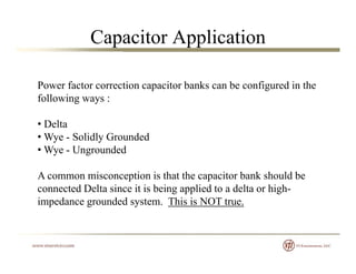
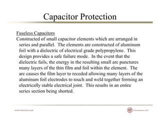
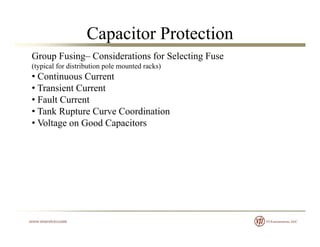
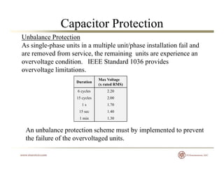
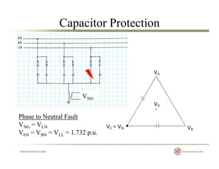
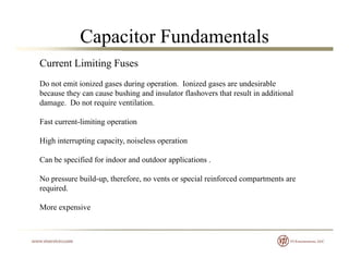
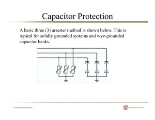
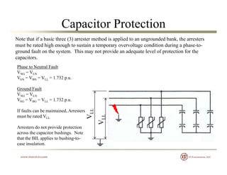
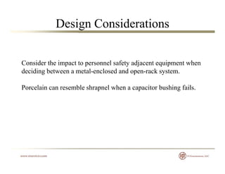
![Capacitor Protection
Recall Problem with Fusing of Small Ungrounded Banks
12.47 kV, 1500 kVAR cap bank made of three (3) 500 kVAR units
FuseAAA
kV
kVAR
][100][1045.144.69][44.69
][47.123
][1500
It will take a 100 A fuse approximately 500 seconds to clear thisIt will take a 100 A fuse approximately 500 seconds to clear this
fault (3 x 69.44 A = 208.32 A). The capacitor case will rupture
long before the fuse clears the fault.
The solution is using smaller units with individual fusing.
Consider five (5) 100 kVAR capacitors per phase, each with a( ) p p p ,
25 A fuse. The clear time for a 25 A fuse @ 208.32 A is below
the published capacitor rupture curve.](https://image.slidesharecdn.com/2011cedcapacitors-150502230214-conversion-gate01/85/capacitors-82-320.jpg)

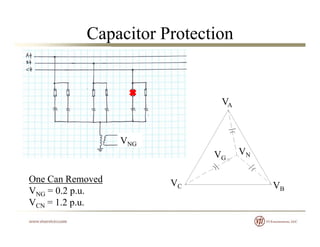
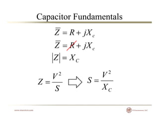
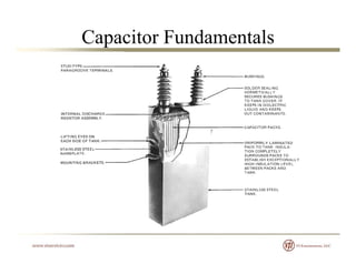
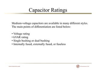
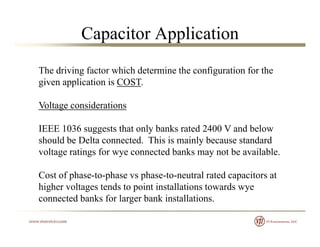
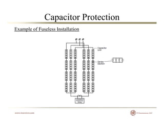
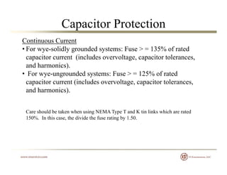
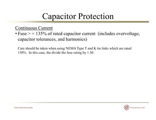
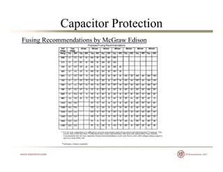
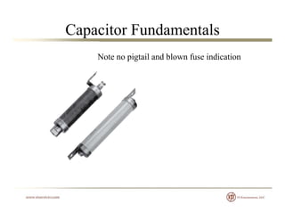
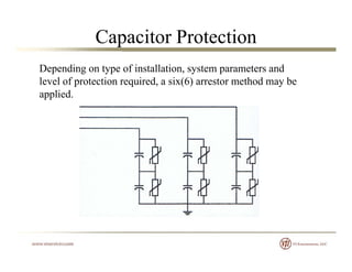
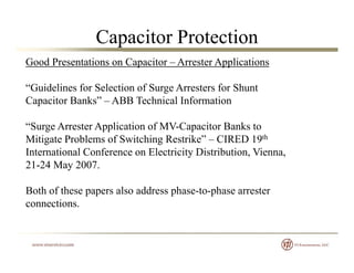
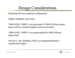
![Capacitor Fundamentals
Recall:
X
V
S
2
CX
This means that a 150 kVAR 12470 V unit applied at 7200 VThis means that a 150 kVAR, 12470 V unit applied at 7200 V
will provide only 50 kVAR.
][50
][150
][12470
][7200
2
2
kVARS
kVAR
V
V
SNEW
][50 kVARSNEW ](https://image.slidesharecdn.com/2011cedcapacitors-150502230214-conversion-gate01/85/capacitors-105-320.jpg)
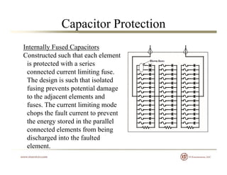
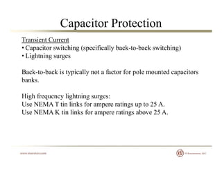
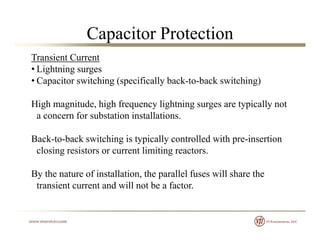
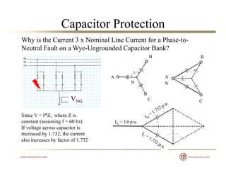
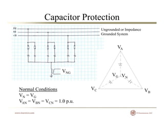
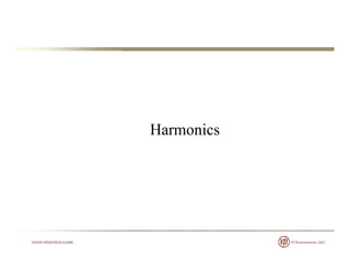
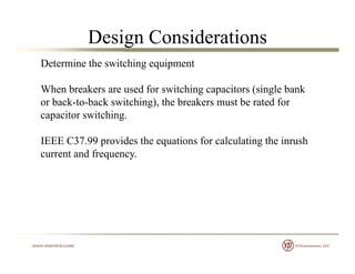
![Capacitor Fundamentals
Perhaps a 150 kVAR or 200 kVAR, 7620 V or 7960 V units
applied at 7200 V would be a better solution.
][150
][7620
][7200
2
2
kVAR
V
V
SNEW ][200
][7620
][7200
2
2
kVAR
V
V
SNEW
][134
OR
kVARSNEW ][178
2
OR
kVARSNEW
][123
][150
][7960
][7200
2
2
kVARS
kVAR
V
V
SNEW
][163
][
][7960
][7200
2
2
kVARS
kVAR
V
V
SNEW
][123 kVARSNEW
Note that the 7620 V unit provides an additional 6%
The 7960 V unit provides an additional 11%
][163 kVARSNEW
The 7960 V unit provides an additional 11%](https://image.slidesharecdn.com/2011cedcapacitors-150502230214-conversion-gate01/85/capacitors-107-320.jpg)

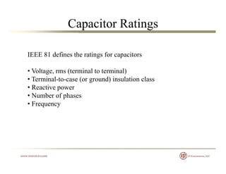
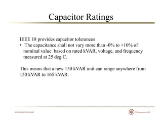
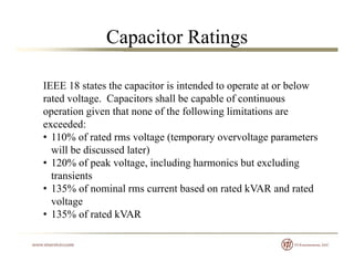
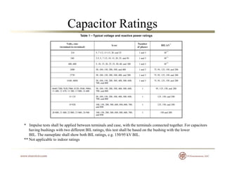
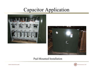
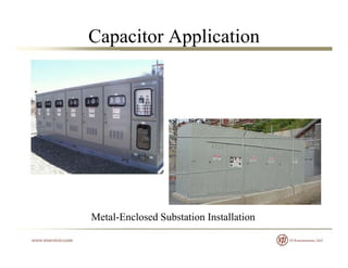
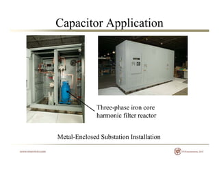
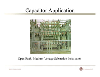
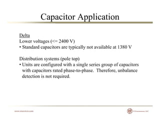
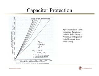
This document provides an overview of capacitors and capacitor fundamentals, ratings, applications, and protection. It discusses basic power calculations involving reactive power (VARs) and power factor. It describes capacitor types, configurations, installation methods, and IEEE standards for ratings and testing. The key points are that capacitors provide reactive power (VARs) to improve power factor; applications include pole-top, pad-mounted, and substation installations; configurations are delta or wye; and ratings are defined by standards.