SlideShare a Scribd company logo
1 of 6
Download to read offline
International Journal of VLSI design & Communication Systems (VLSICS) Vol.3, No.5, October 2012
DOI : 10.5121/vlsic.2012.3513 157
A High-Speed, Low Power Consumption Positive
Edge Triggered D Flip-Flop for High Speed Phase
Frequency Detector in 180 nm CMOS Technology
Prof. R .H. Talwekar, Prof. (Dr.) S.S Limaye
Deptt. Of Electronics and Telecommunication, DIMAT, Raipur.
Deptt. Of Electronics and Telecommunication, JIT, Nagpur.
ur_talwekar@yahoo.com, shyam_limaye@hotmail.com
ABSTRACT
A high speed low power consumption positive edge triggered Delayed (D) flip-flop was designed for
increasing the speed of counter in Phase locked loop, using 180 nm CMOS technology. The designed
counter has been used in the divider chip of the phase locked loop. A divide counter is required in the
feedback loop to increase the VCO frequency above the input reference frequency. The proposed circuit is
faster than conventional circuit as it has fast reset operation. The circuit consumes less power as it
prevents short circuit power consumption. The circuit operates at 1.8V power supply. This work has been
used in the design. of 2.4 GHz CMOS PLL targeting OFDM application. The CMOS based fast D-ff circuit
has designed and simulated by Virtuoso tool of CADENCE spectre
KEYWORDS
Phase locked loop (PLL), Delayed flip-flop (D-ff), Phase frequency detector (PFD),True signal phase clock
(TSPC), Voltage controlled oscillator (VCO), Charge pump (CP), Divider (Div), Low pass filter (LPF).
1. INTRODUCTION
D flip-flop is an important part of the modern digital circuits. Phase locked loop with an excellent
performance is widely studied in recent years. Frequency divider and PFD are indispensable
modules of PLL, which uses D flip-flop as an integral part. Edge Triggered D flip flops are often
implemented in integrated high speed operations using dynamic logic. This means that the digital
output is stored on parasitic device capacitance while the device is not transitioning. This design
of dynamic flip flops also enables simple resetting since the reset operation can be performed by
simply discharging one or more internal nodes. The conventional D flip-flop which uses E-TSPC
logic has higher operating frequencies but it features static power dissipation. However this
causes small increase in power dissipation, since at the frequencies of interest dynamic power
consumption is dominant. In the proposed circuit dynamic power consumption was reduced by
lowering internal switching and speed is increased by shortening input to output path. The paper
is organized as follows. Description of phase locked loop is done in section 2. Circuit diagram of
conventional and proposed D-ff is presented in section 3 and section 4 respectively. In section 5,
simulation results and graphs are presented. Section 6 will draw a conclusion.
International Journal of VLSI design & Communication Systems (VLSICS) Vol.3, No.5, October 2012
158
2. PHASE LOCKED LOOP (PLL)
Phase locked loop is mostly used in wireless communication and data recovery circuits. At
present for above mentioned application a low voltage low area and high performance integrated
circuits are used which complicates the implementation of such type of integrated circuit.
Fig. 2.1 Block diagram of PLL
A PLL is a control system that generates a signal that has a fixed relation to the phase of a
"reference" signal. A phase-locked loop circuit responds to both the frequency and the phase of
the input signals, automatically raising or lowering the frequency of a controlled oscillator until it
is matched to the reference in both frequency and phase. Phase locked loops are built of a
detector, charge pump, low pass filter, voltage-controlled oscillator (VCO) and frequency divider
placed in a negative feedback closed-loop configuration. A phase detector compares two input
signals and produces an error signal which is proportional to their phase difference. The error
signal is then low-pass filtered and used to drive a voltage-controlled oscillator (VCO) which
creates an output frequency. The output frequency is fed through a frequency divider back to the
input of the system, producing a negative feedback loop. If the output frequency drifts, the error
signal will increase, driving the VCO frequency in the opposite direction so as to reduce the error.
Thus the output is locked to the frequency at the other input.
2.1 Phase frequency Detector
A phase frequency detector (PFD), is a device which compares the phase of two input signals and
provides a signal in the form of phase error. It has two inputs which correspond to two different
input signals, usually one from a voltage-controlled oscillator (VCO) and other is a reference
source. It has two outputs which instruct subsequent circuitry on how to adjust to lock onto the
phase. A charge pump circuit is used to convert the digital signal from the phase frequency
detector to analog signal, the output of which is used to control the frequency of the voltage
control oscillator. To form a phase-locked loop (PLL), the phase error output of PFD is fed to a
charge pump and then to loop filter which integrates the signal to get a sharper and smooth signal
so that the disturbances at the input of VCO get minimized. As can be seen from the following
diagram, the D flip-flop is an integral part of pfd. Hence to make the operation of PFD faster, a
fast D flip-flop is required.
International Journal of VLSI design & Communication Systems (VLSICS) Vol.3, No.5, October 2012
159
Fig. 2.1.1 Block diagram of PFD
2.2 Frequency Divider
Frequency divider divides the VCO frequency to generate a frequency which is comparable with
reference frequency. In the above block diagram, the prescaler and swallow counter together acts
as frequency divider. D flip-flop is an integral part of both of them as shown in following
diagram:
Fig. 2.2.1 Block diagram of conventional swallow counter
International Journal of VLSI design & Communication Systems (VLSICS) Vol.3, No.5, October 2012
160
3. CONVENTIONAL D FLIP-FLOP
Fig 3.1 Conventional D-ff
The conventional D flip-flop which uses E-TSPC logic has higher operating frequencies but it
features static power dissipation However this causes small increase in power dissipation, since at
the frequencies of interest dynamic power consumption is dominant.
4. DESIGN OF PROPOSED D FLIP-FLOP
Fig .4.1 Proposed D-ff
Circuit schematic of proposed D flip-flop is as shown in figure 4.1. This flip-flop modifies the
TSPC flip-flop to satisfy the required function of D-ff. When input clock (v1) and reset signal
(v2) are low, a VDD is developed at the node of common drain of PM4 and NM4. At the rising
edge of the clock signal (v1), a zero potential is developed at the node of common drain of PM6
and NM1. Once the node of common drain(A) of PM4 and NM4 is charged to VDD, node of
common drain(B) of PM6 and NM1 is not affected by input clock signal because charges at node
A turns off NM1 and this prevents the node B from being pulled up. Therefore the node B is
disconnected from input node. When reset signal (v2) is applied, node A is disconnected from
VDD by PM5 and is connected to ground by NM4. As soon as node A is discharged, node B is
pulled up through PM6. The PM5 is added to prevent the short circuit that occurs whenever the
reset signal is applied.
International Journal of VLSI design & Communication Systems (VLSICS) Vol.3, No.5, October 2012
161
5. SIMULATION RESULTS AND WAVEFORMS
The circuit of D–ff for phase frequency detector has been designed and simulated with 180 nm
CMOS Technology and the result has shown in fig 5.1.The reduced power dissipation of all
transistors are shown in table 5.2
Fig .5.1 Simulation results of Proposed D-ff
Table 5.2 Simulation parameters
International Journal of VLSI design & Communication Systems (VLSICS) Vol.3, No.5, October 2012
162
6. CONCLUSION
A high speed low power consumption positive edge triggered D flip-flop was presented. The D
flip-flop was implemented in 180nm CMOS technology. The supply voltage was 1.8V. In the
proposed circuit dynamic power consumption was reduced by lowering internal switching and
speed was increased by shortening input to output path.
REFERENCES
[1] Patrik Larsson, “High-speed Architecture for Programmable Frequency Divider and a Dual-Modulus
Prescaler IEEE JOURNAL OF SOLID-STATE CIRCUITS, VOL. 31, NO. 5, MAY 1996
[2] Won-Hyo Lee, Sung-Dao Lee and Jun-Dong cho ,“A high speed , low power phase frequency
detector and charge pump circuits for high frequency PLL”, IEICE TRANS FUNDAMENTAL, vol
E82-A,NO.11 November 1999
[3] Behzad Razavi, “Design of analog cmos integrated circuits”, McGraw-Hill, 2001.
[4] Sedra Smith, “Microelectronics and integrated circuits”
[5] Ko-Chi Kuo, Feng-Ji Wu , “A 2.4 GHz/5-GHz Low Power Pulse Swallow Counter in 0.18µm CMOS
technology”.1-4244-0387-1/06/$20.00©2006 IEEE
[6] Nesreen Ismail, “A Simple CMOS PFD for High Speed Applications”, European Journal of Scientific
Research ISSN 1450-216X Vol.33 No.2 (2009), pp.261-269 © EuroJournals Publishing, Inc. 2009
http://www.eurojournals.com/ejsr.htm
[7] Zheng Yong Zheng ,”A 3.96 GHz phase-locked loop for mode 1 MB-OFDM UWB hopping carrier
generation”Vol. 30, No. 7 Journal of Semiconductors July 2009
[8] C.C. Tien, T.M. Tien, “An 802.11a Pulse-Swallow Integer-N Frequency Synthesizer”, Progress in
electromagnetic Research C. Vol.7.25-35. 2009
[9] Jung-Yu Chang, Che-Wei Fan, and Shen-Iuan Liu, “A Frequency Synthesizer for Mode-1 MB-
OFDM UWB applications”, 978-1-4244-2782-6/09/$25.00 ©2009 IEEE
[10] Chun-Lung Hsu and Wu-Hung Lu, “Glitch-Free Single-phase D-FFs for Dual-Modulus Prescrler”, 0-
7803-7889-X/03/S17.00@2003 IEEE.
AUTHORS
Prof. R. H Talwekar received the BE, ME degree in Electronics Engg.from Nagpur and
Pune University in 1993 and 1997 respectively.He is currently a doctoral fellow at Nagpur
University. Currently he is Associate professor of Electronics and Telecommunication
Deptt. at Disha Institute of Management and Technology in Chhattisgarh Swami
Vivekananda Technical University, Bhilai, Chhattisgarh India. His research interest fields
are CMOS based analog mixed signal Design.
Prof (Dr). S.S. Limaye received the BE and ME in electronics engineering from VNIT,
Nagpur and IIT Kharagpur, India in 1971 and 1973 respectively. He received his PhD
degree in Electronics Engineering from Nagpur University in 1997. He worked for 15 years
in industries and have been working in the field of teaching from last 21 years. Currently
he is Principal at Jhulelal Institute of Technology in Nagpur University, Nagpur. His
research interest fields s are FPGA based system, and CMOS based wireless IC Design.

More Related Content

What's hot

Iaetsd low power pulse triggered flipflop with
Iaetsd low power pulse triggered flipflop withIaetsd low power pulse triggered flipflop with
Iaetsd low power pulse triggered flipflop with
Iaetsd Iaetsd
 
Data communication lab manual
Data communication lab manualData communication lab manual
Data communication lab manual
Nafe Singh Yadav
 
Wireless RF module
Wireless RF moduleWireless RF module
Wireless RF module
rapper13_32
 
Wcdma power control
Wcdma power controlWcdma power control
Wcdma power control
Mostafa Adel
 

What's hot (18)

Matrix Telecom Solutions: ETERNITY PLCC EPAX
Matrix Telecom Solutions: ETERNITY PLCC EPAX Matrix Telecom Solutions: ETERNITY PLCC EPAX
Matrix Telecom Solutions: ETERNITY PLCC EPAX
 
K0536569
K0536569K0536569
K0536569
 
Tsn%20 lecture%20vol 2
Tsn%20 lecture%20vol 2Tsn%20 lecture%20vol 2
Tsn%20 lecture%20vol 2
 
Iaetsd low power pulse triggered flipflop with
Iaetsd low power pulse triggered flipflop withIaetsd low power pulse triggered flipflop with
Iaetsd low power pulse triggered flipflop with
 
40520130101002
4052013010100240520130101002
40520130101002
 
RF Matching Guidelines for WIFI
RF Matching Guidelines for WIFIRF Matching Guidelines for WIFI
RF Matching Guidelines for WIFI
 
Design and Analysis of Low Power Implicit Pulse Triggered Flip-Flops
Design and Analysis of Low Power Implicit Pulse Triggered Flip-FlopsDesign and Analysis of Low Power Implicit Pulse Triggered Flip-Flops
Design and Analysis of Low Power Implicit Pulse Triggered Flip-Flops
 
DESIGN AND ANALYSIS OF PHASE-LOCKED LOOP AND PERFORMANCE PARAMETERS
DESIGN AND ANALYSIS OF PHASE-LOCKED LOOP AND PERFORMANCE PARAMETERSDESIGN AND ANALYSIS OF PHASE-LOCKED LOOP AND PERFORMANCE PARAMETERS
DESIGN AND ANALYSIS OF PHASE-LOCKED LOOP AND PERFORMANCE PARAMETERS
 
Eecb351 exp 8 ask fsk
Eecb351 exp 8 ask fskEecb351 exp 8 ask fsk
Eecb351 exp 8 ask fsk
 
Data communication lab manual
Data communication lab manualData communication lab manual
Data communication lab manual
 
IRJET- Grid Connected Third Harmonic Injection PWM in a Multilevel Invert...
IRJET-  	  Grid Connected Third Harmonic Injection PWM in a Multilevel Invert...IRJET-  	  Grid Connected Third Harmonic Injection PWM in a Multilevel Invert...
IRJET- Grid Connected Third Harmonic Injection PWM in a Multilevel Invert...
 
Lte principle
Lte principleLte principle
Lte principle
 
Wireless RF module
Wireless RF moduleWireless RF module
Wireless RF module
 
Low insertion loss of surface mount device low pass filter at 700 MHz
Low insertion loss of surface mount device low pass filter at 700 MHzLow insertion loss of surface mount device low pass filter at 700 MHz
Low insertion loss of surface mount device low pass filter at 700 MHz
 
enhancement of low power pulse triggered flip-flop design based on signal fee...
enhancement of low power pulse triggered flip-flop design based on signal fee...enhancement of low power pulse triggered flip-flop design based on signal fee...
enhancement of low power pulse triggered flip-flop design based on signal fee...
 
Ericsson documents.mx ericsson-field-guide-for-utran
Ericsson documents.mx ericsson-field-guide-for-utranEricsson documents.mx ericsson-field-guide-for-utran
Ericsson documents.mx ericsson-field-guide-for-utran
 
Design of a Low-Power 1.65 GBPS Data Channel for HDMI Transmitter
Design of a Low-Power 1.65 GBPS Data Channel for HDMI TransmitterDesign of a Low-Power 1.65 GBPS Data Channel for HDMI Transmitter
Design of a Low-Power 1.65 GBPS Data Channel for HDMI Transmitter
 
Wcdma power control
Wcdma power controlWcdma power control
Wcdma power control
 

Similar to A High-Speed, Low Power Consumption Positive Edge Triggered D Flip-Flop for High Speed Phase Frequency Detector in 180 nm CMOS Technology

Design of Low Power Phase Locked Loop (PLL) Using 45NM VLSI Technology
Design of Low Power Phase Locked Loop (PLL) Using 45NM VLSI Technology Design of Low Power Phase Locked Loop (PLL) Using 45NM VLSI Technology
Design of Low Power Phase Locked Loop (PLL) Using 45NM VLSI Technology
VLSICS Design
 
DESIGN OF LOW POWER PHASE LOCKED LOOP (PLL) USING 45NM VLSI TECHNOLOGY
DESIGN OF LOW POWER PHASE LOCKED LOOP (PLL) USING 45NM VLSI TECHNOLOGYDESIGN OF LOW POWER PHASE LOCKED LOOP (PLL) USING 45NM VLSI TECHNOLOGY
DESIGN OF LOW POWER PHASE LOCKED LOOP (PLL) USING 45NM VLSI TECHNOLOGY
VLSICS Design
 

Similar to A High-Speed, Low Power Consumption Positive Edge Triggered D Flip-Flop for High Speed Phase Frequency Detector in 180 nm CMOS Technology (20)

A high speed low power consumption d flip flop for high speed phase frequency...
A high speed low power consumption d flip flop for high speed phase frequency...A high speed low power consumption d flip flop for high speed phase frequency...
A high speed low power consumption d flip flop for high speed phase frequency...
 
DESIGN OF DIGITAL PLL USING OPTIMIZED PHASE NOISE VCO
DESIGN OF DIGITAL PLL USING OPTIMIZED PHASE NOISE VCODESIGN OF DIGITAL PLL USING OPTIMIZED PHASE NOISE VCO
DESIGN OF DIGITAL PLL USING OPTIMIZED PHASE NOISE VCO
 
En34855860
En34855860En34855860
En34855860
 
Dual Edge Triggered Phase Detector for DLL and PLL Applications
Dual Edge Triggered Phase Detector for DLL and PLL ApplicationsDual Edge Triggered Phase Detector for DLL and PLL Applications
Dual Edge Triggered Phase Detector for DLL and PLL Applications
 
250 MHz Multiphase Delay Locked Loop for Low Power Applications
250 MHz Multiphase Delay Locked Loop for Low  Power Applications 250 MHz Multiphase Delay Locked Loop for Low  Power Applications
250 MHz Multiphase Delay Locked Loop for Low Power Applications
 
Design of Low Power Phase Locked Loop (PLL) Using 45NM VLSI Technology
Design of Low Power Phase Locked Loop (PLL) Using 45NM VLSI Technology Design of Low Power Phase Locked Loop (PLL) Using 45NM VLSI Technology
Design of Low Power Phase Locked Loop (PLL) Using 45NM VLSI Technology
 
DESIGN OF LOW POWER PHASE LOCKED LOOP (PLL) USING 45NM VLSI TECHNOLOGY
DESIGN OF LOW POWER PHASE LOCKED LOOP (PLL) USING 45NM VLSI TECHNOLOGYDESIGN OF LOW POWER PHASE LOCKED LOOP (PLL) USING 45NM VLSI TECHNOLOGY
DESIGN OF LOW POWER PHASE LOCKED LOOP (PLL) USING 45NM VLSI TECHNOLOGY
 
Design and Implementation of Digital PLL using Self Correcting DCO System
Design and Implementation of Digital PLL using Self Correcting DCO SystemDesign and Implementation of Digital PLL using Self Correcting DCO System
Design and Implementation of Digital PLL using Self Correcting DCO System
 
LOW POWER SI CLASS E POWER AMPLIFIER AND RF SWITCH FOR HEALTH CARE
LOW POWER SI CLASS E POWER AMPLIFIER AND RF SWITCH FOR HEALTH CARELOW POWER SI CLASS E POWER AMPLIFIER AND RF SWITCH FOR HEALTH CARE
LOW POWER SI CLASS E POWER AMPLIFIER AND RF SWITCH FOR HEALTH CARE
 
LOW POWER SI CLASS E POWER AMPLIFIER AND RF SWITCH FOR HEALTH CARE
LOW POWER SI CLASS E POWER AMPLIFIER AND RF SWITCH FOR HEALTH CARELOW POWER SI CLASS E POWER AMPLIFIER AND RF SWITCH FOR HEALTH CARE
LOW POWER SI CLASS E POWER AMPLIFIER AND RF SWITCH FOR HEALTH CARE
 
LOW POWER SI CLASS E POWER AMPLIFIER AND RF SWITCH FOR HEALTH CARE
LOW POWER SI CLASS E POWER AMPLIFIER AND RF SWITCH FOR HEALTH CARELOW POWER SI CLASS E POWER AMPLIFIER AND RF SWITCH FOR HEALTH CARE
LOW POWER SI CLASS E POWER AMPLIFIER AND RF SWITCH FOR HEALTH CARE
 
LOW POWER SI CLASS E POWER AMPLIFIER AND RF SWITCH FOR HEALTH CARE
LOW POWER SI CLASS E POWER AMPLIFIER AND RF SWITCH FOR HEALTH CARELOW POWER SI CLASS E POWER AMPLIFIER AND RF SWITCH FOR HEALTH CARE
LOW POWER SI CLASS E POWER AMPLIFIER AND RF SWITCH FOR HEALTH CARE
 
Low Power SI Class E Power Amplifier and Rf Switch for Health Care
Low Power SI Class E Power Amplifier and Rf Switch for Health CareLow Power SI Class E Power Amplifier and Rf Switch for Health Care
Low Power SI Class E Power Amplifier and Rf Switch for Health Care
 
Cw4301569573
Cw4301569573Cw4301569573
Cw4301569573
 
Design and simulation of cmos ota
Design and simulation of cmos otaDesign and simulation of cmos ota
Design and simulation of cmos ota
 
High Speed Low Power CMOS Domino or Gate Design in 16nm Technology
High Speed Low Power CMOS Domino or Gate Design in 16nm TechnologyHigh Speed Low Power CMOS Domino or Gate Design in 16nm Technology
High Speed Low Power CMOS Domino or Gate Design in 16nm Technology
 
High Performance and Low power VLSI CMOS Circuit Designs using ONOFIC Approach
High Performance and Low power VLSI CMOS Circuit Designs using ONOFIC Approach High Performance and Low power VLSI CMOS Circuit Designs using ONOFIC Approach
High Performance and Low power VLSI CMOS Circuit Designs using ONOFIC Approach
 
Fpga implementation of power efficient all digital phase locked loop
Fpga implementation of power efficient all digital phase locked loopFpga implementation of power efficient all digital phase locked loop
Fpga implementation of power efficient all digital phase locked loop
 
ENERGY-EFFICIENT LOW DROPOUT REGULATOR WITH SWITCHING MECHANISM AND COURSE RE...
ENERGY-EFFICIENT LOW DROPOUT REGULATOR WITH SWITCHING MECHANISM AND COURSE RE...ENERGY-EFFICIENT LOW DROPOUT REGULATOR WITH SWITCHING MECHANISM AND COURSE RE...
ENERGY-EFFICIENT LOW DROPOUT REGULATOR WITH SWITCHING MECHANISM AND COURSE RE...
 
Optimization of Digitally Controlled Oscillator with Low Power
Optimization of Digitally Controlled Oscillator with Low PowerOptimization of Digitally Controlled Oscillator with Low Power
Optimization of Digitally Controlled Oscillator with Low Power
 

Recently uploaded

Hospital management system project report.pdf
Hospital management system project report.pdfHospital management system project report.pdf
Hospital management system project report.pdf
Kamal Acharya
 
Standard vs Custom Battery Packs - Decoding the Power Play
Standard vs Custom Battery Packs - Decoding the Power PlayStandard vs Custom Battery Packs - Decoding the Power Play
Standard vs Custom Battery Packs - Decoding the Power Play
Epec Engineered Technologies
 
DeepFakes presentation : brief idea of DeepFakes
DeepFakes presentation : brief idea of DeepFakesDeepFakes presentation : brief idea of DeepFakes
DeepFakes presentation : brief idea of DeepFakes
MayuraD1
 
XXXXXXXXXXXXXXXXXXXXXXXXXXXXXXXXXXXXXXXXXXXXXXXXXXXX
XXXXXXXXXXXXXXXXXXXXXXXXXXXXXXXXXXXXXXXXXXXXXXXXXXXXXXXXXXXXXXXXXXXXXXXXXXXXXXXXXXXXXXXXXXXXXXXXXXXXXXXX
XXXXXXXXXXXXXXXXXXXXXXXXXXXXXXXXXXXXXXXXXXXXXXXXXXXX
ssuser89054b
 

Recently uploaded (20)

Orlando’s Arnold Palmer Hospital Layout Strategy-1.pptx
Orlando’s Arnold Palmer Hospital Layout Strategy-1.pptxOrlando’s Arnold Palmer Hospital Layout Strategy-1.pptx
Orlando’s Arnold Palmer Hospital Layout Strategy-1.pptx
 
A Study of Urban Area Plan for Pabna Municipality
A Study of Urban Area Plan for Pabna MunicipalityA Study of Urban Area Plan for Pabna Municipality
A Study of Urban Area Plan for Pabna Municipality
 
DC MACHINE-Motoring and generation, Armature circuit equation
DC MACHINE-Motoring and generation, Armature circuit equationDC MACHINE-Motoring and generation, Armature circuit equation
DC MACHINE-Motoring and generation, Armature circuit equation
 
Hospital management system project report.pdf
Hospital management system project report.pdfHospital management system project report.pdf
Hospital management system project report.pdf
 
S1S2 B.Arch MGU - HOA1&2 Module 3 -Temple Architecture of Kerala.pptx
S1S2 B.Arch MGU - HOA1&2 Module 3 -Temple Architecture of Kerala.pptxS1S2 B.Arch MGU - HOA1&2 Module 3 -Temple Architecture of Kerala.pptx
S1S2 B.Arch MGU - HOA1&2 Module 3 -Temple Architecture of Kerala.pptx
 
Introduction to Serverless with AWS Lambda
Introduction to Serverless with AWS LambdaIntroduction to Serverless with AWS Lambda
Introduction to Serverless with AWS Lambda
 
Ground Improvement Technique: Earth Reinforcement
Ground Improvement Technique: Earth ReinforcementGround Improvement Technique: Earth Reinforcement
Ground Improvement Technique: Earth Reinforcement
 
Double Revolving field theory-how the rotor develops torque
Double Revolving field theory-how the rotor develops torqueDouble Revolving field theory-how the rotor develops torque
Double Revolving field theory-how the rotor develops torque
 
Jaipur ❤CALL GIRL 0000000000❤CALL GIRLS IN Jaipur ESCORT SERVICE❤CALL GIRL IN...
Jaipur ❤CALL GIRL 0000000000❤CALL GIRLS IN Jaipur ESCORT SERVICE❤CALL GIRL IN...Jaipur ❤CALL GIRL 0000000000❤CALL GIRLS IN Jaipur ESCORT SERVICE❤CALL GIRL IN...
Jaipur ❤CALL GIRL 0000000000❤CALL GIRLS IN Jaipur ESCORT SERVICE❤CALL GIRL IN...
 
Online food ordering system project report.pdf
Online food ordering system project report.pdfOnline food ordering system project report.pdf
Online food ordering system project report.pdf
 
Basic Electronics for diploma students as per technical education Kerala Syll...
Basic Electronics for diploma students as per technical education Kerala Syll...Basic Electronics for diploma students as per technical education Kerala Syll...
Basic Electronics for diploma students as per technical education Kerala Syll...
 
UNIT 4 PTRP final Convergence in probability.pptx
UNIT 4 PTRP final Convergence in probability.pptxUNIT 4 PTRP final Convergence in probability.pptx
UNIT 4 PTRP final Convergence in probability.pptx
 
Standard vs Custom Battery Packs - Decoding the Power Play
Standard vs Custom Battery Packs - Decoding the Power PlayStandard vs Custom Battery Packs - Decoding the Power Play
Standard vs Custom Battery Packs - Decoding the Power Play
 
Computer Networks Basics of Network Devices
Computer Networks  Basics of Network DevicesComputer Networks  Basics of Network Devices
Computer Networks Basics of Network Devices
 
DeepFakes presentation : brief idea of DeepFakes
DeepFakes presentation : brief idea of DeepFakesDeepFakes presentation : brief idea of DeepFakes
DeepFakes presentation : brief idea of DeepFakes
 
AIRCANVAS[1].pdf mini project for btech students
AIRCANVAS[1].pdf mini project for btech studentsAIRCANVAS[1].pdf mini project for btech students
AIRCANVAS[1].pdf mini project for btech students
 
COST-EFFETIVE and Energy Efficient BUILDINGS ptx
COST-EFFETIVE  and Energy Efficient BUILDINGS ptxCOST-EFFETIVE  and Energy Efficient BUILDINGS ptx
COST-EFFETIVE and Energy Efficient BUILDINGS ptx
 
XXXXXXXXXXXXXXXXXXXXXXXXXXXXXXXXXXXXXXXXXXXXXXXXXXXX
XXXXXXXXXXXXXXXXXXXXXXXXXXXXXXXXXXXXXXXXXXXXXXXXXXXXXXXXXXXXXXXXXXXXXXXXXXXXXXXXXXXXXXXXXXXXXXXXXXXXXXXX
XXXXXXXXXXXXXXXXXXXXXXXXXXXXXXXXXXXXXXXXXXXXXXXXXXXX
 
Design For Accessibility: Getting it right from the start
Design For Accessibility: Getting it right from the startDesign For Accessibility: Getting it right from the start
Design For Accessibility: Getting it right from the start
 
NO1 Top No1 Amil Baba In Azad Kashmir, Kashmir Black Magic Specialist Expert ...
NO1 Top No1 Amil Baba In Azad Kashmir, Kashmir Black Magic Specialist Expert ...NO1 Top No1 Amil Baba In Azad Kashmir, Kashmir Black Magic Specialist Expert ...
NO1 Top No1 Amil Baba In Azad Kashmir, Kashmir Black Magic Specialist Expert ...
 

A High-Speed, Low Power Consumption Positive Edge Triggered D Flip-Flop for High Speed Phase Frequency Detector in 180 nm CMOS Technology

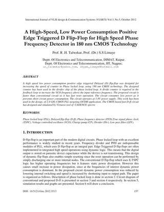
  • 1. International Journal of VLSI design & Communication Systems (VLSICS) Vol.3, No.5, October 2012 DOI : 10.5121/vlsic.2012.3513 157 A High-Speed, Low Power Consumption Positive Edge Triggered D Flip-Flop for High Speed Phase Frequency Detector in 180 nm CMOS Technology Prof. R .H. Talwekar, Prof. (Dr.) S.S Limaye Deptt. Of Electronics and Telecommunication, DIMAT, Raipur. Deptt. Of Electronics and Telecommunication, JIT, Nagpur. ur_talwekar@yahoo.com, shyam_limaye@hotmail.com ABSTRACT A high speed low power consumption positive edge triggered Delayed (D) flip-flop was designed for increasing the speed of counter in Phase locked loop, using 180 nm CMOS technology. The designed counter has been used in the divider chip of the phase locked loop. A divide counter is required in the feedback loop to increase the VCO frequency above the input reference frequency. The proposed circuit is faster than conventional circuit as it has fast reset operation. The circuit consumes less power as it prevents short circuit power consumption. The circuit operates at 1.8V power supply. This work has been used in the design. of 2.4 GHz CMOS PLL targeting OFDM application. The CMOS based fast D-ff circuit has designed and simulated by Virtuoso tool of CADENCE spectre KEYWORDS Phase locked loop (PLL), Delayed flip-flop (D-ff), Phase frequency detector (PFD),True signal phase clock (TSPC), Voltage controlled oscillator (VCO), Charge pump (CP), Divider (Div), Low pass filter (LPF). 1. INTRODUCTION D flip-flop is an important part of the modern digital circuits. Phase locked loop with an excellent performance is widely studied in recent years. Frequency divider and PFD are indispensable modules of PLL, which uses D flip-flop as an integral part. Edge Triggered D flip flops are often implemented in integrated high speed operations using dynamic logic. This means that the digital output is stored on parasitic device capacitance while the device is not transitioning. This design of dynamic flip flops also enables simple resetting since the reset operation can be performed by simply discharging one or more internal nodes. The conventional D flip-flop which uses E-TSPC logic has higher operating frequencies but it features static power dissipation. However this causes small increase in power dissipation, since at the frequencies of interest dynamic power consumption is dominant. In the proposed circuit dynamic power consumption was reduced by lowering internal switching and speed is increased by shortening input to output path. The paper is organized as follows. Description of phase locked loop is done in section 2. Circuit diagram of conventional and proposed D-ff is presented in section 3 and section 4 respectively. In section 5, simulation results and graphs are presented. Section 6 will draw a conclusion.
  • 2. International Journal of VLSI design & Communication Systems (VLSICS) Vol.3, No.5, October 2012 158 2. PHASE LOCKED LOOP (PLL) Phase locked loop is mostly used in wireless communication and data recovery circuits. At present for above mentioned application a low voltage low area and high performance integrated circuits are used which complicates the implementation of such type of integrated circuit. Fig. 2.1 Block diagram of PLL A PLL is a control system that generates a signal that has a fixed relation to the phase of a "reference" signal. A phase-locked loop circuit responds to both the frequency and the phase of the input signals, automatically raising or lowering the frequency of a controlled oscillator until it is matched to the reference in both frequency and phase. Phase locked loops are built of a detector, charge pump, low pass filter, voltage-controlled oscillator (VCO) and frequency divider placed in a negative feedback closed-loop configuration. A phase detector compares two input signals and produces an error signal which is proportional to their phase difference. The error signal is then low-pass filtered and used to drive a voltage-controlled oscillator (VCO) which creates an output frequency. The output frequency is fed through a frequency divider back to the input of the system, producing a negative feedback loop. If the output frequency drifts, the error signal will increase, driving the VCO frequency in the opposite direction so as to reduce the error. Thus the output is locked to the frequency at the other input. 2.1 Phase frequency Detector A phase frequency detector (PFD), is a device which compares the phase of two input signals and provides a signal in the form of phase error. It has two inputs which correspond to two different input signals, usually one from a voltage-controlled oscillator (VCO) and other is a reference source. It has two outputs which instruct subsequent circuitry on how to adjust to lock onto the phase. A charge pump circuit is used to convert the digital signal from the phase frequency detector to analog signal, the output of which is used to control the frequency of the voltage control oscillator. To form a phase-locked loop (PLL), the phase error output of PFD is fed to a charge pump and then to loop filter which integrates the signal to get a sharper and smooth signal so that the disturbances at the input of VCO get minimized. As can be seen from the following diagram, the D flip-flop is an integral part of pfd. Hence to make the operation of PFD faster, a fast D flip-flop is required.
  • 3. International Journal of VLSI design & Communication Systems (VLSICS) Vol.3, No.5, October 2012 159 Fig. 2.1.1 Block diagram of PFD 2.2 Frequency Divider Frequency divider divides the VCO frequency to generate a frequency which is comparable with reference frequency. In the above block diagram, the prescaler and swallow counter together acts as frequency divider. D flip-flop is an integral part of both of them as shown in following diagram: Fig. 2.2.1 Block diagram of conventional swallow counter
  • 4. International Journal of VLSI design & Communication Systems (VLSICS) Vol.3, No.5, October 2012 160 3. CONVENTIONAL D FLIP-FLOP Fig 3.1 Conventional D-ff The conventional D flip-flop which uses E-TSPC logic has higher operating frequencies but it features static power dissipation However this causes small increase in power dissipation, since at the frequencies of interest dynamic power consumption is dominant. 4. DESIGN OF PROPOSED D FLIP-FLOP Fig .4.1 Proposed D-ff Circuit schematic of proposed D flip-flop is as shown in figure 4.1. This flip-flop modifies the TSPC flip-flop to satisfy the required function of D-ff. When input clock (v1) and reset signal (v2) are low, a VDD is developed at the node of common drain of PM4 and NM4. At the rising edge of the clock signal (v1), a zero potential is developed at the node of common drain of PM6 and NM1. Once the node of common drain(A) of PM4 and NM4 is charged to VDD, node of common drain(B) of PM6 and NM1 is not affected by input clock signal because charges at node A turns off NM1 and this prevents the node B from being pulled up. Therefore the node B is disconnected from input node. When reset signal (v2) is applied, node A is disconnected from VDD by PM5 and is connected to ground by NM4. As soon as node A is discharged, node B is pulled up through PM6. The PM5 is added to prevent the short circuit that occurs whenever the reset signal is applied.
  • 5. International Journal of VLSI design & Communication Systems (VLSICS) Vol.3, No.5, October 2012 161 5. SIMULATION RESULTS AND WAVEFORMS The circuit of D–ff for phase frequency detector has been designed and simulated with 180 nm CMOS Technology and the result has shown in fig 5.1.The reduced power dissipation of all transistors are shown in table 5.2 Fig .5.1 Simulation results of Proposed D-ff Table 5.2 Simulation parameters
  • 6. International Journal of VLSI design & Communication Systems (VLSICS) Vol.3, No.5, October 2012 162 6. CONCLUSION A high speed low power consumption positive edge triggered D flip-flop was presented. The D flip-flop was implemented in 180nm CMOS technology. The supply voltage was 1.8V. In the proposed circuit dynamic power consumption was reduced by lowering internal switching and speed was increased by shortening input to output path. REFERENCES [1] Patrik Larsson, “High-speed Architecture for Programmable Frequency Divider and a Dual-Modulus Prescaler IEEE JOURNAL OF SOLID-STATE CIRCUITS, VOL. 31, NO. 5, MAY 1996 [2] Won-Hyo Lee, Sung-Dao Lee and Jun-Dong cho ,“A high speed , low power phase frequency detector and charge pump circuits for high frequency PLL”, IEICE TRANS FUNDAMENTAL, vol E82-A,NO.11 November 1999 [3] Behzad Razavi, “Design of analog cmos integrated circuits”, McGraw-Hill, 2001. [4] Sedra Smith, “Microelectronics and integrated circuits” [5] Ko-Chi Kuo, Feng-Ji Wu , “A 2.4 GHz/5-GHz Low Power Pulse Swallow Counter in 0.18µm CMOS technology”.1-4244-0387-1/06/$20.00©2006 IEEE [6] Nesreen Ismail, “A Simple CMOS PFD for High Speed Applications”, European Journal of Scientific Research ISSN 1450-216X Vol.33 No.2 (2009), pp.261-269 © EuroJournals Publishing, Inc. 2009 http://www.eurojournals.com/ejsr.htm [7] Zheng Yong Zheng ,”A 3.96 GHz phase-locked loop for mode 1 MB-OFDM UWB hopping carrier generation”Vol. 30, No. 7 Journal of Semiconductors July 2009 [8] C.C. Tien, T.M. Tien, “An 802.11a Pulse-Swallow Integer-N Frequency Synthesizer”, Progress in electromagnetic Research C. Vol.7.25-35. 2009 [9] Jung-Yu Chang, Che-Wei Fan, and Shen-Iuan Liu, “A Frequency Synthesizer for Mode-1 MB- OFDM UWB applications”, 978-1-4244-2782-6/09/$25.00 ©2009 IEEE [10] Chun-Lung Hsu and Wu-Hung Lu, “Glitch-Free Single-phase D-FFs for Dual-Modulus Prescrler”, 0- 7803-7889-X/03/S17.00@2003 IEEE. AUTHORS Prof. R. H Talwekar received the BE, ME degree in Electronics Engg.from Nagpur and Pune University in 1993 and 1997 respectively.He is currently a doctoral fellow at Nagpur University. Currently he is Associate professor of Electronics and Telecommunication Deptt. at Disha Institute of Management and Technology in Chhattisgarh Swami Vivekananda Technical University, Bhilai, Chhattisgarh India. His research interest fields are CMOS based analog mixed signal Design. Prof (Dr). S.S. Limaye received the BE and ME in electronics engineering from VNIT, Nagpur and IIT Kharagpur, India in 1971 and 1973 respectively. He received his PhD degree in Electronics Engineering from Nagpur University in 1997. He worked for 15 years in industries and have been working in the field of teaching from last 21 years. Currently he is Principal at Jhulelal Institute of Technology in Nagpur University, Nagpur. His research interest fields s are FPGA based system, and CMOS based wireless IC Design.