Birkett Cable Jointing Kits - Jointers Instruction
•
0 likes•1,191 views

Birkett Cable Jointing Kits - Jointers Instruction

Recommended
Recommended
More Related Content
What's hot
What's hot (18)
Viewers also liked
Viewers also liked (7)
Similar to Birkett Cable Jointing Kits - Jointers Instruction
Similar to Birkett Cable Jointing Kits - Jointers Instruction (20)
More from Thorne & Derrick International
More from Thorne & Derrick International (20)
Recently uploaded
Recently uploaded (20)
Birkett Cable Jointing Kits - Jointers Instruction
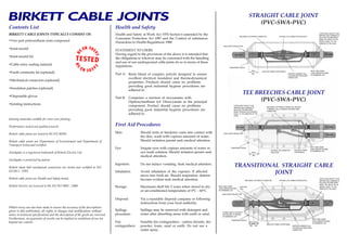
- 1. Contents List BIRKETT CABLE JOINTS TYPICALLY CONSIST OF: ’ Two part polyurethane resin compound ’ Joint mould ’ Joint mould lid ’ Cable entry sealing material ’ Earth continuity kit (optional) ’ Mechanical connectors (optional) ’ Insulation patches (optional) ’ Disposable gloves ’ Jointing instructions Jointing materials suitable for cross core jointing. Performance tested and quality assured. Birkett cable joints are tested to BS EN 50393. Birkett cable joints are Department of Environment and Department of Transport tested and certified. Swishpak’ is a registered trademark of Birkett Electric Ltd. Swishpak’ is protected by patent. Birkett shear bolt mechanical connectors are tested and certified to IEC 61238-1 : 1993. Birkett cable joints are Health and Safety tested. Birkett Electric are licenced to BS EN ISO 9001 : 2000 Whilst every care has been made to ensure the accuracy of the descriptions given in this publication, all rights to changes and modifications without notice to technical specifications and the description of the goods are reserved. Furthermore, no guarantee of results can be implied as conditions of use are beyond our control. Health and Safety Health and Safety at Work Act 1974 Section 6 amended by the Consumer Protection Act 1987 and the Control of substances Hazardous to Health Regulations 1988. STATEMENT TO USERS Having regard to the provisions of the above it is intended that the obligations to whoever may be concerned with the handling and use of our underground cable joints do so in terms of these regulations. Part A: Part B: Resin blend of complex polyols designed to ensure excellent electrical insulation and thermodynamical properties. Products should cause no problems providing good industrial hygiene procedures are adhered to. Comprises a mixture of isocyanates with Diphenylmethane 4,4° Diisocyanate as the principal component. Product should cause no problems providing good industrial hygiene procedures are adhered to. First Aid Procedures Skin: Should resin or hardener come into contact with the skin, wash with copious amounts of water. Should irritation persist seek medical attention. Eye: Ingestion: Irrigate eyes with copious amounts of water or eye wash solution. Should irritation persist seek medical attention. Do not induce vomiting. Seek medical attention. Avoid inhalation of the vapours. If affected move into fresh air. Should respiratory distress become evident seek medical attention. Inhalation: Maximum shelf life 2 years when stored in dry or air-conditioned temperature of 0®C - 60®C. Storage: Disposal: Spillage may be removed with detergent and water after absorbing areas with earth or sand. Spillage procedure: Suitable fire extinguishers - carbon dioxide, dry powder, foam, sand or earth. Do not use a water spray. Fire extinguishers: Via a reputable disposal company or following instructions from your local authority. STRAIGHT CABLE JOINT (PVC-SWA-PVC) TEE BREECHES CABLE JOINT (PVC-SWA-PVC) TRANSITIONAL STRAIGHT CABLE JOINT OPTIONAL LIVE CONNECTOR INSULATIONMECHANICAL OR FERRULE CONNECTOR CABLE ENTRY SEALING TAPE TRANSPARENT MOULD MIN 40mm INSULATED TINNED COPPER BRAID MAINTAIN A MINIMUM 10mm CLEARANCE BETWEEN BARE CONNECTORS METAL RING UNDER CABLE ARMOUR SECURED BY WORMDRIVE CLIP OUTER CABLE SHEATH TO BE ABRAIDED AND A MINIMUM OF 40mm MUST BE MAINTAINED INSIDE THE MOULD OR AN AMOUNT EQUAL TO THE DIAMETER OF THE CABLE OUTER CABLE SHEATH TO BE ABRAIDED AND A MINIMUM OF 40mm MUST BE MAINTAINED INSIDE THE MOULD OR AN AMOUNT EQUAL TO THE DIAMETER OF THE CABLE MECHANICAL OR FERRULE CONNECTOR. MAINTAIN A MINIMUM 10mm CLEARANCE BETWEEN BARE CONNECTORS METAL RING UNDER CABLE ARMOUR SECURED BY WORMDRIVE CLIP INSULATED TINNED COPPER BRAID OPTIONAL LIVE CONNECTOR INSULATION MIN 40mm TRANSPARENT MOULD CABLE ENTRY SEALING TAPE OPTIONAL LIVE CONNECTOR INSULATIONMECHANICAL OR FERRULE CONNECTOR OUTER CABLE SHEATH TO BE ABRAIDED AND A MINIMUM OF 40mm MUST BE MAINTAINED INSIDE THE MOULD OR AN AMOUNT EQUAL TO THE DIAMETER OF THE CABLE INSULATED TINNED COPPER BRAID MAINTAIN A MINIMUM 10mm CLEARANCE BETWEEN BARE CONNECTORS METAL RING UNDER CABLE ARMOUR SECURED BY WORMDRIVE CLIP MIN 40mm MIN 40mm TRANSPARENT MOULD PLUMBED EARTH CONTINUITY AND SECURED TO ARMOUR BY WORMDRIVE CLIP CABLE ENTRY SEALING TAPE METAL RING UNDER CABLE ARMOUR SECURED BY WORMDRIVE CLIP MOISTURE SEAL WWW.CABLEJOINTS.CO.UK THORNE & DERRICK UK TEL 0044 191 490 1547 FAX 0044 477 5371 TEL 0044 117 977 4647 FAX 0044 977 5582 WWW.THORNEANDDERRICK.CO.UK
- 2. Cable Jointing Instructions The following instructions are to be taken as cable jointing recommendations complying with the test requirements of BS EN 50393. The installation of cable joints must be entrusted to appropriately qualified and experienced craftsmen. BS 6910-2 is the code of practice for the installation of cable joints on site using these materials. It is assumed that the cables are de-energised. N.B. Before beginning the installation of the cable joint, please read the Health and Safety guidelines. ’ Clean exposed cable and ensure that the cable joint area is dry. For stepped end joint moulds, using a hack-saw cut the stepped ends of the mould so as to accommodate the size of the cable. Set the cables level. Remove the outer sheath ensuring that the manufacturer°s recommendation of 40mm is maintained within the mould wherever possible or an amount equal to the diameter of the cable. For paper lead cables a metal binder should be applied to the outer hessian sheath at a distance of 40mm within the mould. It is a manufacturer‘s recommendation that a further distance of 40mm must be allowed as a longitudinal seal within the cable joint. Abrade the remaining outer 40mm cable sheath that lies within the mould to the cable entry point. Cut and pull back steel wire armouring and put into place the metal ring. Each metal ring must be firmly placed under the armour. Fold back steel wire armouring over the rings with no overlapping. Apply wormdrive clips. Trim off unwanted armour wires in line with the end of each armour ring ensuring a 10mm radial cover thickness of bedding at cutback wherever possible. Cut and remove the exposed inner bedding to reveal the cores. For paper lead cables cut through the exposed lead sheath to reveal the paper insulated cores. It is important that sufficient lead sheathing is still exposed to allow secure installation of the earth continuity. When removing the lead sheath special care should be taken not to damage the cores. Cord or twine should be tied securely around the paper insulated cores to prevent unwinding. Straighten the cables and spread the cable cores. For multi-core and multi-pair cables remove all loose bedding and grease. Cut and remove the appropriate amount of insulation respective to the type of cable connector being used. ’ ’ ’ ’ ’ When using mechanical connectors the copper conductors should be wrapped in brass gauze to ensure electrical stability between the copper and aluminium. Connect the correct cores using the recommended Birkett mechanical or compression-type cable connectors. Maintain a minimum 10mm clearance between each jointed uninsulated connector. Apply the green insulated tinned copper braid and strip back an appropriate amount to ensure a good contact. Fasten the tinned copper braid to the armour using the wormdrive clips. For paper lead cables the lead sheath provides the earth therefore an adequate bonding system MUST BE INSTALLED to reinstate the earth continuity. This is best achieved by a method known as ®plumbing‘. Continue the tinned copper braid under the armour and secure using the wormdrive clip. It is important that an earth continuity is securely installed that matches the earth fault rating of the cable. Set the cables level. Clean exposed cable and ensure the joint area is dry. For paper lead cables apply a moisture seal around the lead sheath. Place the two halves of the mould around the joint with the pour hole section at the top. Simply snap together maintaining the 10mm clearance between each uninsulated joint component and inside surface of the mould wherever possible. Apply cable entry sealing tape. Support the mould with backfill before pouring compound. Refer to appropriate mixing and pouring Instructions. Ensure all component parts have been encapsulated in resin compound. Insert mould lid and energise cable. Completed joint should be left for a minimum of 1 hour after pouring to allow sufficient curing before back filling. ’ ’ ’ ’ ’ ’ ’ ’ ’ ’ ’ ’ (Read mixing and pouring instructions fully before commencing) MIXING INSTRUCTIONS - SWISHPAK Use gloves supplied. Tip Swishpak out of the canister. When the ambient temperature is below 10®C warm the bag by kneading resin by hand. Hold the Swishpak and using your thumb, through the bag locate the seal on the base of the pouring nozzle inside the Swishpak . By applying pressure, break the seal allowing the hardener to flow into the Swishpak . Swish contents thoroughly for approximately 3 minutes, allowing the resin to flow freely between the Swishpak and pouring nozzle. Ensure all the hardener in the pouring nozzle is mixed and an even colour obtained. After mixing, remove screw cap from the Swishpak . Break the seal on the pouring nozzle and allow resin to be poured. Squeeze the Swishpak thoroughly until empty. POURING INSTRUCTIONS Ensure the joint area is dry before pouring. The allowable pour time at an ambient temperature of 20®C with standard resin compound is approximately 8 minutes for each pack. All joint components must be entirely encapsulated in compound. Standard resin compound will gel in approximately 20 minutes at an ambient temperature of 20®C. Allow 20 minutes after completion of pouring before energising cable. If optional connector insulation has been applied the cable may be energised immediately. Allow one hour after initial pouring to backfill the cable joint. Should resin compound come into contact with the skin, wash with copious amounts of water. ’ ’ ’ ’ ’ ’ ’ ’ ’ ’ ’ ’ Two Part Polyurethane Resin Compound Bridge House, Longwick Road, Princes Risborough, Buckinghamshire HP27 9RS Telephone: 01844 274480 Facsimile: 01844 274470 Email: info@birkett-electric.com Internet: www.birkett-electric.com B20/01 23 Jan 2007 Issue 8 I RK ET CA L I J TCON RS ’ ’ ’ WWW.CABLEJOINTS.CO.UK THORNE & DERRICK UK TEL 0044 191 490 1547 FAX 0044 477 5371 TEL 0044 117 977 4647 FAX 0044 977 5582 WWW.THORNEANDDERRICK.CO.UK