More Related Content
Similar to Foc pulling (20)
Foc pulling
- 1. Cable Preparation and Pulling
Procedure Best Practices for
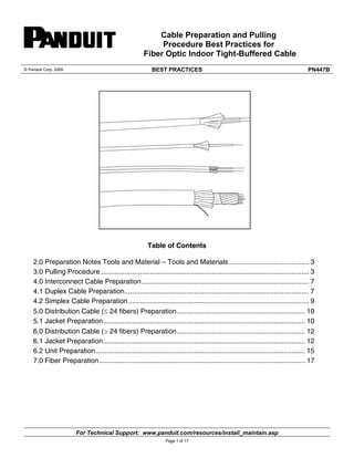
Fiber Optic Indoor Tight-Buffered Cable
© Panduit Corp. 2009 BEST PRACTICES PN447B
Table of Contents
3
2.0 Preparation Notes Tools and Material – Tools and Materials ......................................... 3
3.0 Pulling Procedure ........................................................................................................... 3
4.0 Interconnect Cable Preparation ...................................................................................... 7
4.1 Duplex Cable Preparation ............................................................................................... 7
4.2 Simplex Cable Preparation ............................................................................................. 9
5.0 Distribution Cable (≤ 24 fibers) Preparation .................................................................. 10
5.1 Jacket Preparation ........................................................................................................ 10
6.0 Distribution Cable (> 24 fibers) Preparation .................................................................. 12
6.1 Jacket Preparation ........................................................................................................ 12
6.2 Unit Preparation ............................................................................................................ 15
7.0 Fiber Preparation .......................................................................................................... 17
For Technical Support: www.panduit.com/resources/install_maintain.asp
Page 1 of 17
- 2. © Panduit Corp. 2009 BEST PRACTICES PN447B
DISCLAIMER OF WARRANTIES AND LIMITATION OF LIABILITIES
The practices contained herein are designed as a guide for use by persons having technical skill at their own
discretion and risk. The recommended practices are based on average conditions. Panduit does not
guarantee any favorable results or assume any liability in connection with this document.
In addition, the materials and hardware referenced herein appear as examples, but in no way reflect the only
tools and materials available to perform these installations.
Local, State, Federal and Industry Codes and Regulations, as well as manufacturers requirements, must be
consulted before proceeding with any project. Panduit makes no representations of, nor assumes any
responsibility for, the accuracy or completeness of this document. Panduit disclaims any liability arising from
any information contained herein or for the absence of same.
For Technical Support: www.panduit.com/resources/install_maintain.asp
Page 2 of 17
- 3. © Panduit Corp. 2009 BEST PRACTICES PN447B
For Technical Support: www.panduit.com/resources/install_maintain.asp
Page 3 of 17
1.0 General Information
This instruction manual is a step-by-step guide for end
and termination of tight-buffered cable, including sheath
removal, core preparation, and fiber preparation. Local
company practices and specifications may be in place
concerning cable access and how it relates to a specific
product or application. Modifications that do not exceed
the cable’s optical and mechanical performance
specifications may be made to accommodate local
company practices and specifications. These
modifications should be made at the discretion of local
company users.
Step-by-step illustrations have been provided
for your reference and orientation as you follow
the procedures.
2.0 Preparation Notes
Gather the tools and materials to be used for the
job and make sure they are approved by your
company for use in the field and are in good
working order.
Record for future reference the cable
identification markings, which consist of sheath
number, footage, and cable description codes
printed on the cable outer sheath.
3.0 Pulling Procedure
Tools and Materials
1. Eye and Hand Protection
2. Linesmen Pliers
3. Tight Buffer Stripping Tool
4. Wire Stripping Tool
5. Scissors/Snips
6. Sheath Knife
7. Scissors/Snips
8. Needle Nose Pliers
- 4. © Pa
anduit Corp. 2009
70
Le
00 Industrial D
exington, SC
1. Ge
1.1 T
mesh
optic
cable
Drive
29072
eneral
This procedur
h pulling grip
cables that a
s include:
• Tight Buffer
• Unitized cab
• Breakout cab
Refer to the
og for the max
led.
This issue in
ocking armor.
1.2
Catal
install
1.3 T
interlo
2. P
2.1
Pull
Grip
ling Proce
on Multifi
re provides ins
on Panduit m
are not conne
T PRACTICE
edure: Ins
ber Tight-
structions for i
multifiber tight
ectorized. Exa
red cables
bles
bles
e appropriate
ximum tensile
ncludes grip
.
Precautions
General Pre
WA
pro
rec
cu
an
ecautions
Safety G
Glasses
ARNING: The
otect the eyes
commended w
tting fiber. Pi
d can damage
S
stalling a W
-Buffered
nstalling a wir
t buffered fibe
amples of suc
cable specific
load rating of
re
er
ch
cation sheet o
the cable to b
installation o
e wearing of sa
s from acciden
.
when handling
eces of glass
e the cornea o
or
be
on cables wit
afety glasses
ntal injury is s
g chemicals an
fiber are very
of the eye easi
For Techn
to
strongly
nd
y sharp
ily.
nical Suppor
BEST
th
rt: www.pan
Wire Mes
Fiber Op
2.2 Ca
sh Pulling
tic Cables
able Handlin
s
g Precautio
Caution: Fibe
excessive pu
Consult the c
cable you are
sharply than
radius. DO n
cable than sp
allow it to kin
can alter the t
cable – the ca
er optic cable
lling, bending
cable specifica
e installing. D
the minimum
ot apply more
pecified. Do n
nk. Doing so m
transmission
able may have
3. Tools a
3.1 The fol
duit.com/res
Page 4 of 17
and Materials
llowing tools a
o complete th
ems® pulling g
cutters (diago
suring tape
y knife with ho
tape, ¾ in. (
on tape, ¾ in
es
sors
el, ball bearin
wrench or scr
y knife with ho
required to
• Kelle
• Side
• Meas
• Utility
knife
• Vinyl
• Fricti
• Glove
• Sciss
• Swiv
• Hex w
• Utility
sources/insta
all_maintain.
.asp
Issue 1
n
is sensitive to
g and crushing
ation sheet for
o not bend ca
recommende
e pulling force
ot crush the c
may cause dam
characteristic
e to be replace
s
and materials
his procedure
grip
onal cutting p
ook blade or c
19.1mm)
n. (19.1mm)
ng type
rewdriver
ook blade
PN447B
October 2, 2009
o
g forces.
r the
able more
d bend
e to the
cable or
mage that
cs of the
ed.
s are
:
pliers)
cable
9
- 5. © Panduit Corp. 2009 BEST PRACTICES PN447B
For Technical Support: www.panduit.com/resources/install_maintain.asp
Page 5 of 17
4. Pulling Grip Selection and Installation
4.1 Prior to installation, the proper size grip
must be chosen for the cable to be pulled.
Grip selection is based on the outside diameter
of the cable (Figures 2 and 3)
Cable
Diameter
PVC Jacket
Aramid Yarn
Coated Fiber
Rip Cord
Cable Diameter and Grip Size
If cable diameter is in the
range of……
Kellems part
number
2.5 ‐ 5.6mm (0.10 to 0.22in.) 033‐29‐1182
5.3 ‐ 9.0mm (0.21 to 0.35in.)
9.1 ‐ 12.2mm (0.36 to 0.48in.)
12.3 ‐ 15.5mm (0.49 to 0.61in.)
15.6 ‐ 18.5mm (0.62 to 0.73in.)
18.6 ‐ 22.1mm (0.74 to 0.87in.)
22.2 ‐ 25.4mm (0.88 to 1.0in.)
033‐29‐1182
033‐29‐1184
033‐29‐1185
033‐29‐1186
033‐29‐1187
033‐29‐1188
Figure 2 Non-utilized Premises Cable
Cable Diameter
Aramid Yarn
Cable Jacket
Dielectric
central member
6‐fiber subunit
Rip Cord
Cross section of a 48-fiber
Unitized Cable
4.3 Once the proper grip is obtained, inspect it for
damage broken wires, bulges due to stress, rust, etc.
Grasp the pulling eye in one hand (gloves are
recommended) and smooth out the mesh with the
other, tightening the wires. Figure 4 illustrates the
technique, which is critical when reusing grips.
4.2 Generally speaking, use the smallest grip which will
fit over the cable’s outer jacket without excessive difficulty.
Measure the cable diameter and determine the proper grip
by locating the diameter in Table 1.
Figure 4
4.4 To ease installation, trim the end of the cable with side
cutters to remove any protruding buffered fibers, yarn, or
central member (Figure 5)
Figure 5
4.5 It is necessary to remove a section of outer jacket
equal to half of the length of the mesh area of the grip.
Mark this distance from the end of the cable with a
permanent marker (Figure 6)
Figure 6
- 6. © Pa
4.6
cable
relax
(3 in
anduit Corp. 2009
Use a pump
e by bringin
xing them unt
.) beyond the
Figu
4.7
you
jack
For
jack
com
rem
CAU
blad
the o
units
imm
Figu
ure 8
4.8
laye
expo
direc
ping action to
ng your han
til the end of t
e mark made i
≥ 7.5 cm
(≥ 3.0in.
o “walk” the g
nds together
the grip is at l
in step 4.5 (F
sheath remov
g to remove th
grip over the
r and then
least 7.5 cm
igure 7)
al procedure
he marked len
cables, first
end of the
ether with vin
aining jacket.
T PRACTICE
for the cable
ngth of outer
remove 15 c
cable. Tap
nyl electrical
making ring c
ife, do not cut
oing so may d
ble component
w it.
Beginning a
er of friction
osed cable co
ction of the su
IMP
frict
cou
Figu
Mark
ure 7
Follow the s
are installing
ket (Figure 8).
non-unitized
ket from the
mponents toge
ove the rema
UTION: When
de or cable kni
outer jacket-d
s or other cab
mediately below
cm (6 in.) of
pe the cable
tape. Then
cuts with a ho
t all the way th
damage the su
ts which lie
at the end of t
n tape over
ore. The frict
un-units or bu
PORTANT: Do
tion tape. Ele
uld affect the p
ure 9
ook
hrough
ub
the outer jack
the entire le
tion tape shou
uffered fibers
o not use black
ctrical tape ha
pulling grip’s p
ket, wrap one
ength of the
uld follow the
twists.
k electrical tap
as a slick oute
performance.
Frictio
over
n tape
core
For Tech
pe in place of
er surface and
Ou
ter jacket
hnical Suppo
BEST
d
ort: www.pan
S
4.9
cable
core
Tug
“Walk” the
e core. Sm
, moving from
on the grip to
Figu
4.10
on th
of th
throu
The t
again
e grip over t
ooth the me
m the pulling
o tighten it aga
ure 10
Starting at
he cable jacke
he grip. The
ugh the tape.
tape must be t
nst the cable co
Tug
the friction ta
esh back ove
eye to the c
ainst the core
least 2.5 cm
et wrap vinyl
e mesh’s imp
(Figure 11).
tight because i
ore.
on the grip sl
Figu
ure 11
Note
alway
the p
that i
4.11
bear
insta
(1.0 in.) belo
tape TIGHTL
print should s
it helps compr
ightly to tighte
en it.
or more viny
nal, outside lay
is layers the ta
g as it moves th
the pulling ey
nd pulling tap
w ready for the
: When two
ys wrap the fin
pulling eye. Th
it will not snag
ing swivel an
allation is now
Fig
Grip
4.12
(36 i
the e
wate
is pro
gure 12
Removal
After comp
n.) behind th
exposed cab
er intrusion. S
otected from d
nduit.com/re
Page 6 of 17
Connect t
yl tape layers
yer from the ca
ape like roofing
hrough the duc
ye to the app
pe. (Figure 12
e cable pull.
pull, cut the c
ce a protectiv
tape in place
ed splicing sla
pletion of the
he grip. Plac
le end and t
Store the coile
damage.
esources/ins
tall_maintain
n.asp
PN447B
ape-covered
er the cable
cable jacket.
e (Figure 10)
ow the mesh
LY to the top
show clearly
ress the mesh
are desired,
able jacket to
g shingles, so
ct.
ropriate ball
2). The grip
cable 91 cm
ve cap over
e to prevent
ack so that it
- 7. © Panduit Corp. 2009 BEST PRACTICES PN447B
For Technical Support: www.panduit.com/resources/install_maintain.asp
Page 7 of 17
4.0 Interconnect Cable
This procedure is intended to be used with
interconnect cables, including both duplex
and simplex cable designs. Two simplex
cables comprise a single duplex cable.
The length of cable sheath to be removed
will depend on local company practices and
specifications. Designate this distance
from the end of the cable on the outer
sheath.
4.1 Duplex Cable Preparation
There are two types of duplex cables.
Sheathed Duplex
Enclosing two simplex cables in an outer
sheath created a duplex cable. To prepare
this type of cable, with a sheath knife, cut
the outer jacket at the designated distance.
Gently flex the cable at the ring cut to
separate or removal.
Remove and discard the sheath section.
No more than eight inches of sheath should
be removed at once. Therefore, eight-inch
sections must be removed until the final
desired length is achieved.
With the outer sheath the two internal
simplex cables are not exposed. At this
point advance to Section 4.2 for simplex
cable preparation procedures.
Duplex and simplex cables
Ringing a sheathed cable outer jacket with a sheath knife.
Flexing the sheathed cable at the ring cut
Removing the outer section of the jacket
- 8. © Panduit Corp. 2009 BEST PRACTICES PN447B
For Technical Support: www.panduit.com/resources/install_maintain.asp
Page 8 of 17
Zip-cord Duplex Cables
Two simplex cables joined via a
connecting membrane create a duplex
cable. This type of duplex cable is
referred to as zip-cord.
To prepare a zip-cord style duplex
cable, use an approved sheath knife to
carefully separate the duplex cable into
two simplex cables. Cut the membrane
connecting the two simplex cables.
Approximately one inch is sufficient.
Firmly grasp the two separated simplex
cables and pull them apart. They
should separate easily.
Separate the duplex cable into two
simplex cables for the distance
designated by local splicing/termination
guidelines and vendor specifications.
At this point, advance to Section 4.2 for
Simplex Cable Preparation procedures.
Cutting the membrane connecting the two cables
Carefully separating the two cables by pulling them apart
- 9. © Panduit Corp. 2009 BEST PRACTICES PN447B
For Technical Support: www.panduit.com/resources/install_maintain.asp
Page 9 of 17
Cutting the simplex jacket to expose the tight-buffered fiber
Cutting the strength member yarns
4.2 Simplex Cable Preparation
The length of sheath to be removed from
each simplex cable will be determined by
local splicing/termination guidelines and
vendor specifications.
The manufacturer of the connector type
being installed specifies the correct removal
length for each cable component.
Information similar to the following
illustration should be provided with the
connector.
Using an approved set of strippers that do
not come close to a diameter small enough
to damage the fiber, select one simplex
cable and cut the jacket at the length as
specified by the connector manufacturer.
Remove the length of outer jacket. This will
expose the tight-buffered fiber and the
strength member yarn. Separate the
strength member yarn from the tight-buffered
fiber.
Cut off the strength members leaving the
length specified by the connector
manufacturer.
At this point advance to Section 7.0 for Fiber
Preparation procedures.
Simplex cable
Removing the outer length of the simplex jacket
- 10. © Panduit Corp. 2009 BEST PRACTICES PN447B
For Technical Support: www.panduit.com/resources/install_maintain.asp
Page 10 of 17
5.0 Distribution Cable (24 Fibers or
less Preparation)
This procedure is intended for use with
distribution cable with 24 or fewer tight-buffered
fibers. The 24-fiber design consists
of a core of 12 tight-buffered fibers around
an upjacketed central strength member.
Stranded around this core are 12 more
fibers with filler units to complete the layer.
Strength member yarns and a jacket cover
the core.
The 12-fiber design is similar to the 24-fiber
design without the outer layer of fibers. For
these procedures the 24-fiber design will be
shown. The sheath removal for the 12-fiber
design is identical with the exception of the
outer core layer of fibers.
5.1 Jacket Preparation
The length of cable sheath to be removed
will depend on local company practices and
vendor specifications. If not otherwise
specified, six feet should be sufficient.
Designate this distance from the end of the
cable on the outer sheath. Using an
approved sheath knife, “ring” the
circumference of the jacket at the
designated distance.
Using a sheath knife, “ring” the
circumference of the jacket about six to eight
inches from the end of the cable.
Gently flex the cable at the cut to separate
for removal.
The end piece of the jacket can be removed
and discarded. This will expose the strength
member yarns and ripcord.
Ringing the cable with a sheath knife
Flexing the cable at the ring cut to separate sheath sections
Removing the outer cable sheath section
Exposing the ripcord
- 11. © Panduit Corp. 2009 BEST PRACTICES PN447B
Grasp and wrap the ripcord around the
needle-nose pliers.
Pull the ripcord back to the first
predetermined ring cut.
Carefully separate the strength member
yarns from the core and cit to the length
prescribed by local practices and vendor
specifications.
At this point advance to Section 7.0 for Fiber
Preparation procedures.
Grasping the ripcord with needle nose pliers
Pulling the ripcord to the predetermined ring cut
For Technical Support: www.panduit.com/resources/install_maintain.asp
Page 11 of 17
Removing the split cable sheath
Cutting the strength member yarns
- 12. © Panduit Corp. 2009 BEST PRACTICES PN447B
For Technical Support: www.panduit.com/resources/install_maintain.asp
Page 12 of 17
6.0 Distribution Cable (Greater than
24 Fibers) Preparation
This procedure is intended for use with
distribution cable with more than 24 fibers.
The 72-fiber version of this design is used
here for demonstration purposes. The
procedure explained here will work with all
other distribution cable with more than 24
fibers.
The 72-fiber cable consists of six jacketed
unites stranded around an upjacketed CSM.
There is tape and a jacket round each unit.
Around the core of the six units are stranded
strength member yarns – on top of which the
outer jacket is applied.
6.1 Jacket Preparation
The length of cable sheath to be removed
will depend on local company practices and
vendor specifications. Designate this
distance from the end of the cable on the
outer sheath.
Using the approved sheath knife, “ring” the
circumference of the outer jacket at the
designated distance.
Using the sheath knife, “ring” the
circumference of the outer jacket about six
to eight inches from the end of the cable.
The end piece of jacket can be removed and
discarded. This will expose the strength
member yarns and ripcord.
Ringing the cable sheath with a sheath knife
Flexing the cable at ring cut to separate sheath sections
Exposing the ripcord after removal of jacket end piece
- 13. © Panduit Corp. 2009 BEST PRACTICES PN447B
Grasp and wrap the ripcord around the
needle-nose pliers.
Pull the ripcord back to the first
predetermined ring cut.
If a ripcord is not provided carefully slit the
outer jacket to the predetermined ring cut
using a sheath knife.
Remove this length of the jacket and discard
it.
Separate the strength member yarns from the
core and cut to the length prescribed by local
company practices and vendor specifications.
Grasping the ripcord with needle-nose pliers and pulling back
to predetermined ring cut
Removing the split cable sheath
Cutting the strength member yarns
For Technical Support: www.panduit.com/resources/install_maintain.asp
Page 13 of 17
- 14. © Panduit Corp. 2009 BEST PRACTICES PN447B
The core of the six jacketed units is
wrapped with a clear tape. This tape can
now be unwrapped and discarded. This will
expose the individual jacketed
units for preparation.
The six jacketed units are stranded around
the CSM. Unwind the units to expose the
CSM.
Using approved cutters cut the CSM to the
desired length for termination. Unwinding the clear tape
Exposing the central strength member
Cutting the central strength member
For Technical Support: www.panduit.com/resources/install_maintain.asp
Page 14 of 17
- 15. © Panduit Corp. 2009 BEST PRACTICES PN447B
For Technical Support: www.panduit.com/resources/install_maintain.asp
Page 15 of 17
6.2 Unit Preparation
The length of unit jacket to be removed will
depend on local company practices and
vendor specification. It is important to use
care to avoid damaging the tight-buffered
fibers in the core of the unit and also to
avoid cutting the ripcord.
Using the sheath knife gently “ring” the
circumference of the unit jacket about four to
six inches from the end of the unit. Again, it
is very important to use care to avoid
damaging the tight-buffered fibers in the
core of the unit and also to avoid cutting the
ripcord.
Gently flex the unit at the cut to separate for
removal.
The end piece of unit jacket can be removed
and discarded. This will expose the ripcord
and the clear tape wrapped around the core.
Cut the outer strength members
Flexing the unit of the ring cut to separate jacket sections
Removing the end piece of the unit jacket
- 16. © Panduit Corp. 2009 BEST PRACTICES PN447B
Grasp and wrap the ripcord around the
needle-nose pliers.
Pull the ripcord back to the predetermined
length. This will depend on local company
practices and vendor specifications. Peel
the jacket away to this point.
Using the approved snips or scissors cut this
length of jacket away. Use care to avoid
cutting any of the tight-buffered fibers.
The unit’s tight-buffered fibers are
surrounded with strength member yarns.
Carefully separate the tight-buffered fibers
from the strength member yarns.
Using approved snips or scissors cut the
strength member yarns to the desired length
for termination.
At this point advance to Section 7.0 for fiber
Preparation procedures.
Grasping and pulling the ripcord with needle-nose pliers
For Technical Support: www.panduit.com/resources/install_maintain.asp
Page 16 of 17
Exposing the ripcord
Peeling off the unit jacket
- 17. © Panduit Corp. 2009 BEST PRACTICES PN447B
For Instructions in Local Languages
and Technical Support:
www.panduit.com/resources/install_maintain.asp www.panduit.com
E-mail:
cs@panduit.com
Fax:
(708) 444-6993
Page 17 of 17
7.0 Fiber Preparation
Using an approved stripping tool that scores
the 900μm diameter tight-buffered coating,
but does not touch the 125μm diameter of
the fiber, remove the tight-buffered coating.
For best results, strip and remove two
inches or less at a time. When stripping
either the tight-buffered coating or the fiber’s
coating, hold the fiber carefully to avoid tight
bends, while placing the fiber under tension.
Small bend diameters and abrupt high
stress can damage or break the fiber.
With the fibers now exposed and accessible
for termination refer to local
splicing/termination guidelines and vendor
specification.
Refer back to Section 4.2 Simplex Cable
Preparation for an example of manufacturer
supplied connector termination instructions.
Removing the tight buffering