The document discusses the flight control systems of the Boeing 747-400, including descriptions of:
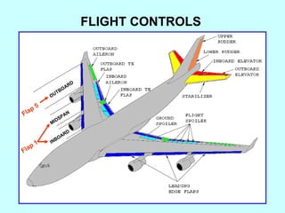
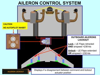
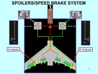
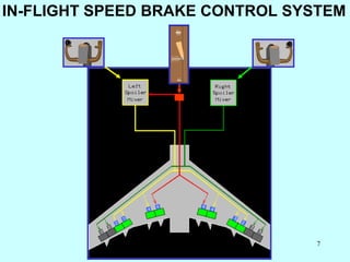
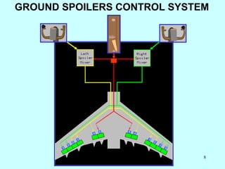
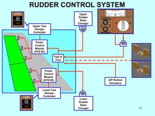
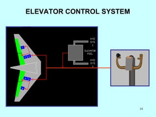
1) The aileron, spoiler, elevator, rudder, and flap control systems. It describes the components and functions of each system.
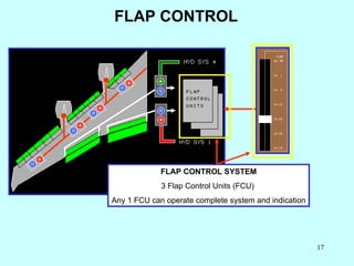
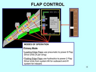
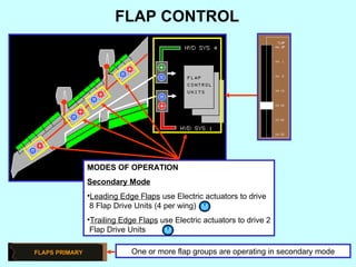
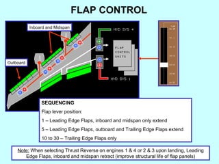
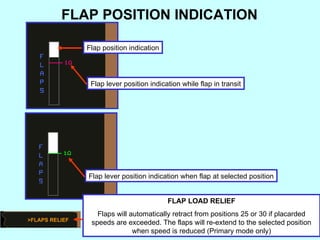
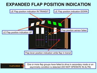
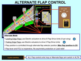
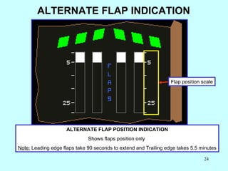
2) The modes of operation for the flap control system including primary, secondary, and alternate modes. It provides details on flap sequencing and position indication.
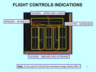
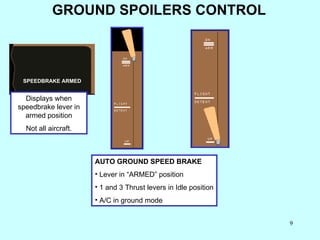
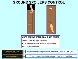
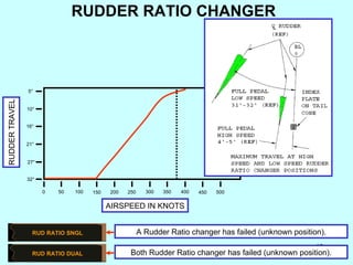
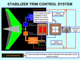
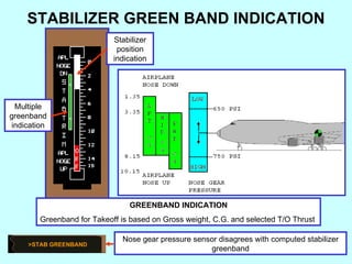
3) Indications that may appear related to problems with the flight control systems like disagreements between sensors or failures in certain components.