SlideShare a Scribd company logo
1 of 11
Download to read offline
The International Journal Of Engineering And Science (IJES)
|| Volume || 3 || Issue || 12 || December - 2014 || Pages || 57-67||
ISSN (e): 2319 – 1813 ISSN (p): 2319 – 1805
www.theijes.com The IJES Page 57
Modelling Of Underground Cables for High Voltage
Transmission
1,
Omorogiuwa Eseosa , 2,
Obi Patrick. I
1,
Department of Electrical/Electronic Engineering College of Engineering, University of Port Harcourt
2,
Department of Electrical/Electronic Engineering Anambra State University, .Anambra
--------------------------------------------------ABSTRACT--------------------------------------------------------
The high failure rates and economic implications of regularly maintaining Overhead lines hasnecessitated the
need for using Underground Cable system. This paper covers the current carrying capacity of underground
cables under three states namely, the steady, transient and short circuit states. Also covered is the reactive
power generated in underground cables during operation.
---------------------------------------------------------------------------------------------------------------------------------------
Date of Submission: 07 November 2014 Date of Accepted: 15 December 2014
---------------------------------------------------------------------------------------------------------------------------------------
I INTRODUCTION
A Micro-hydro means a plant of small power, having about 100 kW. The Micro-hydro power plants represent
lately, one one the way out to clean energy generation, due to the following advantages: Require water sources
of low flow and fall; Don’t need big investments; Are environment friendly from the equipment point of view;
Are very useful for isolated areas; Can autonomously function; Can be easily used by anybody. In this work,
the design of a micro-hydro power plant with robust governor for improve system performance is considered.
All over Nigeria, there are many rivers both large and small (hydropower potential sites) and around some of
them little communities with no electricity because they are too isolated to be connected to the electricity grid
(network). Nigeria has not being able to exploit her small rivers hydropower potential site because of the none
availability of suitable hydro plant capable of utilizing low water head and flow from small rivers to generate
power (Prof. O.O. Adewoye 2009), but has only partially succeeded in exploiting her large rivers hydropower
potential sites, by building large scale hydroelectric power plant (e.g. Kainji hydropower plant, Jebba
hydropower plant, Shiroro hydropower plant) to generate huge amounts of power from water stored behind
massive dams. According to the international energy agency (IEA), large-scale hydroelectric plants currently
supply 29% of Nigeria electricity supply. However, such kind of projects requires tremendous amounts of land
for impoundment, relocation of people from the land and flood-control, and often they produce many
environmental impacts despite their emission-free electricity production. One main problem of hydropower
electricity is to keep the constant frequency value (the constant speed value) because these plants are affected by
change in the regime of river. In a power system operation such as hydro electricity plants, system frequency
varies depending on the difference between demand , therefore generated power load-frequency control is very
important for supplying efficiently electrical power of good quality, as the consumers want continuous, stabile,
quality and reliable power at rated frequency and voltage . For a power system to be term reliable, constant
frequency value must be provided against the varying load value. Hence this project aims to design a reliable
hydroelectric power plant that is devoid of the problem associated with large scale hydro plant, and capable of
utilizing the smaller rivers in Nigeria to generate electricity.
II DESIGN OBJECTIVE
To design an hydroelectric power plant that does not require:-
 A large water reservoir or Dam
 Relocation of people from there land and need for flood control
 Connection to the power grid to supply electricity, (hence it can serve remotely located community.)
 To design an hydroelectric power plant capable of utilizing low water head and flow from small rivers
to generate power
 To design an hydroelectric power plant capable of providing constant frequency value against the
varying load value.
This design will help in providing guide for the construction of suitable hydroelectric plant capable of utilizing
low water head and flow from small rivers to generate power, hence enabling the country to start exploiting her
small hydro potential sites. The construction of hydroelectric power plant in the country that is truly
Modelling Of Underground Cables For High...
www.theijes.com The IJES Page 58
environment friendly is achieved via better power load-frequency control on hydroelectric power plant in the
country and beyond.
III DESIGN METHODOLOGY:
In this work, micro-hydro power plant, consisting of five elements: water tank and valve, supply
pipe, chain type hydro turbine, generator and controller is considered. The work presents a systemic
approach on Micro-hydro plant, starting with the achievement of block diagram with one control closed loops.
Discussion /analysis, as well as modeling and simulation of the electro mechanical part (hydro turbine,
generator) was considered. The results of this work prove the correctness of this design that could be used in
practical applications. The design is limited to hydro electric power plant for use in run-of-river’ scheme and
only the electro-mechanical components of the plant (i.e. the turbine–generator) and the Controller (i.e. the
governor)
IV LITERATURE REVIEW
Hydropower is a renewable, non-polluting and environmentally benign source of energy. Hydropower is based
on simple concepts. Moving water turns a turbine, the turbine spins a generator, and electricity is produced.
Many other components may be in a system, but it all begins with the energy in the moving water. The use of
water falling through a height has been utilized as a source of energy since a long time. (Dilip Singh 2009) It is
perhaps the oldest renewable energy technique known to the mankind for mechanical energy conversion as well
as electricity generation. In the ancient times waterwheels were used extensively, but it was only at the
beginning of the 19th Century with the invention of the hydro turbines that the use of hydropower got
popularized. Hydropower was the most common way of electricity generating in the early 20th century.
The first commercial use of hydroelectric power to produce electricity was a waterwheel on the Fox River in
Wisconsin in 1882 that supplied power for lighting to two paper mills and a house. Within a matter of weeks of
this installation, a power plant was also put into commercial service at Minneapolis. India has a century old
history of hydropower and the beginning was from small hydro. The first hydro power plant was of 130 kW set
up in Darjeeling during 1897, marked the development of hydropower in the country. Similarly, by 1924
Switzerland had nearly 7000 hydropower stations in use. Even today, Small hydro is the largest contributor of
electricity from renewable energy sources, both at European and world level. With the advancement of
technology, and increasing requirement of electricity, the thrust of electricity generation was shifted to large size
hydro and thermal power stations. However, it is only during the last two decades that there is a renewed interest
in the development of l hydro power projects mainly due to its benefits particularly concerning environment and
ability to produce power in remote areas. Small hydro projects are economically viable and have relatively short
gestation period. The major constraints associated with large hydro projects are usually not encountered in small
hydro projects. Renewed interest in the technology of small scale hydropower actually started in China which
has more than 85,000 electricity producing, hydropower plants. Hydropower will continue to play important role
throughout the 21st Century, in world electricity supply. Hydropower development does have some challenges
besides the technical, economic and environmental advantages it shares above other power generation (fossil
fuel based) technologies. At the beginning of the new Millennium hydropower provided almost 20% (2600
TWh/year) of the electricity world consumption (12900 TWh/year). It plays a major role in several countries.
According to a study of hydropower resources in 175 countries, more than 150 have hydropower resources. For
65 of them, hydro produces more than 50% of electricity; for 24, more than 90% and 10 countries have almost
all their electricity requirements met through hydropower. Hydroelectricity is the term referring
to electricity generated by hydropower; the production of electrical power through the use of the gravitational
force of falling or flowing water. It is the most widely used form of renewable energy. (Wikipedia.com, 2011)
Hydropower is energy from water sources such as the ocean, rivers and waterfalls. Water from the reservoir
flows due to gravity to drive the turbine connected to a generator. Power generated is transmitted over power
lines. Water turbine considered the energy of flowing or falling water into mechanical energy and drives a
generator, which generates electrical power. A control mechanism to provide stable electrical power known as
the governor delivers the power (Bhatti, T.S., Bansal, R.C. and Kothari, D.P 2004).
Hydropower converts the energy in flowing water into electricity. The quantity of electricity generated is
determined by the volume of water flow and the height of "head" (the height from turbines in the power plant to
the water surface) created by the dam. The greater the flow and head, the more electricity produced. A typical
hydropower plant includes a dam, reservoir, penstocks (pipes), a powerhouse and an electrical power substation.
The dam stores water and creates the head; penstocks carry water from the reservoir to turbines inside the
Modelling Of Underground Cables For High...
www.theijes.com The IJES Page 59
powerhouse; the water rotates the turbines, which drive generators that produce electricity (Working Group on
Prime Movers 1992).
 TYPES OF HYDRO POWER PLANT AND CLASSIFICATIONS
(Venkateswaran R. 2003) Hydropower is classified as follow:
• Upto 100KW – Micro Hydro Power
• 101Kw to 2000Kw – Mini Hydro Power
• 2001Kw to 25000Kw – Small Hydro Power
Classifications Based on Head
• Ultra Low Head – Below 3 meters
• Low Head – Less than 40 meters
• Medium/High Head – Above 40 meter
(Dilip Singh 2009)Though different countries have different criteria to classify hydro power plants, a general
classification of hydro power plants is as follows:
Current Carrying Capacity Of Cables: Ampacity in an underground cable system is the capacity of the
installation to extract heat from the cable and dissipate it in the surrounding soil and environment. The maximum
operating temperature of cables is a function of the damage the insulation can suffer as a result of high operating
temperatures. There are three standardized ampacity ratings namely: steady state, transient (or emergency) state,
and short circuit state. In computing the ampacity of cables, both numerical and analytical methods are used. The
numerical approach is mainly based on finite differences of finite elements technique. The finite elements
technique is better suited for cable Ampacity because of the round geometry of the cables. The two major
international standards organizations, the IEEE and the IEC both adopt the analytical method as the basis for their
standards. In an underground cable system, the main heat transfer mechanism is by conduction with the exception
of the air in the conduit in the duct banks or buried duct installations. The different Ampacity ratings conditions
are considered in the cause of the research.
 STEADY STATE AMPACITY RATINGS
The flow of current is usually accompanied by the production of heat. The heat sources in cable installations can
be divided into two generic groups. They are the heat generated in conductors and the heat generated in
insulators. The losses in the conductor element are by far the most significant losses and are caused by :a) Joule
losses due to impressed current, circulating current or induced (eddy current) losses.b) Hysteresis losses in
conductors which are also magnetic. The metallic components of an underground cable that produce heat are the
core conductors, sheaths, concentric neutrals, Armours, Skid wires and pipes or ducts. The losses in these
components are functions of the frequency f, and the temperature of operation and it is proportional to the square
of the applied current. This dependence on frequency and temperature is included in an equivalent AC resistance
to express Joule’s law as
W = Rac( f , t ) I2
(1)
Where W represents heat loss through conductor,Racis the equivalent AC resistance(Ω),f is frequency(Hz), t is
the time in seconds,I represents the current in amperes. Heat is also produced in the insulating material. This
heat produced in the insulating layer is only important under certain high voltage conditions. The loss
relationship is given by Wd = GdV2
= CV2
tan (  ).Where Wd represents heat loss through the
insulation,Gdrepresents geometrical factor of dielectric used. C is the capacitance, V represents voltage
applied, is loss angle. The ampacity calculations under steady state condition is computed using the
Neher-McGrath. This is based on a thermal – electrical analogy method due to Pashkis and baker (1942). The
basic idea is to subdivide the study area into layers. Then one substitutes the heat sources for current sources, the
thermal resistances for electrical resistances and thermal capacitance for electrical capacitance. It is worthy of
note that capacitance has no part in steady state analysis between layers. Thus, the potential difference between
the terminals of the circuits and the innermost current source represents the temperature rise of the core of the
cable with respect to the ambient temperature. Therefore, the temperature of the cable’s core is the ambient
temperature plus change in temperature. These details are represented below:
c - a = Wc(T1 + T2 + T3 ) + Wd ( ½ T1 + T3 + T4 ) + Ws ( T3 + T4 ) (2)
∆Wc( T1+ ( 1 +  ) ( T3 + T4 )) + Wd ( ½ T1 + T3 + T4 ) (3)
where c represents the Maximum operating Temperature 0
K
a represents the Ambient temperature 0
K
Wc represents the heat loss of conductor (I2
Rac )
Wd represents the Dielectric losses W/m
Ws represents the Sheath loss W/m
T1 ,T3and T4 represents the thermal resistances of Insulation, Sheath and Oil (
o
Km/W) respectively
Modelling Of Underground Cables For High...
www.theijes.com The IJES Page 60
In order to derive an expression from which the Ampacity can be computed directly, the heat sources (electrical losses )
W’s are expressed as a proportion of the conductor losses ( Wc). The conductor lossesare computed using the ac
resistance and the current. By substituting the following expressions, we have:Ws= Wc,Wc = RacI2
.Where λ
1
is Sheath
loss factor
For the purpose of simplicity
Let X=( T1 + ( 1 +  (T3 + T4));Y=( ½ T1 + T3 + T4 ),
W =Wd,Rac = RacI = (4)
From equation (4), we can compute theampacityof an underground cable under steady state condition. Of paramount
importance for cable rating is the accurate calculation of the thermal resistance T, the loss factor and the AC
resistance Racof the cable core. The loss factors takes into account the eddy losses induced and the circulating
currents, while Racconsiders the temperature dependency of the resistances.
 CALCULATION OF THERMAL RESISTANCES
The Thermal Resistivity of the Insulation, the protective covering and the surrounding soil (serving and bedding ) must
be calculated accurately:
Cable Insulation: A careful look at the cross section of the cable, the internal layers have tubular geometries. Therefore
the thermal resistance of the insulation T1 is given as
T1 = In [ π (5)
Where T1 = Thermal Resistance of the Insulation,g1= Thermal resistivity of the Insulation = Radius of Sheath; r =
Radius of conductor. For a multi core cable, the calculation of the thermal resistance is quite difficult due to its
complex thermal field.
b) Protective Covering: The protective covering is also cylindrical in shape. It therefore follows that the
thermal resistance will be similar to that of the insulation. The armour thickness is generally very small and can
be neglected. Thus the thermal resistance of the protective covering is given as:
T(2,3) = In [ (6)
Where T(2,3) = thermal Resistance of the protective covering, g2 = Thermal resistivity of the bedding and
serving,R1 = Radius over the Sheath,R2 = external radius of the cable,
c) Surrounding Soil: The heat conducted through the cable is passed into the soil. For an underground cable
with external radius R, buried a distance h metres below the ground surface in a soil of constant thermal
resistivity T4 in 0
C/watt. The thermal resistance of Soil is T4 and is given by
T4 = In [ (7)
Where T4 =Thermal Resistance of the surrounding soil g3 = Thermal resistivity of soil in 0
C/watt,h =depth of
cable in the ground,R2 =external radius of the cable.From the above equation, it is evident that the depth of
laying of cable affects the Ampacity of an electric cable. Deeper laying means an increased thermal resistance of
the soil (to the surface) hence the cable is de-rated.
 CALCULATION OF LOSS FACTOR
Loss factor in equations6 and 7 relates the losses that metallic layer such as Sheath, armour etc produce in
proportion to the Cable core. These losses are due to induced (eddy’s) current and circulating currents. The
geometrical arrangements are diverse and some are quite complicated. The bonding used for the Sheaths plays a
vital role in the current intensity that circulates in them. Thus the losses are very much dependent on the
bonding type and the geometrical arrangement of the cables (flat or triangular).A cable has a capacitance
between the core and the sheath. When a voltage is applied to an unloaded cable, a capacitive current (or
charging current) flows. Since the resistivity of the insulation is not infinite, leakage current flows and a power
loss occurs. With ac voltages, the phenomenon of dielectric absorption also contributes to the power loss. Thus,
a cable acts as an imperfect capacitor and the total current, under loaded conditions, leads the voltage by an
angle of (90 – δ). The angle δ is termed the loss angle of the dielectric. The dielectric loss Pd is
Pd = VI cos φ = VI sin δ = CV2
sin
Where C = capacitanceV= line to neutral voltage, angular velocity,frequency=2 f=100
 A.C RESISTANCE
Modelling Of Underground Cables For High...
www.theijes.com The IJES Page 61
The operating resistance of a cable is a function of the temperature and the frequency. The temperature variation
is described by:R(t) = R0 [ 1 + ά ( t – t0)] (9)
Where :R0 = Resistance at a base temperature ( t0 = 200
C )
ά=Coefficient of variation with temperature.Although there exists an analytical expression using Bessel function
for modelling of eddy current at low frequencies ( 50 Hz), these are very simple and accurate formulas adequate
for ampacity calculations. The eddy’s current effects are included by two factors. One considers the skin effect
(ys) and the other, the proximity effect (yp). The mathematical expression to account for these losses is:
R(f) = Rdc (1+ ys + yp ) (10)
Combining both equations (9 and 10),
Rac( t, f ) = R0 [1 + ά ( t – t0)]( 1+ ys + yp) (11)
The values ys and yp are computed from simplified analytical expression particular to each cable core
construction (solid, stranded segmented, etc).
Considering a 362kV, 10 km long, 3-core aluminium conductor with XLPE insulation laid in direct burial
method at a depth of 1.3m below the ground with the following data:
Laying Condition: 3 foil formation, Direct burial method.
Cable depth in ground = 1.3m, Soil thermal resistivity = 1.2k.m/W,Soil temperature (ambient) = 200
C
Nominal sectional area = 1600mm2
(segmental stranded),Conductor diameter = 48.9mm,Thickness of Insulation
= 22.4mm,DC resistance of the conductor core at 200
C = 0.0186Ω/km,Sectional area of aluminium screen =
290mm2
,Outside diameter of cable = 120mm,Increase in resistance due to skin effect = 3.5 per cent
Increase in resistance due to proximity effect = 3.5% Resistivity of aluminium at 200
C =0.02826 x 10⁻⁶
Ω/m
Temperature coefficient of resistance = 0.004per0
C
Increase in resistance due to stranding and laying =2% Sheath loss = 10% of conductor loss.
Computing the steady state Ampacity rating using the above data is carried out as follows: Conductor
resistance= =1.766 x 10⁻⁵
ohm/m. Allowing for increase in resistance due to stranding
and laying; Rdc at 200
C = 1.02 x1.02 x 1.766 x 10-5
= 1.83735 x 10⁻⁵
ohm/m, Rdc at 900
C = 2.3518 x 10⁻⁵
ohm/m.
Allowing for increase in resistance due to proximity effect and skin effect; Rac = 1.035 x 1.035 x 2.3518 x 10-
5
.Total insulation thickness = 22.4mm.
Ratio of total insulation thickness to core diameter = = 0.458.Thermal
resistance per core per metre = 0.65 ohm/m.
Therefore for a 3-core cable, Thermal resistance (T1) = = 0.217
ohm/m.
T2,3 = In = 44.2393 In (1.0435) = 1.8828 ohm/m.
Soil thermal resistance (T4) = In = 0.15913 In 43.3 = 0.5993ohm/m.
Wd = dielectric loss is derived
from the equation:
Wd = 3 (Vo)2
C tan δ,V0 is the operating voltage to neutral = 362,000 / = 209,000 V =
209kV,f = 100 C = = (2 
r

0/In x L),R = (11.2 x 10⁻³
) + (24.45 x 10⁻³
) = 0.0112 + 0.02445 =
0.0357,R = 24.45mm = 0.02445m
Therefore C = = = 14.553 x 10⁻¹⁵
F
tanδ= dielectric loss factor = 0.004
Applying equation 9,
I Wd = 3 x (209000)2
x 100π x 14.553x10-14
x0.004=0.0024=
I = = 981.7269 [A].
Therefore the steady state Ampacity rating for the cable is 981.7269 [A].The relationship between any given
parameter and the Ampacity is studied by assuming the parameter to be studied and the Ampacity as unknowns
while other quantities are calculated and applied in the Ampacity equation. This brings out an equation showing
the relationship between the Ampacity and the parameter in question. The relationship between these parameters
and the Ampacity are plotted for the two kinds of conductors used (aluminium and copper) each with three
different types of Insulators namely XLPE, Polyvinyl Chloride and oil impregnated paper thus resulting in six
graphs per parameter. The graph is plotted for various values of the parameter using Matlab. The relationships
are shown.
Ambient Temperature : The relationship between ambient temperature and Ampacity for XLPE insulated
cable is shown:
XLPE insulated cable with Aluminium conductor:
I = where Ambient Temperature
Modelling Of Underground Cables For High...
www.theijes.com The IJES Page 62
The values of I is computed for various values of using Matlab and the graph plotted. The output of the
graph is shown in figure 1.0:
Fig1.0 Cable Ampacity vs Ambient Temperature for XLPE with aluminium conductor
XLPE insulated cable with copper conductor: For copper conductor, the relationship between the ampacity
and the ambient temperature and its plot is shown in figure 2.0:
I =
Fig 2.0 Graph of Ampacity vs Ambient temperature for XLPE insulated copper conductor cable
For Polyvinyl Chloride Insulator: For Aluminium Conductor : The relationship between the Ampacity and
the Ambiet temperature and its graph is shown below:I =
Graph of Ampacity vs Ambient temperature for PVC with Aluminium conductor
Copper conductor with PVC insulation:The relationship and the graph are shown in figure 3.0
I =
Modelling Of Underground Cables For High...
www.theijes.com The IJES Page 63
Fig 3.0 Graph of ampacity vs ambient temperature for PVC insulation with copper conductor
Oil Impregnated Paper dielectric: The relationship between the ampacity and ambient temperature for each of
the two different types of conductor using paper dielectric is shown in figure 4.0
Aluminium Conductor: The relationship and the graph is shown below:
I =
Fig 4.0 Graph of ampacity vs Ambient Temperature for Paper Dielectric using aluminium
Copper Conductor: The relationship and the graph for a paper insulated cable for ampacity against ambient
temperature is shown in figure 5.0
I =
Fig 5.0 Graph of ampacity vs abient temperature for paper insulated copper conductor cable
Conductor Temperature : As shown from the Ampacity calculations, the relationship between the Ampacity
rating of underground cables and the Conductor temperature for Aluminium and Copper Conductors
respectively are;
Aluminium:
I = where Conductor Temperature
The values of I is plotted for various values of and the graph showing this relationship is shownin figure
6.0
Modelling Of Underground Cables For High...
www.theijes.com The IJES Page 64
Fig 6.0 Graph of Cable Ampacity vs Core temperature with Aluminium conductor
For Copper Conductor: The relationship and its graph is shown in figure 7.0
I =
Fig 7.0 Graph of Ampacity vs copper conductor core temperature
For Dielectric loss: The effect of dielectric losses on Ampacity is studied for XLPE insulation with each of the
two conductors i.e. aluminium and copper conductors. The relationship and the plot of Ampacityvs dielectric
loss for each of the different dielectric is shown in figure 8.0 and 9.0 respectively
FOR ALUMINIUM CONDUCTOR:
I =
Fig 8.0 Graph of Ampacity vs Dielectric loss for Aluminium Conductor
Copper Conductor: The relationship and the graph of Ampacity vs. dielectric loss for a copper conductor
XLPE insulated cable is shown below:
I =
Modelling Of Underground Cables For High...
www.theijes.com The IJES Page 65
Fig 9.0 Graph of Ampacity vs Dielectric loss for copper conductor, XLPE insulated cable
 TRANSIENT STATE : The insulators are weakened as a result of over voltage surges in transmission
lines. This is majorly noticed when XLPE insulated cables are used for underground cabling. This
eventually results in cable failure. However ,in ensuring that this failure does no happen, the insulator
breakdown as a result of temperature rise should therefore be computed in order to determine the over-
voltage ratings of such cables.The rise in core temperature and time duration of over-current should be
known to calculate the over-current rating and it depends on their thermal conditions.
 SHORT CIRCUIT RATING : According to Jean-Pierre in Nexans publication (2004), Short circuit
current in an electrical network are as a result of the accidental connection of one or more phase
conductors, either together, or with the ground. There are two types of short circuit currents namely:
Symmetrical Short Circuits (3 phase short circuits) where the currents in the three phases form a
balanced system. These currents therefore only circulate in the conductor (cores) of the cable.Zero
Sequence Short Circuits result from an unsymmetrical i.e. unbalanced current system. Zero sequence
currents return via the ground and/ or by the conductors that are electrically parallel to the ground.
These conductors are mainly ground conductors, metallic screens connected to the ground at the line
termination or ground itself. Under short circuit conditions, the current flowing in the cable is many
times the full load value of the current. Heat produced in the conductor is proportional to the square of
the current.The safe value of limiting temperature is usually taken as 1200
C. For a maximum
continuous operating conductor temperature of 500
C and a permissible temperature rise of 200
C during
Short Circuit, the approximate formula may be given as ISC = Where ISC = Short Circuit rms value
of the current, A = Cross-sectional Area of the conductor, t = Duration of Short Circuit (seconds), K
= A constant (The value of the constant depends on the rise of temperature).If the amount of heat
generated in a cable is equal to that dissipated, a thermal equilibrium is reached. For satisfactory
operation of the cable, the operating temperature should be lesser than the permissible maximum
temperature. In case the amount of heat generated is more than the dissipated, the cable temperature
goes on rising till a
thermal breakdown occurs when the insulation is damaged. Thus there’s a need for protection of underground
cables against Transient Over-Voltages and Short Circuit current.
 EFFECTS OF SHORT-CIRCUIT CURRENTS ON EQUIPMENT
Thermal effects : Short-circuit currents flowing through conductors of various power system equipment create
thermal effects due to heating and excess energy input over time as measured by I2
T.Where Iis short-circuit
current magnitude and T, short-circuit current duration. The heat loss from conductors during isalso very low.
Generally, both ac and dc components of short-circuit current contribute to thermal heating of conductors..
During the making of high short-circuit currents by inadequately rated circuit-breakers, their contacts may weld
together encouraged by a pre striking flashover arc and possibly contact popping.
 Mechanical Effects : Short-circuit currents flowing through conductors of various power system
equipment create electromagnetic forces and mechanical stresses on underground cables. The
electromagnetic forces produced by short-circuit currents in three-core unarmored cables tend to repel
the cores from each other and could burst the cable altogether leading to insulation damage if the cores
are not adequately bound.
Modelling Of Underground Cables For High...
www.theijes.com The IJES Page 66
 POWER GENERATED IN AN UNDERGROUND CABLE
Reactive power is a concept used to describe the background energy movement arising in Alternating Current (AC)
system due to production of electric and magnetic fields. These fields store energy which changes through each AC
cycle. Reactive power flows can give rise to substantial voltage changes across the system thus it is necessary to maintain
reactive power balancesbetween the sources of generation and the point of demand on zonalbasis. Underground cables,
when operating at normal system voltage produce strong electric field and so generate reactive power. When current
flows through a cable, it produces magnetic fields which absorb reactive power. The reactive power generated by electric
field in underground cables is always greater than the reactive power absorbed by the magnetic field. Thus, the
underground cable is a net generator of reactive power.Since the single core cable has an earthed metallic sheath, there is
an electric field between the conductor core and the sheath. Let the charge on the surface of the conductor be q coulomb
per metre length of cable. The electric flux density at a radius x is
Dx= C/m2
12
The electric field intensity Ex at a radius x isEx = Dx╱
r

0 = q/2∏
r

0x V/m 13.
Where 
r is the relative permittivity (dielectric constant) of the cable insulation and 
0 = 8.85 x 10⁻¹²
F/m.The
potential difference between the core and the sheath is
V =∫r
R
Exdx = (q/2∏
r

0)(In ) volts 14
Capacitance between the conductor core and sheath is
C = = (2∏
r

0/In ) F/m 15
An underground cable has high capacitance which results in charging current and reactive power. If V is the line
to line voltage, the charging current Ic is
Ic=2 fCV/ 16
This therefore implies that the 3-phase reactive power is VIc. Applying equation 16
Reactive power = VIc = V (2∏fCV/ [2∏
r

0/In
= 4 2
f V2
r

0/[In (R/r)] vars/m 17
The flow of charging current causes heating of the cable. Therefore, the load current capability of the
underground cable is decreased (i.e. derating occurs) if the temperature rise is not exceeded.
VI RESULTS OF RESEARCH
The Steady state Ampacity rating of an underground cable is derived and it is given as:I = Where
X = ( T1 + ( 1 +  (T3 + T4)) Y= ( ½ T1 + T3 + T4 ),W = Wd,R = Rac, = ca,,
c =Conductor temperaturea =Ambient temperature. Due to the economic implications of underground cable
failures, it is important to study the different parameters that directly or indirectly affect the Ampacity rating of
an Underground Cable. The following results have therefore been deduced:
Ambient Temperature: The research shows that the ambient temperature is inversely proportional to the
Ampacity rating of an Underground Cable in the steady state irrespective of the type of conductor (whether
copper or Aluminium used).For all the graphs plotted, it is clear that irrespective of the type of insulation, the
Ampacity of a copper conductor is always higher than that of an Aluminium conductor.
Conductor Temperature: The conductor core temperature is directly proportional to Ampacity of an
underground cable. It can further be deduced that,
Insulation Resistance. The insulation resistance of a dielectric is inversely proportional to the Ampacity of an
Underground Cable. This therefore means that the higher the Ampacity, the lesser the Insulation resistance.
Cable Depth In Soil (for direct burial method): The cable depth in soil is inversely proportional to the
Ampacity rating of the Underground cable. The higher the depth value is, the lower the Ampacity of the cable.
Transient State And Short Circuit State Condition: In the event of a switching over-voltage (transient state)
and a short circuit fault ( short circuit condition) the insulator must be able to withstand the rapid temperature
rise accompanied by these occurrences without the insulator degrading so as to eliminate that cause of
underground cable failure
The reactive power generated in underground cables is accompanied by the flow of charging current which
causes heating of the underground cable. The insulator should be able to withstand the amount of heat produced
without degrading so as not to result in failure of the Underground Cable.
Modelling Of Underground Cables For High...
www.theijes.com The IJES Page 67
VII CONCLUSION
The study of the behaviour of underground cables in the steady, transient and short circuit states gave so much
insights into the behaviour of underground cables under these conditions. The knowledge of the main cause of
Underground cable failure which is the failure of the dielectric or the insulating material due to excessive heating
of the cable was covered. In order to reduce failure rates of underground cables, the design and construction of
cables should be such that it operates within acceptable temperature limits during each of the steady, transient
and short circuit conditions. Also the effect of the environment (which includes the surrounding soil where the
cable is to be laid ). All the various aspects of this research should therefore be considered during the design of
cables in order to get the desired output.
VIII RECOMMENDATION: Although the cost of installation of underground cable system is very high
compared to the equivalent cost of installing an overhead transmission line system, the underground cable has a
far higher reliability than the overhead line. The underground cable system also has a lesser failure rates and
outages compared to the overhead line system. With the ever growing Nigerian population and the recent
intention of the federal government of Nigeria to increase the primary transmission voltage from 330kV to 750
kV, the use of Underground cables for the transmission of this 750 kV will be a good and economical option
The use of 750kV in overhead line will pose too much risk to lives and properties as they are exposed to
increased radiation. Most importantly, they are also at serious risk of electrocution if the air between the
overhead line and the ground is ionized as a result of the extremely high voltage. Alternatively, with the
Underground cable system, the failure rates are highly reduced thus far lower outages, they last longer than
overhead transmission lines, underground cables can be passed through residential areas without posing any risk
to the people and animals living in that area
REFERENCES
[1] American Electric Power, “Important Factors Affecting Underground Cable Placement of Transmission Facilities”, May 2007.
[2] Faruk, A., et al “Computer Assisted Teaching of Underground Power Cables (POWCABGUI) for Graduate Students”, p 1-7,
September 2009.
[3] Francisco, D.”Calculation of Underground Cable Ampacity”, CYME International T&D, September 2005.
[4] Keith, M., “ELEC 5205- High Voltage Engineering”, University of Sydney, March 2008.
[5] Johan, E., “Underground Cables in Transmission Networks”. May 2005
[6] Nexans High Voltage Underground Cables, “60-500kV High Voltage Underground Power Cables, XLPE insulated cables”, August
2004.
[7] Transpower New Zealand LTD, “Comparison of Reliability of a 400kV Underground Cable with an Overhead Line for a 200km
Circuit”, p 1-6, March 2005.
[8] Unnur, S., et. Al “Measurement for validation of high voltage Underground Cable Modelling”, p 1-2,March 2009.

More Related Content

What's hot

COST ESTIMATION OF SMALL HYDRO POWER GENERATION
COST ESTIMATION OF SMALL HYDRO POWER GENERATIONCOST ESTIMATION OF SMALL HYDRO POWER GENERATION
COST ESTIMATION OF SMALL HYDRO POWER GENERATIONRajeev Kumar
 
Hydro power plant design
Hydro power plant designHydro power plant design
Hydro power plant designAamir Hassan
 
Small scale-water-current-turbines-for-river-applications
Small scale-water-current-turbines-for-river-applicationsSmall scale-water-current-turbines-for-river-applications
Small scale-water-current-turbines-for-river-applicationsToz Koparan
 
Design and fabrication of hydro electric power
Design and fabrication of hydro electric powerDesign and fabrication of hydro electric power
Design and fabrication of hydro electric powerkannan42
 
Report on-water-turbines
Report on-water-turbinesReport on-water-turbines
Report on-water-turbinesKANAIYABHATT
 
Small hydroelectric power
Small hydroelectric powerSmall hydroelectric power
Small hydroelectric powerLeonardo ENERGY
 
Rural electrification by Lakshmi.Nidoni-seminar ppt
Rural electrification by Lakshmi.Nidoni-seminar pptRural electrification by Lakshmi.Nidoni-seminar ppt
Rural electrification by Lakshmi.Nidoni-seminar pptlakshmi nidoni
 
IRJETMicro Hydro Power Generation from Small Water Channel Flow
IRJETMicro Hydro Power Generation from Small Water Channel FlowIRJETMicro Hydro Power Generation from Small Water Channel Flow
IRJETMicro Hydro Power Generation from Small Water Channel FlowIRJET Journal
 
Introduction To Micro Hydro Power Plant
Introduction To Micro Hydro Power PlantIntroduction To Micro Hydro Power Plant
Introduction To Micro Hydro Power PlantRanaWaqasMushtaq
 
Project Report Hydraulic Power Plant
Project Report Hydraulic Power PlantProject Report Hydraulic Power Plant
Project Report Hydraulic Power PlantSanjay Duttamukhya
 
Hydropower slide show.
Hydropower slide show.Hydropower slide show.
Hydropower slide show.abdulla4p34h
 
The International Journal of Engineering and Science (IJES)
The International Journal of Engineering and Science (IJES)The International Journal of Engineering and Science (IJES)
The International Journal of Engineering and Science (IJES)theijes
 
hydroelectricity and generating electricity
 hydroelectricity and generating electricity  hydroelectricity and generating electricity
hydroelectricity and generating electricity Sadashiva Revanna
 
IRJET- Power Generation from Small Wind Mill
IRJET- Power Generation from Small Wind MillIRJET- Power Generation from Small Wind Mill
IRJET- Power Generation from Small Wind MillIRJET Journal
 
Hydropower Generation in Pakistan
Hydropower Generation in PakistanHydropower Generation in Pakistan
Hydropower Generation in Pakistanimakshani
 
Hydroelectricity by yatharth kochhar
Hydroelectricity by yatharth kochharHydroelectricity by yatharth kochhar
Hydroelectricity by yatharth kochharYatharth Kochhar
 
Rural electrification by Lakshmi.Nidoni-Seminar report final
Rural electrification by Lakshmi.Nidoni-Seminar report finalRural electrification by Lakshmi.Nidoni-Seminar report final
Rural electrification by Lakshmi.Nidoni-Seminar report finallakshmi nidoni
 
Lecture 1 micro hydro basics and status in nepal
Lecture 1 micro hydro basics and status in nepalLecture 1 micro hydro basics and status in nepal
Lecture 1 micro hydro basics and status in nepalshahabuddin khan
 

What's hot (20)

COST ESTIMATION OF SMALL HYDRO POWER GENERATION
COST ESTIMATION OF SMALL HYDRO POWER GENERATIONCOST ESTIMATION OF SMALL HYDRO POWER GENERATION
COST ESTIMATION OF SMALL HYDRO POWER GENERATION
 
Hydro power plant design
Hydro power plant designHydro power plant design
Hydro power plant design
 
Small scale-water-current-turbines-for-river-applications
Small scale-water-current-turbines-for-river-applicationsSmall scale-water-current-turbines-for-river-applications
Small scale-water-current-turbines-for-river-applications
 
Design and fabrication of hydro electric power
Design and fabrication of hydro electric powerDesign and fabrication of hydro electric power
Design and fabrication of hydro electric power
 
Report on-water-turbines
Report on-water-turbinesReport on-water-turbines
Report on-water-turbines
 
Small hydroelectric power
Small hydroelectric powerSmall hydroelectric power
Small hydroelectric power
 
PICO HYDRO SYSTEM
PICO HYDRO SYSTEMPICO HYDRO SYSTEM
PICO HYDRO SYSTEM
 
Hydroelectricity
Hydroelectricity Hydroelectricity
Hydroelectricity
 
Rural electrification by Lakshmi.Nidoni-seminar ppt
Rural electrification by Lakshmi.Nidoni-seminar pptRural electrification by Lakshmi.Nidoni-seminar ppt
Rural electrification by Lakshmi.Nidoni-seminar ppt
 
IRJETMicro Hydro Power Generation from Small Water Channel Flow
IRJETMicro Hydro Power Generation from Small Water Channel FlowIRJETMicro Hydro Power Generation from Small Water Channel Flow
IRJETMicro Hydro Power Generation from Small Water Channel Flow
 
Introduction To Micro Hydro Power Plant
Introduction To Micro Hydro Power PlantIntroduction To Micro Hydro Power Plant
Introduction To Micro Hydro Power Plant
 
Project Report Hydraulic Power Plant
Project Report Hydraulic Power PlantProject Report Hydraulic Power Plant
Project Report Hydraulic Power Plant
 
Hydropower slide show.
Hydropower slide show.Hydropower slide show.
Hydropower slide show.
 
The International Journal of Engineering and Science (IJES)
The International Journal of Engineering and Science (IJES)The International Journal of Engineering and Science (IJES)
The International Journal of Engineering and Science (IJES)
 
hydroelectricity and generating electricity
 hydroelectricity and generating electricity  hydroelectricity and generating electricity
hydroelectricity and generating electricity
 
IRJET- Power Generation from Small Wind Mill
IRJET- Power Generation from Small Wind MillIRJET- Power Generation from Small Wind Mill
IRJET- Power Generation from Small Wind Mill
 
Hydropower Generation in Pakistan
Hydropower Generation in PakistanHydropower Generation in Pakistan
Hydropower Generation in Pakistan
 
Hydroelectricity by yatharth kochhar
Hydroelectricity by yatharth kochharHydroelectricity by yatharth kochhar
Hydroelectricity by yatharth kochhar
 
Rural electrification by Lakshmi.Nidoni-Seminar report final
Rural electrification by Lakshmi.Nidoni-Seminar report finalRural electrification by Lakshmi.Nidoni-Seminar report final
Rural electrification by Lakshmi.Nidoni-Seminar report final
 
Lecture 1 micro hydro basics and status in nepal
Lecture 1 micro hydro basics and status in nepalLecture 1 micro hydro basics and status in nepal
Lecture 1 micro hydro basics and status in nepal
 

Viewers also liked

A Brief Survey on Robust Video Watermarking Techniques
A Brief Survey on Robust Video Watermarking TechniquesA Brief Survey on Robust Video Watermarking Techniques
A Brief Survey on Robust Video Watermarking Techniquestheijes
 
Tensile test of a strand with 2 broken wires artificially damaged and life pr...
Tensile test of a strand with 2 broken wires artificially damaged and life pr...Tensile test of a strand with 2 broken wires artificially damaged and life pr...
Tensile test of a strand with 2 broken wires artificially damaged and life pr...theijes
 
Microbiological Quality of Malaysian Heritage Food ('Satar') Sold In Marang a...
Microbiological Quality of Malaysian Heritage Food ('Satar') Sold In Marang a...Microbiological Quality of Malaysian Heritage Food ('Satar') Sold In Marang a...
Microbiological Quality of Malaysian Heritage Food ('Satar') Sold In Marang a...theijes
 
A0311010106
A0311010106A0311010106
A0311010106theijes
 
Particle Swarm Optimization based Network Reconfiguration in Distribution Sys...
Particle Swarm Optimization based Network Reconfiguration in Distribution Sys...Particle Swarm Optimization based Network Reconfiguration in Distribution Sys...
Particle Swarm Optimization based Network Reconfiguration in Distribution Sys...theijes
 
Highway Surface Drainage System & Problems of Water Logging In Road Section
Highway Surface Drainage System & Problems of Water Logging In Road SectionHighway Surface Drainage System & Problems of Water Logging In Road Section
Highway Surface Drainage System & Problems of Water Logging In Road Sectiontheijes
 
Studies on Material and Mechanical Properties of Natural Fiber Reinforced Com...
Studies on Material and Mechanical Properties of Natural Fiber Reinforced Com...Studies on Material and Mechanical Properties of Natural Fiber Reinforced Com...
Studies on Material and Mechanical Properties of Natural Fiber Reinforced Com...theijes
 
Metsulfuron Methyl - Effect On Soil Microflora
Metsulfuron Methyl - Effect On Soil MicrofloraMetsulfuron Methyl - Effect On Soil Microflora
Metsulfuron Methyl - Effect On Soil Microfloratheijes
 
A04310104
A04310104A04310104
A04310104theijes
 
Model-Driven Context-Aware Approach to Software Configuration Management: A F...
Model-Driven Context-Aware Approach to Software Configuration Management: A F...Model-Driven Context-Aware Approach to Software Configuration Management: A F...
Model-Driven Context-Aware Approach to Software Configuration Management: A F...theijes
 
Impact of Ethoxysulfuron on Lemna gibba L. and Recovery from Damage after Pro...
Impact of Ethoxysulfuron on Lemna gibba L. and Recovery from Damage after Pro...Impact of Ethoxysulfuron on Lemna gibba L. and Recovery from Damage after Pro...
Impact of Ethoxysulfuron on Lemna gibba L. and Recovery from Damage after Pro...theijes
 
H031102062070
H031102062070H031102062070
H031102062070theijes
 
Mechanical behavior and statistical study of aluminum wires belonging to low ...
Mechanical behavior and statistical study of aluminum wires belonging to low ...Mechanical behavior and statistical study of aluminum wires belonging to low ...
Mechanical behavior and statistical study of aluminum wires belonging to low ...theijes
 
Study of Damage to ABS Specimens Submitted To Uniaxial Loading
Study of Damage to ABS Specimens Submitted To Uniaxial LoadingStudy of Damage to ABS Specimens Submitted To Uniaxial Loading
Study of Damage to ABS Specimens Submitted To Uniaxial Loadingtheijes
 
Single Machine Power Network Load Frequency Control Using T-S Fuzzy Based Rob...
Single Machine Power Network Load Frequency Control Using T-S Fuzzy Based Rob...Single Machine Power Network Load Frequency Control Using T-S Fuzzy Based Rob...
Single Machine Power Network Load Frequency Control Using T-S Fuzzy Based Rob...theijes
 
Study on Processing and Mechanical Properties of nano SiCp reinforced AA7075
Study on Processing and Mechanical Properties of nano SiCp reinforced AA7075Study on Processing and Mechanical Properties of nano SiCp reinforced AA7075
Study on Processing and Mechanical Properties of nano SiCp reinforced AA7075theijes
 
Thermo luminescence Dating of Quartz Sediments Extracted from the Terraces of...
Thermo luminescence Dating of Quartz Sediments Extracted from the Terraces of...Thermo luminescence Dating of Quartz Sediments Extracted from the Terraces of...
Thermo luminescence Dating of Quartz Sediments Extracted from the Terraces of...theijes
 
Forecasting Wheat Price Using Backpropagation And NARX Neural Network
	Forecasting Wheat Price Using Backpropagation And NARX Neural Network	Forecasting Wheat Price Using Backpropagation And NARX Neural Network
Forecasting Wheat Price Using Backpropagation And NARX Neural Networktheijes
 
Design and Implementation of monitoring LAN user wirelessly by Android mobile...
Design and Implementation of monitoring LAN user wirelessly by Android mobile...Design and Implementation of monitoring LAN user wirelessly by Android mobile...
Design and Implementation of monitoring LAN user wirelessly by Android mobile...theijes
 

Viewers also liked (19)

A Brief Survey on Robust Video Watermarking Techniques
A Brief Survey on Robust Video Watermarking TechniquesA Brief Survey on Robust Video Watermarking Techniques
A Brief Survey on Robust Video Watermarking Techniques
 
Tensile test of a strand with 2 broken wires artificially damaged and life pr...
Tensile test of a strand with 2 broken wires artificially damaged and life pr...Tensile test of a strand with 2 broken wires artificially damaged and life pr...
Tensile test of a strand with 2 broken wires artificially damaged and life pr...
 
Microbiological Quality of Malaysian Heritage Food ('Satar') Sold In Marang a...
Microbiological Quality of Malaysian Heritage Food ('Satar') Sold In Marang a...Microbiological Quality of Malaysian Heritage Food ('Satar') Sold In Marang a...
Microbiological Quality of Malaysian Heritage Food ('Satar') Sold In Marang a...
 
A0311010106
A0311010106A0311010106
A0311010106
 
Particle Swarm Optimization based Network Reconfiguration in Distribution Sys...
Particle Swarm Optimization based Network Reconfiguration in Distribution Sys...Particle Swarm Optimization based Network Reconfiguration in Distribution Sys...
Particle Swarm Optimization based Network Reconfiguration in Distribution Sys...
 
Highway Surface Drainage System & Problems of Water Logging In Road Section
Highway Surface Drainage System & Problems of Water Logging In Road SectionHighway Surface Drainage System & Problems of Water Logging In Road Section
Highway Surface Drainage System & Problems of Water Logging In Road Section
 
Studies on Material and Mechanical Properties of Natural Fiber Reinforced Com...
Studies on Material and Mechanical Properties of Natural Fiber Reinforced Com...Studies on Material and Mechanical Properties of Natural Fiber Reinforced Com...
Studies on Material and Mechanical Properties of Natural Fiber Reinforced Com...
 
Metsulfuron Methyl - Effect On Soil Microflora
Metsulfuron Methyl - Effect On Soil MicrofloraMetsulfuron Methyl - Effect On Soil Microflora
Metsulfuron Methyl - Effect On Soil Microflora
 
A04310104
A04310104A04310104
A04310104
 
Model-Driven Context-Aware Approach to Software Configuration Management: A F...
Model-Driven Context-Aware Approach to Software Configuration Management: A F...Model-Driven Context-Aware Approach to Software Configuration Management: A F...
Model-Driven Context-Aware Approach to Software Configuration Management: A F...
 
Impact of Ethoxysulfuron on Lemna gibba L. and Recovery from Damage after Pro...
Impact of Ethoxysulfuron on Lemna gibba L. and Recovery from Damage after Pro...Impact of Ethoxysulfuron on Lemna gibba L. and Recovery from Damage after Pro...
Impact of Ethoxysulfuron on Lemna gibba L. and Recovery from Damage after Pro...
 
H031102062070
H031102062070H031102062070
H031102062070
 
Mechanical behavior and statistical study of aluminum wires belonging to low ...
Mechanical behavior and statistical study of aluminum wires belonging to low ...Mechanical behavior and statistical study of aluminum wires belonging to low ...
Mechanical behavior and statistical study of aluminum wires belonging to low ...
 
Study of Damage to ABS Specimens Submitted To Uniaxial Loading
Study of Damage to ABS Specimens Submitted To Uniaxial LoadingStudy of Damage to ABS Specimens Submitted To Uniaxial Loading
Study of Damage to ABS Specimens Submitted To Uniaxial Loading
 
Single Machine Power Network Load Frequency Control Using T-S Fuzzy Based Rob...
Single Machine Power Network Load Frequency Control Using T-S Fuzzy Based Rob...Single Machine Power Network Load Frequency Control Using T-S Fuzzy Based Rob...
Single Machine Power Network Load Frequency Control Using T-S Fuzzy Based Rob...
 
Study on Processing and Mechanical Properties of nano SiCp reinforced AA7075
Study on Processing and Mechanical Properties of nano SiCp reinforced AA7075Study on Processing and Mechanical Properties of nano SiCp reinforced AA7075
Study on Processing and Mechanical Properties of nano SiCp reinforced AA7075
 
Thermo luminescence Dating of Quartz Sediments Extracted from the Terraces of...
Thermo luminescence Dating of Quartz Sediments Extracted from the Terraces of...Thermo luminescence Dating of Quartz Sediments Extracted from the Terraces of...
Thermo luminescence Dating of Quartz Sediments Extracted from the Terraces of...
 
Forecasting Wheat Price Using Backpropagation And NARX Neural Network
	Forecasting Wheat Price Using Backpropagation And NARX Neural Network	Forecasting Wheat Price Using Backpropagation And NARX Neural Network
Forecasting Wheat Price Using Backpropagation And NARX Neural Network
 
Design and Implementation of monitoring LAN user wirelessly by Android mobile...
Design and Implementation of monitoring LAN user wirelessly by Android mobile...Design and Implementation of monitoring LAN user wirelessly by Android mobile...
Design and Implementation of monitoring LAN user wirelessly by Android mobile...
 

Similar to Modelling Of Underground Cables for High Voltage Transmission

MICRO PROJECT ON , HYDROELECTRICITY & HYDROELECTRIC POWER PLANT
MICRO PROJECT ON , HYDROELECTRICITY & HYDROELECTRIC POWER PLANT MICRO PROJECT ON , HYDROELECTRICITY & HYDROELECTRIC POWER PLANT
MICRO PROJECT ON , HYDROELECTRICITY & HYDROELECTRIC POWER PLANT Al KAREEM SHAIKH
 
Studies on Small Hydro-Power Potentials of Itapaji Dam in Ekiti State, Nigeria.
Studies on Small Hydro-Power Potentials of Itapaji Dam in Ekiti State, Nigeria.Studies on Small Hydro-Power Potentials of Itapaji Dam in Ekiti State, Nigeria.
Studies on Small Hydro-Power Potentials of Itapaji Dam in Ekiti State, Nigeria.inventionjournals
 
T&S_ppt final for Hydro Electric Power Plant Presentation
T&S_ppt final for Hydro Electric Power Plant PresentationT&S_ppt final for Hydro Electric Power Plant Presentation
T&S_ppt final for Hydro Electric Power Plant PresentationVishalChavan937224
 
Hydro Electric Power Plant
Hydro Electric Power Plant Hydro Electric Power Plant
Hydro Electric Power Plant ANKIT KUMAR
 
Industrial Training Report.pdf
Industrial Training Report.pdfIndustrial Training Report.pdf
Industrial Training Report.pdfZahidLateef2
 
Multi turbine micro hydro power generation
Multi turbine micro hydro power generationMulti turbine micro hydro power generation
Multi turbine micro hydro power generationIjrdt Journal
 
2. Development .ppt
2.  Development .ppt2.  Development .ppt
2. Development .ppthussenbelew
 
1st year summer training report
1st year summer training report 1st year summer training report
1st year summer training report HIMANSHUKACHHAWA1
 
Development trend of chinese hydroelectric generation technology of hydro pow...
Development trend of chinese hydroelectric generation technology of hydro pow...Development trend of chinese hydroelectric generation technology of hydro pow...
Development trend of chinese hydroelectric generation technology of hydro pow...Kambohwell Publisher Enterprises
 
HYBRID OF ENERGY FROM WATER FLOW(PIPE) AND WIND SYSTEM WITH IMPROVED POWER QU...
HYBRID OF ENERGY FROM WATER FLOW(PIPE) AND WIND SYSTEM WITH IMPROVED POWER QU...HYBRID OF ENERGY FROM WATER FLOW(PIPE) AND WIND SYSTEM WITH IMPROVED POWER QU...
HYBRID OF ENERGY FROM WATER FLOW(PIPE) AND WIND SYSTEM WITH IMPROVED POWER QU...SRIDHAR R
 
introduction to hydroelectric power
 introduction  to hydroelectric power introduction  to hydroelectric power
introduction to hydroelectric powerGhassan Hadi
 
Hydro electricity and hydro power plant
Hydro electricity and hydro power plantHydro electricity and hydro power plant
Hydro electricity and hydro power plantRaj Kumar Parihar
 
hydroelectricityandhydropowerplant-141015231355-conversion-gate02.pptx
hydroelectricityandhydropowerplant-141015231355-conversion-gate02.pptxhydroelectricityandhydropowerplant-141015231355-conversion-gate02.pptx
hydroelectricityandhydropowerplant-141015231355-conversion-gate02.pptxlakshmanaraoJeeru1
 
Hydroelectric power plant
Hydroelectric power plantHydroelectric power plant
Hydroelectric power plantMuddassar Awan
 

Similar to Modelling Of Underground Cables for High Voltage Transmission (20)

MICRO PROJECT ON , HYDROELECTRICITY & HYDROELECTRIC POWER PLANT
MICRO PROJECT ON , HYDROELECTRICITY & HYDROELECTRIC POWER PLANT MICRO PROJECT ON , HYDROELECTRICITY & HYDROELECTRIC POWER PLANT
MICRO PROJECT ON , HYDROELECTRICITY & HYDROELECTRIC POWER PLANT
 
Thesis on Hydro Power Plant
Thesis on Hydro Power PlantThesis on Hydro Power Plant
Thesis on Hydro Power Plant
 
hydro-181014224840.pdf
hydro-181014224840.pdfhydro-181014224840.pdf
hydro-181014224840.pdf
 
Studies on Small Hydro-Power Potentials of Itapaji Dam in Ekiti State, Nigeria.
Studies on Small Hydro-Power Potentials of Itapaji Dam in Ekiti State, Nigeria.Studies on Small Hydro-Power Potentials of Itapaji Dam in Ekiti State, Nigeria.
Studies on Small Hydro-Power Potentials of Itapaji Dam in Ekiti State, Nigeria.
 
T&S_ppt final for Hydro Electric Power Plant Presentation
T&S_ppt final for Hydro Electric Power Plant PresentationT&S_ppt final for Hydro Electric Power Plant Presentation
T&S_ppt final for Hydro Electric Power Plant Presentation
 
Hydro Electric Power Plant
Hydro Electric Power Plant Hydro Electric Power Plant
Hydro Electric Power Plant
 
Sustanability
SustanabilitySustanability
Sustanability
 
Industrial Training Report.pdf
Industrial Training Report.pdfIndustrial Training Report.pdf
Industrial Training Report.pdf
 
Multi turbine micro hydro power generation
Multi turbine micro hydro power generationMulti turbine micro hydro power generation
Multi turbine micro hydro power generation
 
2. Development .ppt
2.  Development .ppt2.  Development .ppt
2. Development .ppt
 
Hydro power plant
Hydro power plantHydro power plant
Hydro power plant
 
1st year summer training report
1st year summer training report 1st year summer training report
1st year summer training report
 
Development trend of chinese hydroelectric generation technology of hydro pow...
Development trend of chinese hydroelectric generation technology of hydro pow...Development trend of chinese hydroelectric generation technology of hydro pow...
Development trend of chinese hydroelectric generation technology of hydro pow...
 
HYBRID OF ENERGY FROM WATER FLOW(PIPE) AND WIND SYSTEM WITH IMPROVED POWER QU...
HYBRID OF ENERGY FROM WATER FLOW(PIPE) AND WIND SYSTEM WITH IMPROVED POWER QU...HYBRID OF ENERGY FROM WATER FLOW(PIPE) AND WIND SYSTEM WITH IMPROVED POWER QU...
HYBRID OF ENERGY FROM WATER FLOW(PIPE) AND WIND SYSTEM WITH IMPROVED POWER QU...
 
introduction to hydroelectric power
 introduction  to hydroelectric power introduction  to hydroelectric power
introduction to hydroelectric power
 
Phy ppt for ix class
Phy ppt for ix class Phy ppt for ix class
Phy ppt for ix class
 
Hydro power plant
Hydro power plantHydro power plant
Hydro power plant
 
Hydro electricity and hydro power plant
Hydro electricity and hydro power plantHydro electricity and hydro power plant
Hydro electricity and hydro power plant
 
hydroelectricityandhydropowerplant-141015231355-conversion-gate02.pptx
hydroelectricityandhydropowerplant-141015231355-conversion-gate02.pptxhydroelectricityandhydropowerplant-141015231355-conversion-gate02.pptx
hydroelectricityandhydropowerplant-141015231355-conversion-gate02.pptx
 
Hydroelectric power plant
Hydroelectric power plantHydroelectric power plant
Hydroelectric power plant
 

Recently uploaded

Injustice - Developers Among Us (SciFiDevCon 2024)
Injustice - Developers Among Us (SciFiDevCon 2024)Injustice - Developers Among Us (SciFiDevCon 2024)
Injustice - Developers Among Us (SciFiDevCon 2024)Allon Mureinik
 
Transcript: New from BookNet Canada for 2024: BNC BiblioShare - Tech Forum 2024
Transcript: New from BookNet Canada for 2024: BNC BiblioShare - Tech Forum 2024Transcript: New from BookNet Canada for 2024: BNC BiblioShare - Tech Forum 2024
Transcript: New from BookNet Canada for 2024: BNC BiblioShare - Tech Forum 2024BookNet Canada
 
CloudStudio User manual (basic edition):
CloudStudio User manual (basic edition):CloudStudio User manual (basic edition):
CloudStudio User manual (basic edition):comworks
 
08448380779 Call Girls In Diplomatic Enclave Women Seeking Men
08448380779 Call Girls In Diplomatic Enclave Women Seeking Men08448380779 Call Girls In Diplomatic Enclave Women Seeking Men
08448380779 Call Girls In Diplomatic Enclave Women Seeking MenDelhi Call girls
 
Connect Wave/ connectwave Pitch Deck Presentation
Connect Wave/ connectwave Pitch Deck PresentationConnect Wave/ connectwave Pitch Deck Presentation
Connect Wave/ connectwave Pitch Deck PresentationSlibray Presentation
 
Key Features Of Token Development (1).pptx
Key  Features Of Token  Development (1).pptxKey  Features Of Token  Development (1).pptx
Key Features Of Token Development (1).pptxLBM Solutions
 
Unleash Your Potential - Namagunga Girls Coding Club
Unleash Your Potential - Namagunga Girls Coding ClubUnleash Your Potential - Namagunga Girls Coding Club
Unleash Your Potential - Namagunga Girls Coding ClubKalema Edgar
 
Designing IA for AI - Information Architecture Conference 2024
Designing IA for AI - Information Architecture Conference 2024Designing IA for AI - Information Architecture Conference 2024
Designing IA for AI - Information Architecture Conference 2024Enterprise Knowledge
 
Automating Business Process via MuleSoft Composer | Bangalore MuleSoft Meetup...
Automating Business Process via MuleSoft Composer | Bangalore MuleSoft Meetup...Automating Business Process via MuleSoft Composer | Bangalore MuleSoft Meetup...
Automating Business Process via MuleSoft Composer | Bangalore MuleSoft Meetup...shyamraj55
 
08448380779 Call Girls In Friends Colony Women Seeking Men
08448380779 Call Girls In Friends Colony Women Seeking Men08448380779 Call Girls In Friends Colony Women Seeking Men
08448380779 Call Girls In Friends Colony Women Seeking MenDelhi Call girls
 
Making_way_through_DLL_hollowing_inspite_of_CFG_by_Debjeet Banerjee.pptx
Making_way_through_DLL_hollowing_inspite_of_CFG_by_Debjeet Banerjee.pptxMaking_way_through_DLL_hollowing_inspite_of_CFG_by_Debjeet Banerjee.pptx
Making_way_through_DLL_hollowing_inspite_of_CFG_by_Debjeet Banerjee.pptxnull - The Open Security Community
 
Scanning the Internet for External Cloud Exposures via SSL Certs
Scanning the Internet for External Cloud Exposures via SSL CertsScanning the Internet for External Cloud Exposures via SSL Certs
Scanning the Internet for External Cloud Exposures via SSL CertsRizwan Syed
 
Pigging Solutions Piggable Sweeping Elbows
Pigging Solutions Piggable Sweeping ElbowsPigging Solutions Piggable Sweeping Elbows
Pigging Solutions Piggable Sweeping ElbowsPigging Solutions
 
Artificial intelligence in the post-deep learning era
Artificial intelligence in the post-deep learning eraArtificial intelligence in the post-deep learning era
Artificial intelligence in the post-deep learning eraDeakin University
 
Unblocking The Main Thread Solving ANRs and Frozen Frames
Unblocking The Main Thread Solving ANRs and Frozen FramesUnblocking The Main Thread Solving ANRs and Frozen Frames
Unblocking The Main Thread Solving ANRs and Frozen FramesSinan KOZAK
 
Install Stable Diffusion in windows machine
Install Stable Diffusion in windows machineInstall Stable Diffusion in windows machine
Install Stable Diffusion in windows machinePadma Pradeep
 
Swan(sea) Song – personal research during my six years at Swansea ... and bey...
Swan(sea) Song – personal research during my six years at Swansea ... and bey...Swan(sea) Song – personal research during my six years at Swansea ... and bey...
Swan(sea) Song – personal research during my six years at Swansea ... and bey...Alan Dix
 
Build your next Gen AI Breakthrough - April 2024
Build your next Gen AI Breakthrough - April 2024Build your next Gen AI Breakthrough - April 2024
Build your next Gen AI Breakthrough - April 2024Neo4j
 

Recently uploaded (20)

Vulnerability_Management_GRC_by Sohang Sengupta.pptx
Vulnerability_Management_GRC_by Sohang Sengupta.pptxVulnerability_Management_GRC_by Sohang Sengupta.pptx
Vulnerability_Management_GRC_by Sohang Sengupta.pptx
 
Injustice - Developers Among Us (SciFiDevCon 2024)
Injustice - Developers Among Us (SciFiDevCon 2024)Injustice - Developers Among Us (SciFiDevCon 2024)
Injustice - Developers Among Us (SciFiDevCon 2024)
 
Transcript: New from BookNet Canada for 2024: BNC BiblioShare - Tech Forum 2024
Transcript: New from BookNet Canada for 2024: BNC BiblioShare - Tech Forum 2024Transcript: New from BookNet Canada for 2024: BNC BiblioShare - Tech Forum 2024
Transcript: New from BookNet Canada for 2024: BNC BiblioShare - Tech Forum 2024
 
CloudStudio User manual (basic edition):
CloudStudio User manual (basic edition):CloudStudio User manual (basic edition):
CloudStudio User manual (basic edition):
 
08448380779 Call Girls In Diplomatic Enclave Women Seeking Men
08448380779 Call Girls In Diplomatic Enclave Women Seeking Men08448380779 Call Girls In Diplomatic Enclave Women Seeking Men
08448380779 Call Girls In Diplomatic Enclave Women Seeking Men
 
DMCC Future of Trade Web3 - Special Edition
DMCC Future of Trade Web3 - Special EditionDMCC Future of Trade Web3 - Special Edition
DMCC Future of Trade Web3 - Special Edition
 
Connect Wave/ connectwave Pitch Deck Presentation
Connect Wave/ connectwave Pitch Deck PresentationConnect Wave/ connectwave Pitch Deck Presentation
Connect Wave/ connectwave Pitch Deck Presentation
 
Key Features Of Token Development (1).pptx
Key  Features Of Token  Development (1).pptxKey  Features Of Token  Development (1).pptx
Key Features Of Token Development (1).pptx
 
Unleash Your Potential - Namagunga Girls Coding Club
Unleash Your Potential - Namagunga Girls Coding ClubUnleash Your Potential - Namagunga Girls Coding Club
Unleash Your Potential - Namagunga Girls Coding Club
 
Designing IA for AI - Information Architecture Conference 2024
Designing IA for AI - Information Architecture Conference 2024Designing IA for AI - Information Architecture Conference 2024
Designing IA for AI - Information Architecture Conference 2024
 
Automating Business Process via MuleSoft Composer | Bangalore MuleSoft Meetup...
Automating Business Process via MuleSoft Composer | Bangalore MuleSoft Meetup...Automating Business Process via MuleSoft Composer | Bangalore MuleSoft Meetup...
Automating Business Process via MuleSoft Composer | Bangalore MuleSoft Meetup...
 
08448380779 Call Girls In Friends Colony Women Seeking Men
08448380779 Call Girls In Friends Colony Women Seeking Men08448380779 Call Girls In Friends Colony Women Seeking Men
08448380779 Call Girls In Friends Colony Women Seeking Men
 
Making_way_through_DLL_hollowing_inspite_of_CFG_by_Debjeet Banerjee.pptx
Making_way_through_DLL_hollowing_inspite_of_CFG_by_Debjeet Banerjee.pptxMaking_way_through_DLL_hollowing_inspite_of_CFG_by_Debjeet Banerjee.pptx
Making_way_through_DLL_hollowing_inspite_of_CFG_by_Debjeet Banerjee.pptx
 
Scanning the Internet for External Cloud Exposures via SSL Certs
Scanning the Internet for External Cloud Exposures via SSL CertsScanning the Internet for External Cloud Exposures via SSL Certs
Scanning the Internet for External Cloud Exposures via SSL Certs
 
Pigging Solutions Piggable Sweeping Elbows
Pigging Solutions Piggable Sweeping ElbowsPigging Solutions Piggable Sweeping Elbows
Pigging Solutions Piggable Sweeping Elbows
 
Artificial intelligence in the post-deep learning era
Artificial intelligence in the post-deep learning eraArtificial intelligence in the post-deep learning era
Artificial intelligence in the post-deep learning era
 
Unblocking The Main Thread Solving ANRs and Frozen Frames
Unblocking The Main Thread Solving ANRs and Frozen FramesUnblocking The Main Thread Solving ANRs and Frozen Frames
Unblocking The Main Thread Solving ANRs and Frozen Frames
 
Install Stable Diffusion in windows machine
Install Stable Diffusion in windows machineInstall Stable Diffusion in windows machine
Install Stable Diffusion in windows machine
 
Swan(sea) Song – personal research during my six years at Swansea ... and bey...
Swan(sea) Song – personal research during my six years at Swansea ... and bey...Swan(sea) Song – personal research during my six years at Swansea ... and bey...
Swan(sea) Song – personal research during my six years at Swansea ... and bey...
 
Build your next Gen AI Breakthrough - April 2024
Build your next Gen AI Breakthrough - April 2024Build your next Gen AI Breakthrough - April 2024
Build your next Gen AI Breakthrough - April 2024
 

Modelling Of Underground Cables for High Voltage Transmission

  • 1. The International Journal Of Engineering And Science (IJES) || Volume || 3 || Issue || 12 || December - 2014 || Pages || 57-67|| ISSN (e): 2319 – 1813 ISSN (p): 2319 – 1805 www.theijes.com The IJES Page 57 Modelling Of Underground Cables for High Voltage Transmission 1, Omorogiuwa Eseosa , 2, Obi Patrick. I 1, Department of Electrical/Electronic Engineering College of Engineering, University of Port Harcourt 2, Department of Electrical/Electronic Engineering Anambra State University, .Anambra --------------------------------------------------ABSTRACT-------------------------------------------------------- The high failure rates and economic implications of regularly maintaining Overhead lines hasnecessitated the need for using Underground Cable system. This paper covers the current carrying capacity of underground cables under three states namely, the steady, transient and short circuit states. Also covered is the reactive power generated in underground cables during operation. --------------------------------------------------------------------------------------------------------------------------------------- Date of Submission: 07 November 2014 Date of Accepted: 15 December 2014 --------------------------------------------------------------------------------------------------------------------------------------- I INTRODUCTION A Micro-hydro means a plant of small power, having about 100 kW. The Micro-hydro power plants represent lately, one one the way out to clean energy generation, due to the following advantages: Require water sources of low flow and fall; Don’t need big investments; Are environment friendly from the equipment point of view; Are very useful for isolated areas; Can autonomously function; Can be easily used by anybody. In this work, the design of a micro-hydro power plant with robust governor for improve system performance is considered. All over Nigeria, there are many rivers both large and small (hydropower potential sites) and around some of them little communities with no electricity because they are too isolated to be connected to the electricity grid (network). Nigeria has not being able to exploit her small rivers hydropower potential site because of the none availability of suitable hydro plant capable of utilizing low water head and flow from small rivers to generate power (Prof. O.O. Adewoye 2009), but has only partially succeeded in exploiting her large rivers hydropower potential sites, by building large scale hydroelectric power plant (e.g. Kainji hydropower plant, Jebba hydropower plant, Shiroro hydropower plant) to generate huge amounts of power from water stored behind massive dams. According to the international energy agency (IEA), large-scale hydroelectric plants currently supply 29% of Nigeria electricity supply. However, such kind of projects requires tremendous amounts of land for impoundment, relocation of people from the land and flood-control, and often they produce many environmental impacts despite their emission-free electricity production. One main problem of hydropower electricity is to keep the constant frequency value (the constant speed value) because these plants are affected by change in the regime of river. In a power system operation such as hydro electricity plants, system frequency varies depending on the difference between demand , therefore generated power load-frequency control is very important for supplying efficiently electrical power of good quality, as the consumers want continuous, stabile, quality and reliable power at rated frequency and voltage . For a power system to be term reliable, constant frequency value must be provided against the varying load value. Hence this project aims to design a reliable hydroelectric power plant that is devoid of the problem associated with large scale hydro plant, and capable of utilizing the smaller rivers in Nigeria to generate electricity. II DESIGN OBJECTIVE To design an hydroelectric power plant that does not require:-  A large water reservoir or Dam  Relocation of people from there land and need for flood control  Connection to the power grid to supply electricity, (hence it can serve remotely located community.)  To design an hydroelectric power plant capable of utilizing low water head and flow from small rivers to generate power  To design an hydroelectric power plant capable of providing constant frequency value against the varying load value. This design will help in providing guide for the construction of suitable hydroelectric plant capable of utilizing low water head and flow from small rivers to generate power, hence enabling the country to start exploiting her small hydro potential sites. The construction of hydroelectric power plant in the country that is truly
  • 2. Modelling Of Underground Cables For High... www.theijes.com The IJES Page 58 environment friendly is achieved via better power load-frequency control on hydroelectric power plant in the country and beyond. III DESIGN METHODOLOGY: In this work, micro-hydro power plant, consisting of five elements: water tank and valve, supply pipe, chain type hydro turbine, generator and controller is considered. The work presents a systemic approach on Micro-hydro plant, starting with the achievement of block diagram with one control closed loops. Discussion /analysis, as well as modeling and simulation of the electro mechanical part (hydro turbine, generator) was considered. The results of this work prove the correctness of this design that could be used in practical applications. The design is limited to hydro electric power plant for use in run-of-river’ scheme and only the electro-mechanical components of the plant (i.e. the turbine–generator) and the Controller (i.e. the governor) IV LITERATURE REVIEW Hydropower is a renewable, non-polluting and environmentally benign source of energy. Hydropower is based on simple concepts. Moving water turns a turbine, the turbine spins a generator, and electricity is produced. Many other components may be in a system, but it all begins with the energy in the moving water. The use of water falling through a height has been utilized as a source of energy since a long time. (Dilip Singh 2009) It is perhaps the oldest renewable energy technique known to the mankind for mechanical energy conversion as well as electricity generation. In the ancient times waterwheels were used extensively, but it was only at the beginning of the 19th Century with the invention of the hydro turbines that the use of hydropower got popularized. Hydropower was the most common way of electricity generating in the early 20th century. The first commercial use of hydroelectric power to produce electricity was a waterwheel on the Fox River in Wisconsin in 1882 that supplied power for lighting to two paper mills and a house. Within a matter of weeks of this installation, a power plant was also put into commercial service at Minneapolis. India has a century old history of hydropower and the beginning was from small hydro. The first hydro power plant was of 130 kW set up in Darjeeling during 1897, marked the development of hydropower in the country. Similarly, by 1924 Switzerland had nearly 7000 hydropower stations in use. Even today, Small hydro is the largest contributor of electricity from renewable energy sources, both at European and world level. With the advancement of technology, and increasing requirement of electricity, the thrust of electricity generation was shifted to large size hydro and thermal power stations. However, it is only during the last two decades that there is a renewed interest in the development of l hydro power projects mainly due to its benefits particularly concerning environment and ability to produce power in remote areas. Small hydro projects are economically viable and have relatively short gestation period. The major constraints associated with large hydro projects are usually not encountered in small hydro projects. Renewed interest in the technology of small scale hydropower actually started in China which has more than 85,000 electricity producing, hydropower plants. Hydropower will continue to play important role throughout the 21st Century, in world electricity supply. Hydropower development does have some challenges besides the technical, economic and environmental advantages it shares above other power generation (fossil fuel based) technologies. At the beginning of the new Millennium hydropower provided almost 20% (2600 TWh/year) of the electricity world consumption (12900 TWh/year). It plays a major role in several countries. According to a study of hydropower resources in 175 countries, more than 150 have hydropower resources. For 65 of them, hydro produces more than 50% of electricity; for 24, more than 90% and 10 countries have almost all their electricity requirements met through hydropower. Hydroelectricity is the term referring to electricity generated by hydropower; the production of electrical power through the use of the gravitational force of falling or flowing water. It is the most widely used form of renewable energy. (Wikipedia.com, 2011) Hydropower is energy from water sources such as the ocean, rivers and waterfalls. Water from the reservoir flows due to gravity to drive the turbine connected to a generator. Power generated is transmitted over power lines. Water turbine considered the energy of flowing or falling water into mechanical energy and drives a generator, which generates electrical power. A control mechanism to provide stable electrical power known as the governor delivers the power (Bhatti, T.S., Bansal, R.C. and Kothari, D.P 2004). Hydropower converts the energy in flowing water into electricity. The quantity of electricity generated is determined by the volume of water flow and the height of "head" (the height from turbines in the power plant to the water surface) created by the dam. The greater the flow and head, the more electricity produced. A typical hydropower plant includes a dam, reservoir, penstocks (pipes), a powerhouse and an electrical power substation. The dam stores water and creates the head; penstocks carry water from the reservoir to turbines inside the
  • 3. Modelling Of Underground Cables For High... www.theijes.com The IJES Page 59 powerhouse; the water rotates the turbines, which drive generators that produce electricity (Working Group on Prime Movers 1992).  TYPES OF HYDRO POWER PLANT AND CLASSIFICATIONS (Venkateswaran R. 2003) Hydropower is classified as follow: • Upto 100KW – Micro Hydro Power • 101Kw to 2000Kw – Mini Hydro Power • 2001Kw to 25000Kw – Small Hydro Power Classifications Based on Head • Ultra Low Head – Below 3 meters • Low Head – Less than 40 meters • Medium/High Head – Above 40 meter (Dilip Singh 2009)Though different countries have different criteria to classify hydro power plants, a general classification of hydro power plants is as follows: Current Carrying Capacity Of Cables: Ampacity in an underground cable system is the capacity of the installation to extract heat from the cable and dissipate it in the surrounding soil and environment. The maximum operating temperature of cables is a function of the damage the insulation can suffer as a result of high operating temperatures. There are three standardized ampacity ratings namely: steady state, transient (or emergency) state, and short circuit state. In computing the ampacity of cables, both numerical and analytical methods are used. The numerical approach is mainly based on finite differences of finite elements technique. The finite elements technique is better suited for cable Ampacity because of the round geometry of the cables. The two major international standards organizations, the IEEE and the IEC both adopt the analytical method as the basis for their standards. In an underground cable system, the main heat transfer mechanism is by conduction with the exception of the air in the conduit in the duct banks or buried duct installations. The different Ampacity ratings conditions are considered in the cause of the research.  STEADY STATE AMPACITY RATINGS The flow of current is usually accompanied by the production of heat. The heat sources in cable installations can be divided into two generic groups. They are the heat generated in conductors and the heat generated in insulators. The losses in the conductor element are by far the most significant losses and are caused by :a) Joule losses due to impressed current, circulating current or induced (eddy current) losses.b) Hysteresis losses in conductors which are also magnetic. The metallic components of an underground cable that produce heat are the core conductors, sheaths, concentric neutrals, Armours, Skid wires and pipes or ducts. The losses in these components are functions of the frequency f, and the temperature of operation and it is proportional to the square of the applied current. This dependence on frequency and temperature is included in an equivalent AC resistance to express Joule’s law as W = Rac( f , t ) I2 (1) Where W represents heat loss through conductor,Racis the equivalent AC resistance(Ω),f is frequency(Hz), t is the time in seconds,I represents the current in amperes. Heat is also produced in the insulating material. This heat produced in the insulating layer is only important under certain high voltage conditions. The loss relationship is given by Wd = GdV2 = CV2 tan (  ).Where Wd represents heat loss through the insulation,Gdrepresents geometrical factor of dielectric used. C is the capacitance, V represents voltage applied, is loss angle. The ampacity calculations under steady state condition is computed using the Neher-McGrath. This is based on a thermal – electrical analogy method due to Pashkis and baker (1942). The basic idea is to subdivide the study area into layers. Then one substitutes the heat sources for current sources, the thermal resistances for electrical resistances and thermal capacitance for electrical capacitance. It is worthy of note that capacitance has no part in steady state analysis between layers. Thus, the potential difference between the terminals of the circuits and the innermost current source represents the temperature rise of the core of the cable with respect to the ambient temperature. Therefore, the temperature of the cable’s core is the ambient temperature plus change in temperature. These details are represented below: c - a = Wc(T1 + T2 + T3 ) + Wd ( ½ T1 + T3 + T4 ) + Ws ( T3 + T4 ) (2) ∆Wc( T1+ ( 1 +  ) ( T3 + T4 )) + Wd ( ½ T1 + T3 + T4 ) (3) where c represents the Maximum operating Temperature 0 K a represents the Ambient temperature 0 K Wc represents the heat loss of conductor (I2 Rac ) Wd represents the Dielectric losses W/m Ws represents the Sheath loss W/m T1 ,T3and T4 represents the thermal resistances of Insulation, Sheath and Oil ( o Km/W) respectively
  • 4. Modelling Of Underground Cables For High... www.theijes.com The IJES Page 60 In order to derive an expression from which the Ampacity can be computed directly, the heat sources (electrical losses ) W’s are expressed as a proportion of the conductor losses ( Wc). The conductor lossesare computed using the ac resistance and the current. By substituting the following expressions, we have:Ws= Wc,Wc = RacI2 .Where λ 1 is Sheath loss factor For the purpose of simplicity Let X=( T1 + ( 1 +  (T3 + T4));Y=( ½ T1 + T3 + T4 ), W =Wd,Rac = RacI = (4) From equation (4), we can compute theampacityof an underground cable under steady state condition. Of paramount importance for cable rating is the accurate calculation of the thermal resistance T, the loss factor and the AC resistance Racof the cable core. The loss factors takes into account the eddy losses induced and the circulating currents, while Racconsiders the temperature dependency of the resistances.  CALCULATION OF THERMAL RESISTANCES The Thermal Resistivity of the Insulation, the protective covering and the surrounding soil (serving and bedding ) must be calculated accurately: Cable Insulation: A careful look at the cross section of the cable, the internal layers have tubular geometries. Therefore the thermal resistance of the insulation T1 is given as T1 = In [ π (5) Where T1 = Thermal Resistance of the Insulation,g1= Thermal resistivity of the Insulation = Radius of Sheath; r = Radius of conductor. For a multi core cable, the calculation of the thermal resistance is quite difficult due to its complex thermal field. b) Protective Covering: The protective covering is also cylindrical in shape. It therefore follows that the thermal resistance will be similar to that of the insulation. The armour thickness is generally very small and can be neglected. Thus the thermal resistance of the protective covering is given as: T(2,3) = In [ (6) Where T(2,3) = thermal Resistance of the protective covering, g2 = Thermal resistivity of the bedding and serving,R1 = Radius over the Sheath,R2 = external radius of the cable, c) Surrounding Soil: The heat conducted through the cable is passed into the soil. For an underground cable with external radius R, buried a distance h metres below the ground surface in a soil of constant thermal resistivity T4 in 0 C/watt. The thermal resistance of Soil is T4 and is given by T4 = In [ (7) Where T4 =Thermal Resistance of the surrounding soil g3 = Thermal resistivity of soil in 0 C/watt,h =depth of cable in the ground,R2 =external radius of the cable.From the above equation, it is evident that the depth of laying of cable affects the Ampacity of an electric cable. Deeper laying means an increased thermal resistance of the soil (to the surface) hence the cable is de-rated.  CALCULATION OF LOSS FACTOR Loss factor in equations6 and 7 relates the losses that metallic layer such as Sheath, armour etc produce in proportion to the Cable core. These losses are due to induced (eddy’s) current and circulating currents. The geometrical arrangements are diverse and some are quite complicated. The bonding used for the Sheaths plays a vital role in the current intensity that circulates in them. Thus the losses are very much dependent on the bonding type and the geometrical arrangement of the cables (flat or triangular).A cable has a capacitance between the core and the sheath. When a voltage is applied to an unloaded cable, a capacitive current (or charging current) flows. Since the resistivity of the insulation is not infinite, leakage current flows and a power loss occurs. With ac voltages, the phenomenon of dielectric absorption also contributes to the power loss. Thus, a cable acts as an imperfect capacitor and the total current, under loaded conditions, leads the voltage by an angle of (90 – δ). The angle δ is termed the loss angle of the dielectric. The dielectric loss Pd is Pd = VI cos φ = VI sin δ = CV2 sin Where C = capacitanceV= line to neutral voltage, angular velocity,frequency=2 f=100  A.C RESISTANCE
  • 5. Modelling Of Underground Cables For High... www.theijes.com The IJES Page 61 The operating resistance of a cable is a function of the temperature and the frequency. The temperature variation is described by:R(t) = R0 [ 1 + ά ( t – t0)] (9) Where :R0 = Resistance at a base temperature ( t0 = 200 C ) ά=Coefficient of variation with temperature.Although there exists an analytical expression using Bessel function for modelling of eddy current at low frequencies ( 50 Hz), these are very simple and accurate formulas adequate for ampacity calculations. The eddy’s current effects are included by two factors. One considers the skin effect (ys) and the other, the proximity effect (yp). The mathematical expression to account for these losses is: R(f) = Rdc (1+ ys + yp ) (10) Combining both equations (9 and 10), Rac( t, f ) = R0 [1 + ά ( t – t0)]( 1+ ys + yp) (11) The values ys and yp are computed from simplified analytical expression particular to each cable core construction (solid, stranded segmented, etc). Considering a 362kV, 10 km long, 3-core aluminium conductor with XLPE insulation laid in direct burial method at a depth of 1.3m below the ground with the following data: Laying Condition: 3 foil formation, Direct burial method. Cable depth in ground = 1.3m, Soil thermal resistivity = 1.2k.m/W,Soil temperature (ambient) = 200 C Nominal sectional area = 1600mm2 (segmental stranded),Conductor diameter = 48.9mm,Thickness of Insulation = 22.4mm,DC resistance of the conductor core at 200 C = 0.0186Ω/km,Sectional area of aluminium screen = 290mm2 ,Outside diameter of cable = 120mm,Increase in resistance due to skin effect = 3.5 per cent Increase in resistance due to proximity effect = 3.5% Resistivity of aluminium at 200 C =0.02826 x 10⁻⁶ Ω/m Temperature coefficient of resistance = 0.004per0 C Increase in resistance due to stranding and laying =2% Sheath loss = 10% of conductor loss. Computing the steady state Ampacity rating using the above data is carried out as follows: Conductor resistance= =1.766 x 10⁻⁵ ohm/m. Allowing for increase in resistance due to stranding and laying; Rdc at 200 C = 1.02 x1.02 x 1.766 x 10-5 = 1.83735 x 10⁻⁵ ohm/m, Rdc at 900 C = 2.3518 x 10⁻⁵ ohm/m. Allowing for increase in resistance due to proximity effect and skin effect; Rac = 1.035 x 1.035 x 2.3518 x 10- 5 .Total insulation thickness = 22.4mm. Ratio of total insulation thickness to core diameter = = 0.458.Thermal resistance per core per metre = 0.65 ohm/m. Therefore for a 3-core cable, Thermal resistance (T1) = = 0.217 ohm/m. T2,3 = In = 44.2393 In (1.0435) = 1.8828 ohm/m. Soil thermal resistance (T4) = In = 0.15913 In 43.3 = 0.5993ohm/m. Wd = dielectric loss is derived from the equation: Wd = 3 (Vo)2 C tan δ,V0 is the operating voltage to neutral = 362,000 / = 209,000 V = 209kV,f = 100 C = = (2  r  0/In x L),R = (11.2 x 10⁻³ ) + (24.45 x 10⁻³ ) = 0.0112 + 0.02445 = 0.0357,R = 24.45mm = 0.02445m Therefore C = = = 14.553 x 10⁻¹⁵ F tanδ= dielectric loss factor = 0.004 Applying equation 9, I Wd = 3 x (209000)2 x 100π x 14.553x10-14 x0.004=0.0024= I = = 981.7269 [A]. Therefore the steady state Ampacity rating for the cable is 981.7269 [A].The relationship between any given parameter and the Ampacity is studied by assuming the parameter to be studied and the Ampacity as unknowns while other quantities are calculated and applied in the Ampacity equation. This brings out an equation showing the relationship between the Ampacity and the parameter in question. The relationship between these parameters and the Ampacity are plotted for the two kinds of conductors used (aluminium and copper) each with three different types of Insulators namely XLPE, Polyvinyl Chloride and oil impregnated paper thus resulting in six graphs per parameter. The graph is plotted for various values of the parameter using Matlab. The relationships are shown. Ambient Temperature : The relationship between ambient temperature and Ampacity for XLPE insulated cable is shown: XLPE insulated cable with Aluminium conductor: I = where Ambient Temperature
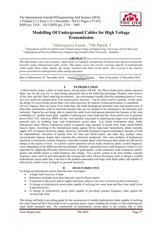
  • 6. Modelling Of Underground Cables For High... www.theijes.com The IJES Page 62 The values of I is computed for various values of using Matlab and the graph plotted. The output of the graph is shown in figure 1.0: Fig1.0 Cable Ampacity vs Ambient Temperature for XLPE with aluminium conductor XLPE insulated cable with copper conductor: For copper conductor, the relationship between the ampacity and the ambient temperature and its plot is shown in figure 2.0: I = Fig 2.0 Graph of Ampacity vs Ambient temperature for XLPE insulated copper conductor cable For Polyvinyl Chloride Insulator: For Aluminium Conductor : The relationship between the Ampacity and the Ambiet temperature and its graph is shown below:I = Graph of Ampacity vs Ambient temperature for PVC with Aluminium conductor Copper conductor with PVC insulation:The relationship and the graph are shown in figure 3.0 I =
  • 7. Modelling Of Underground Cables For High... www.theijes.com The IJES Page 63 Fig 3.0 Graph of ampacity vs ambient temperature for PVC insulation with copper conductor Oil Impregnated Paper dielectric: The relationship between the ampacity and ambient temperature for each of the two different types of conductor using paper dielectric is shown in figure 4.0 Aluminium Conductor: The relationship and the graph is shown below: I = Fig 4.0 Graph of ampacity vs Ambient Temperature for Paper Dielectric using aluminium Copper Conductor: The relationship and the graph for a paper insulated cable for ampacity against ambient temperature is shown in figure 5.0 I = Fig 5.0 Graph of ampacity vs abient temperature for paper insulated copper conductor cable Conductor Temperature : As shown from the Ampacity calculations, the relationship between the Ampacity rating of underground cables and the Conductor temperature for Aluminium and Copper Conductors respectively are; Aluminium: I = where Conductor Temperature The values of I is plotted for various values of and the graph showing this relationship is shownin figure 6.0
  • 8. Modelling Of Underground Cables For High... www.theijes.com The IJES Page 64 Fig 6.0 Graph of Cable Ampacity vs Core temperature with Aluminium conductor For Copper Conductor: The relationship and its graph is shown in figure 7.0 I = Fig 7.0 Graph of Ampacity vs copper conductor core temperature For Dielectric loss: The effect of dielectric losses on Ampacity is studied for XLPE insulation with each of the two conductors i.e. aluminium and copper conductors. The relationship and the plot of Ampacityvs dielectric loss for each of the different dielectric is shown in figure 8.0 and 9.0 respectively FOR ALUMINIUM CONDUCTOR: I = Fig 8.0 Graph of Ampacity vs Dielectric loss for Aluminium Conductor Copper Conductor: The relationship and the graph of Ampacity vs. dielectric loss for a copper conductor XLPE insulated cable is shown below: I =
  • 9. Modelling Of Underground Cables For High... www.theijes.com The IJES Page 65 Fig 9.0 Graph of Ampacity vs Dielectric loss for copper conductor, XLPE insulated cable  TRANSIENT STATE : The insulators are weakened as a result of over voltage surges in transmission lines. This is majorly noticed when XLPE insulated cables are used for underground cabling. This eventually results in cable failure. However ,in ensuring that this failure does no happen, the insulator breakdown as a result of temperature rise should therefore be computed in order to determine the over- voltage ratings of such cables.The rise in core temperature and time duration of over-current should be known to calculate the over-current rating and it depends on their thermal conditions.  SHORT CIRCUIT RATING : According to Jean-Pierre in Nexans publication (2004), Short circuit current in an electrical network are as a result of the accidental connection of one or more phase conductors, either together, or with the ground. There are two types of short circuit currents namely: Symmetrical Short Circuits (3 phase short circuits) where the currents in the three phases form a balanced system. These currents therefore only circulate in the conductor (cores) of the cable.Zero Sequence Short Circuits result from an unsymmetrical i.e. unbalanced current system. Zero sequence currents return via the ground and/ or by the conductors that are electrically parallel to the ground. These conductors are mainly ground conductors, metallic screens connected to the ground at the line termination or ground itself. Under short circuit conditions, the current flowing in the cable is many times the full load value of the current. Heat produced in the conductor is proportional to the square of the current.The safe value of limiting temperature is usually taken as 1200 C. For a maximum continuous operating conductor temperature of 500 C and a permissible temperature rise of 200 C during Short Circuit, the approximate formula may be given as ISC = Where ISC = Short Circuit rms value of the current, A = Cross-sectional Area of the conductor, t = Duration of Short Circuit (seconds), K = A constant (The value of the constant depends on the rise of temperature).If the amount of heat generated in a cable is equal to that dissipated, a thermal equilibrium is reached. For satisfactory operation of the cable, the operating temperature should be lesser than the permissible maximum temperature. In case the amount of heat generated is more than the dissipated, the cable temperature goes on rising till a thermal breakdown occurs when the insulation is damaged. Thus there’s a need for protection of underground cables against Transient Over-Voltages and Short Circuit current.  EFFECTS OF SHORT-CIRCUIT CURRENTS ON EQUIPMENT Thermal effects : Short-circuit currents flowing through conductors of various power system equipment create thermal effects due to heating and excess energy input over time as measured by I2 T.Where Iis short-circuit current magnitude and T, short-circuit current duration. The heat loss from conductors during isalso very low. Generally, both ac and dc components of short-circuit current contribute to thermal heating of conductors.. During the making of high short-circuit currents by inadequately rated circuit-breakers, their contacts may weld together encouraged by a pre striking flashover arc and possibly contact popping.  Mechanical Effects : Short-circuit currents flowing through conductors of various power system equipment create electromagnetic forces and mechanical stresses on underground cables. The electromagnetic forces produced by short-circuit currents in three-core unarmored cables tend to repel the cores from each other and could burst the cable altogether leading to insulation damage if the cores are not adequately bound.
  • 10. Modelling Of Underground Cables For High... www.theijes.com The IJES Page 66  POWER GENERATED IN AN UNDERGROUND CABLE Reactive power is a concept used to describe the background energy movement arising in Alternating Current (AC) system due to production of electric and magnetic fields. These fields store energy which changes through each AC cycle. Reactive power flows can give rise to substantial voltage changes across the system thus it is necessary to maintain reactive power balancesbetween the sources of generation and the point of demand on zonalbasis. Underground cables, when operating at normal system voltage produce strong electric field and so generate reactive power. When current flows through a cable, it produces magnetic fields which absorb reactive power. The reactive power generated by electric field in underground cables is always greater than the reactive power absorbed by the magnetic field. Thus, the underground cable is a net generator of reactive power.Since the single core cable has an earthed metallic sheath, there is an electric field between the conductor core and the sheath. Let the charge on the surface of the conductor be q coulomb per metre length of cable. The electric flux density at a radius x is Dx= C/m2 12 The electric field intensity Ex at a radius x isEx = Dx╱ r  0 = q/2∏ r  0x V/m 13. Where  r is the relative permittivity (dielectric constant) of the cable insulation and  0 = 8.85 x 10⁻¹² F/m.The potential difference between the core and the sheath is V =∫r R Exdx = (q/2∏ r  0)(In ) volts 14 Capacitance between the conductor core and sheath is C = = (2∏ r  0/In ) F/m 15 An underground cable has high capacitance which results in charging current and reactive power. If V is the line to line voltage, the charging current Ic is Ic=2 fCV/ 16 This therefore implies that the 3-phase reactive power is VIc. Applying equation 16 Reactive power = VIc = V (2∏fCV/ [2∏ r  0/In = 4 2 f V2 r  0/[In (R/r)] vars/m 17 The flow of charging current causes heating of the cable. Therefore, the load current capability of the underground cable is decreased (i.e. derating occurs) if the temperature rise is not exceeded. VI RESULTS OF RESEARCH The Steady state Ampacity rating of an underground cable is derived and it is given as:I = Where X = ( T1 + ( 1 +  (T3 + T4)) Y= ( ½ T1 + T3 + T4 ),W = Wd,R = Rac, = ca,, c =Conductor temperaturea =Ambient temperature. Due to the economic implications of underground cable failures, it is important to study the different parameters that directly or indirectly affect the Ampacity rating of an Underground Cable. The following results have therefore been deduced: Ambient Temperature: The research shows that the ambient temperature is inversely proportional to the Ampacity rating of an Underground Cable in the steady state irrespective of the type of conductor (whether copper or Aluminium used).For all the graphs plotted, it is clear that irrespective of the type of insulation, the Ampacity of a copper conductor is always higher than that of an Aluminium conductor. Conductor Temperature: The conductor core temperature is directly proportional to Ampacity of an underground cable. It can further be deduced that, Insulation Resistance. The insulation resistance of a dielectric is inversely proportional to the Ampacity of an Underground Cable. This therefore means that the higher the Ampacity, the lesser the Insulation resistance. Cable Depth In Soil (for direct burial method): The cable depth in soil is inversely proportional to the Ampacity rating of the Underground cable. The higher the depth value is, the lower the Ampacity of the cable. Transient State And Short Circuit State Condition: In the event of a switching over-voltage (transient state) and a short circuit fault ( short circuit condition) the insulator must be able to withstand the rapid temperature rise accompanied by these occurrences without the insulator degrading so as to eliminate that cause of underground cable failure The reactive power generated in underground cables is accompanied by the flow of charging current which causes heating of the underground cable. The insulator should be able to withstand the amount of heat produced without degrading so as not to result in failure of the Underground Cable.
  • 11. Modelling Of Underground Cables For High... www.theijes.com The IJES Page 67 VII CONCLUSION The study of the behaviour of underground cables in the steady, transient and short circuit states gave so much insights into the behaviour of underground cables under these conditions. The knowledge of the main cause of Underground cable failure which is the failure of the dielectric or the insulating material due to excessive heating of the cable was covered. In order to reduce failure rates of underground cables, the design and construction of cables should be such that it operates within acceptable temperature limits during each of the steady, transient and short circuit conditions. Also the effect of the environment (which includes the surrounding soil where the cable is to be laid ). All the various aspects of this research should therefore be considered during the design of cables in order to get the desired output. VIII RECOMMENDATION: Although the cost of installation of underground cable system is very high compared to the equivalent cost of installing an overhead transmission line system, the underground cable has a far higher reliability than the overhead line. The underground cable system also has a lesser failure rates and outages compared to the overhead line system. With the ever growing Nigerian population and the recent intention of the federal government of Nigeria to increase the primary transmission voltage from 330kV to 750 kV, the use of Underground cables for the transmission of this 750 kV will be a good and economical option The use of 750kV in overhead line will pose too much risk to lives and properties as they are exposed to increased radiation. Most importantly, they are also at serious risk of electrocution if the air between the overhead line and the ground is ionized as a result of the extremely high voltage. Alternatively, with the Underground cable system, the failure rates are highly reduced thus far lower outages, they last longer than overhead transmission lines, underground cables can be passed through residential areas without posing any risk to the people and animals living in that area REFERENCES [1] American Electric Power, “Important Factors Affecting Underground Cable Placement of Transmission Facilities”, May 2007. [2] Faruk, A., et al “Computer Assisted Teaching of Underground Power Cables (POWCABGUI) for Graduate Students”, p 1-7, September 2009. [3] Francisco, D.”Calculation of Underground Cable Ampacity”, CYME International T&D, September 2005. [4] Keith, M., “ELEC 5205- High Voltage Engineering”, University of Sydney, March 2008. [5] Johan, E., “Underground Cables in Transmission Networks”. May 2005 [6] Nexans High Voltage Underground Cables, “60-500kV High Voltage Underground Power Cables, XLPE insulated cables”, August 2004. [7] Transpower New Zealand LTD, “Comparison of Reliability of a 400kV Underground Cable with an Overhead Line for a 200km Circuit”, p 1-6, March 2005. [8] Unnur, S., et. Al “Measurement for validation of high voltage Underground Cable Modelling”, p 1-2,March 2009.