SlideShare a Scribd company logo
1 of 11
Download to read offline
Unit IV Telecommunication system
PBX
The acronym PBX (or PABX in Europe) stands for private automatic branch exchange, a device for
switching telephone calls within a building such as an office block or factory. The fundamental principles of
PBX switching are the same as those found in a much larger central office switch, which is used in the
public network to switch telephone traffic from the caller to the person who is being called. The PBX is
essentially a connecting device. When a call comes into the PBX from an outside trunk line, it is either
routed directly to the telephone extension or to a console with human attendant.
The fundamental elements of a digital PBX are shown in Fig. All incoming lines enter some sort of
switching matrix (1). Depending on the number of extensions connected to the PBX, there can be hundred or
even thousands of different switching paths to which the incoming call may be connected. The paths within
the switching matrix are controlled by a central processor (computer (2)). Each extension line must be
constantly scanned for activity (3) and the processor alerted, when activity occurs. The central processor
must be informed when a user wishes to place a call as the telephone is picked up. When the number has
been dialed, the processor must be able to read the required number and make the connection internally or if
it is a call outside PBX, the processor must allocate it an outside line. Similarly, when a caller replaces the
telephone handset after the call is finished, the processor needs to be informed that this extension is now free
to accept further calls. There are also various signals which must be sent down the line, such as busy signals
signals to make the phone ring, on hook/off hook, dialing and so on. The signaling equipment (4) is
controlled as a subset of the central processor. Finally, information about each call, its duration, the number
called, and so on, needs to be gathered for accounting and analysis (5).
GSM Architecture
The figure shows the three main parts that the network architecture can be divided into:
 Mobile Station (MS).
 Base Station Subsystem (BSS).
 Net Subsystem (NS).
The Mobile Station consists of the mobile equipment. Typically a mobile phone. The mobile equipment is
uniquely identified by the International Mobile Equipment Identity (IMEI), which is there to prevent theft.
Furthermore, the MS has to be equipped with a Subscriber Identity Module a so called SIM card. The SIM
card identifies the user to the network using a International Mobile Subscriber Identity (IMSI). The SIM card
can be used in different mobile equipment.
The Base Station Subsystem can be divided into two parts: The Base Transceiver Station (BTS) and the
Base Station Controller (BSC). The BTS houses the radio transceivers that defines a cell. The BSC manages
the radio resources of one or more BTS.
The Network Subsystem consists of the Mobile services Switching Center (MSC) that functions as a normal
switching node of a PSTN (Public Switched Telephone Network) or an ISDN node. With the added
functionality of handling Mobile stations such as: Registration, authentication, location updating, handovers,
and call routing to a roaming subscriber. Furthermore, the Network Subsystem consists of four databases:
The Home Location Register (HLR) that contains all the administrative information of the networks
subscribers, The Visitor Location Register that contains selected administrative information from the HLR
regarding the roaming users in the cells managed by the MSC, The Equipment Identity Register (EIR) and
The Authentication Center provides security and authentication.
GPRS System Architecture
The GPRS is an enhancement over the GSM and adds some nodes in the network to provide the packet
switched services. These network nodes are called GSNs (GPRS Support Nodes) and are responsible for the
routing and delivery of the data packets to and form the MS and external packet data networks (PDN). The
figure 2.2 below shows the architecture of the GPRS system.
The most important network nodes added to the existing GSM networks are:
 SGSN (Serving GPRS Support Node).
 GGSN (Gateway GPRS Support Node).
The serving GPRS support node (SGSN) is responsible for routing the packet switched data to and
from the mobile stations (MS) within its area of responsibility. The main functions of SGSN are packet
routing and transfer, mobile attach and detach procedure (Mobility Management (MM)), location
management, assigning channels and time slots (Logical Link Management (LLM)), authentication and
charging for calls. It stores the location information of the user (like the current location, current VLR) and
user profile (like IMSI addresses used in packet data networks) of registered users in its location register.
The gateway GPRS support node (GGSN) acts as interface between the GPRS backbone and the
external packet data network (PDN). It converts the GPRS packet coming from the SGSN into proper packet
data protocol (PDP) format (i.e. X.25 or IP) before sending to the outside data network. Similarly it converts
the external PDP addresses to the GSM address of the destination user. It sends these packets to proper
SGSN. For this purpose the GGSN stores the current SGSN address of the user and his profile in its location
register. The GGSN also performs the authentication and charging functions. In general there may be a many
to many relationship between the SGSN and GGSN. However a service provider may have only one GGSN
and few SGSNs due to cost constraints. A GGSN proved the interface to several SGSNs to the external
PDN.
UMTS (Universal mobile telecommunication services)
UMTS offers tele-services (like speech or SMS) and bearer services, which provide the ability for
information transfer between access points. It is possible to negotiate and renegotiate the characteristics of a
bearer service at session or connection establishment and during ongoing session or connection. Both
connection oriented and connectionless services are offered for point to-Point and Point-to-Multipoint
communication.
Bearer services have different QoS parameters for maximum transfer delay, delay variation and bit error
rate. Offered data rate targets are:
 144 kbits/s satellite and rural outdoor
 384 kbits/s urban outdoor
 2048 kbits/s indoor and low range outdoor
UMTS network services have different QoS classes for four types of traffic:
 Conversational class (voice, videotelephony, video gaming)
 Streaming class (multimedia, video on demand, webcast)
 Interactive class (web browsing, network gaming, database access)
 Background class (email, SMS, downloading)
UMTS will also have a Virtual Home Environment (VHE). It is a concept for personal service environment
portability across network boundaries and between terminals. Personal service environment means that users
are consistently presented with the same personalized features, User Interface customization and services in
whatever network or terminal, wherever the user may be located. UMTS also has improved network security
and location based services.
3. UMTS Architecture
A UMTS network consist of three interacting domains; Core Network (CN), UMTS Terrestrial Radio Access Network
(UTRAN) and User Equipment (UE). The main function of the core network is to provide switching, routing and
transit for user traffic. Core network also contains the databases and network management functions.
The basic Core Network architecture for UMTS is based on GSM network with GPRS. All equipment has to
be modified for UMTS operation and services. The UTRAN provides the air interface access method for User
Equipment. Base Station is referred as Node-B and control equipment for Node-B's is called Radio Network Controller
(RNC).
 UMTS systems (including satellite)  Public Land Mobile Network (PLMN)
 MSC/VLR or SGSN  Location Area  Routing Area (PS domain)
 UTRAN Registration Area (PS domain)  Cell  Sub cell
DECT Functional Concept
The DECT subsystem is a microcellular
or picocellular cordless telephone
system that may be integrated with or
connected to a Private Automatic
Branch Exchange (PABX) or to the
Public Switched Telephone Network
(PSTN). A DECT system always
consists of the following five functional
entities as shown in Figure
Portable Handset (PH): This is the
mobile handset or the terminal. In
addition, cordless terminal adapters
(CTAs) may be used to provide fax or
video communications.
Radio Fixed Part (RFP): This supports the physical layer of the DECT common air interface. Every RFP
covers one cell in the microcellular system. The radio transmission between RFP and the portable unit uses
multi carrier TDM A. A full duplex operation is achieved using time division duplexing (TDD).
Cordless Controller (CC or Cluster Controller): This handles the MAC, DLC, and network layers for one
or a cluster of RFPs and thus forms the central control unit for the DECT equipment. Speech coding is done
in the CC using 32 kbps ADPCM.
Network-specific Interface Unit : This supports the call completion facility in a multihandset environment.
The interface recommended by the CCITT is the G.732 based on ISDN protocols.
Supplementary Services: This provides centralized authentication and billing when DFCT is used to
provide telenoint services and mobility management when DECT is used in multilocation PAPX network.
Wi-Fi (wireless fidelity)
Wi-Fi is a popular wireless networking
technology. Wi-Fi stands for “wireless
fidelity”. The Wi-Fi was invented by NCR
corporation/AT&T in Netherlands in 1991.
By using this technology we can exchange the
information between two or more devices.
Wi-Fi has been developed for mobile
computing devices, such has laptops, but it is
now extensively using for mobile applications
and consumer electronics like televisions,
DVD players and digital cameras. There should be two possibilities in communicating with the Wi-Fi
connection that may be through access point to the client connection or client to client connection. Wi-Fi is a
one type of wireless technology. It is commonly called as wireless LAN (local area network). Wi-Fi allows
local area networks to operate without cable and wiring. It is making popular choice for home and business
networks. A computer’s wireless adaptor transfers the data into a radio signal and transfers the data into
antenna for users.
The following list summarizes some of the benefits of a Wi-Fi network. •
Wireless Ethernet: Wi-Fi is an Ethernet replacement. Wi-Fi and Ethernet, both IEEE 802 networks, share
some core elements.
Extended Access: The absence of wires and cables extends access to places where wires and cables cannot
go or where it is too expensive for them to go.
Cost Reduction: As mentioned above, the absence of wires and cables brings down cost. This is
accomplished by a combination of factors, the relatively low cost of wireless routers, no need for trenching,
drilling and other methods that may be necessary to make physical connections.
Mobility: Wires tie you down to one location. Going wireless means you have the freedom to change your
location without losing your connection. Flexibility: Extended access, cost reductions, and mobility create
opportunities for new applications as well as the possibility of creative new solutions for legacy applications.
Blue tooth
Bluetooth works in the Industrial, Scientific and Medical (ISM) band from 2400-2483.5 MHz (including
guard bands) from mobile as well as fixed devices by creation of PANs with high security level. Several
devices can be connected by using this technology, overcoming synchronization problems. Bluetooth uses
technology called Frequency-Hopping Spread Spectrum (FHSS) which is a radio technology. The data to be
transmitted is first divided into packets and then each packet is made to transmit on one among the
designated 79 Bluetooth channels. Bandwidth of each channel is 1 MHz. The very first channel starts at
frequency of 2402 MHz and goes up to 2480 MHz in steps of 1 MHz. Usually it performs 1600 hops per
second
Bluetooth is a packet-based protocol which is having a master-slave
structure. In a piconet up to 7 slaves can be communicated by one
master. Timing on the network can be controlled by Bluetooth by
designating one device as a slave and the other as a master. The unit
which initiates communication link is master and the other
participants are slaves. After breakdown of link, the designations of
master/slave no longer apply. Fact is that, every Bluetooth device is
having both master and slave hardware. The network is called as
piconet, which means a small network. When number of slaves is
only one, then link is called as point-to-point. In a point-to-multipoint configuration up to seven active slaves can be
controlled by a master
 When a device want to connect to another
device via Bleutooth it first enters an inquiry
substate. This allows it to scan, or inquire, for
detectable devices. Every device that is detectable
enters inquiry scan substate once per given time.
When the inquiry scan substate registers an
inquiry from a master device it enters the inquiry
response substate and answers with an inquiry
response message which includes the device’s
address and clock.
 The master will receive such a message
from all detectable devices in range. Therefore the
wanted device is usually manually detected. When
this is done the device enters paging substate. If
 the other device is set to connect to other
devices it enters page scan substate once per given
time.
 When the slave receives a page packet from the master it responds with a page response packet.
Upon receiving the master shall send several synchronization packets to adjust synchronize the frequency
hopping and clock in both devices. When this is done the devices go into connection state.
 In transmission state the devices take on any of the four following states: active sniff, hold or park
state. Active state means that both devices are connected constantly and are always listening transmitting or
receiving on the channel. In sniff state the slave stops scanning for the masters packets on all channels but
listens in on specific channels on specific times, saving energy. In hold mode the slave does not listen to
channels connecting multiple devices in the piconet. It goes into a low power sleep mode allowing the
channel to be used for paging and scanning. When in park mode the slave is not an active part of the network
or piconet. Its Bluetooth address switches from active member address to passive member address
FAX
The essential parts of a fax system are the transmitting devices that translate the graphic material into
electrical impulses according to a set pattern, and a synchronized receiving device that retranslates these
impulses and prints that. In a typical system, the fax scanner consists of a rotating cylinder, a source
projecting a narrow beam of light and a photoelectric cell. The copy to be transmitted is wrapped around the
cylinder and is scanned by the light beam, which moves along the cylinder as it revolves.
The output of the photoelectric cell is amplified
and transmitted to the receiving end, where a
similar cylinder, covered with specially
impregnated paper, revolves in synchronism
with the transmitting cylinder. A light of varying
intensity moves along the rotation cylinder and
darkens the paper by chemically reproducing the
pattern of the original. When the fax is done, it
pops out as a blue print of what the other person
sent.
1. To send a fax, you feed the page into the input slot and it's pulled in between several pairs of rollers.
Larger fax machines have built-in document feeders that automatically feed in multiple pages from a
stack, so you don't have to stand at the machine feeding in pages one at a time.
2. As the paper moves down, a bright light shines onto it. White areas of the page reflect a lot of light;
black areas reflect little or none.
3. The light reflects off the page into a light-detecting CCD (charged-coupled device)
4. The CCD turns the analog pattern
of black and white areas on the
page into a numeric (digital) pattern
of binary zeros and ones and passes
the information to an electronic
circuit.
5. The circuit sends the digital
information down the telephone
line to the fax machine at the
receiving end.
6. When you receive a fax, the same
circuit takes incoming digital
information from the phone line
and routes it to a built-in printer.
7. In a typical personal fax machine,
paper is pulled from a large roll
inside the machine. (In a larger
office fax machine, it usually comes from a plain-paper hopper, similar to the one in a laser printer.)
8. The thermal (heat-based) printer, operated by the circuit, reproduces the incoming fax on the paper as
it moves past.
9. An automatic blade cuts the page and the printed fax emerges from the output slot.
IMT 2000
IMT 2000 (International Mobile Telecommunications for the year 2000) is a worldwide set of requirements for a
family of standards for the 3rd
generation of mobile communications. The IMT-2000 "umbrella specifications" are
developed by the International Telecommunicatons Union (ITU). Originally it was the intention to have only one truly
global standard but that turned out to be impossible. IMT-2000 should provide worldwide mobile broadband
multimedia services via a single global frequency band. The frequency range should be around 2000 MHz.
In the umbrella specification a number of characteristics are defined which the underying technologies
should meet. The main characteristics are:
 Worldwide usage,
integration of satellite and terrestrial systems to provide global coverage;
 Used for all radio environments,
(LAN, cordless, cellular, satellite);
 Wide range of telecommunications services,
(voice, data, multimedia, internet);
 Support both packet-switched (PS) and circuit-switched (CS) data transmission;
 Offer high data rates up to 2 Mbps,
o 144 kbps for high mobility,
o 384 kbps with restricted mobility and,
o 2 Mbps in an indoor office environment;
 Offer high spectrum efficiency;
Wireless Local Loop
Local loop is a circuit line from a subscriber’s phone to the local central office (LCO). But the
implementation of local loop of wires is risky for the operators, especially in rural and remote areas due to
less number of users and increased cost of installation. Hence, the solution for it is the usage of wireless
local loop (WLL) which uses wireless links rather than copper wires to connect subscribers to the local
central office.
WLL components:
1. PSTN:
It is Public Switched Telephone Network which is a circuit switched network. It is a collection of
world’s interconnected circuit switched telephone networks.
2. Switch Function:
Switch Function switches the PSTN among various WANUs.
3. WANU:
It is short for Wireless Access Network Unit. It is present at the local exchange office. All local WASUs
are connected to it. Its functions includes: Authentication, Operation & maintenance, Routing,
Transceiving voice and data. It consists of following sub-components:
 Transceiver: It transmits/receives data.
 WLL Controller: It controls the wireless local loop component with WASU.
 AM: It is short for Access Manager. It is responsible for authentication.
 HLR: It is short for Home Location Register. It stores the details of all local WASUs.
2. WASU:
It is short for Wireless Access Subscriber Units. It is present at the house of the subscriber. It connects
the subscriber to WANU and the power supply for it is provided locally.
Advantages of WLL:
 It eliminates the first mile or last mile construction of the network connection.
 Low cost due to no use of conventional copper wires.
 Much more secure due to digital encryption techniques used in wireless communication.
 Highly scalable as it doesn’t require the installation of more wires for scaling it.
Features of WLL:
 Internet connection via modem
 Data service
 Voice service
 Fax service

More Related Content

What's hot

EC8004 WIRELESS NETWORKS UNIT 5 - IMS
EC8004 WIRELESS NETWORKS UNIT 5 - IMS EC8004 WIRELESS NETWORKS UNIT 5 - IMS
EC8004 WIRELESS NETWORKS UNIT 5 - IMS HemalathaR31
 
Ewsd
EwsdEwsd
EwsdPTCL
 
presentation on gsm architecture and fixed assignment
presentation on gsm architecture and fixed assignmentpresentation on gsm architecture and fixed assignment
presentation on gsm architecture and fixed assignmentFabiha Ain
 
EC8004 WIRELESS NETWORKS UNIT 3 CORE NETWORK
EC8004 WIRELESS NETWORKS UNIT 3 CORE NETWORKEC8004 WIRELESS NETWORKS UNIT 3 CORE NETWORK
EC8004 WIRELESS NETWORKS UNIT 3 CORE NETWORKHemalathaR31
 
Global system for mobile
Global system for mobileGlobal system for mobile
Global system for mobilePartha Bhunia
 
Global system for mobile communication(GSM)
Global system for mobile communication(GSM)Global system for mobile communication(GSM)
Global system for mobile communication(GSM)Jay Nagar
 
Presentation SIM CARD (GSM)
Presentation SIM CARD (GSM)Presentation SIM CARD (GSM)
Presentation SIM CARD (GSM)Ekansh Agarwal
 
IT8602 Mobile Communication Unit II
IT8602 Mobile Communication   Unit II IT8602 Mobile Communication   Unit II
IT8602 Mobile Communication Unit II pkaviya
 
Unit 5 : wireless communication : GSM System operations
Unit 5 : wireless communication : GSM System operationsUnit 5 : wireless communication : GSM System operations
Unit 5 : wireless communication : GSM System operationsAshutha K
 

What's hot (20)

EC8004 WIRELESS NETWORKS UNIT 5 - IMS
EC8004 WIRELESS NETWORKS UNIT 5 - IMS EC8004 WIRELESS NETWORKS UNIT 5 - IMS
EC8004 WIRELESS NETWORKS UNIT 5 - IMS
 
Ewsd
EwsdEwsd
Ewsd
 
presentation on gsm architecture and fixed assignment
presentation on gsm architecture and fixed assignmentpresentation on gsm architecture and fixed assignment
presentation on gsm architecture and fixed assignment
 
EC8004 WIRELESS NETWORKS UNIT 3 CORE NETWORK
EC8004 WIRELESS NETWORKS UNIT 3 CORE NETWORKEC8004 WIRELESS NETWORKS UNIT 3 CORE NETWORK
EC8004 WIRELESS NETWORKS UNIT 3 CORE NETWORK
 
Global system for mobile
Global system for mobileGlobal system for mobile
Global system for mobile
 
Global system for mobile communication(GSM)
Global system for mobile communication(GSM)Global system for mobile communication(GSM)
Global system for mobile communication(GSM)
 
Switching systems lecture7
Switching  systems lecture7Switching  systems lecture7
Switching systems lecture7
 
It2402 mobile communication unit3
It2402 mobile communication unit3It2402 mobile communication unit3
It2402 mobile communication unit3
 
Switching systems lecture6
Switching  systems lecture6Switching  systems lecture6
Switching systems lecture6
 
Unit 2
Unit 2Unit 2
Unit 2
 
CS8601 MOBILE COMPUTING
CS8601	MOBILE COMPUTING CS8601	MOBILE COMPUTING
CS8601 MOBILE COMPUTING
 
It2402 mobile communication unit2
It2402 mobile communication unit2It2402 mobile communication unit2
It2402 mobile communication unit2
 
Digital network lecturer5
Digital network  lecturer5Digital network  lecturer5
Digital network lecturer5
 
Codec
CodecCodec
Codec
 
Gprs architecture ppt
Gprs architecture pptGprs architecture ppt
Gprs architecture ppt
 
Presentation SIM CARD (GSM)
Presentation SIM CARD (GSM)Presentation SIM CARD (GSM)
Presentation SIM CARD (GSM)
 
IT8602 Mobile Communication Unit II
IT8602 Mobile Communication   Unit II IT8602 Mobile Communication   Unit II
IT8602 Mobile Communication Unit II
 
Umts chap5
Umts chap5Umts chap5
Umts chap5
 
Unit 5 : wireless communication : GSM System operations
Unit 5 : wireless communication : GSM System operationsUnit 5 : wireless communication : GSM System operations
Unit 5 : wireless communication : GSM System operations
 
Ch6
Ch6Ch6
Ch6
 

Similar to telecommunication system

Similar to telecommunication system (20)

GSM, GPRS and UMTS: easy handbook
GSM, GPRS and UMTS: easy handbookGSM, GPRS and UMTS: easy handbook
GSM, GPRS and UMTS: easy handbook
 
Celluler telephone 2
Celluler telephone 2Celluler telephone 2
Celluler telephone 2
 
2g,3g,4g, technology Dialog axiata
2g,3g,4g, technology Dialog axiata2g,3g,4g, technology Dialog axiata
2g,3g,4g, technology Dialog axiata
 
mobile computing and ad hoc network
mobile computing and ad hoc networkmobile computing and ad hoc network
mobile computing and ad hoc network
 
MC-U2NOTES.pdf
MC-U2NOTES.pdfMC-U2NOTES.pdf
MC-U2NOTES.pdf
 
Gsm is
Gsm isGsm is
Gsm is
 
E4-E5_CM_08_3G MOBILE NW.ppt
E4-E5_CM_08_3G MOBILE NW.pptE4-E5_CM_08_3G MOBILE NW.ppt
E4-E5_CM_08_3G MOBILE NW.ppt
 
GSM & GPRS ARCHITECTURE
GSM & GPRS ARCHITECTUREGSM & GPRS ARCHITECTURE
GSM & GPRS ARCHITECTURE
 
G second generation network
G second generation networkG second generation network
G second generation network
 
6_2019_04_17!05_57_06_AM.pptx
6_2019_04_17!05_57_06_AM.pptx6_2019_04_17!05_57_06_AM.pptx
6_2019_04_17!05_57_06_AM.pptx
 
IT6601 MOBILE COMPUTING
IT6601 MOBILE COMPUTINGIT6601 MOBILE COMPUTING
IT6601 MOBILE COMPUTING
 
Ch5
Ch5Ch5
Ch5
 
UMTS core network and its evolution
UMTS core network and its evolutionUMTS core network and its evolution
UMTS core network and its evolution
 
Wireless module 2 notes vtu 18ec81 GSM Module
Wireless module 2 notes vtu 18ec81 GSM ModuleWireless module 2 notes vtu 18ec81 GSM Module
Wireless module 2 notes vtu 18ec81 GSM Module
 
Chapter 3 Telecom Sys.pptx
Chapter 3  Telecom Sys.pptxChapter 3  Telecom Sys.pptx
Chapter 3 Telecom Sys.pptx
 
Pawan..bsnl
Pawan..bsnlPawan..bsnl
Pawan..bsnl
 
Gsm overview
Gsm overviewGsm overview
Gsm overview
 
GSM
GSMGSM
GSM
 
It6601 mobile computing unit 3
It6601 mobile computing unit 3It6601 mobile computing unit 3
It6601 mobile computing unit 3
 
Gsm1
Gsm1Gsm1
Gsm1
 

More from Tamilarasan N

PHASE LOCKED LOOP AND TIMER
PHASE LOCKED LOOP AND TIMERPHASE LOCKED LOOP AND TIMER
PHASE LOCKED LOOP AND TIMERTamilarasan N
 
Analog IC Application
Analog IC ApplicationAnalog IC Application
Analog IC ApplicationTamilarasan N
 
OPERATIONAL AMPLIFIERS
OPERATIONAL AMPLIFIERSOPERATIONAL AMPLIFIERS
OPERATIONAL AMPLIFIERSTamilarasan N
 
Digital integrated circuits
Digital integrated circuitsDigital integrated circuits
Digital integrated circuitsTamilarasan N
 
Telecommunication Systems
Telecommunication SystemsTelecommunication Systems
Telecommunication SystemsTamilarasan N
 
Optical recording system
Optical recording systemOptical recording system
Optical recording systemTamilarasan N
 
Television standards and systems
Television standards and systemsTelevision standards and systems
Television standards and systemsTamilarasan N
 
LOUD SPEAKER AND MICROPHONE
LOUD SPEAKER AND MICROPHONELOUD SPEAKER AND MICROPHONE
LOUD SPEAKER AND MICROPHONETamilarasan N
 
Performance of the MIMO-MC-CDMA System with MMSE Equalization
Performance of the MIMO-MC-CDMA System with MMSE EqualizationPerformance of the MIMO-MC-CDMA System with MMSE Equalization
Performance of the MIMO-MC-CDMA System with MMSE EqualizationTamilarasan N
 
PERFORMANCE OF MIMO MC-CDMA SYSTEM WITH CHANNEL ESTIMATION AND MMSE EQUALIZATION
PERFORMANCE OF MIMO MC-CDMA SYSTEM WITH CHANNEL ESTIMATION AND MMSE EQUALIZATIONPERFORMANCE OF MIMO MC-CDMA SYSTEM WITH CHANNEL ESTIMATION AND MMSE EQUALIZATION
PERFORMANCE OF MIMO MC-CDMA SYSTEM WITH CHANNEL ESTIMATION AND MMSE EQUALIZATIONTamilarasan N
 
Mmse partially connected hybrid beam forming in mimo ofdm
Mmse partially connected hybrid beam forming in mimo ofdmMmse partially connected hybrid beam forming in mimo ofdm
Mmse partially connected hybrid beam forming in mimo ofdmTamilarasan N
 
Hybrid Adaptive Channel Estimation Technique in Time and Frequency Domain for...
Hybrid Adaptive Channel Estimation Technique in Time and Frequency Domain for...Hybrid Adaptive Channel Estimation Technique in Time and Frequency Domain for...
Hybrid Adaptive Channel Estimation Technique in Time and Frequency Domain for...Tamilarasan N
 
Automated brain tumor detection and segmentation from mri images using adapti...
Automated brain tumor detection and segmentation from mri images using adapti...Automated brain tumor detection and segmentation from mri images using adapti...
Automated brain tumor detection and segmentation from mri images using adapti...Tamilarasan N
 
Performance improvement of mimo mc cdma system using equalization, beamformin...
Performance improvement of mimo mc cdma system using equalization, beamformin...Performance improvement of mimo mc cdma system using equalization, beamformin...
Performance improvement of mimo mc cdma system using equalization, beamformin...Tamilarasan N
 
Performance improvement of mimo mc cdma system using relay and itbf
Performance improvement of mimo mc  cdma system using relay and itbfPerformance improvement of mimo mc  cdma system using relay and itbf
Performance improvement of mimo mc cdma system using relay and itbfTamilarasan N
 

More from Tamilarasan N (16)

PHASE LOCKED LOOP AND TIMER
PHASE LOCKED LOOP AND TIMERPHASE LOCKED LOOP AND TIMER
PHASE LOCKED LOOP AND TIMER
 
Analog IC Application
Analog IC ApplicationAnalog IC Application
Analog IC Application
 
OPERATIONAL AMPLIFIERS
OPERATIONAL AMPLIFIERSOPERATIONAL AMPLIFIERS
OPERATIONAL AMPLIFIERS
 
Digital integrated circuits
Digital integrated circuitsDigital integrated circuits
Digital integrated circuits
 
Home appliances
Home appliancesHome appliances
Home appliances
 
Telecommunication Systems
Telecommunication SystemsTelecommunication Systems
Telecommunication Systems
 
Optical recording system
Optical recording systemOptical recording system
Optical recording system
 
Television standards and systems
Television standards and systemsTelevision standards and systems
Television standards and systems
 
LOUD SPEAKER AND MICROPHONE
LOUD SPEAKER AND MICROPHONELOUD SPEAKER AND MICROPHONE
LOUD SPEAKER AND MICROPHONE
 
Performance of the MIMO-MC-CDMA System with MMSE Equalization
Performance of the MIMO-MC-CDMA System with MMSE EqualizationPerformance of the MIMO-MC-CDMA System with MMSE Equalization
Performance of the MIMO-MC-CDMA System with MMSE Equalization
 
PERFORMANCE OF MIMO MC-CDMA SYSTEM WITH CHANNEL ESTIMATION AND MMSE EQUALIZATION
PERFORMANCE OF MIMO MC-CDMA SYSTEM WITH CHANNEL ESTIMATION AND MMSE EQUALIZATIONPERFORMANCE OF MIMO MC-CDMA SYSTEM WITH CHANNEL ESTIMATION AND MMSE EQUALIZATION
PERFORMANCE OF MIMO MC-CDMA SYSTEM WITH CHANNEL ESTIMATION AND MMSE EQUALIZATION
 
Mmse partially connected hybrid beam forming in mimo ofdm
Mmse partially connected hybrid beam forming in mimo ofdmMmse partially connected hybrid beam forming in mimo ofdm
Mmse partially connected hybrid beam forming in mimo ofdm
 
Hybrid Adaptive Channel Estimation Technique in Time and Frequency Domain for...
Hybrid Adaptive Channel Estimation Technique in Time and Frequency Domain for...Hybrid Adaptive Channel Estimation Technique in Time and Frequency Domain for...
Hybrid Adaptive Channel Estimation Technique in Time and Frequency Domain for...
 
Automated brain tumor detection and segmentation from mri images using adapti...
Automated brain tumor detection and segmentation from mri images using adapti...Automated brain tumor detection and segmentation from mri images using adapti...
Automated brain tumor detection and segmentation from mri images using adapti...
 
Performance improvement of mimo mc cdma system using equalization, beamformin...
Performance improvement of mimo mc cdma system using equalization, beamformin...Performance improvement of mimo mc cdma system using equalization, beamformin...
Performance improvement of mimo mc cdma system using equalization, beamformin...
 
Performance improvement of mimo mc cdma system using relay and itbf
Performance improvement of mimo mc  cdma system using relay and itbfPerformance improvement of mimo mc  cdma system using relay and itbf
Performance improvement of mimo mc cdma system using relay and itbf
 

Recently uploaded

HARDNESS, FRACTURE TOUGHNESS AND STRENGTH OF CERAMICS
HARDNESS, FRACTURE TOUGHNESS AND STRENGTH OF CERAMICSHARDNESS, FRACTURE TOUGHNESS AND STRENGTH OF CERAMICS
HARDNESS, FRACTURE TOUGHNESS AND STRENGTH OF CERAMICSRajkumarAkumalla
 
VIP Call Girls Service Kondapur Hyderabad Call +91-8250192130
VIP Call Girls Service Kondapur Hyderabad Call +91-8250192130VIP Call Girls Service Kondapur Hyderabad Call +91-8250192130
VIP Call Girls Service Kondapur Hyderabad Call +91-8250192130Suhani Kapoor
 
Call Girls in Nagpur Suman Call 7001035870 Meet With Nagpur Escorts
Call Girls in Nagpur Suman Call 7001035870 Meet With Nagpur EscortsCall Girls in Nagpur Suman Call 7001035870 Meet With Nagpur Escorts
Call Girls in Nagpur Suman Call 7001035870 Meet With Nagpur EscortsCall Girls in Nagpur High Profile
 
IVE Industry Focused Event - Defence Sector 2024
IVE Industry Focused Event - Defence Sector 2024IVE Industry Focused Event - Defence Sector 2024
IVE Industry Focused Event - Defence Sector 2024Mark Billinghurst
 
(PRIYA) Rajgurunagar Call Girls Just Call 7001035870 [ Cash on Delivery ] Pun...
(PRIYA) Rajgurunagar Call Girls Just Call 7001035870 [ Cash on Delivery ] Pun...(PRIYA) Rajgurunagar Call Girls Just Call 7001035870 [ Cash on Delivery ] Pun...
(PRIYA) Rajgurunagar Call Girls Just Call 7001035870 [ Cash on Delivery ] Pun...ranjana rawat
 
High Profile Call Girls Nashik Megha 7001305949 Independent Escort Service Na...
High Profile Call Girls Nashik Megha 7001305949 Independent Escort Service Na...High Profile Call Girls Nashik Megha 7001305949 Independent Escort Service Na...
High Profile Call Girls Nashik Megha 7001305949 Independent Escort Service Na...Call Girls in Nagpur High Profile
 
(RIA) Call Girls Bhosari ( 7001035870 ) HI-Fi Pune Escorts Service
(RIA) Call Girls Bhosari ( 7001035870 ) HI-Fi Pune Escorts Service(RIA) Call Girls Bhosari ( 7001035870 ) HI-Fi Pune Escorts Service
(RIA) Call Girls Bhosari ( 7001035870 ) HI-Fi Pune Escorts Serviceranjana rawat
 
Sheet Pile Wall Design and Construction: A Practical Guide for Civil Engineer...
Sheet Pile Wall Design and Construction: A Practical Guide for Civil Engineer...Sheet Pile Wall Design and Construction: A Practical Guide for Civil Engineer...
Sheet Pile Wall Design and Construction: A Practical Guide for Civil Engineer...Dr.Costas Sachpazis
 
Introduction to IEEE STANDARDS and its different types.pptx
Introduction to IEEE STANDARDS and its different types.pptxIntroduction to IEEE STANDARDS and its different types.pptx
Introduction to IEEE STANDARDS and its different types.pptxupamatechverse
 
Introduction and different types of Ethernet.pptx
Introduction and different types of Ethernet.pptxIntroduction and different types of Ethernet.pptx
Introduction and different types of Ethernet.pptxupamatechverse
 
High Profile Call Girls Nagpur Meera Call 7001035870 Meet With Nagpur Escorts
High Profile Call Girls Nagpur Meera Call 7001035870 Meet With Nagpur EscortsHigh Profile Call Girls Nagpur Meera Call 7001035870 Meet With Nagpur Escorts
High Profile Call Girls Nagpur Meera Call 7001035870 Meet With Nagpur EscortsCall Girls in Nagpur High Profile
 
APPLICATIONS-AC/DC DRIVES-OPERATING CHARACTERISTICS
APPLICATIONS-AC/DC DRIVES-OPERATING CHARACTERISTICSAPPLICATIONS-AC/DC DRIVES-OPERATING CHARACTERISTICS
APPLICATIONS-AC/DC DRIVES-OPERATING CHARACTERISTICSKurinjimalarL3
 
Decoding Kotlin - Your guide to solving the mysterious in Kotlin.pptx
Decoding Kotlin - Your guide to solving the mysterious in Kotlin.pptxDecoding Kotlin - Your guide to solving the mysterious in Kotlin.pptx
Decoding Kotlin - Your guide to solving the mysterious in Kotlin.pptxJoão Esperancinha
 
College Call Girls Nashik Nehal 7001305949 Independent Escort Service Nashik
College Call Girls Nashik Nehal 7001305949 Independent Escort Service NashikCollege Call Girls Nashik Nehal 7001305949 Independent Escort Service Nashik
College Call Girls Nashik Nehal 7001305949 Independent Escort Service NashikCall Girls in Nagpur High Profile
 
Current Transformer Drawing and GTP for MSETCL
Current Transformer Drawing and GTP for MSETCLCurrent Transformer Drawing and GTP for MSETCL
Current Transformer Drawing and GTP for MSETCLDeelipZope
 
Architect Hassan Khalil Portfolio for 2024
Architect Hassan Khalil Portfolio for 2024Architect Hassan Khalil Portfolio for 2024
Architect Hassan Khalil Portfolio for 2024hassan khalil
 
Structural Analysis and Design of Foundations: A Comprehensive Handbook for S...
Structural Analysis and Design of Foundations: A Comprehensive Handbook for S...Structural Analysis and Design of Foundations: A Comprehensive Handbook for S...
Structural Analysis and Design of Foundations: A Comprehensive Handbook for S...Dr.Costas Sachpazis
 
(ANJALI) Dange Chowk Call Girls Just Call 7001035870 [ Cash on Delivery ] Pun...
(ANJALI) Dange Chowk Call Girls Just Call 7001035870 [ Cash on Delivery ] Pun...(ANJALI) Dange Chowk Call Girls Just Call 7001035870 [ Cash on Delivery ] Pun...
(ANJALI) Dange Chowk Call Girls Just Call 7001035870 [ Cash on Delivery ] Pun...ranjana rawat
 
GDSC ASEB Gen AI study jams presentation
GDSC ASEB Gen AI study jams presentationGDSC ASEB Gen AI study jams presentation
GDSC ASEB Gen AI study jams presentationGDSCAESB
 

Recently uploaded (20)

Call Us -/9953056974- Call Girls In Vikaspuri-/- Delhi NCR
Call Us -/9953056974- Call Girls In Vikaspuri-/- Delhi NCRCall Us -/9953056974- Call Girls In Vikaspuri-/- Delhi NCR
Call Us -/9953056974- Call Girls In Vikaspuri-/- Delhi NCR
 
HARDNESS, FRACTURE TOUGHNESS AND STRENGTH OF CERAMICS
HARDNESS, FRACTURE TOUGHNESS AND STRENGTH OF CERAMICSHARDNESS, FRACTURE TOUGHNESS AND STRENGTH OF CERAMICS
HARDNESS, FRACTURE TOUGHNESS AND STRENGTH OF CERAMICS
 
VIP Call Girls Service Kondapur Hyderabad Call +91-8250192130
VIP Call Girls Service Kondapur Hyderabad Call +91-8250192130VIP Call Girls Service Kondapur Hyderabad Call +91-8250192130
VIP Call Girls Service Kondapur Hyderabad Call +91-8250192130
 
Call Girls in Nagpur Suman Call 7001035870 Meet With Nagpur Escorts
Call Girls in Nagpur Suman Call 7001035870 Meet With Nagpur EscortsCall Girls in Nagpur Suman Call 7001035870 Meet With Nagpur Escorts
Call Girls in Nagpur Suman Call 7001035870 Meet With Nagpur Escorts
 
IVE Industry Focused Event - Defence Sector 2024
IVE Industry Focused Event - Defence Sector 2024IVE Industry Focused Event - Defence Sector 2024
IVE Industry Focused Event - Defence Sector 2024
 
(PRIYA) Rajgurunagar Call Girls Just Call 7001035870 [ Cash on Delivery ] Pun...
(PRIYA) Rajgurunagar Call Girls Just Call 7001035870 [ Cash on Delivery ] Pun...(PRIYA) Rajgurunagar Call Girls Just Call 7001035870 [ Cash on Delivery ] Pun...
(PRIYA) Rajgurunagar Call Girls Just Call 7001035870 [ Cash on Delivery ] Pun...
 
High Profile Call Girls Nashik Megha 7001305949 Independent Escort Service Na...
High Profile Call Girls Nashik Megha 7001305949 Independent Escort Service Na...High Profile Call Girls Nashik Megha 7001305949 Independent Escort Service Na...
High Profile Call Girls Nashik Megha 7001305949 Independent Escort Service Na...
 
(RIA) Call Girls Bhosari ( 7001035870 ) HI-Fi Pune Escorts Service
(RIA) Call Girls Bhosari ( 7001035870 ) HI-Fi Pune Escorts Service(RIA) Call Girls Bhosari ( 7001035870 ) HI-Fi Pune Escorts Service
(RIA) Call Girls Bhosari ( 7001035870 ) HI-Fi Pune Escorts Service
 
Sheet Pile Wall Design and Construction: A Practical Guide for Civil Engineer...
Sheet Pile Wall Design and Construction: A Practical Guide for Civil Engineer...Sheet Pile Wall Design and Construction: A Practical Guide for Civil Engineer...
Sheet Pile Wall Design and Construction: A Practical Guide for Civil Engineer...
 
Introduction to IEEE STANDARDS and its different types.pptx
Introduction to IEEE STANDARDS and its different types.pptxIntroduction to IEEE STANDARDS and its different types.pptx
Introduction to IEEE STANDARDS and its different types.pptx
 
Introduction and different types of Ethernet.pptx
Introduction and different types of Ethernet.pptxIntroduction and different types of Ethernet.pptx
Introduction and different types of Ethernet.pptx
 
High Profile Call Girls Nagpur Meera Call 7001035870 Meet With Nagpur Escorts
High Profile Call Girls Nagpur Meera Call 7001035870 Meet With Nagpur EscortsHigh Profile Call Girls Nagpur Meera Call 7001035870 Meet With Nagpur Escorts
High Profile Call Girls Nagpur Meera Call 7001035870 Meet With Nagpur Escorts
 
APPLICATIONS-AC/DC DRIVES-OPERATING CHARACTERISTICS
APPLICATIONS-AC/DC DRIVES-OPERATING CHARACTERISTICSAPPLICATIONS-AC/DC DRIVES-OPERATING CHARACTERISTICS
APPLICATIONS-AC/DC DRIVES-OPERATING CHARACTERISTICS
 
Decoding Kotlin - Your guide to solving the mysterious in Kotlin.pptx
Decoding Kotlin - Your guide to solving the mysterious in Kotlin.pptxDecoding Kotlin - Your guide to solving the mysterious in Kotlin.pptx
Decoding Kotlin - Your guide to solving the mysterious in Kotlin.pptx
 
College Call Girls Nashik Nehal 7001305949 Independent Escort Service Nashik
College Call Girls Nashik Nehal 7001305949 Independent Escort Service NashikCollege Call Girls Nashik Nehal 7001305949 Independent Escort Service Nashik
College Call Girls Nashik Nehal 7001305949 Independent Escort Service Nashik
 
Current Transformer Drawing and GTP for MSETCL
Current Transformer Drawing and GTP for MSETCLCurrent Transformer Drawing and GTP for MSETCL
Current Transformer Drawing and GTP for MSETCL
 
Architect Hassan Khalil Portfolio for 2024
Architect Hassan Khalil Portfolio for 2024Architect Hassan Khalil Portfolio for 2024
Architect Hassan Khalil Portfolio for 2024
 
Structural Analysis and Design of Foundations: A Comprehensive Handbook for S...
Structural Analysis and Design of Foundations: A Comprehensive Handbook for S...Structural Analysis and Design of Foundations: A Comprehensive Handbook for S...
Structural Analysis and Design of Foundations: A Comprehensive Handbook for S...
 
(ANJALI) Dange Chowk Call Girls Just Call 7001035870 [ Cash on Delivery ] Pun...
(ANJALI) Dange Chowk Call Girls Just Call 7001035870 [ Cash on Delivery ] Pun...(ANJALI) Dange Chowk Call Girls Just Call 7001035870 [ Cash on Delivery ] Pun...
(ANJALI) Dange Chowk Call Girls Just Call 7001035870 [ Cash on Delivery ] Pun...
 
GDSC ASEB Gen AI study jams presentation
GDSC ASEB Gen AI study jams presentationGDSC ASEB Gen AI study jams presentation
GDSC ASEB Gen AI study jams presentation
 

telecommunication system

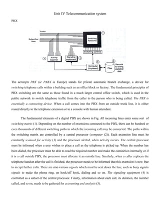
  • 1. Unit IV Telecommunication system PBX The acronym PBX (or PABX in Europe) stands for private automatic branch exchange, a device for switching telephone calls within a building such as an office block or factory. The fundamental principles of PBX switching are the same as those found in a much larger central office switch, which is used in the public network to switch telephone traffic from the caller to the person who is being called. The PBX is essentially a connecting device. When a call comes into the PBX from an outside trunk line, it is either routed directly to the telephone extension or to a console with human attendant. The fundamental elements of a digital PBX are shown in Fig. All incoming lines enter some sort of switching matrix (1). Depending on the number of extensions connected to the PBX, there can be hundred or even thousands of different switching paths to which the incoming call may be connected. The paths within the switching matrix are controlled by a central processor (computer (2)). Each extension line must be constantly scanned for activity (3) and the processor alerted, when activity occurs. The central processor must be informed when a user wishes to place a call as the telephone is picked up. When the number has been dialed, the processor must be able to read the required number and make the connection internally or if it is a call outside PBX, the processor must allocate it an outside line. Similarly, when a caller replaces the telephone handset after the call is finished, the processor needs to be informed that this extension is now free to accept further calls. There are also various signals which must be sent down the line, such as busy signals signals to make the phone ring, on hook/off hook, dialing and so on. The signaling equipment (4) is controlled as a subset of the central processor. Finally, information about each call, its duration, the number called, and so on, needs to be gathered for accounting and analysis (5).
  • 2. GSM Architecture The figure shows the three main parts that the network architecture can be divided into:  Mobile Station (MS).  Base Station Subsystem (BSS).  Net Subsystem (NS). The Mobile Station consists of the mobile equipment. Typically a mobile phone. The mobile equipment is uniquely identified by the International Mobile Equipment Identity (IMEI), which is there to prevent theft. Furthermore, the MS has to be equipped with a Subscriber Identity Module a so called SIM card. The SIM card identifies the user to the network using a International Mobile Subscriber Identity (IMSI). The SIM card can be used in different mobile equipment. The Base Station Subsystem can be divided into two parts: The Base Transceiver Station (BTS) and the Base Station Controller (BSC). The BTS houses the radio transceivers that defines a cell. The BSC manages the radio resources of one or more BTS. The Network Subsystem consists of the Mobile services Switching Center (MSC) that functions as a normal switching node of a PSTN (Public Switched Telephone Network) or an ISDN node. With the added functionality of handling Mobile stations such as: Registration, authentication, location updating, handovers, and call routing to a roaming subscriber. Furthermore, the Network Subsystem consists of four databases: The Home Location Register (HLR) that contains all the administrative information of the networks subscribers, The Visitor Location Register that contains selected administrative information from the HLR regarding the roaming users in the cells managed by the MSC, The Equipment Identity Register (EIR) and The Authentication Center provides security and authentication.
  • 3. GPRS System Architecture The GPRS is an enhancement over the GSM and adds some nodes in the network to provide the packet switched services. These network nodes are called GSNs (GPRS Support Nodes) and are responsible for the routing and delivery of the data packets to and form the MS and external packet data networks (PDN). The figure 2.2 below shows the architecture of the GPRS system. The most important network nodes added to the existing GSM networks are:  SGSN (Serving GPRS Support Node).  GGSN (Gateway GPRS Support Node). The serving GPRS support node (SGSN) is responsible for routing the packet switched data to and from the mobile stations (MS) within its area of responsibility. The main functions of SGSN are packet routing and transfer, mobile attach and detach procedure (Mobility Management (MM)), location management, assigning channels and time slots (Logical Link Management (LLM)), authentication and charging for calls. It stores the location information of the user (like the current location, current VLR) and user profile (like IMSI addresses used in packet data networks) of registered users in its location register. The gateway GPRS support node (GGSN) acts as interface between the GPRS backbone and the external packet data network (PDN). It converts the GPRS packet coming from the SGSN into proper packet data protocol (PDP) format (i.e. X.25 or IP) before sending to the outside data network. Similarly it converts the external PDP addresses to the GSM address of the destination user. It sends these packets to proper SGSN. For this purpose the GGSN stores the current SGSN address of the user and his profile in its location register. The GGSN also performs the authentication and charging functions. In general there may be a many to many relationship between the SGSN and GGSN. However a service provider may have only one GGSN and few SGSNs due to cost constraints. A GGSN proved the interface to several SGSNs to the external PDN.
  • 4. UMTS (Universal mobile telecommunication services) UMTS offers tele-services (like speech or SMS) and bearer services, which provide the ability for information transfer between access points. It is possible to negotiate and renegotiate the characteristics of a bearer service at session or connection establishment and during ongoing session or connection. Both connection oriented and connectionless services are offered for point to-Point and Point-to-Multipoint communication. Bearer services have different QoS parameters for maximum transfer delay, delay variation and bit error rate. Offered data rate targets are:  144 kbits/s satellite and rural outdoor  384 kbits/s urban outdoor  2048 kbits/s indoor and low range outdoor UMTS network services have different QoS classes for four types of traffic:  Conversational class (voice, videotelephony, video gaming)  Streaming class (multimedia, video on demand, webcast)  Interactive class (web browsing, network gaming, database access)  Background class (email, SMS, downloading) UMTS will also have a Virtual Home Environment (VHE). It is a concept for personal service environment portability across network boundaries and between terminals. Personal service environment means that users are consistently presented with the same personalized features, User Interface customization and services in whatever network or terminal, wherever the user may be located. UMTS also has improved network security and location based services. 3. UMTS Architecture
  • 5. A UMTS network consist of three interacting domains; Core Network (CN), UMTS Terrestrial Radio Access Network (UTRAN) and User Equipment (UE). The main function of the core network is to provide switching, routing and transit for user traffic. Core network also contains the databases and network management functions. The basic Core Network architecture for UMTS is based on GSM network with GPRS. All equipment has to be modified for UMTS operation and services. The UTRAN provides the air interface access method for User Equipment. Base Station is referred as Node-B and control equipment for Node-B's is called Radio Network Controller (RNC).  UMTS systems (including satellite)  Public Land Mobile Network (PLMN)  MSC/VLR or SGSN  Location Area  Routing Area (PS domain)  UTRAN Registration Area (PS domain)  Cell  Sub cell DECT Functional Concept The DECT subsystem is a microcellular or picocellular cordless telephone system that may be integrated with or connected to a Private Automatic Branch Exchange (PABX) or to the Public Switched Telephone Network (PSTN). A DECT system always consists of the following five functional entities as shown in Figure Portable Handset (PH): This is the mobile handset or the terminal. In addition, cordless terminal adapters (CTAs) may be used to provide fax or video communications. Radio Fixed Part (RFP): This supports the physical layer of the DECT common air interface. Every RFP covers one cell in the microcellular system. The radio transmission between RFP and the portable unit uses multi carrier TDM A. A full duplex operation is achieved using time division duplexing (TDD). Cordless Controller (CC or Cluster Controller): This handles the MAC, DLC, and network layers for one or a cluster of RFPs and thus forms the central control unit for the DECT equipment. Speech coding is done in the CC using 32 kbps ADPCM. Network-specific Interface Unit : This supports the call completion facility in a multihandset environment. The interface recommended by the CCITT is the G.732 based on ISDN protocols.
  • 6. Supplementary Services: This provides centralized authentication and billing when DFCT is used to provide telenoint services and mobility management when DECT is used in multilocation PAPX network. Wi-Fi (wireless fidelity) Wi-Fi is a popular wireless networking technology. Wi-Fi stands for “wireless fidelity”. The Wi-Fi was invented by NCR corporation/AT&T in Netherlands in 1991. By using this technology we can exchange the information between two or more devices. Wi-Fi has been developed for mobile computing devices, such has laptops, but it is now extensively using for mobile applications and consumer electronics like televisions, DVD players and digital cameras. There should be two possibilities in communicating with the Wi-Fi connection that may be through access point to the client connection or client to client connection. Wi-Fi is a one type of wireless technology. It is commonly called as wireless LAN (local area network). Wi-Fi allows local area networks to operate without cable and wiring. It is making popular choice for home and business networks. A computer’s wireless adaptor transfers the data into a radio signal and transfers the data into antenna for users. The following list summarizes some of the benefits of a Wi-Fi network. • Wireless Ethernet: Wi-Fi is an Ethernet replacement. Wi-Fi and Ethernet, both IEEE 802 networks, share some core elements. Extended Access: The absence of wires and cables extends access to places where wires and cables cannot go or where it is too expensive for them to go. Cost Reduction: As mentioned above, the absence of wires and cables brings down cost. This is accomplished by a combination of factors, the relatively low cost of wireless routers, no need for trenching, drilling and other methods that may be necessary to make physical connections. Mobility: Wires tie you down to one location. Going wireless means you have the freedom to change your location without losing your connection. Flexibility: Extended access, cost reductions, and mobility create opportunities for new applications as well as the possibility of creative new solutions for legacy applications. Blue tooth Bluetooth works in the Industrial, Scientific and Medical (ISM) band from 2400-2483.5 MHz (including guard bands) from mobile as well as fixed devices by creation of PANs with high security level. Several
  • 7. devices can be connected by using this technology, overcoming synchronization problems. Bluetooth uses technology called Frequency-Hopping Spread Spectrum (FHSS) which is a radio technology. The data to be transmitted is first divided into packets and then each packet is made to transmit on one among the designated 79 Bluetooth channels. Bandwidth of each channel is 1 MHz. The very first channel starts at frequency of 2402 MHz and goes up to 2480 MHz in steps of 1 MHz. Usually it performs 1600 hops per second Bluetooth is a packet-based protocol which is having a master-slave structure. In a piconet up to 7 slaves can be communicated by one master. Timing on the network can be controlled by Bluetooth by designating one device as a slave and the other as a master. The unit which initiates communication link is master and the other participants are slaves. After breakdown of link, the designations of master/slave no longer apply. Fact is that, every Bluetooth device is having both master and slave hardware. The network is called as piconet, which means a small network. When number of slaves is only one, then link is called as point-to-point. In a point-to-multipoint configuration up to seven active slaves can be controlled by a master  When a device want to connect to another device via Bleutooth it first enters an inquiry substate. This allows it to scan, or inquire, for detectable devices. Every device that is detectable enters inquiry scan substate once per given time. When the inquiry scan substate registers an inquiry from a master device it enters the inquiry response substate and answers with an inquiry response message which includes the device’s address and clock.  The master will receive such a message from all detectable devices in range. Therefore the wanted device is usually manually detected. When this is done the device enters paging substate. If  the other device is set to connect to other devices it enters page scan substate once per given time.
  • 8.  When the slave receives a page packet from the master it responds with a page response packet. Upon receiving the master shall send several synchronization packets to adjust synchronize the frequency hopping and clock in both devices. When this is done the devices go into connection state.  In transmission state the devices take on any of the four following states: active sniff, hold or park state. Active state means that both devices are connected constantly and are always listening transmitting or receiving on the channel. In sniff state the slave stops scanning for the masters packets on all channels but listens in on specific channels on specific times, saving energy. In hold mode the slave does not listen to channels connecting multiple devices in the piconet. It goes into a low power sleep mode allowing the channel to be used for paging and scanning. When in park mode the slave is not an active part of the network or piconet. Its Bluetooth address switches from active member address to passive member address FAX The essential parts of a fax system are the transmitting devices that translate the graphic material into electrical impulses according to a set pattern, and a synchronized receiving device that retranslates these impulses and prints that. In a typical system, the fax scanner consists of a rotating cylinder, a source projecting a narrow beam of light and a photoelectric cell. The copy to be transmitted is wrapped around the cylinder and is scanned by the light beam, which moves along the cylinder as it revolves. The output of the photoelectric cell is amplified and transmitted to the receiving end, where a similar cylinder, covered with specially impregnated paper, revolves in synchronism with the transmitting cylinder. A light of varying intensity moves along the rotation cylinder and darkens the paper by chemically reproducing the pattern of the original. When the fax is done, it pops out as a blue print of what the other person sent. 1. To send a fax, you feed the page into the input slot and it's pulled in between several pairs of rollers. Larger fax machines have built-in document feeders that automatically feed in multiple pages from a stack, so you don't have to stand at the machine feeding in pages one at a time. 2. As the paper moves down, a bright light shines onto it. White areas of the page reflect a lot of light; black areas reflect little or none. 3. The light reflects off the page into a light-detecting CCD (charged-coupled device)
  • 9. 4. The CCD turns the analog pattern of black and white areas on the page into a numeric (digital) pattern of binary zeros and ones and passes the information to an electronic circuit. 5. The circuit sends the digital information down the telephone line to the fax machine at the receiving end. 6. When you receive a fax, the same circuit takes incoming digital information from the phone line and routes it to a built-in printer. 7. In a typical personal fax machine, paper is pulled from a large roll inside the machine. (In a larger office fax machine, it usually comes from a plain-paper hopper, similar to the one in a laser printer.) 8. The thermal (heat-based) printer, operated by the circuit, reproduces the incoming fax on the paper as it moves past. 9. An automatic blade cuts the page and the printed fax emerges from the output slot. IMT 2000 IMT 2000 (International Mobile Telecommunications for the year 2000) is a worldwide set of requirements for a family of standards for the 3rd generation of mobile communications. The IMT-2000 "umbrella specifications" are developed by the International Telecommunicatons Union (ITU). Originally it was the intention to have only one truly global standard but that turned out to be impossible. IMT-2000 should provide worldwide mobile broadband multimedia services via a single global frequency band. The frequency range should be around 2000 MHz.
  • 10. In the umbrella specification a number of characteristics are defined which the underying technologies should meet. The main characteristics are:  Worldwide usage, integration of satellite and terrestrial systems to provide global coverage;  Used for all radio environments, (LAN, cordless, cellular, satellite);  Wide range of telecommunications services, (voice, data, multimedia, internet);  Support both packet-switched (PS) and circuit-switched (CS) data transmission;  Offer high data rates up to 2 Mbps, o 144 kbps for high mobility, o 384 kbps with restricted mobility and, o 2 Mbps in an indoor office environment;  Offer high spectrum efficiency; Wireless Local Loop Local loop is a circuit line from a subscriber’s phone to the local central office (LCO). But the implementation of local loop of wires is risky for the operators, especially in rural and remote areas due to less number of users and increased cost of installation. Hence, the solution for it is the usage of wireless local loop (WLL) which uses wireless links rather than copper wires to connect subscribers to the local central office. WLL components: 1. PSTN: It is Public Switched Telephone Network which is a circuit switched network. It is a collection of world’s interconnected circuit switched telephone networks. 2. Switch Function: Switch Function switches the PSTN among various WANUs. 3. WANU: It is short for Wireless Access Network Unit. It is present at the local exchange office. All local WASUs are connected to it. Its functions includes: Authentication, Operation & maintenance, Routing, Transceiving voice and data. It consists of following sub-components:  Transceiver: It transmits/receives data.
  • 11.  WLL Controller: It controls the wireless local loop component with WASU.  AM: It is short for Access Manager. It is responsible for authentication.  HLR: It is short for Home Location Register. It stores the details of all local WASUs. 2. WASU: It is short for Wireless Access Subscriber Units. It is present at the house of the subscriber. It connects the subscriber to WANU and the power supply for it is provided locally. Advantages of WLL:  It eliminates the first mile or last mile construction of the network connection.  Low cost due to no use of conventional copper wires.  Much more secure due to digital encryption techniques used in wireless communication.  Highly scalable as it doesn’t require the installation of more wires for scaling it. Features of WLL:  Internet connection via modem  Data service  Voice service  Fax service