
Recommended
More Related Content
What's hot
What's hot (20)
Similar to CIRCLE DIAGRAM ON 1-PHASE INDUCTION MOTOR
Similar to CIRCLE DIAGRAM ON 1-PHASE INDUCTION MOTOR (20)
More from suresh shindhe
Recently uploaded
Recently uploaded (20)
CIRCLE DIAGRAM ON 1-PHASE INDUCTION MOTOR
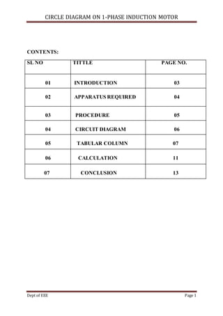
- 1. CIRCLE DIAGRAM ON 1-PHASE INDUCTION MOTOR Dept of EEE Page 1 CONTENTS: SL NO TITTLE PAGE NO. 01 INTRODUCTION 03 02 APPARATUS REQUIRED 04 03 PROCEDURE 05 04 CIRCUIT DIAGRAM 06 05 TABULAR COLUMN 07 06 CALCULATION 11 07 CONCLUSION 13
- 2. CIRCLE DIAGRAM ON 1-PHASE INDUCTION MOTOR Dept of EEE Page 2 AIM: carry out an experiment to study the performance parameters of a single phase induction motor by conducting no load and blocked rotor test ( circle diagram ). Draw the conclusion based on observation made. INTRODUCTION NO LOAD TEST In this test the motor is made to run without an load i.e no load condition. The speed of the motor is very close to the synchronous speed but less than synchronous speed. The rated voltage is applied to the stator . The input line current and total input power is measured.The two wattmeter method is used to measure the total input power in case of three phase induction motor but as in our casesingle phase induction motor input power can be measured using single wattmeter. As the motor is on no load the power factor is very low which is less than BLOCKED ROTOR TEST In block rotor test the rotor is held fixed so that it will not rotate. A reduced voltage is applied to limit the shortcircuit.This voltage is adjusted with help of autotransformer so that the rated currentflows through the main winding. The input voltage , currentand power are measured by connecting voltmeter , ammeter and wattmeter respectively. These readings are denoted as Vsc , Isc and Wsc.
- 3. CIRCLE DIAGRAM ON 1-PHASE INDUCTION MOTOR Dept of EEE Page 3 System under consideration: single phase capacitor start induction motor of rating 750 watts/1H.P ,230v ,7.8 amps ,1425 rpm . APPARATUS REQUIRED: SL.NO APPARATUS/INSTRUMENTS/NOS RANGE/TYPE 1 1-phase dimestat 230v/10A 2 Voltmeter 0-150V (MI) 0-300V (MI) 3 Ammeter 0-10A (MI) 0-5A (MI) 4 Wattmeter (1 nos) (1 nos) 300V/5A LPF 150V/10A UPF
- 4. CIRCLE DIAGRAM ON 1-PHASE INDUCTION MOTOR Dept of EEE Page 4 CIRCUIT DIAGRAM FOR NO LOAD TEST: PROCEDURE:- NO LOAD TEST 1. Make connection as per circuit diagram as shown in Fig 1. 2. Switch on the supply and vary the dimmestat till a rated voltage (230V ) is applied. 3. Take all the meter reading and switch off the supply.
- 5. CIRCLE DIAGRAM ON 1-PHASE INDUCTION MOTOR Dept of EEE Page 5 CIRCUIT DIAGRAM FOR BLOCKED ROTOR TEST: PROCEDURE:-BLOCKED ROTOR TEST 1. Make connection as per circuit diagram as shown in Fig 2. 2. Hold the rotorshaft firmly i.e block the rotor. 3. Switch on the supply and vary the dimmestat till a rated current (7.8A) flows. 4. Take all the meter reading and switch off the supply.
- 6. CIRCLE DIAGRAM ON 1-PHASE INDUCTION MOTOR Dept of EEE Page 6 CIRCUIT DIAGRAM FOR LOAD TEST: PROCEDURE:- LOAD TEST 1. Make connection as per circuit diagram as shown in Fig 3. 2. Switch on supply and vary the dimmestat till rated voltage (230V) is applied. 3. Apply the brake load in step and note down the reading of voltmeter , ammeter , wattmeter , speed and tangential forces (S1 and S2) etc. 4. Switch off the supply.
- 7. CIRCLE DIAGRAM ON 1-PHASE INDUCTION MOTOR Dept of EEE Page 7 TABULAR COLUMN NO LOAD TEST Voltmeter (V0) volts Ammeter (I0) amps Wattmeter (W0) watts 230 5.8 74 Wattmeter constant is 4. BLOCKED ROTOR TEST Voltmeter (Vsc) volts Ammeter (Isc) amps Wattmeter (Wsc) watts 59 7.8 150 Wattmeter constant is 2.
- 8. CIRCLE DIAGRAM ON 1-PHASE INDUCTION MOTOR Dept of EEE Page 8 LOAD TEST Radius of brake drum (r) =0.07m SL.NO Voltmeter (V) volts Ammeter (I) amps Wattmeter (W) watts Speed (N)rpm Load (kg) (S1) (S2) 1 212 4.5 45 1493 0 0 2 212 5.3 150 1464 6 1.5 3 212 7 210 1430 8 2 4 212 7.9 310 1412 12 6 Wattmeter constant is 4.
- 9. CIRCLE DIAGRAM ON 1-PHASE INDUCTION MOTOR Dept of EEE Page 9 CALCULATION:- (No Load and Block RotorTest) The circle diagram is drawn by following the below given procedure. Step1:calculate the No load power factor angle by equation. 𝜃𝑜 = cos−1 [ 𝑊𝑜 𝑉𝑜 × 𝐼𝑜 ] 𝜃𝑜 = cos−1 [ 296 230× 5.8 ] = 77.17° And draw a no load current line OA (Choosecurrent scale) at angle𝜃𝑜 measured from vertical axis. Step2: Calculate the short circuit power factor angle by equation. 𝜃𝑠𝑐 = cos−1 [ 𝑊𝑠𝑐 𝑉𝑠𝑐 × 𝐼𝑠𝑐 ] 𝜃𝑠𝑐 = cos−1 [ 300 59 × 7.8 ] = 49.31° Calculate normal short circuit current by equation 𝐼𝑠𝑐𝑛 = ( 𝑉𝑁 𝑉𝑠𝑐 ) × 𝐼𝑠𝑐 𝐼𝑠𝑐 = ( 230 59 ) × 7.8 = 30.40𝐴 Where, VN = 230V And draw a normal short circuit line OB at an angle 𝜃𝑠𝑐 measured from the vertical axis. Step3: Join A and B called as output line and divide the line and locate point C. Step4: With C as center point and AC as radius draw a semicircle (point B also lies on the semicircle). Step5: Draw a vertical line from point B and locate the point D and E.
- 10. CIRCLE DIAGRAM ON 1-PHASE INDUCTION MOTOR Dept of EEE Page 10 Step6: Divide the line BD (assuming equal rotor and stator copperloss)and locate the point F. Then join AF (Torque line). 𝐴𝐹 = 2 × 9.8 = 19.6 Step7: Calculate the power scale as below, Measure BE BE=10.2 cm Calculate Normal short circuit loss Pscn= (𝑉𝑁/𝑉𝑠𝑐)2 × (Wsc) 𝑃𝑠𝑐𝑛 = ( 230 59 )2 × (300) = 4559.03𝑤𝑎𝑡𝑡 Then power scale 𝑥 = 𝑃𝑠𝑐𝑛 𝐵𝐸 (w/cm) 𝑥 = 4559.03 10.2 = 446.96( 𝑤 𝑐𝑚 ) Step8: Draw output power line GB of length calculated as, 𝐺𝐵 = 𝐹𝑢𝑙𝑙 𝑙𝑜𝑎𝑑 𝑜𝑢𝑡𝑝𝑢𝑡 𝑝𝑜𝑤𝑒𝑟 (𝑤𝑎𝑡𝑡𝑠)/𝑥 𝐺𝐵 = 746 446.96 = 1.7 𝑐𝑚 Where full load output power (Pm) = 746 watts Step9: Draw a line HG parallel to AB (output line), intersecting the semicircle at point H. Step10: Draw vertical line from point H, intersecting the output line,torque line,horizontal line from A and x axis at point I,J,K,and L respectively. Also draw a line OH. Step11: Performance parameters at full load are calculated as below, 𝑖𝑛𝑝𝑢𝑡 𝑝𝑜𝑤𝑒𝑟 𝑃𝑖 = 𝐻𝐿 × 𝑥 𝐼𝑛𝑝𝑢𝑡 𝑝𝑜𝑤𝑒𝑟 𝑃𝑖 = 3 × 446.96 = 1340.88 𝑤𝑎𝑡𝑡
- 11. CIRCLE DIAGRAM ON 1-PHASE INDUCTION MOTOR Dept of EEE Page 11 𝑃𝑚 = 𝐻𝐼 × 𝑥 = 2.1 × 446.96 = 938.61 𝑤𝑎𝑡𝑡 𝑒𝑓𝑓𝑖𝑐𝑖𝑒𝑛𝑐𝑦 ƞ = 𝑃𝑚 𝑃𝑖 × 100 Ƞ = ( 938.61 1340.88 )× 100 = 70.04% 𝐴𝑖𝑟 𝑔𝑎𝑝 𝑝𝑜𝑤𝑒𝑟 𝑃𝑔 = 𝐻𝐽 × 𝑥 𝑃𝑔 = 2.3 × 446.96 = 1028.008 𝑤𝑎𝑡𝑡 𝑅𝑜𝑡𝑜𝑟 𝑐𝑜𝑝𝑝𝑒𝑟 𝑙𝑜𝑠𝑠 𝑃𝑐𝑟 = 𝐼𝐽 × 𝑥 𝑃𝑐𝑟 = 0.2 × 446.96 = 89.392 𝑤𝑎𝑡𝑡 𝑆𝑙𝑖𝑝 𝑠 = 𝑃𝑐𝑟 𝑃𝑔 𝑆 = 89.392 1028.008 × 100 = 8.69% 𝑆𝑡𝑎𝑡𝑜𝑟 𝑐𝑜𝑝𝑝𝑒𝑟 𝑙𝑜𝑠𝑠 𝑃𝑐𝑠 = 𝐽𝐾 × 𝑥 𝑃𝑐𝑠 = 0.2 × 446.96 = 89.392 𝑤𝑎𝑡𝑡 𝑅𝑜𝑡𝑎𝑡𝑖𝑜𝑛𝑎𝑙 𝑙𝑜𝑠𝑠 = 𝐾𝐿 × 𝑥 𝑅𝑜𝑡𝑎𝑡𝑖𝑜𝑛𝑎𝑙 𝑙𝑜𝑠𝑠 = 0.6× 446.96 = 268.17 𝑤𝑎𝑡𝑡 𝑆𝑡𝑎𝑡𝑜𝑟 𝑐𝑢𝑟𝑟𝑒𝑛𝑡 𝐼 = 𝑂𝐻 × 𝑐𝑢𝑟𝑟𝑒𝑛𝑡 𝑠𝑐𝑎𝑙𝑒 𝐼 = 4.5 × 2 = 9𝐴 Input power factor pf = cos (angle between vertical axis and line OH) 𝑝𝑓 = cos(47°) = 0.681
- 12. CIRCLE DIAGRAM ON 1-PHASE INDUCTION MOTOR Dept of EEE Page 12 CIRCLE DIAGRAM: CALCULATION:- ( Load Test) 𝐼𝑛𝑝𝑢𝑡 𝑝𝑜𝑤𝑒𝑟 𝑃𝑖 = 𝑊 735.5 𝑃𝑖 = 1240 735.5 = 1.685𝑤𝑎𝑡𝑡 𝑇𝑜𝑟𝑞𝑢𝑒 𝑇 = 9.81× ( 𝑆1 − 𝑆2) × 𝑟
- 13. CIRCLE DIAGRAM ON 1-PHASE INDUCTION MOTOR Dept of EEE Page 13 𝑇 = 9.81× (12− 6) × 0.07 = 4.120 𝑁𝑚 𝑂𝑢𝑡𝑝𝑢𝑡 𝑝𝑜𝑤𝑒𝑟 𝑃𝑜 = 2𝜋𝑁𝑇 60× 735.5 𝑃𝑜 = 36542.05 44130 = 0.828𝑤𝑎𝑡𝑡 %𝐸𝑓𝑓𝑖𝑐𝑖𝑒𝑛𝑐𝑦( ƞ ) = ( 𝑃𝑜 𝑃𝑖 ) × 100 ƞ = ( 0.828 1.685 ) × 100 = 49.13% 𝑃𝑜𝑤𝑒𝑟 𝑓𝑎𝑐𝑡𝑜𝑟 𝑝𝑓 = 𝑊 𝑉𝐼 𝑝𝑓 = 1240 1674.8 = 0.74 𝑆 = 𝑁𝑠 − 𝑁 𝑁𝑠 × 100 = 1500 − 1429 1500 × 100 = 4.73% CALCLULATION TABLE Test Torque (Nm) Input power(W) Out put power(W) Efficiency Slip Circle diagram 19.6 1340.88 938.61 70.04% 8.69% Load test 4.12 1.685 0.828 49.13% 4.73%
- 14. CIRCLE DIAGRAM ON 1-PHASE INDUCTION MOTOR Dept of EEE Page 14 CONCLUSION o We obtained the efficiency (ƞ) of single phase induction motor from circle diagram is 70.04% where as, from full load test it is 49% hence from circle diagram method, we cannot obtain accurate efficiency for single induction motor. o Because normally torque for single phase induction motor is less for load test, where as we obtained from circle diagram is very high hence the efficiency is high in case of circle diagram compare to load test. As torque is directly proportional to output power. o So generally circle diagram is not drawn for single phase induction motor to find efficiency.