Dynamics of Machines - Unit II-Balancing of Rotating Masses
•
3 likes•312 views

Dynamics of Machines Unit II-Balancing of Rotating Masses *Short notes *MCQ

Recommended
More Related Content
What's hot
What's hot (20)
Similar to Dynamics of Machines - Unit II-Balancing of Rotating Masses
Similar to Dynamics of Machines - Unit II-Balancing of Rotating Masses (20)
More from Dr.S.SURESH
More from Dr.S.SURESH (15)
Recently uploaded
Recently uploaded (20)
Dynamics of Machines - Unit II-Balancing of Rotating Masses
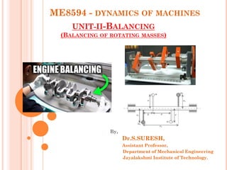
- 1. ME8594 - DYNAMICS OF MACHINES UNIT-II-BALANCING (BALANCING OF ROTATING MASSES) By, Dr.S.SURESH, Assistant Professor, Department of Mechanical Engineering Jayalakshmi Institute of Technology.
- 2. WHAT IS MEANT BY BALANCING Balancing is the process of designing or modifying machinery so that the unbalance is reduced to an acceptable level and if possible is eliminated entirely.
- 3. Different types of balancing 1. Balancing of rotating masses I. Static balancing II. Dynamic balancing 2. Balancing of reciprocating masses.
- 4. BALANCING OF ROTATING MASSES Certain mass (m1) is attached to a rotating shaft It exerts some centrifugal force Bend the shaft and to produce vibrations In order to prevent the effect of centrifugal force Another mass (m2) is attached to the opposite side of the shaft centrifugal force of both the masses are made to be equal and opposite. rotating masses are balanced
- 5. The following cases are important from the subject point of view: 1. Balancing of a single rotating mass by a single mass rotating in the same plane. 2. Balancing of a single rotating mass by two masses rotating in different planes. BALANCING OF ROTATING MASSES
- 6. 3. Balancing of different masses rotating in the same plane. 4. Balancing of different masses rotating in different planes.
- 7. Let r1 = radius of rotation of the mass m1 m1 = a disturbing mass attached to a shaft rotating at ω rad/s. Centrifugal force exerted by the mass m1 = 1) Balancing of a single rotating mass by a single mass rotating in the same plane. m2 = balancing mass For complete balance = FC1 = FC2 CASE 1
- 8. 3. BALANCING OF SEVERAL MASSES ROTATING IN THE SAME PLANE m1, m2, m3 and m4 = Magnitude of masses (Kg) r1, r2, r3 and r4 = Radius of rotation (m) θ1, θ2, θ3 and θ4 = angles of these masses with the horizontal line OX ω = Constant angular velocity (rad/s). CASE 3
- 9. The magnitude and position of the balancing mass may be found out analytically or graphically. 1. Analytical method (i) Find out the centrifugal force Fc = m . R (ii) Resolve the centrifugal forces horizontally and vertically and find their sums, i.e. ∑ H and ∑V ∑ H = m1 r1 cos θ1 + m2 r2 cos θ2 + m3 r3 cos θ3 ∑V = m1 r1 sin θ1 + m2 r2 sin θ2 + m3 r3 sin θ3 (iii) Magnitude of the resultant centrifugal force
- 10. (iv) If θ is the angle, which the resultant force make with the horizontal tan θ = ∑V / ∑H (v) The balancing force is then equal to the resultant force, but in opposite direction. (vi) Now find out the magnitude of the balancing mass, such that
- 11. Example: 1. Four masses m1, m2, m3 and m4 are 200 kg, 300 kg, 240 kg and 260 kg respectively. The corresponding radii of rotation are 0.2 m, 0.15 m, 0.25 m and 0.3 m respectively and the angles between successive masses are 45°, 75° and 135°. Find the position and magnitude of the balance mass required, if its radius of rotation is 0.2 m. Given Data: m1= 200 kg ; m2= 300 kg ; m3= 240 kg ; m4= 260 kg ; r1= 0.2 m ;r2= 0.15 m ; r3= 0.25 m ; r4= 0.3 m ; θ1 = 0° ; θ2 = 45° ; θ3 = 45° + 75° = 120° ; θ4 = 45° + 75°+ 135° = 255° ; r = 0.2 m To find: Magnitude and position of the balance mass (m & θ)
- 12. SOLUTION: Magnitude of centrifugal forces 1. Analytical method Resolving m1.r1, m2.r2, m3.r3 and m4.r4 horizontally, Resolving m1.r1, m2.r2, m3.r3 and m4.r4 vertically, = m1 r1 cos θ1 + m2 r2 cos θ2 + m3 r3 cos θ3 = m1 r1 sin θ1 + m2 r2 sin θ2 + m3 r3 sin θ3
- 13. Resultant centrifugal force = We know that ... R = m.r = 23.2 Direction of Resultant force Angle of the balancing mass from the horizontal mass of 200 kg m = 116 kg Ans. θ = 201.48° Ans.
- 15. Graphical Method 1. Draw the space diagram showing the positions of all the given masses as shown in Fig. Space diagram 2. Centrifugal force of each mass
- 16. 3. Draw the vector diagram with the above values, to some suitable scale Vector Diagram Space Diagram Scale: 1 cm: 10 kg.m Measurement from Vector diagram Find that Balancing force is equal to resultant force but opposite in direction ae = Resultant Force = 23 kg-m
- 17. 4. BALANCING OF DIFFERENT MASSES ROTATING IN DIFFERENT PLANES In order to have a complete balance of the several revolving masses in different planes, the following two conditions must be satisfied : 1. The forces in the reference plane must balance, i.e. the resultant force must be zero. 2. The couples about the reference plane must balance, i.e. the resultant couple must be zero. CASE 4
- 18. m 1, m 2, m 3 & m 4 = Revolving in planes 1, 2, 3 and 4 m L & m M = Balancing masses in the plane M and N Rp = Reference Plane Position of planes of the masses Angular position of the masses CASE 4. BALANCING OF DIFFERENT MASSES ROTATING IN DIFFERENT PLANES
- 19. EXAMPLE 1 A shaft carries four masses A, B, C and D of magnitude 200 kg, 300 kg, 400 kg and 200 kg respectively and revolving at radii 80 mm, 70 mm, 60 mm and 80 mm in planes measured from A at 300 mm, 400 mm and 700 mm. The angles between the cranks measured anticlockwise are A to B 45°, B to C 70° and C to D 120°. The balancing masses are to be placed in planes X and Y. The distance between the planes A and X is 100 mm, between X and Y is 400 mm and between Y and D is 200 mm. If the balancing masses revolve at a radius of 100 mm, find their magnitudes and angular positions. CASE 4- Balancing of different masses rotating in different planes Given data: To find m A = 200 kg , rA = 80 mm (i) Magnitude of Balancing masses (mX, mY) m B = 300 kg, rB = 70 mm (ii) Angular positions of Balancing masses m C = 400 kg, rC = 60 mm (θX , θY) m D = 200 kg, rD = 80 mm
- 20. Solution: Plane Mass (m) (Kg) Radius (r) (m) Cent. Force (Fc=m.r) (kg.m) Distance from RP (l) (m) Couple (m.r.l) (Kg.m2) A X (RP) B C Y D 200 m X 300 400 m Y 200 0.08 0.1 0.07 0.06 0.1 0.08 16 0.1 m X 21 24 0.1 m Y 16 -0.1 0 0.2 0.3 0.4 0.6 -1.6 0 4.2 7.2 0.04 m Y 9.6
- 21. • Couple Polygon Scale: 1 cm = 1 kg.m 2 By measurement from couple polygon 0.04 m Y = Vector d | o | = 7.3 Kg-m 2 Angular position of mY
- 22. Force Polygon Scale: 1 cm = 5 kg.m By measurement from force polygon Angular position of mX