1. Experimental Stress Analysis
Prof. K. Ramesh
Department of Applied Mechanics
Indian Institute of Technology, Madras
Module No # 01
Lecture No # 10
Selection of an Experimental Technique
(Refer Slide Time: 00:18)
2. (Refer Slide Time: 00:44)
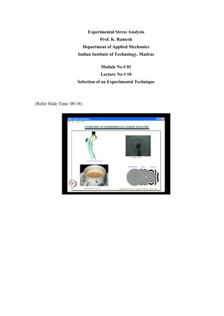
We come to the concluding part of our discussion on overview of experimental stress
analysis. This slide was shown at the beginning of this chapter and now you must be
familiar in identifying various techniques that are depicted in this slide. Here you see the
usage of photo elasticity for finding out the stress patterns and you find the use of
techniques like moiré holography or shearography to reveal various fringe patterns. You
find this as the out of plane displacements. Now you know that this is the slope, this is
the curvature information and each of this requires separate optical arrangements. You
may get this displacement by the technique of holography or speckle interferometry or
shadow moire. What you see is the simulated fringe patterns and when you really make
an experiment the fringe patterns will follow this closely but the quality of the fringes
depends on the technique that is being used.
The moment you come here you see this as butterfly fringes which you get from
shearography. You can also get it from a variation of moire and this curvature fringes
from shearing interferometry. So now you have a familiarity how the whole field
information looks like.
3. (Refer Slide Time: 00:18)
So this knowledge will go a long way in appreciating what patterns you have and how
you have to interpret them when doing the experiments. These two corner slides bring
out the physics for each of the techniques. You see this as a method of caustics which is
also seen in the case of moire. You also have beautiful moire patterns coming out and the
term moire has an origin from fringe.
(Refer Slide Time: 03:13)
We have been discussing on selection of an appropriate experimental technique and we
will go back and review what we have seen till now. One of the crucial steps in
4. experimental analysis is to identify a suitable technique for a given problem. We have
seen that it depends on several factors like time available for analysis, level of accuracy
required, range of strain or stress to be measured, influence of extreme conditions like
high temperature, high strain rate etc. You also have to look at what thorough study is
required and finally the cost permissible for the study.
(Refer Slide Time: 03:59)
Then what we looked at was if the location of the point of interest in a component is
known and if it is few in number then strain gauge technique is a right choice as it can be
applied to various situations. One of the greatest advantages of strain gauge is that it is
ideal for in situ measurements over long period of time as it is necessary for monitoring
structural health which you need to do that for bridges and dams. This comes as an ideal
technique for remote locations, rotating components and also applicable from elastic to
plastic range and also dynamic or transient phenomena
5. (Refer Slide Time: 05:19)
So what we find here is that it is more of a general purpose technique which is
advantageous when you go in for strain. We have also looked at in detail about certain
issues in using photo elasticity. Suppose I want whole field appreciation of the stress
field, then photo elasticity is the right choice. We have seen for a stress concentration
problem plate with a hole, plate with an elliptical hole for crack problem and spanner
with different designs.
So when I want to know what happens on the entire field, photo elasticity would do it
quickly and this can be applied to a range of problems from static to dynamic analysis.
You have many variants of photo elasticity which can be selected for measuring residual
stresses, assembly stresses and most importantly stresses interior to the body.
Similarly when I want to go and look at what is interior to the body the problems are
always complex and photo elasticity provides the revenue. Recently you have seen in the
paper that Honda has asked certain components to be called back in the recent cost that
they have fabricated and released in the market. So when you are really looking at the
design you have such flaws and people have to call back and then replace the
component. In such applications a detailed analysis involving both numerical and
experimental analysis is a must. If you go back in history, in many engineering
applications people have done in detail three dimensional analysis using photo elasticity.
So this is one of the strong points as far as photo elasticity is concerned and what you
6. have is that an intelligent use of photo elasticity with strain gauge can solve a variety of
problems that commonly occur in normal design scenarios and also in special situation.
In fact you have concorde aircraft though it is grounded after the accident in France, was
one of the aircraft which had very least amount of failures in the field. There were no
accidents till it was grounded. It had a tail rudder which was failing repeatedly.
You know in those days about in seventies, finite element analysis was done to find out
the cost for the rudder failure. From finite element point of view, the rudder is found to
be reasonably strong to withstand the service loads which never failed. So what they did
they took a strain gauge and put it on the rudder and made measurements. When they
compared their strain gauge values with design calculations it showed that it is within the
permissible limits. Something what they could not identify from a numerical technique
or a point by point experimental technique was the cost as the component was failing in
the field. So they had to go for a whole field experimental measurement. They applied a
photo elastic coating and found that the maximum stress point was slightly shifted and
the strain gauge was reading only two third of its maximum value. The moment they
applied photo elastic coating, they identified the point of stress concentration and put the
strain gauges which made the design perfect and the problem was solved. So what you
need to do is in many practical problems, identifying what to do which is the critical area
itself is a challenge.
(Refer Slide Time: 09:58)
7. So a combination of whole field and a point by point technique help you to solve day to
day design problem. In special situations you can always fall back on either photo
elasticity or strain gauges. You need special techniques to address special problem
situations and the moment you think of moire interferometry you have to think of
electronic packaging industry which has found wide acceptance.
In electronic packaging industry, to measure thermally induced stresses on tiny
components moire is ideally suitable as the components are very small where I cannot go
and paste the strain gauge. Moire gives the whole field information and researches
convincingly show that moire is applicable for these classes of problems. For MEMS
application speckle and holographic methods are ideally found to be suitable. In an
MEMS censor we have seen how a speckle method could be employed and how they
have used holographic method to study a micro gear rotating at 360000 rpm. So in
MEMS application if you have the need think of either speckle or holographic methods.
Then you have the method of thermo elastic stress analysis which is useful to measure
stresses developed due to fatigue or random loadings. It is a very special application
people have applied using thermo elastic stress analysis. The methodology seems to be
promising for unconventional applications such as stresses introduced in slamming of
automobile doors. In fact you know in automobile industry people are very particular
about the shape, so they keep changing the shape of the automobile. They all have
streamline contours that travel at very high speeds and there is a pressure on them to
bring out new variance. All this is a sheet metal work and you need to find out for the
given life whether the doors will withstand. So slamming of the door is a random loading
as it is a three dimensional problem. You can apply thermo elastic stress analysis to it as
you have a contoured shape where you need to slam it and make the measurement.
So as technology advances you get newer problems. In fact if you compare, in seventies
and eighties the cars did not have smooth contour they had box type. Now what you have
is streamline contours, new manufacturing technologies and more and more increase in
speed. All these bring in new class of problems which also require newer techniques to
solve.
8. (Refer Slide Time: 13:56)
The moment you think of vibration, holography is an ideal choice. If you want to find
out the mode shape you would normally sprinkle sand or lycopodium powder on a flat
object. As long as I am working with the flat plate of different shapes I can do the
analysis with sand or lycopodium powder. If I want to do it for a turbine blade which has
a twisted complex aero foil shape then holography cab ne used because it is essentially
out of plane measurement technique. More composite and honeycomb panels are used in
space technology. So they all have the delamination problem.
Speckle methods in its variation as shearography is very useful as an NDT tool in
aerospace industries. As I have been saying photo elasticity and strain gauges are
general purpose tools, similarly methodology of digital image correlation is also
attractive as a general purpose tool. This technique is still developing and its accuracy
level needs to be improved further for low strain measurements. Sometime back the low
strain was about 160 micro strain and now people say that you can go up to 50 micro
strain. So as the technology is improving you are also improving the capability of the
technique to measure smaller values of strain.
9. (Refer Slide Time: 16:41)
What you have to keep in mind is that whatever the guidelines we have discuss so for are
not complete and the experimentalist is acumen in deciding an appropriate technique and
an intelligent use of an existing technique in unconventional situations is always
welcome. You should never forget that your engineering acumen is required to
intelligently attack complex problems with simpler combination of existing methods.
Doctors have the acumen in detecting what is the disease you people have and he is only
able to identify the disease correctly and solve your problem.
So similarly engineers also have to understand what is the requirement of the given
design scenario, select an appropriate technique and solve the problem. Another issue is
what level of accuracy you can expect in experiments and you have to understand that
there is no upper limit for accuracy. You can keep improving the accuracy in an
experimental technique, you may start with a simpler rate and make some measurements
and once you understand the scenario you may want to improve it as much as possible.
So as one improves the experimental set up, the accuracy can be improved and there is
no upper limit for accuracy. The deciding factors to improve the accuracy are the cost
and the time available for analysis. So if some designer wants a quick answer you could
give a number with certain level of accuracy and can always use a factor of safety to
carry on with the design and have a very precise analysis. See normally when people
want to make a helicopter to fly they will make it fly first, optimization will come later
10. where you need refined analysis. When you are talking about accuracy I would like to
caution that when you compare your experimental results with analytical solution, for
example, if I want to find out the free end displacement of a cantilever so you have p l q
by 3 e i. What you will do is you will find out what is the displacement from your
experiment. For the moment you consider that there is no shear deformation, the depth is
very small but even then when I make my analytical calculations I need to feed in the
value of moment of inertia and moment of inertia is b d q by 12. If you do not measure
the depth of the beam correctly, then what will happen? You will make an error on
analytical calculation of the displacement because I have b d q by 12 it will have a very
high error and p l q by 3 e i will not match with experiment. So you should not always
blame the experimental technique when analytical and experimental techniques do not
match.
In your analytical calculation have you provided correct numbers for calculation is also
very important. See if I give a ten specimen to a student he uses a scale and measure the
thickness. You have to use a vernier and measure the thickness. When thickness and
small distance is to be measured, you should use the precision and this many people
ignore when they compare analytical method results to experiment. Even for analytical
calculation you need to feed in some measurement by making actual measurements on
the component of object. So these measurements need to be precise. You should use
methods of principles of statistics, take few measurements, and take an average of all
that you should employ. People never use statistics they go and measure once and then
say that this is the value. You will also always have an averaging procedure which is also
equally important.
So when we say experiments there is no upper limit. For accuracy, you should also
cautious when you are doing an analytical calculation; those calculations have to be
accurate enough. What we will look at now is based on the stress strain history. We will
look at a broad classification of suitability of different techniques for different ranges of
strain in the next slide.
11. (Refer Slide Time: 22:31)
I have taken a typical stress strain graph to show that I have a very small elastic region
and a very large plastic region. What we will look at is the range we can use for the
curve in brittle coating, photo elasticity, strain gauge and thermo elastic stress analysis as
visual representation always helps in identifying in what region I am working elastic or
plastic. In brittle coating we all see that the failure strain of the coating decides the lower
limit and we saw that it is about 300 to 500 micro strain. As newer materials are
developing, you may be able to bring it down but the threshold limit is about 300 to 500,
so you will have brittle coating in this zone.
So when you are operating in this colored zone as shown in the Refer Slide Time: 22:31,
the stress strain is about 300 micro strain and when it has the elastic point, it is about
2000 micro strain. So in brittle coating which is used to identify plastic deformation, we
cannot go to lower strain levels. This is the typical range where brittle coating can be
employed.
12. (Refer Slide Time: 24:41)
(Refer Slide Time: 25:06)
What you need to worry about is the end point and the start point. So in photo elasticity,
photo elastic analysis will confine only in the elastic region. The moment you come to
strain gauge we have seen currently you have techniques which can measure even 0.5
micro strain which is almost close to zero. You can also go to the plastic region about 10
to 12 percent of strain which can be easily measure with strain gauges. That is the reason
we say that strain gauge is a versatile technique.
13. (Refer Slide Time: 25:45)
(Refer Slide Time: 26:19)
So it has a longer range where I can go from elastic to plastic comfortably and thermo
elastic stress analysis is proposed as a whole field strain gauge technique. The strain
gauge instrumentation is simpler when compared to TSA, but both the instrumentations
are expensive. Now you have relative zones for different techniques as shown in Refer
Slide Time: 26:29 which will help to find out which way you will select the existing
technique.
14. (Refer Slide Time: 26:51)
Here we will have similar graph for other four techniques which are grid methods used
for very high plastic region, geometric moire, moire interferometry which is the
refinement of geometric moire and digital image correlation which has large range but
does not have accuracy at lower strain levels.
So when you look at grid methods it is applied only in the highly plastic region. The
range is shown in Refer Slide Time: 26:51.
(Refer Slide Time: 27:46)
15. When you come to geometric moire, it would be here as shown in Refer Slide Time:
27:47 and if you want to lower it then you can go for moire interferometry. What you
need to worry about is the end point and start point and the issue here is the range of
strain that you are really looking at.
(Refer Slide Time: 28:24)
Moire interferometry cannot measure very small strains it can go down but it cannot go
close to zero as shown in Refer Slide Time: 28:24.
(Refer Slide Time: 28:48).
16. And when I come to digital image correlation I can go from one end to another as shown
in Refer Slide Time: 28:48. It can be brought down to as close as zero by improving the
technology on which the researchers are working. Their claim is now about 50 micro
strain and it is only a question of time that they improve the technique further.
(Refer Slide Time: 29:23)
Now you have relative appreciation of various techniques as shown in Refer Slide Time:
29:23to decide the techniques based on the strain range.
(Refer Slide Time: 29:54)
17. And now we come to the important step of looking at what are all the references that you
need to have a look at. You have a recently published third edition of springer handbook
of experimental solid mechanics which has a large number of techniques compiled in one
volume and it is edited by W N Sharpe. In this handbook, we have a chapter on photo
elasticity which covers the modern development of photo elasticity and it also give a
nutshell variant of photo elasticity.
Then you have a very famous book optical methods of engineering analysis by Gary
Cloud published in 1998 who has given a series of articles in experimental techniques.
He is writing articles on various optical methods for displacement stress and strain
measurement which are very interesting.
The next you have is a book on digital photo elasticity written by me. This completely
covers the development of photo elasticity from conventional techniques to digital photo
elasticity and exhaustively gives you various methodologies including phase shifting
techniques, Fourier transform techniques, color image processing methods and also
application to fracture mechanics and stress separation.
Then you have handbook of moire fringe technique published in 1993 and high
sensitivity moire published in 1994. Here the focus is more on applying this moire
technique for thermal stress analysis problem. There is also a separate chapter that was
written in the book on experimental analysis for mechanics and materials.
(Refer Slide Time: 33:21)
18. Next you have two references on holography. I have a book on holographic
interferometry by Rastogi published in 1994 and the engineering applications of lasers
and holography by Kock published in 1979. For each of the techniques and sub
techniques you have separate books available. We have another book on holographic
interferometry written by C M Vest.
Then you have a book on speckle methodology a group of interferometric techniques by
R S Sirohi. He had a very good lab at IIT Madras and several of his students have made
significant contributions in the area of speckle methodology.
And finally you have a book by Asundi who has done more computer processing had
come out with how MATLAB can be used for photo mechanics. We have already seen
when we looked at trends in experimental mechanics that the current trend is on finding
out phase shifting techniques which are used in several interferometric methods. All
these interferometric methods use CCT camera as an electronic eye and the image
processing is done. For many of the image processing application MATLAB could be
advantageously used. That is why Asundi has come up with the book on MATLAB for
photo mechanics.
(Refer Slide Time: 36:58)
Then what we will look at is review of solid mechanics. The important aspect here is, in
a 2 dimensional problem without resorting to the Mohr circle approach how would you
find the principle stress and their corresponding directions uniquely. If you look at, in
19. your learning your focus was mainly on failure analysis and finding out truss kyle yield
criteria or one mises yield criteria where you need only magnitudes of principle stresses.
As we are not bothered about the direction theta we will not look at what are the (( )) in
finding out the direction. In fact if somebody says if you have an expression for theta
whether it represents maximum principle stress direction or minimum principle stress
direction you cannot say with the simple calculation of trigonometric equation.
(Refer Slide Time: 38:25)
Let us look at that equation which is given as theta equal to tan inverse 2 tau xy divided
by sigma x minus sigma y multiply by half. As this expression is a trigonometric
expression it will give you multiple values of theta. How will you associate it is in Mohr
circle if you know how Mohr circle is drawn and interpreted then you will be able to fix
up the theta which corresponds to sigma 1 direction. This theta what I have calculated
plus 90 degrees will give me sigma 2 direction. When I use this standard analytical
expression this expression cannot give it.
So you need to do something extra. When I do an experimental technique to find out the
sigma 1 direction and sigma 2 direction, I use auxiliary methods to convincingly find out
whether it is direction for sigma 1 or sigma 2. This was a problem in digital photo
elasticity. So here you need to pose the problem differently and do it as an Eigen value
Eigen vector approach. Here I get principle stresses as Eigen values and the direction
20. cosine n x and n y as the corresponding direction. So I have the Eigen value and Eigen
vector.
(Refer Slide Time: 41:09)
When I repose the problem as Eigen value and Eigen vector it is possible for me to find
out value of sigma 1 and corresponding theta. The greatest one is sigma 1 the smallest
one is sigma 2 and sigma 3. Now the question is that how you will associate theta to
sigma 1 direction and sigma 2 direction as you get 2 values of theta. You can do if you
reformulate the problem as an Eigen value and Eigen vector approach. So when you do
that it is possible for you to find out n x and n y from simple arithmetic.
21. (Refer Slide Time: 36:58)
So analytically also we need to do special efforts to find out this. When I do by
experiment particular by photo elasticity, you will see that I have to use some kind of a
calibration to associate the direction obtained to sigma 1 or sigma 2 and the emphasis
here is more on finding out the principles of direction.
Next we have is finding out the stress tensor in a transformed coordinate systems. In fact
in the whole of strain gauge analysis if you know the tensor transformation law you can
comfortably understand that stress and strain are a tensor of rank 2. So once you know
the transformation law whole of strain gauges can be handled.
Then we have what is the mathematical definition of a free surface when the stress tensor
on free outward corners is specified. Now let us get in to the details of this.
22. (Refer Slide Time: 43:16)
So what I have here is a mathematical definition of a free surface and we have to find out
the stress vector. In solid mechanics we have learnt state of stress at a point gives you
totality of all the stress vectors on all the possible infinite planes passing through the
point of interest. A surface is defined by an outward normal and if n is the outward
normal of a surface then the stress vector on that plane is obtained by multiplying stress
tensor with the direction cosines.
So what you have here is T n equal to tau into n where n is the direction cosine vector,
tau is the stress tensor at the point of interest and T n is the stress vector acting on plane
which is defined by outward normal. On a free surface, stress tensor need not be zero but
stress vector is necessarily zero. So the mathematical definition of free surface is T n
equal to zero.
We will see this by an example. So if I have to find out the stress vector on any specified
I can go to Koshish formula and make a statement that on a free surface, stress vector is
necessarily zero. The corollary of this is that at the stress vector direction on a free
surface can at best be tangential to the surface. In other words stress vector cannot cross
the free boundary which is what I get from looking at Koshish formula and the
mathematical expression. Finally we have an axiom that stress vector cannot cross the
free boundary.
23. (Refer Slide Time: 46:51)
.
Let us take a simple example problem where I have a simple tension specimen and here
let us consider a point B and find out what is the stress vector on this surface. If it turns
out to be zero then from the definition of free surface, the stress vector on that surface is
zero will be indirectly proved. Then we will take the stress tensor at that point which is
given as shown in Refer Slide Time: 46:51. So as I have the y direction on this and if I
know what is the cross section I can find out the stresses which is some magnitude a. So
as I know the stress tensor I can define the outward normal n 1 equal to 1 0 0 as shown in
Refer Slide Time: 46:51. Now you have a Koshish formula, a stress tensor which is not
zero and which have an element. So when I find out tau into n I get a null vector which
invariably satisfies the equation T n equal to zero on the free surface. As I said earlier we
have a corollary which says that on a free surface stress vector can only be tangential.
Suppose I take a beam which has a free surface then T n will be zero and if I cut it
perpendicular I will have stresses perpendicular to that which will be tangential to the
boundary. If I take a cantilever beam and apply an end load then it becomes the
cantilever and you will have a shear which is a parabolic variation. In parabolic variation
you have top and bottom fibers equal to zero. Both the top and the bottom fibers are zero
as shear exists in pairs and it cannot cross a free boundary which is an unloaded
boundary in free surface. A generalization of that is T n equal to 0 and this is a very
useful concept.
24. (Refer Slide Time: 51:25)
Now suppose I take another problem where I have a projection and I would like to know
what is the stress magnitudes at the sharp corner A. Suppose I have an outward corner
and here I can go from my knowledge of stress vectors and show that the tip stress tensor
has to be zero. A free outward corner represents intersection of two free surfaces as in
point A. I have one free surface given by outward normal n 1 and the other free surface
given by outward normal n 2. Since we have that the stress vector on a free surface can
only be tangential, this would create an anomaly at a corner. This is because as either of
the tangential vector will cross the other boundary which is free which mean that the
stress tensor needs to be zero. So this contradicts the definition of the free surface and
finally we have is that stress vector can be zero only if stress tensor is also zero. In fact in
photo elasticity when you want to find out the fringe orders this will be used as one of
the methodologies to find out the zeroth fringe order. You can also verify when you have
a finite element solution and plot it.
In this case there is also another point P where I am applying a load with a pin as shown
in Refer Slide Time: 51:25. So what happens in this particular loading arrangement is
that the entire surface has zero stress. But in general for any free outward corner you will
have stress magnitude and both the stress vector and stress tensor will be zero.
25. (Refer Slide Time: 55:08)
So the next problem is you have to find out the shear distribution on a three point bend
specimen. Suppose I have a beam and I put a sharp load on it. So what I need to do is to
find out the shear distribution over the depth. For shear the variation is a parabola but
when I come closer to the loading point the variation will no longer be a parabola. I can
solve shear distribution by theory of elasticity for this problem but that would be very
complicated. Here the shear is still zero at the top fiber because as we have seen shear
cannot cross a free boundary. You will have a maximum value near the surface and it
reduces to zero. So if you do not put reinforcement your design will fail.
So that is the pulse of the third question and this is interrelated to the earlier question.
You will find out in photo elasticity that shear variation can be easily identified without
much effort by a simple photo elastic analysis.
So this brings to the conclusion of overview of experimental stress analysis. In fact I
followed a different approach wherein we had looked at what are the advantages of
analytical, numerical and experimental methods, what are the differences and specific
features of each of these and the we moved on to the results given by an experimental
technique. Later on we saw how to name an experimental technique, what are the trends
in experimental mechanics and we also had a reasonable discussion on selection of an
appropriate experimental technique and we also looked at it as a function of range of
strain. With whatever we have discussed if you are interested you can always go to any
26. one of the references, read and try to find out how those techniques could be employed
Thank You.