1. * GB780120 (A)
Description: GB780120 (A)
No title available
Description of GB780120 (A)
=.. t
PATENT SPECIFICATION "
Inventor: JOHANNES AUGUSTINUS TE NUYL 780,120 Date of Application and
filing Complete Specification Oct. 27, 1955.
No. 30722/55.
Complete Specification Published July 31, 1957.
Index at acceptance.--Classes 55(1), B11; and 55(2), D2(E: F).
International Classification: -ClOb, j.
COMPLETE SPECIFICATION
SPECIFICATION NO. 780,120
In accordance with the Decision of the Superintending Exam.nlner,
acting for the Comptroller-General, dated the sixteenth day of
January, 1959, this specification has been amended under Section 14 in
the following manner:Page 1, line 17, for "always" read "generally,.
Page 1, line 61, after "Fig. 1., insert NSuch apparatus is the subject
of our Patent 703% 721".
Page 3, delete "lines 632-65".
Attention ls also directed to the following printer' s error.Page 1,
line 49, for,causes' read "cause".
THE PA1ENT OFFICE, 28th April, 1959 DB io9a1/2(1)/3759 1S0 4/9 R
PATiTS ACT, 1949 SPECIFICATION NO. 780, 120
In accordance with the Decision of the Superintending Examlner, acting
for the Comptroller-Ceneral, dated the sixteenth day of January, 1959,
this Specification has been amendedaunder Section 14 in the followlng
manner:Page 1, line 17, for "always" read 'generally".
Page 1, llne 61, after "Fig. 1." insert "Such apparatus is the subject
of our Patent 703,721.".
Page 3, delete lines 62-65.
THE PATENT OFFICE, mth February, 1959 DB 09413/1(4)/3732 150 2/59 R R
h PATENT SPECIFICATION
2. Inventor: JOHANNES AUGUSTINUS TE NUYL, 780. 120 t Date of Application
and filing Complete Specification Oct. 27, 1955.
No. 30722155.
Complete Specification Published July 31, 1957.
Index at acceptance -Classes 55(1), Bil; and 55(2), D2(E: F).
International Classification: -ClOb,j.
COMPLETE SPECIFICATION
Improvements in or relating to Processes for preparing Gas Mixtures
containing Hydrogen and Carbon Monoxide We, N. V. DE BATAAFSCHE
PETROLEUM t MAATSCHAPPIJ, a company organised under a the laws of The
Netherlands, of 30 Carel van t Bylandtlaan, The Hague, The
Netherlands, do 1 hereby declare the invention, for which we pray c
that a patent may be granted to us, and the c method by which it is to
be performed, to be particularly described in and by the following
statement: -
The present invention relates to processes for preparing gas mixtures
containing hydrogen i and carbon monoxide.
It is known to obtain, by partial combustion of hydrocarbon material a
gaseous mixture consisting mainly of hydrogen and carbon monoxide. The
gas mixtures obtained, hoWever, always contain soot, since, when there
is incomplete combustion, the formation of free carbon is practically
unavoidable, and this is a great drawback, for this soot usually has
to be separated from the gas mixture before the latter can be used,
e.g. for the purpose of synthesis.
A process has now been found for the partial combustion of gaseous,
liquid or solid (e.g.
asphalt) hydrocarbon material in which the resulting gas mixtures
containing hydrogen and carbon monoxide contain very little soot. If
desired also, the process may be applied to the partial combustion of
powdered coal. The new process is particularly important for the
partial combustion of high molecular hydrocarbons such as heavy oils
or asphalt, since hitherto there has been heavy soot formation in the
desired conversion of such products.
In a process according to the invention for preparing gas mixtures
containing hydrogen and carbon monoxide by partial combustion of
hydrocarbon material with oxygen-containing gas, the hydrocarbon
material is atomized and injected in the form of a hollow conical jet
coaxially into one end of a cylindrical or substantially cylindrical
combustion chamber the length of which is less than five times the
diameter, the oxygen-containing gas being introduced through an
opening at the same end of [Pick he combustion chamber as the conical
jet with L rotary motion about the axis such that two toroidal
vortices are formed inside the cornbustion chamber, which causes a
rapid mixing of the hydrocarbon material with the oxygencontaining gas
3. and a rapid rate of combustion, such that the combustion time is less
than 4 seconds, and the pressure in the combustion chamber being at
least 3 atmospheres.
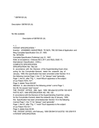
Apparatus for carrying out a process according to the invention and a
specific example of its use will now be described by way of example
with reference to the accompanying drawing in which, Fig. 1 is a
longitudinal cross-section of the apparatus and Fig. 2 a vertical
crosssection on the line Il11- of Fig. 1.
As shown in Fig. 1, the apparatus comprises an atomizer holder 1 to
which the hydrocarbon material is supplied at one end as indicated by
the arrow 7. The hydrocarbon is atomized 65 by a whirl chamber
atomizer situated at the other end of the holder 1 and injected into
the combustion chamber 2 so as to form a hollow conical jet. Although
an atomizer operated by means of the fuel pressure alone is preferred,
70 since in this way a fine atomization can be obtained in a simple
manner, it is also possible to use an atomizer requiring a stream of
an auxiliary atomizing fluid such as air or steam, provided a hollow
conical jet is obtained. The 75 atomizer holder 1 is mounted in the
oxygen chamber 3 which is mainly cylindrical. The combustion chamber
2, also mainly cylindrical has walls of refractory material and
communicates with the oxygen chamber 3 through an 80 opening 5 which
has a diameter smaller than the diameter of the chambers 2 and 3. The
diameter of the oxygen chamber 3 should be 12-2 times as great as that
of the opening 5.
The combustion chamber 2 is provided with an 85 annular ridge 4 to
which the shape of the oxygen chamber 3 is adapted.
The atomizer is arranged in the oxygen chamber 3 in a position such
that the hollow conical jet of atomized hydrocarbon passes near 90
FWti'd' 7 :
- 1 t 1 - 1 780,120 the edge of the opening 5 on entering the
combustion chamber 2. This position will depend on the apex angle of
the cone which is determined by the properties of the hydrocarbon, the
construction of the atomizer and the pressure with which the fuel is
applied to it.
The oxygen chamber 3 is provided at its periphery with a number of
tangential slots or nozzles 9 (see Fig. 2) which are placed at 1u
regular intervals around the circumference and through which
oxygen-containing gas from the case 10 can flow tangentially into the
oxygen chamber 3. During operation oxygen-containing gas is introduced
into the case -10 at a suitable super-atmospheric pressure. Owing to
the tangential component of flow on entering the oxygen chamber 3, the
oxygen-containing gas flows with a rotary motion about the axis of the
chamber 3 towards the opening 5, and as the diameter of the opening is
smaller than that of the oxygen chamber, the speed of rotation
4. increases considerably as the gas flows towards the opening 5.
The result is that the conical jet of fuel in passing close to the
edge of the opening 5 is forcibly entrained by the stream of
oxygencontaining gas also entering the combustion chamber 2 through
the opening 5, and a very intimate mixing of the hydrocarbon and
oxygen-containing gas occurs, which promotes both ignition and
combustion in the combustion chamber 2. The w211 of the combustion
chamber 2 which, when the apparatus is operating, is hot, imparts heat
to the hydrocarbon by radiation and thus promotes the evaporation,
vaporization, ignition and combustion thereof. Moreover, the shape of
the chamber 2 is such that, as shown in the drawving, toroidal
vortices are formed both inside and outside 4C the conical fuel jet
which, particularly in the case of the outermost vortex situated near
the ridge 4, return an already burning mixture to the place where the
ignition has to occur and thus promote the ignition of the hydrocarbon
entering the combustion chamber 2.
A tube 6 is also provided which surrounds the atomizer holder 1. A
combustible gas can be supplied to the tube 6 through the inlet 8 and
can enter the air chamber around the atomizer nozzle. It has been
found that in the apparatus a combustible gas can be burnt either at
the same time as a liquid hydrocarbon or separately. The gaseous fuel
can be used when there is a temporary shortage of the liquid
hydrocarbon.
The oxygen-containing gas supplied preferably consists either of
substantially pure oxygen or air to which, if desired, additional
oxygen -has been- added.
The amount of oxygen to be used will, of course, have to be smaller
than the quantity required for a complete combustion of the
hydrocarbon. When heavier hydrocarbons are used as initial material,
the oxygen-containing gas used may be mixed with steam, before_ being
passed into the reaction chamber.
Usually a mixture of approximately equal parts by weight of oxygen and
steam is supplied for the partial combustion of heavy products.
Preferably approximately 1.25 kg of oxygen 70 are used per kg of
hydrocarbon.
The reaction is carried out at a temperature of from 1200-1500 C., and
preferably from 1300-1400 C. The pressure used is at least 3
atmospheres, and is preferably higher than 75 atmospheres. The
pressure used depends on the pressure at which the gas mixture formed
is further processed. Thus the combustion reaction is carried out at
elevated pressure if the gas mixture formed is used, for 80 example,
for an ammonia synthesis, which is carried out at a very high
pressure. When the pressure is greater than 3 atmospheres, the
advantage obtained is that the small amount of soot which is present
5. in the resulting gas mixture may be very easily removed by scrubbing
with water. The partial combustion lasts for less than 4 seconds. Such
a short reaction time is very important for the prevention of
undesired side reactions. The gas mixture 90 formed is preferably
rapidly cooled. Such a short reaction time is possible with the use of
the apparatus described above since there is an intimate mixing in the
reaction chamber immediately after the introduction of the reaction
components, and also an immediate combustion of the reaction mixture
obtained.
The specific gravity and viscosity of the heavier hydrocarbons to
which the invention is particularly applicable may vary between 10
wide limits. Thus the specific gravity may lie between approximately
0.90 and 1.05; the viscosity may vary between that of a gas oil and
that of an asphalt with a penetration of 10-20 at 25 C., as determined
by the Institute 10 of Petroleum's Standard Method IP 49/56 for
measuring the penetration of bitumen, which is set out at p 371-4 of "
Standard Methods for testing Petroleum and its Products " (16th
Edition) published by the Institute of 11 Petroleum. Heavy products of
this type are preheated before being atomized. The mixture of
oxygen-containing gas and steam supplied is also preferably preheated
before being fed into the combustion chamber 2. 11 EXAMPLE
An apparatus of the design shown in Figs.
I and II, the combustion chamber of which was cm long and had a
diameter of 40 cm, was used for the partial combustion of a high 12
sulphur residual fuel oil with a viscosity of 3500 sec. Redwood I at
37.80 C. Preheated oxygen and super-heated steam, preheated to about
400 C., were passed into the combustion chamber under a pressure of 20
atmos- 12 pheres and at a temperature of about 13000 C.
For each 100 kg of oil supplied 85 cubic metres (measured at N.T.P.)
of oxygen and 90 kg of steam were supplied to give 310 cubic metres
4a1 pressure in the combustion chamber being at 35 least 3
atmospheres.
* Sitemap
* Accessibility
* Legal notice
* Terms of use
* Last updated: 08.04.2015
* Worldwide Database
* 5.8.23.4; 93p